EP3608649B1 - Stützmast eines turbotriebwerks eines luftfahrzeugs - Google Patents
Stützmast eines turbotriebwerks eines luftfahrzeugs Download PDFInfo
- Publication number
- EP3608649B1 EP3608649B1 EP19190151.1A EP19190151A EP3608649B1 EP 3608649 B1 EP3608649 B1 EP 3608649B1 EP 19190151 A EP19190151 A EP 19190151A EP 3608649 B1 EP3608649 B1 EP 3608649B1
- Authority
- EP
- European Patent Office
- Prior art keywords
- pylon
- plate
- turbomachine
- pipes
- longitudinal end
- Prior art date
- Legal status (The legal status is an assumption and is not a legal conclusion. Google has not performed a legal analysis and makes no representation as to the accuracy of the status listed.)
- Active
Links
Images



Classifications
-
- G—PHYSICS
- G01—MEASURING; TESTING
- G01M—TESTING STATIC OR DYNAMIC BALANCE OF MACHINES OR STRUCTURES; TESTING OF STRUCTURES OR APPARATUS, NOT OTHERWISE PROVIDED FOR
- G01M15/00—Testing of engines
- G01M15/14—Testing gas-turbine engines or jet-propulsion engines
-
- G—PHYSICS
- G01—MEASURING; TESTING
- G01M—TESTING STATIC OR DYNAMIC BALANCE OF MACHINES OR STRUCTURES; TESTING OF STRUCTURES OR APPARATUS, NOT OTHERWISE PROVIDED FOR
- G01M15/00—Testing of engines
- G01M15/02—Details or accessories of testing apparatus
-
- B—PERFORMING OPERATIONS; TRANSPORTING
- B64—AIRCRAFT; AVIATION; COSMONAUTICS
- B64F—GROUND OR AIRCRAFT-CARRIER-DECK INSTALLATIONS SPECIALLY ADAPTED FOR USE IN CONNECTION WITH AIRCRAFT; DESIGNING, MANUFACTURING, ASSEMBLING, CLEANING, MAINTAINING OR REPAIRING AIRCRAFT, NOT OTHERWISE PROVIDED FOR; HANDLING, TRANSPORTING, TESTING OR INSPECTING AIRCRAFT COMPONENTS, NOT OTHERWISE PROVIDED FOR
- B64F5/00—Designing, manufacturing, assembling, cleaning, maintaining or repairing aircraft, not otherwise provided for; Handling, transporting, testing or inspecting aircraft components, not otherwise provided for
- B64F5/60—Testing or inspecting aircraft components or systems
-
- F—MECHANICAL ENGINEERING; LIGHTING; HEATING; WEAPONS; BLASTING
- F01—MACHINES OR ENGINES IN GENERAL; ENGINE PLANTS IN GENERAL; STEAM ENGINES
- F01D—NON-POSITIVE DISPLACEMENT MACHINES OR ENGINES, e.g. STEAM TURBINES
- F01D25/00—Component parts, details, or accessories, not provided for in, or of interest apart from, other groups
- F01D25/28—Supporting or mounting arrangements, e.g. for turbine casing
- F01D25/285—Temporary support structures, e.g. for testing, assembling, installing, repairing; Assembly methods using such structures
Definitions
- the present invention relates to a support pylon for an aircraft turbomachine, in particular for a test bench. It relates more particularly to the connection of fluid lines (s) from this pylon to the turbomachine.
- Turbomachinery requires, for their development or for the verification of their performance at the end of maintenance, and in order to be tested before being put into flight, a passage on ground installations, called test benches.
- test benches make it possible to operate the turbomachines as if they were installed on an aircraft.
- These benches are generally masonry installations in which is installed a fixed pylon comprising at least one fluid pipe such as gas configured to be able to be connected to a pipe of the turbomachine to be tested.
- the documents FR 3 044 093 A1 , CN 207 487 978 U and US 8 161 806 B1 show examples of test benches for testing an aircraft turbomachine.
- the fluid pipes of the pylon are rigid at least in a portion for connection to the pipe of the turbomachine. In this way, when docking the turbomachine which is heavy and difficult to handle, there is a risk of damaging the turbomachine in its portion of connection to the pylon.
- the invention proposes a simple, efficient and economical solution to this problem.
- the invention relates to a support pylon for an aircraft turbomachine, in particular for a test bench, the pylon having a general shape elongated along an axis and comprising, at a first longitudinal end , first members for fixing to a turbomachine and, at a second longitudinal end, second members for fixing to a base, the pylon being crossed by at least one fluid pipe comprising a first end of connection to the turbomachine and a second connection end to a fluid supply circuit, characterized in that said at least one pipe comprises a portion movable in translation along said axis so as to be able to adjust the position along said axis of said first connection end with respect to said first longitudinal end.
- the mobile portion and therefore the rigid part of the pipe is moved in translation along said axis. It is then possible to vary the position of the first end of connection of the pipe to the turbomachine between a first position, for example called the high position, and a second position, for example called the low position. In the high position, the first end of connection of the pipe to the turbomachine is in a position allowing its connection to a similar pipe of the turbomachine. In other words, said first connection end is located at a first predetermined distance from said first longitudinal end.
- the first connection end of the pipe to the turbomachine is set back, at a predetermined distance, relative to the first longitudinal end of the pylon.
- said first connection end is located at a second predetermined distance from said first longitudinal end, said first predetermined distance being greater than said second predetermined distance.
- said at least one pipe comprises a flexible portion situated, for example, at the level of the second end of connection to the base.
- said movable portion passes through an orifice of a plate substantially perpendicular to said axis and carries two fixed rings, a first of which is located on one side of the plate and forms a stop and a second of which is located on the other side of the plate. plate, a compression spring bearing on the second ring and on the plate to urge the removal of the second ring from the plate.
- the solution makes it possible to keep the pipes in a high position and allows freedom of intrinsic movements of the pipe due for example to thermal expansion or to vibrations.
- the plate is connected to a pylon body by guide means in translation along said axis.
- the translational guide means comprise two telescopic rods, the ends of which are respectively fixed to the plate and to the body of the pylon.
- the translational guide means comprise at least one endless screw.
- the plate is connected to or comprises at least one handle for moving the plate and therefore for adjusting the position of the movable portion.
- the pylon comprises several fluid conduits and the plate comprises several orifices crossed by said conduits.
- the pylon comprises means for locking said movable portion in at least one position along said axis.
- This method makes it possible to dock an aircraft turbomachine on a pylon without risk of deterioration of said turbomachine in its portion of connection to said pylon.
- the terms “lower”, “upper,“ proximal ”,“ distal ”,“ top ”and“ bottom ” are used with reference to the usual positioning of the constituent elements of the pylon according to the invention, the terms“ proximal ” ",” Lower “and” bottom “being understood as being closest to the base while the terms” distal ",” upper “and” top “being understood as being closest to the turbomachine docked to the pylon according to the invention.
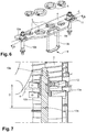
- the figures 1 and 2 illustrate a pylon 1 for supporting an aircraft turbomachine T according to the invention.
- This pylon in particular for a test bench, is surmounted by a turbomachine T and has a general shape elongated along an axis AA.
- the pylon comprises first members for fixing to a turbomachine T, the turbomachine T comprising, in a zone for connection to the pylon 1, complementary members for fixing to the pylon.
- the pylon comprises second members for fixing to a base E itself fixed to the ground or to a wall of a masonry installation comprising the pylon 1.
- the base E comprises, in a zone of connection to the pylon 1, complementary members for fixing to the pylon.
- the turbomachine T has a longitudinal axis BB substantially perpendicular to the axis AA when the turbomachine T is docked on the pylon 1.
- the axis AA of the pylon forms an angle ⁇ with respect to a horizontal plane passing through a radial plane of the turbomachine. T, for example an angle ⁇ of between 30 ° and 40 °, reproducing the inclination of an aircraft pylon.
- the pylon 1 is for example tubular and is crossed, longitudinally, by at least one pipe 2 and, as illustrated in the present application, by several pipes 2 of fluids and cables necessary for carrying out tests of the turbomachine on a test bench.
- the pylon 1 comprises at least one fluid pipe 2 comprising a first end 2a for connection to the turbomachine T and a second end 2b for connection to a circuit C for supplying fluid.
- the pylon 1 comprises at least four fluid pipes 2, for example making it possible to circulate fluids, such as gas, between the base E and the turbomachine T.
- the or each fluid pipe 2 of the pylon 1 comprises a portion 2 'movable in translation along the axis AA so as to be able to adjust the position of the first connection end 2a with respect to the first longitudinal end 1a of the pylon 1, along the AA axis.
- the portion 2 'movable in translation is formed by a rigid portion of the pipes 2.
- This arrangement allows the withdrawal of the pipe (s) 2 at the level of the distal end 1a of the pylon 1, in other words it allows the removal or temporary separation of the first connection end 2a of each pipe 2 from the first longitudinal end 1a pylon 1, for example during the phase of docking of the turbine engine T to pylon 1.
- the flexible portion 2c allowing the adjustment of the position of the movable portion 2 'of each pipe 2 is located at the level of the second end 2b of connection to the 'base E.
- This flexible portion could be fitted anywhere, along each pipe 2.
- each pipe 2 passes through an orifice 3 of a plate 4, the latter extending substantially perpendicularly to the axis AA of the pylon 1.
- each pipe 2 carries two fixed rings 5, 6.
- a first ring 5 is located on a lower side of the plate 4 and forms a stop and a second 6 is located on the other side of the plate. 4
- a compression spring 7 bearing on the second ring 6 and on the plate 4 to urge the separation of the second ring 6 from the plate 4.
- the compression spring 7 bears on the plate 4 by the 'intermediary of a third ring 8 located on an upper side of the plate 4.
- the plate 4 comprises several orifices 3 through which the conduits 2 pass, in this way, it is possible to move, simultaneously, all of the conduits 2 in order to adjust the position of their respective first end 2a of connection thus simplifying the docking operations of a turbomachine T, on a pylon, and, consequently, the maintenance or test operations on the turbomachine T.
- the plate 4 is connected to a pylon body 1c by guide means in translation along the axis A-A.
- the translation guide means comprise two telescopic rods 10 whose ends are respectively fixed to the plate 4 and to the body of the pylon 1. More precisely, the telescopic rods 10 comprise, on the one hand, a hollow cylinder 10a integral with the plate 4, for example by means of fixing lugs 11 screwed into the plate 4 and, on the other hand, a cylindrical rod 10b, integral with the pylon 1 and configured to slide in the hollow cylinder 10a.
- both rods telescopic 10 are arranged on a straight line d located along a longitudinal axis of the plate 4 and at two opposite ends of this plate.
- the adjustment of the position of the movable portion 2 'of the pipe or pipes 2 is carried out between a high position allowing the connection of the pipes 2 of the pylon 1 to similar pipes of the turbomachine T and a low position in which the portions movable pipes 2 'of the pipes 2 are set back relative to the first longitudinal end 1a of the pylon 1.
- the pylon 1 also comprises means for locking the position of the movable portion 2 ′ of the pipe or pipes 2, in at least one position, for example high position or low position.
- the locking means are constituted by pins 12 which can be engaged in high 13a and low 13b notches formed in the telescopic rods 10 constituting the guide means, and in particular in the cylindrical rods 10b of these. last.
- These pins 12 are retractable and pass through an orifice formed in a peripheral wall of the hollow cylinder 10a. The pins 12 then lock the positioning of the movable portions 2 'of the pipes 2 in the high position or the low position by engaging respectively in the upper notches 13a or the lower notches 13b of the cylindrical rods 10b.
- the high and low positions are spaced apart by a distance D sufficient to allow the removal of the movable portions 2 ', and, consequently, of the first ends 2a for connecting the pipes 2 to the turbomachine T so as to ensure the secure docking without risk of damage to the latter.
- the high and low positions, and therefore the high 13a and low 13b notches are spaced 100 mm apart.
- the translational guide means comprise at least one endless screw, in this way it is possible to select a plurality of positions for erasing the movable portions 2 ′ of the pipes 2.
- the plate 4 is connected to or comprises at least one handle 9 allowing the movement of the plate 4 and therefore adjusting the position of the movable portion 2 'of the pipe or pipes 2.
- This handle 9 has a general O-shaped shape and comprises one or two gripping zones which can be entered by an operator in order to adjust the position of the mobile portion 2 'of the pipes 2.
- the handle 9 extends in a plane perpendicular to the plate 4 and is cut by the plate 4 so as to define two gripping zones, namely an upper gripping zone 9a and a lower gripping zone 9b.
- two access doors 14 to the translational guide means are provided in the body of the pylon 1 and in particular allow the grip 9 to be gripped in order to move the assembly formed by the plate 4 and the movable portions 2 'of the pipes 2 between a high position and a low position.
- the present invention also relates to a method for mounting an aircraft turbomachine T on a pylon 1 as described in the present description and comprising at least one fluid pipe 2.
- the pipes 2 are locked in a high position in which the pins 12 are engaged in the upper notches 13a of the telescopic rods 10.
- a first step a) the position of the movable portion 2 'of the at least one pipe 2 is moved in the direction of the second longitudinal end 1b of the pylon 1 so that the first end 2a for connecting the pipes 2 is located at a first predetermined distance D 1 from the first longitudinal end 1a of the pylon 1 ( figure 5a ).
- the pins 12 are released from the top notches 13a and, for example by maneuvering on the lower zone 9b of the handle 9 through one of the hatches 14, the assembly consisting of the plate 4 and the pipes. 2 is moved downwards, until the pins 12 are brought opposite the lower notches 13b.
- a second step b) the turbomachine T is docked in a manner known per se on the first longitudinal end 1a for connecting the pylon 1 to the turbomachine.
- a third step c) the movable portion 2 'of the pipes 2 is moved towards the first longitudinal end 1a of the pylon 1 so that the first end 2a for connecting the pipes 2 is located at a second predetermined distance D 2 from the first longitudinal end 1a of the pylon 1 ( Figure 5b ).
- the first predetermined distance D 1 is greater than the second predetermined distance D 2
- the pins 12 are released from the lower notches 13b and, for example by maneuvering on the upper zone 9a of the handle 9, the assembly consisting of the plate 4 and pipes 2 is moved upwards, until the pins 12 are brought opposite the upper notches 13a.
- the pins 12 are then engaged in these high notches 13a so as to lock the assembly consisting of the plate 4 and the pipes 2 in the high starting position.
- the rings 5 and 6 are fixed on the pipes 2 and the compression springs 7 bear, on the one hand, against the ring 6 and, on the other hand, against the plate 4, directly or via the rings 8
- the compression springs 7 are compressed between the rings 6 and the plate 4 (or the rings 8 where appropriate).
- the distance separating the rings 6 from the plate 4 (or rings 8, if applicable) when the pipes 2 are in the high position is less than the distance separating the rings 6 from the plate 4 (or rings 8, if applicable) when the pipes 2 are in the low position.
- the compression springs 7 then exert a force tending to move the rings 6 away from the plate 4 (or rings 8, if applicable).
- the compression springs 7 thus make it possible to maintain the pipes 2 in the high position by resting on the plate 4, directly or via the rings 8. Otherwise, the pipes 2 would slide in the orifices 3 downwards, in particular during the disconnection of the connections between the pipes 2 of the pylon 1 from those of the turbomachine T, generating harmful forces on the connections of the pipes 2 of the pylon 1 and of the turbomachine T.
- a clearance j is provided between the ring 5 and the plate 4 when the pipes 2 are in the high position.
- This clearance j allows the displacements of the pipes 2 induced for example by their expansion, along the axis A-A.
- the plate 4 being fixed to the pylon body 1c by means of the telescopic rods 10, it is necessary to take into account the axial displacements of the pipes 2.
- This clearance j is between 5 mm and 10 mm and is preferably of the order of 8 mm.
- the mobile portions 2 'and, consequently, the first ends 2a for connecting the pipes 2 are moved upwards and brought closer to the first longitudinal end 1a for connecting the pylon 1 to the turbomachine T.
- each pipe 2 is connected, via its first connection end 2a, to a similar pipe of the turbomachine T.
- the turbomachine T is fixed to the pylon 1 before or after step c).
Landscapes
- Engineering & Computer Science (AREA)
- Physics & Mathematics (AREA)
- General Physics & Mathematics (AREA)
- Chemical & Material Sciences (AREA)
- Combustion & Propulsion (AREA)
- Manufacturing & Machinery (AREA)
- Transportation (AREA)
- Aviation & Aerospace Engineering (AREA)
- Supports For Pipes And Cables (AREA)
- Wind Motors (AREA)
Claims (10)
- Stützmast (1) einer Turbomaschine (T) eines Luftfahrzeugs, insbesondere für einen Prüfstand, wobei der Mast eine allgemeine entlang einer Achse (A-A) gestreckte Form aufweist und an einem ersten Längsende (1a) erste Organe zum Befestigen an einer Turbomaschine umfasst, und an einem zweiten Längsende (1b) zweite Organe zum Befestigen an einem Sockel (E), wobei der Mast von mindestens einer Fluidleitung (2) durchquert ist, die ein erstes Ende (2a) zum Anschließen an die Turbomaschine (T) und ein zweites Ende (2b) zum Anschließen an einem Fluidversorgungskreislauf (C) umfasst, dadurch gekennzeichnet, dass die mindestens eine Leitung (2) einen Abschnitt (2') umfasst, der in Verschiebung entlang der Achse (A-A) derart beweglich ist, dass er die Position entlang der Achse (A-A) des ersten Endes (2a) zum Anschließen in Bezug auf das erste Längsende (1a) einstellen kann.
- Mast (1) nach dem vorstehenden Anspruch, dadurch gekennzeichnet, dass mindestens eine Leitung (2) einen biegsamen Abschnitt (2c) umfasst, der zum Beispiel in dem Bereich des zweiten Endes (2b) zum Anschließen an dem Sockel (E) liegt.
- Mast (1) nach einem der vorstehenden Ansprüche, wobei der bewegliche Abschnitt (2') eine Öffnung (3) einer Platte (4) durchquert, die im Wesentlichen zu der Achse (A-A) senkrecht ist und zwei stationäre Ringe (5, 6) trägt, von welchen der erste (5) auf einer Seite der Platte (4) liegt und einen Anschlag bildet, und von welchen der zweite (6) auf der anderen Seite der Platte liegt, wobei eine Druckfeder (7) auf dem zweiten Ring (6) und auf der Platte (4) anliegt, um das Beabstanden des zweiten Rings (6) der Platte (4) vorzuspannen.
- Mast (1) nach dem vorstehenden Anspruch, wobei die Platte (4) mit einem Mastkörper (1c) durch Verschiebungsführungsmittel entlang der Achse (A-A) verbunden ist.
- Mast (1) nach dem vorstehenden Anspruch, wobei die Verschiebungsführungsmittel zwei teleskopische Schäfte (10) umfassen, deren Enden jeweils an der Platte (4) und an dem Körper (1c) des Mastes befestigt sind.
- Mast nach Anspruch 4, wobei die Verschiebungsführungsmittel mindestens eine Endlosschraube umfassen.
- Mast (1) nach einem der Ansprüche 3 bis 6, wobei die Platte (4) mit mindestens einem Griff (9) zum Verlagern der Platte und daher Einstellen der Position des beweglichen Abschnitts (2') verbunden ist oder einen umfasst.
- Mast (1) nach einem der Ansprüche 3 bis 7, wobei der Mast mehrere Fluidleitungen (2) umfasst, und die Platte (4) mehrere Öffnungen (3), die von den Leitungen (2) durchquert werden, umfasst.
- Mast (1) nach einem der vorstehenden Ansprüche, der Verriegelungsmittel des beweglichen Abschnitts (2') in mindestens einer Position entlang der Achse (A-A) umfasst.
- Montageverfahren einer Turbomaschine (T) eines Luftfahrzeugs auf einem Mast (1) nach einem der Ansprüche 1 bis 9, das umfasst:a) einen Verlagerungsschritt des beweglichen Abschnitts (2') der Leitungen (2) in Richtung des zweiten Längsendes (1b) des Mastes (1) derart, dass das erste Ende (2a) zum Anschließen in einem ersten vorbestimmten Abstand (D1) von dem ersten Längsende (1a) des Mastes (1) liegt,b) einen Andockschritt der Turbomaschine auf dem ersten Längsende (1a),c) einen Verlagerungsschritt des beweglichen Abschnitts (2') der Leitungen (2) in Richtung des ersten Längsendes (1a) des Mastes (1) derart, dass das erste Ende (2a) zum Anschließen in einem zweiten vorbestimmten Abstand (D2) von dem ersten Längsende (1a) liegt, wobei der erste vorbestimmte Abstand (D1) größer ist als der zweite vorbestimmte Abstand (D2), undd) einen Anschlussschritt der mindestens einen Leitung an der Turbomaschine,wobei die Turbomaschine an dem Mast vor dem Schritt c) oder nach dem Schritt c) oder d) befestigt wird.
Applications Claiming Priority (1)
| Application Number | Priority Date | Filing Date | Title |
|---|---|---|---|
| FR1857409A FR3084931B1 (fr) | 2018-08-09 | 2018-08-09 | Pylone de support d'une turbomachine d'aeronef |
Publications (2)
| Publication Number | Publication Date |
|---|---|
| EP3608649A1 EP3608649A1 (de) | 2020-02-12 |
| EP3608649B1 true EP3608649B1 (de) | 2021-02-17 |
Family
ID=65201058
Family Applications (1)
| Application Number | Title | Priority Date | Filing Date |
|---|---|---|---|
| EP19190151.1A Active EP3608649B1 (de) | 2018-08-09 | 2019-08-06 | Stützmast eines turbotriebwerks eines luftfahrzeugs |
Country Status (4)
| Country | Link |
|---|---|
| US (1) | US11435263B2 (de) |
| EP (1) | EP3608649B1 (de) |
| CN (1) | CN110823582B (de) |
| FR (1) | FR3084931B1 (de) |
Families Citing this family (1)
| Publication number | Priority date | Publication date | Assignee | Title |
|---|---|---|---|---|
| CN115436065B (zh) * | 2022-11-08 | 2023-03-24 | 中国航发四川燃气涡轮研究院 | 一种用于航空发动机试车台的多功能台架 |
Family Cites Families (14)
| Publication number | Priority date | Publication date | Assignee | Title |
|---|---|---|---|---|
| US2481502A (en) * | 1943-07-27 | 1949-09-13 | George G Downing | Mechanism for projecting and retracting aircraft lift rotors |
| US20090167023A1 (en) * | 2007-12-27 | 2009-07-02 | Jacob Johannes Nies | Forward leaning tower top section |
| FR2944871B1 (fr) * | 2009-04-22 | 2011-07-01 | Snecma | Tete d'etancheite pour une installation de tests fluidiques sur une piece de turbomachine d'aeronef |
| FR2948153B1 (fr) * | 2009-07-15 | 2011-12-30 | Saipem Sa | Eolienne maritime a pylone ajuste verticalement par calage |
| ITMI20100247U1 (it) * | 2010-07-16 | 2012-01-17 | Fimac S P A | Dispositivo per l'azionamento a terra di turbine aerodinamiche di azionamento di circuiti di servizio di aerei, particolarmente di circuiti di raffreddamento di dispositivi elettronici. |
| US8161806B1 (en) * | 2010-12-23 | 2012-04-24 | General Electric Company | Method of monitoring engine performance parameters of a gas turbine engine |
| RU2540202C2 (ru) * | 2012-09-04 | 2015-02-10 | Федеральное государственное унитарное предприятие "Центральный институт авиационного моторостроения им. П.И. Баранова" | Стенд для испытания авиационных двигателей |
| CN103353399B (zh) * | 2013-07-03 | 2015-08-26 | 山河智能装备股份有限公司 | 活塞发动机力学性能测试试验台 |
| EP3049657B1 (de) * | 2013-09-27 | 2018-10-03 | United Technologies Corporation | Montagesysteme für gasturbinenmotoren |
| DE202014106021U1 (de) * | 2014-12-12 | 2015-01-29 | Fft Produktionssysteme Gmbh & Co. Kg | Testanordnung für Rückstau- oder Staudruckturbine |
| FR3044093B1 (fr) * | 2015-11-19 | 2017-12-15 | Snecma | Banc d'essai pour turboreacteur |
| BE1024535B1 (fr) * | 2016-09-05 | 2018-04-04 | Safran Aero Boosters S.A. | Banc d'essai de turbomachine avec contrôle actif du bruit |
| US10871402B2 (en) * | 2017-03-31 | 2020-12-22 | Safran Aircraft Engines | Device for measuring the characteristics of an air flow |
| CN207487978U (zh) * | 2017-10-30 | 2018-06-12 | 中科航星科技有限公司 | 涡喷发动机地面试车检测台及其检测系统 |
-
2018
- 2018-08-09 FR FR1857409A patent/FR3084931B1/fr not_active Expired - Fee Related
-
2019
- 2019-08-06 EP EP19190151.1A patent/EP3608649B1/de active Active
- 2019-08-07 US US16/534,864 patent/US11435263B2/en active Active
- 2019-08-08 CN CN201910730364.8A patent/CN110823582B/zh active Active
Non-Patent Citations (1)
| Title |
|---|
| None * |
Also Published As
| Publication number | Publication date |
|---|---|
| EP3608649A1 (de) | 2020-02-12 |
| CN110823582A (zh) | 2020-02-21 |
| CN110823582B (zh) | 2023-09-05 |
| FR3084931A1 (fr) | 2020-02-14 |
| FR3084931B1 (fr) | 2020-08-07 |
| US11435263B2 (en) | 2022-09-06 |
| US20200049591A1 (en) | 2020-02-13 |
Similar Documents
| Publication | Publication Date | Title |
|---|---|---|
| EP3692247B1 (de) | Vorrichtung zum zusammenbau eines turbinentriebwerks und verfahren unter verwendung der vorrichtung | |
| EP1957843A1 (de) | Anordnung von stützbojen für eine flexible unterwasser-rohrleitung | |
| EP3841645A1 (de) | Anordnung zum schutz und zur sicherung eines kabelbaumes | |
| EP3084140B1 (de) | Führungsarm für gegenstände mit länglicher form, insbesondere für eine turbomaschine | |
| EP2393713B1 (de) | Triebwerksverkleidung | |
| WO2016193641A1 (fr) | Dispositif de verrouillage de capots pivotants d'un inverseur de poussée | |
| FR2661451A1 (fr) | Puits sous-marin. | |
| EP3608649A1 (de) | Stützmast eines turbotriebwerks eines luftfahrzeugs | |
| FR2953901A1 (fr) | Dispositif de maintien d'un embout de connexion d'une conduite flexible dans une installation de pose en mer. | |
| EP2108586A1 (de) | Teleskopmast für den Weltraum mit Verriegelung unter Restspanndruck | |
| WO2017077219A1 (fr) | Tube de degazage et cone d'ejection pour une turbomachine, ainsi que leur outillage de montage | |
| EP1727961B1 (de) | Verfahren und system zur inbetriebnahme einer rohrleitung | |
| EP4311782A1 (de) | System zur handhabung einer seitenschale eines flugzeugs zur montage eines rumpfkörpers eines flugzeugs und verfahren zur montage eines rumpfkörpers eines flugzeugs | |
| FR3051854A1 (fr) | Carter d'echappement de turbomachine | |
| WO2014114890A1 (fr) | Ensemble de connexion sous-marin et methode de connexion | |
| FR2979316A1 (fr) | Module prefabrique d'habillage interieur d'au moins une partie d'un habitacle, ensemble forme d'un habitacle et du module precite, et procede d'installation d'un tel module dans un habitacle | |
| EP2322421B1 (de) | Träger zum unterstützen, lagern und/oder stabilisieren eines Aggregats oder einer Structur und Verfahren zum anpassen und blockieren eines solchen Trägers bei besagter Länge | |
| FR2897402A1 (fr) | Dispositif de separation d'objets a l'aide d'un gaz | |
| FR3018336A1 (fr) | Dispositif de connexion d'une conduite amovible et canalisation pourvue d'un tel dispositif | |
| FR3101616A1 (fr) | Procédé et dispositif pour l'installation d'une ferrure de positionnement d'un capot de soufflante. | |
| EP0285512B1 (de) | Trägereinrichtung für zwei Steckverbinderelemente, die jeweils mit zwei lösbar zusammenstellbaren Sitzflächen verbunden sind und einen gegenseitigen Positionierungsabstand aufweisen und eine solche Trägereinrichtung verwendende Verbindungseinrichtung | |
| FR2694537A1 (fr) | Dispositif d'accrochage d'une turbomachine sur une structure d'aéronef. | |
| EP3850195A1 (de) | Abnehmbare trägerschnittstelle für eine ringförmige turbomaschine | |
| FR2960927A1 (fr) | Attache volante de support et de fixation d'une structure sur une paroi, munie d'un adaptateur | |
| EP4544210B1 (de) | Vorrichtung zur schwingungsdämpfenden führung von rohrleitungen |
Legal Events
| Date | Code | Title | Description |
|---|---|---|---|
| PUAI | Public reference made under article 153(3) epc to a published international application that has entered the european phase |
Free format text: ORIGINAL CODE: 0009012 |
|
| STAA | Information on the status of an ep patent application or granted ep patent |
Free format text: STATUS: REQUEST FOR EXAMINATION WAS MADE |
|
| 17P | Request for examination filed |
Effective date: 20190806 |
|
| AK | Designated contracting states |
Kind code of ref document: A1 Designated state(s): AL AT BE BG CH CY CZ DE DK EE ES FI FR GB GR HR HU IE IS IT LI LT LU LV MC MK MT NL NO PL PT RO RS SE SI SK SM TR |
|
| AX | Request for extension of the european patent |
Extension state: BA ME |
|
| GRAP | Despatch of communication of intention to grant a patent |
Free format text: ORIGINAL CODE: EPIDOSNIGR1 |
|
| STAA | Information on the status of an ep patent application or granted ep patent |
Free format text: STATUS: GRANT OF PATENT IS INTENDED |
|
| RIC1 | Information provided on ipc code assigned before grant |
Ipc: G01M 15/02 20060101AFI20200914BHEP Ipc: B64F 5/60 20170101ALI20200914BHEP Ipc: G01M 15/14 20060101ALI20200914BHEP Ipc: F01D 25/28 20060101ALI20200914BHEP |
|
| INTG | Intention to grant announced |
Effective date: 20201001 |
|
| GRAS | Grant fee paid |
Free format text: ORIGINAL CODE: EPIDOSNIGR3 |
|
| GRAA | (expected) grant |
Free format text: ORIGINAL CODE: 0009210 |
|
| STAA | Information on the status of an ep patent application or granted ep patent |
Free format text: STATUS: THE PATENT HAS BEEN GRANTED |
|
| AK | Designated contracting states |
Kind code of ref document: B1 Designated state(s): AL AT BE BG CH CY CZ DE DK EE ES FI FR GB GR HR HU IE IS IT LI LT LU LV MC MK MT NL NO PL PT RO RS SE SI SK SM TR |
|
| REG | Reference to a national code |
Ref country code: GB Ref legal event code: FG4D Free format text: NOT ENGLISH |
|
| REG | Reference to a national code |
Ref country code: CH Ref legal event code: EP |
|
| REG | Reference to a national code |
Ref country code: DE Ref legal event code: R096 Ref document number: 602019002577 Country of ref document: DE |
|
| REG | Reference to a national code |
Ref country code: AT Ref legal event code: REF Ref document number: 1362064 Country of ref document: AT Kind code of ref document: T Effective date: 20210315 |
|
| REG | Reference to a national code |
Ref country code: IE Ref legal event code: FG4D Free format text: LANGUAGE OF EP DOCUMENT: FRENCH |
|
| REG | Reference to a national code |
Ref country code: SE Ref legal event code: TRGR |
|
| REG | Reference to a national code |
Ref country code: LT Ref legal event code: MG9D |
|
| REG | Reference to a national code |
Ref country code: NL Ref legal event code: MP Effective date: 20210217 |
|
| PG25 | Lapsed in a contracting state [announced via postgrant information from national office to epo] |
Ref country code: GR Free format text: LAPSE BECAUSE OF FAILURE TO SUBMIT A TRANSLATION OF THE DESCRIPTION OR TO PAY THE FEE WITHIN THE PRESCRIBED TIME-LIMIT Effective date: 20210518 Ref country code: FI Free format text: LAPSE BECAUSE OF FAILURE TO SUBMIT A TRANSLATION OF THE DESCRIPTION OR TO PAY THE FEE WITHIN THE PRESCRIBED TIME-LIMIT Effective date: 20210217 Ref country code: BG Free format text: LAPSE BECAUSE OF FAILURE TO SUBMIT A TRANSLATION OF THE DESCRIPTION OR TO PAY THE FEE WITHIN THE PRESCRIBED TIME-LIMIT Effective date: 20210517 Ref country code: HR Free format text: LAPSE BECAUSE OF FAILURE TO SUBMIT A TRANSLATION OF THE DESCRIPTION OR TO PAY THE FEE WITHIN THE PRESCRIBED TIME-LIMIT Effective date: 20210217 Ref country code: LT Free format text: LAPSE BECAUSE OF FAILURE TO SUBMIT A TRANSLATION OF THE DESCRIPTION OR TO PAY THE FEE WITHIN THE PRESCRIBED TIME-LIMIT Effective date: 20210217 Ref country code: PT Free format text: LAPSE BECAUSE OF FAILURE TO SUBMIT A TRANSLATION OF THE DESCRIPTION OR TO PAY THE FEE WITHIN THE PRESCRIBED TIME-LIMIT Effective date: 20210617 Ref country code: NO Free format text: LAPSE BECAUSE OF FAILURE TO SUBMIT A TRANSLATION OF THE DESCRIPTION OR TO PAY THE FEE WITHIN THE PRESCRIBED TIME-LIMIT Effective date: 20210517 |
|
| REG | Reference to a national code |
Ref country code: AT Ref legal event code: MK05 Ref document number: 1362064 Country of ref document: AT Kind code of ref document: T Effective date: 20210217 |
|
| PG25 | Lapsed in a contracting state [announced via postgrant information from national office to epo] |
Ref country code: RS Free format text: LAPSE BECAUSE OF FAILURE TO SUBMIT A TRANSLATION OF THE DESCRIPTION OR TO PAY THE FEE WITHIN THE PRESCRIBED TIME-LIMIT Effective date: 20210217 Ref country code: NL Free format text: LAPSE BECAUSE OF FAILURE TO SUBMIT A TRANSLATION OF THE DESCRIPTION OR TO PAY THE FEE WITHIN THE PRESCRIBED TIME-LIMIT Effective date: 20210217 Ref country code: LV Free format text: LAPSE BECAUSE OF FAILURE TO SUBMIT A TRANSLATION OF THE DESCRIPTION OR TO PAY THE FEE WITHIN THE PRESCRIBED TIME-LIMIT Effective date: 20210217 Ref country code: PL Free format text: LAPSE BECAUSE OF FAILURE TO SUBMIT A TRANSLATION OF THE DESCRIPTION OR TO PAY THE FEE WITHIN THE PRESCRIBED TIME-LIMIT Effective date: 20210217 |
|
| PG25 | Lapsed in a contracting state [announced via postgrant information from national office to epo] |
Ref country code: IS Free format text: LAPSE BECAUSE OF FAILURE TO SUBMIT A TRANSLATION OF THE DESCRIPTION OR TO PAY THE FEE WITHIN THE PRESCRIBED TIME-LIMIT Effective date: 20210617 |
|
| PG25 | Lapsed in a contracting state [announced via postgrant information from national office to epo] |
Ref country code: SM Free format text: LAPSE BECAUSE OF FAILURE TO SUBMIT A TRANSLATION OF THE DESCRIPTION OR TO PAY THE FEE WITHIN THE PRESCRIBED TIME-LIMIT Effective date: 20210217 Ref country code: AT Free format text: LAPSE BECAUSE OF FAILURE TO SUBMIT A TRANSLATION OF THE DESCRIPTION OR TO PAY THE FEE WITHIN THE PRESCRIBED TIME-LIMIT Effective date: 20210217 Ref country code: CZ Free format text: LAPSE BECAUSE OF FAILURE TO SUBMIT A TRANSLATION OF THE DESCRIPTION OR TO PAY THE FEE WITHIN THE PRESCRIBED TIME-LIMIT Effective date: 20210217 Ref country code: EE Free format text: LAPSE BECAUSE OF FAILURE TO SUBMIT A TRANSLATION OF THE DESCRIPTION OR TO PAY THE FEE WITHIN THE PRESCRIBED TIME-LIMIT Effective date: 20210217 |
|
| REG | Reference to a national code |
Ref country code: DE Ref legal event code: R097 Ref document number: 602019002577 Country of ref document: DE |
|
| PG25 | Lapsed in a contracting state [announced via postgrant information from national office to epo] |
Ref country code: DK Free format text: LAPSE BECAUSE OF FAILURE TO SUBMIT A TRANSLATION OF THE DESCRIPTION OR TO PAY THE FEE WITHIN THE PRESCRIBED TIME-LIMIT Effective date: 20210217 Ref country code: SK Free format text: LAPSE BECAUSE OF FAILURE TO SUBMIT A TRANSLATION OF THE DESCRIPTION OR TO PAY THE FEE WITHIN THE PRESCRIBED TIME-LIMIT Effective date: 20210217 Ref country code: RO Free format text: LAPSE BECAUSE OF FAILURE TO SUBMIT A TRANSLATION OF THE DESCRIPTION OR TO PAY THE FEE WITHIN THE PRESCRIBED TIME-LIMIT Effective date: 20210217 |
|
| PLBE | No opposition filed within time limit |
Free format text: ORIGINAL CODE: 0009261 |
|
| STAA | Information on the status of an ep patent application or granted ep patent |
Free format text: STATUS: NO OPPOSITION FILED WITHIN TIME LIMIT |
|
| 26N | No opposition filed |
Effective date: 20211118 |
|
| PG25 | Lapsed in a contracting state [announced via postgrant information from national office to epo] |
Ref country code: ES Free format text: LAPSE BECAUSE OF FAILURE TO SUBMIT A TRANSLATION OF THE DESCRIPTION OR TO PAY THE FEE WITHIN THE PRESCRIBED TIME-LIMIT Effective date: 20210217 Ref country code: AL Free format text: LAPSE BECAUSE OF FAILURE TO SUBMIT A TRANSLATION OF THE DESCRIPTION OR TO PAY THE FEE WITHIN THE PRESCRIBED TIME-LIMIT Effective date: 20210217 |
|
| PG25 | Lapsed in a contracting state [announced via postgrant information from national office to epo] |
Ref country code: SI Free format text: LAPSE BECAUSE OF FAILURE TO SUBMIT A TRANSLATION OF THE DESCRIPTION OR TO PAY THE FEE WITHIN THE PRESCRIBED TIME-LIMIT Effective date: 20210217 |
|
| PG25 | Lapsed in a contracting state [announced via postgrant information from national office to epo] |
Ref country code: MC Free format text: LAPSE BECAUSE OF FAILURE TO SUBMIT A TRANSLATION OF THE DESCRIPTION OR TO PAY THE FEE WITHIN THE PRESCRIBED TIME-LIMIT Effective date: 20210217 |
|
| REG | Reference to a national code |
Ref country code: BE Ref legal event code: MM Effective date: 20210831 |
|
| PG25 | Lapsed in a contracting state [announced via postgrant information from national office to epo] |
Ref country code: IS Free format text: LAPSE BECAUSE OF FAILURE TO SUBMIT A TRANSLATION OF THE DESCRIPTION OR TO PAY THE FEE WITHIN THE PRESCRIBED TIME-LIMIT Effective date: 20210617 Ref country code: LU Free format text: LAPSE BECAUSE OF NON-PAYMENT OF DUE FEES Effective date: 20210806 |
|
| PG25 | Lapsed in a contracting state [announced via postgrant information from national office to epo] |
Ref country code: IE Free format text: LAPSE BECAUSE OF NON-PAYMENT OF DUE FEES Effective date: 20210806 Ref country code: BE Free format text: LAPSE BECAUSE OF NON-PAYMENT OF DUE FEES Effective date: 20210831 |
|
| REG | Reference to a national code |
Ref country code: CH Ref legal event code: PL |
|
| PG25 | Lapsed in a contracting state [announced via postgrant information from national office to epo] |
Ref country code: LI Free format text: LAPSE BECAUSE OF NON-PAYMENT OF DUE FEES Effective date: 20220831 Ref country code: CH Free format text: LAPSE BECAUSE OF NON-PAYMENT OF DUE FEES Effective date: 20220831 |
|
| PG25 | Lapsed in a contracting state [announced via postgrant information from national office to epo] |
Ref country code: CY Free format text: LAPSE BECAUSE OF FAILURE TO SUBMIT A TRANSLATION OF THE DESCRIPTION OR TO PAY THE FEE WITHIN THE PRESCRIBED TIME-LIMIT Effective date: 20210217 |
|
| PG25 | Lapsed in a contracting state [announced via postgrant information from national office to epo] |
Ref country code: HU Free format text: LAPSE BECAUSE OF FAILURE TO SUBMIT A TRANSLATION OF THE DESCRIPTION OR TO PAY THE FEE WITHIN THE PRESCRIBED TIME-LIMIT; INVALID AB INITIO Effective date: 20190806 |
|
| PG25 | Lapsed in a contracting state [announced via postgrant information from national office to epo] |
Ref country code: MK Free format text: LAPSE BECAUSE OF FAILURE TO SUBMIT A TRANSLATION OF THE DESCRIPTION OR TO PAY THE FEE WITHIN THE PRESCRIBED TIME-LIMIT Effective date: 20210217 |
|
| PG25 | Lapsed in a contracting state [announced via postgrant information from national office to epo] |
Ref country code: MT Free format text: LAPSE BECAUSE OF FAILURE TO SUBMIT A TRANSLATION OF THE DESCRIPTION OR TO PAY THE FEE WITHIN THE PRESCRIBED TIME-LIMIT Effective date: 20210217 |
|
| PGFP | Annual fee paid to national office [announced via postgrant information from national office to epo] |
Ref country code: DE Payment date: 20250819 Year of fee payment: 7 |
|
| PGFP | Annual fee paid to national office [announced via postgrant information from national office to epo] |
Ref country code: IT Payment date: 20250829 Year of fee payment: 7 |
|
| PGFP | Annual fee paid to national office [announced via postgrant information from national office to epo] |
Ref country code: GB Payment date: 20250825 Year of fee payment: 7 |
|
| PGFP | Annual fee paid to national office [announced via postgrant information from national office to epo] |
Ref country code: FR Payment date: 20250821 Year of fee payment: 7 |
|
| PGFP | Annual fee paid to national office [announced via postgrant information from national office to epo] |
Ref country code: SE Payment date: 20250821 Year of fee payment: 7 |
|
| PG25 | Lapsed in a contracting state [announced via postgrant information from national office to epo] |
Ref country code: TR Free format text: LAPSE BECAUSE OF FAILURE TO SUBMIT A TRANSLATION OF THE DESCRIPTION OR TO PAY THE FEE WITHIN THE PRESCRIBED TIME-LIMIT Effective date: 20210217 |