EP3608571B1 - Connection assembly - Google Patents
Connection assembly Download PDFInfo
- Publication number
- EP3608571B1 EP3608571B1 EP18187516.2A EP18187516A EP3608571B1 EP 3608571 B1 EP3608571 B1 EP 3608571B1 EP 18187516 A EP18187516 A EP 18187516A EP 3608571 B1 EP3608571 B1 EP 3608571B1
- Authority
- EP
- European Patent Office
- Prior art keywords
- bearing
- pipe
- connection arrangement
- connecting element
- ring
- Prior art date
- Legal status (The legal status is an assumption and is not a legal conclusion. Google has not performed a legal analysis and makes no representation as to the accuracy of the status listed.)
- Active
Links
- 239000002184 metal Substances 0.000 claims description 19
- 238000009434 installation Methods 0.000 description 14
- 239000000463 material Substances 0.000 description 4
- 230000000694 effects Effects 0.000 description 2
- 239000004570 mortar (masonry) Substances 0.000 description 2
- 230000000284 resting effect Effects 0.000 description 2
- 244000089486 Phragmites australis subsp australis Species 0.000 description 1
- 230000005540 biological transmission Effects 0.000 description 1
- 238000011109 contamination Methods 0.000 description 1
- 230000008878 coupling Effects 0.000 description 1
- 238000010168 coupling process Methods 0.000 description 1
- 238000005859 coupling reaction Methods 0.000 description 1
- 230000001419 dependent effect Effects 0.000 description 1
- 230000001788 irregular Effects 0.000 description 1
- 239000007779 soft material Substances 0.000 description 1
- 230000003068 static effect Effects 0.000 description 1
- 230000007704 transition Effects 0.000 description 1
Images


Classifications
-
- F—MECHANICAL ENGINEERING; LIGHTING; HEATING; WEAPONS; BLASTING
- F16—ENGINEERING ELEMENTS AND UNITS; GENERAL MEASURES FOR PRODUCING AND MAINTAINING EFFECTIVE FUNCTIONING OF MACHINES OR INSTALLATIONS; THERMAL INSULATION IN GENERAL
- F16L—PIPES; JOINTS OR FITTINGS FOR PIPES; SUPPORTS FOR PIPES, CABLES OR PROTECTIVE TUBING; MEANS FOR THERMAL INSULATION IN GENERAL
- F16L5/00—Devices for use where pipes, cables or protective tubing pass through walls or partitions
- F16L5/02—Sealing
- F16L5/025—Sealing the pipe being movable
-
- F—MECHANICAL ENGINEERING; LIGHTING; HEATING; WEAPONS; BLASTING
- F16—ENGINEERING ELEMENTS AND UNITS; GENERAL MEASURES FOR PRODUCING AND MAINTAINING EFFECTIVE FUNCTIONING OF MACHINES OR INSTALLATIONS; THERMAL INSULATION IN GENERAL
- F16L—PIPES; JOINTS OR FITTINGS FOR PIPES; SUPPORTS FOR PIPES, CABLES OR PROTECTIVE TUBING; MEANS FOR THERMAL INSULATION IN GENERAL
- F16L5/00—Devices for use where pipes, cables or protective tubing pass through walls or partitions
- F16L5/02—Sealing
- F16L5/027—Sealing by means of a joint of the quick-acting type
-
- F—MECHANICAL ENGINEERING; LIGHTING; HEATING; WEAPONS; BLASTING
- F16—ENGINEERING ELEMENTS AND UNITS; GENERAL MEASURES FOR PRODUCING AND MAINTAINING EFFECTIVE FUNCTIONING OF MACHINES OR INSTALLATIONS; THERMAL INSULATION IN GENERAL
- F16L—PIPES; JOINTS OR FITTINGS FOR PIPES; SUPPORTS FOR PIPES, CABLES OR PROTECTIVE TUBING; MEANS FOR THERMAL INSULATION IN GENERAL
- F16L5/00—Devices for use where pipes, cables or protective tubing pass through walls or partitions
- F16L5/02—Sealing
- F16L5/04—Sealing to form a firebreak device
-
- F—MECHANICAL ENGINEERING; LIGHTING; HEATING; WEAPONS; BLASTING
- F16—ENGINEERING ELEMENTS AND UNITS; GENERAL MEASURES FOR PRODUCING AND MAINTAINING EFFECTIVE FUNCTIONING OF MACHINES OR INSTALLATIONS; THERMAL INSULATION IN GENERAL
- F16L—PIPES; JOINTS OR FITTINGS FOR PIPES; SUPPORTS FOR PIPES, CABLES OR PROTECTIVE TUBING; MEANS FOR THERMAL INSULATION IN GENERAL
- F16L5/00—Devices for use where pipes, cables or protective tubing pass through walls or partitions
- F16L5/02—Sealing
- F16L5/12—Sealing the pipe being cut in two pieces
-
- F—MECHANICAL ENGINEERING; LIGHTING; HEATING; WEAPONS; BLASTING
- F16—ENGINEERING ELEMENTS AND UNITS; GENERAL MEASURES FOR PRODUCING AND MAINTAINING EFFECTIVE FUNCTIONING OF MACHINES OR INSTALLATIONS; THERMAL INSULATION IN GENERAL
- F16L—PIPES; JOINTS OR FITTINGS FOR PIPES; SUPPORTS FOR PIPES, CABLES OR PROTECTIVE TUBING; MEANS FOR THERMAL INSULATION IN GENERAL
- F16L5/00—Devices for use where pipes, cables or protective tubing pass through walls or partitions
Definitions
- the present invention relates to a connection arrangement for connecting a pipe to a building in the area of a building opening according to the preamble of claim 1.
- Holding elements for pipes which extend through openings in walls or floors are known from the prior art.
- the US 2013/025107 A1 such an element.
- the EP 1 512 434 shows another element.
- a tube is passed through an opening in a floor and is surrounded in the area of the opening with a jacket made of an intumescent material. In the event of a fire, this material swells and closes the space between the pipe and the opening.
- the tube is held in the opening via a bearing ring, the bearing ring being held between a flange of the tube and a shoulder of the opening.
- a sleeve is inserted in the opening, which likewise has a shoulder for contacting the bearing ring.
- the bearing ring must have a certain hardness in order to hold the position of the pipe, which means that acoustic vibrations are transmitted to the ground via the bearing ring.
- the weight force leads to an effective torque, because the weight force can lead to a rotary movement around the holding point.
- the bracket must therefore have a minimum degree of integral strength, which inevitably leads to a sound coupling between component and structure.
- the mechanical mounting within the opening is relatively complex, because on the one hand a stepped bore has to be made in the concrete, or on the other hand a sleeve has to be inserted in the opening.
- the above-mentioned holding elements also have the disadvantage that their adjustability is severely limited.
- the invention is based on an object of specifying a connection arrangement for connecting a pipe to a building in the area of a building opening which overcomes the disadvantages of the prior art.
- it is a preferred object to specify a connection arrangement which can be used more flexibly with regard to different installation situations.
- a connection arrangement for connecting a pipe to a building in the area of a building opening comprises a pipe to be passed through the building opening with a storage area arranged on the outside and a connection element which can be connected to the storage area of the pipe and which has a flange surface with which the connection element is mounted on a building-side bearing surface is storable.
- the bearing area of the tube has at least two bearing points arranged at a distance from one another in the direction of the tube axis.
- the connection element has a bearing point, said bearing point moving away from a contact layer away from the pipe into a Setting position and is designed to be movable from the setting position into the contact position on the tube.
- connection-side bearing point In the contact position, the bearing point on the connection element side can be brought into load-bearing contact with one of the at least two tube-side bearing points.
- connection-side bearing point In the setting position, the connection-side bearing point is not in contact with the at least two tube-side bearing points, so that the tube can be displaced in the direction of the tube axis with respect to the connection element.
- the adjustability of the position between the pipe and the connection element has the advantage that the position of the pipe end with respect to the flange surface and thus also with respect to the installation configuration on the building side can be adjusted.
- the connection element In the installed position, the connection element is fixed in the building opening due to the contact between the flange surface and the support surface on the building side.
- the pipe end can be displaced relative to the support surface on the building side.
- the distance between the upper end of the pipe and the supporting surface on the building side is adjustable and can be adapted to the desired installation situation.
- load-bearing contact is understood to mean that the load-bearing contact is such that at least one weight force corresponding to the weight of the pipe can be introduced into the connection element via the bearing point.
- the at least two pipe-side bearing points are preferably designed as grooves.
- a plurality of grooves, which extend only over a partial area of the pipe circumference, are preferably arranged per bearing point.
- a groove running completely around the pipe circumference is arranged for each bearing point.
- the grooves of two adjacent pipe-side bearing points are at a distance from one another in the direction of the pipe axis.
- the grooves are preferably formed integrally on the pipe and are in particular in an end region of the pipe.
- the end region can have an enlarged diameter with respect to the remaining parts of the tube.
- connection-side bearing point is part of a bearing point ring which is arranged on a carrier ring belonging to the connection element so as to be pivotable around the circumference of the carrier ring. As a result of the pivoting, the connection-side bearing point can be moved back and forth between the contact position and the setting position.
- the carrier ring is part of the connection element and is mounted in it.
- the carrier ring is particularly preferably mounted as described below. Other types of storage are also conceivable.
- the bearing ring is preferably mounted on the outside of the carrier ring.
- the mounting is preferably such that the bearing ring can be pivoted relative to the carrier ring and that the above-described force can be introduced from the bearing ring into the carrier ring.
- the bearing ring is preferably composed of at least two ring segments which are connected to one another via a latching connection.
- the bearing point on the connection element side is preferably provided by a plurality of bearing tabs which protrude from the bearing point ring and which protrude through an opening in the carrier ring to the bearing points on the pipe side.
- the bearing brackets are preferably designed to be sprung.
- the bearing tabs and / or the edge region of the opening has an angled surface which is inclined at an angle such that when the bearing ring is moved relative to the carrier ring, the bearing tabs are moved from the contact position into the setting position into the opening. The bearing brackets are thus moved away from the pipe.
- connection arrangement preferably further comprises an actuating lever which is mounted on a pivot axis on the connection element, the actuating lever engaging with an actuator section on an angularly inclined surface on the bearing ring and being pivotable with an actuating section about the pivot axis, the actuator section being pivotable when the actuating lever is pivoted is moved to the angularly inclined surface that the bearing ring relative to the carrier ring around the pipe axis from the contact position into the Setting position is moved.
- connection element The expression that the actuating lever is mounted on the connection element is to be understood as meaning that the actuation lever is mounted on an element or part of the connection element. This element or part, apart from being able to pivot about the pivot axis, is fixed to the carrier ring or to the connection element. This means that the bearing ring is designed to be movable relative to the actuating lever.
- the actuating lever preferably engages in at least one of its end positions on a locking element. This will secure its position.
- the actuating lever preferably engages in both end positions.
- connection element preferably comprises a housing.
- the flange surface is part of the housing.
- the mounting point on the connection element side is mounted in the housing via at least one sound decoupling element.
- the at least one sound decoupling element is accordingly arranged between the connection element, which is connected to the pipe, and the housing.
- the sound transmission from the pipe to the flange surface and thus to the building is accordingly prevented by the at least one sound decoupling element.
- connection element is preferably connected to the housing exclusively via the at least one sound decoupling element.
- the expression sound decoupling element is understood to mean an element which is preferably made of a soft material and has elastic properties.
- the sound decoupling element is particularly preferably a damper made of rubber or plastic.
- the at least one sound decoupling element is preferably mounted on receptacles on the carrier ring.
- the sound decoupling elements surround the carrier ring at least partially or completely on the circumferential side.
- each of the Sound decoupling elements preferably made up of at least two parts, each part extending essentially around an equal part of the circumferential side of the carrier ring. In the case of a two-part sound decoupling element, the assembly of the same is simplified.
- the sound decoupling element is preferably formed from exactly two parts, each of the parts extending essentially halfway around the circumference of the carrier ring.
- a plurality of sound decoupling elements are preferably arranged at a distance from one another on the carrier ring in the direction of the pipe axis, one of the sound decoupling elements resting on a surface protruding from the carrier ring and on a surface protruding from the housing and another of the sound decoupling elements resting on a surface protruding from the carrier ring and on a protruding surface from the housing Surface, in particular over a retaining ring.
- the housing preferably comprises at least two housing shells, which housing shells can be connected to one another with latching elements.
- the design of the housing with two or more housing shells has the advantage that the elements lying in the housing can be built up in one of the housing shells and that the other (s) of the housing shells can then be mounted.
- the actuating lever is preferably mounted on the housing and can be pivoted relative to the housing.
- the actuating lever is preferably arranged on the housing in such a way that the actuating lever is only in engagement with the bearing ring when the actuating lever is actuated or pivoted accordingly. This means that when the bearing points are in the contact position, that is to say they are in engagement with one another, the actuating lever is not in contact with the bearing point ring. Sound decoupling can hereby be achieved.
- connection arrangement comprises one opposite the flange surface Fire protection element, wherein the fire protection element comprises an intumescent jacket which runs around the pipe and which is mounted in a metal cage.
- the metal cage is held by means of metal brackets which extend through the connecting arrangement to the flange surface and which rest with a stop section on the flange surface.
- the stop sections preferably extend essentially completely over the flange surface when viewed transversely to the pipe axis. This means that the stop sections of the metal brackets always lie in such a way that the stop section comes into contact with the building surface which adjoins the building opening.
- At least two metal brackets are arranged opposite one another with respect to the pipe axis.
- the fire protection element preferably adjoins the housing.
- the fire protection element is preferably connected to the metal brackets via a type of bayonet lock.
- a structural protection that closes the pipe cross-section and the open cross-section of the connection element is preferably provided.
- a building protection is provided in the pipe area, which extends along the pipe.
- a system comprises a connection arrangement as described above and a retaining element.
- the retaining element comprises a fastening bracket for fastening the retaining element to a wall and a bearing part for mounting the connection element, the fastening bracket and the bearing part being connected to one another via a longitudinal guide.
- the support surface on the building side is provided here by the holding element.
- the bearing part preferably surrounds the connection element essentially completely and is in contact with the flange surface.
- the longitudinal guide preferably has latching means so that the position between the bearing part and mounting bracket can be locked.
- connection arrangement 1 for connecting a pipe 2 to a building in the area of a building opening 3 is shown.
- the connection arrangement 1 is typically located in the building opening 3.
- the connection arrangement 1 secures the pipe 2 to the building.
- connection arrangement 1 comprises a pipe 2 to be guided through the building opening 3 with a bearing area 4 arranged on the outside and a connection element 5 which can be connected to the bearing area 4 of the pipe 2, and which has a flange surface 6 with which the connection element 5 can be mounted on a support surface 7 on the building side.
- the pipe 2 is therefore connected to the building via the connection element 5.
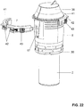
- the support surface 7 on the building side can be designed in various ways. According to a first example in the Figures 18 to 21 is shown, the support surface 7 can be part of the building. After a second example that is in the Figures 22 to 25 is shown, the building-side support surface 7 is part of a holding element 39.
- connection arrangement 1 According to the invention the structure of the connection arrangement 1 according to the invention will now be explained in more detail according to a possible embodiment.
- the bearing area 4 of the tube 2 has at least two bearing points 8 arranged at a distance from one another in the direction of the tube axis R.
- three bearing points 8 are arranged.
- the distances between the bearing points 8 are irregular. However, the intervals can also be regular. It is also conceivable to arrange additional bearings.
- the bearing points 8 are in the form of grooves 10.
- the grooves 10 extend from the outside into the tube 2.
- a plurality of grooves 10 are arranged on the circumference of each bearing point 8.
- the grooves 10 extend only over a partial area of the pipe circumference of the pipe 2.
- 4 grooves 10 are arranged for each bearing point 8.
- connection element 5 also has a bearing point 9.
- the bearing point 9 of the connection element 5 is part of a bearing point ring 11 which is supported on a carrier ring 12.
- the bearing points 9 of the bearing point ring 11 on the connection element side engage in the grooves 10 of the pipe-side bearing point 8.
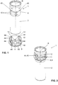
- the carrier ring 12 is a separately formed element from the bearing ring 11, which, as in FIG Figures 1 and 2 shown, can be connected to the tube 2 in a correspondingly displaceable manner.
- the carrier ring 12 has guides 44 which cooperate with corresponding cams 45 on the tube 2 so that they cannot rotate.
- the engagement of Guides 44 together with the cams 45 is in the Figure 2 shown in more detail.
- the guides 44 are delimited in the upper area by spring bars 54, which simplify the assembly of the carrier ring 12 on the tube 2.
- the bearing ring 11 is movably supported in a circumferential guide groove 55 on the carrier ring 12.
- the bearing is such that the said force can be transmitted from the pipe via the bearing ring 11 to the carrier ring 12.
- the bearing ring 11 is preferably designed in two parts, the two parts of the bearing ring 11 being connected to one another via a latching connection 46.
- the latching connection 46 is arranged at the end of the respective part.
- the bearing point 9 of the connection element 5 is designed to be movable from a contact position away from the pipe 2 into an adjustment position and from the adjustment position into the contact position towards the pipe 2.
- the contact position is shown.
- the bearing point 9 of the connection element 5 engages in the bearing point 8 of the tube 2, so that the weight force can be transmitted from the tube 2 via the engagement from the bearing point 8 into the bearing point 9.
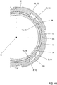
- the contact layer continues in the cross section of the Figure 9 shown.
- the bearing point 8 of the connection element 5 is in the setting position.
- the engagement between the connection element-side bearing point 9 and the pipe-side bearing point 8 is correspondingly canceled.
- the tube 2 can be displaced relative to the connection element 5, such that the bearing point 9 on the connection element side can engage in another of the bearing points 8 on the tube 2 on the tube side.
- connection element-side bearing point 9 In the contact position, the connection element-side bearing point 9 is in stable contact with one of the at least two tube-side bearing points 8. The bearing points 8, 9 engage firmly in one another, so that the tube 2 can no longer be displaced relative to the connection element 5. In the setting position, the connection-side bearing point 9 is not in contact with the at least two pipe-side bearing points 8.
- the displaceability between pipe 2 and connection element 5 has the advantage that the position of the upper pipe end 35 with respect to the support surface 7 on the building side or with respect to the flange surface 6 can be adjusted accordingly.
- the connection element 5 further comprises a housing 22 and corresponding sound decoupling elements 23.
- the flange surface 6 is part of the housing 22.
- the bearing point 9 on the connection element side is connected to the housing 22 via at least one sound decoupling element 23.
- two sound decoupling elements 23 are arranged, which are spaced apart from one another in the direction of the pipe axis R. Due to the arrangement of the sound decoupling elements 23, the carrier ring 12 is connected to the housing 22 in such a way that no structure-borne sound can be introduced from the pipe 2 into the building. The weight of the pipe 2 is introduced into the housing 22 via the sound decoupling elements 23.
- Each of the sound decoupling elements 23 is designed in two parts. Each part of the sound decoupling element 23 is semicircular when viewed in cross section and surrounds approximately half of the pipe circumference. The respective parts of the sound decoupling elements 23 are designed to be identical to one another.
- the sound decoupling elements 23 are mounted on receptacles 24 on the carrier ring 12. In this case, the sound decoupling elements 23 surround the carrier ring 12 on the circumferential side at least partially or here essentially completely.
- the upper of the two sound decoupling elements bears the reference symbol 23a and rests on a surface 25a protruding from the carrier ring 12.
- the lower of the sound decoupling elements bears the reference symbol 23b and rests on a surface 25b protruding from the carrier ring 12.
- the upper sound decoupling element 23a rests on a surface 26a protruding from the housing 22.
- the lower sound decoupling element 23b rests on a surface 26b protruding from the housing 22.
- the lower sound decoupling element 23b rests on a retaining ring 27 on the sound decoupling element 23b.
- connection arrangement 1 with the housing 22 closed is shown. It can be clearly seen here that the housing 22 consists of two housing shells 28 which are connected to one another.
- the tube 2 is here in connection with the bearing point 9 on the connection element side via the bearing point 8 on the tube side.
- the force is transmitted to the carrier ring 12 via the bearing ring 11.
- the force is then transmitted from the carrier ring 12 via the sound decoupling element 23a, 23b to the corresponding surfaces 26a, 26b on the housing 22.
- the sound decoupling elements 23a, 23b form the only contact between the bearing ring 11 or the carrier ring 12 and the housing 22, which has the flange surface 6. This means that vibrations from the pipe are not transmitted to the housing 22 or to the flange surface 6. This prevents sound from being transmitted from the pipe to the building.
- FIG 7 an exploded view is shown.
- a part of the bearing ring 11 and an actuating lever 17 with which the bearing ring 11 can be operated are shown spaced apart from the rest of the connection element 5.
- the bearing ring 11 has an angularly inclined surface 19.
- An actuator section 18 of an actuating lever 17 engages in this angularly inclined surface 19.
- the bearing point 9 on the connection element side is in engagement with the bearing point 8 on the pipe side.
- the corresponding bearing tabs 13 engage in the groove 10.
- the bearing tabs 13 are spring-loaded bearing tabs and protrude from the bearing ring 11 accordingly, which is in the Figure 9 can be recognized well.
- the actuating lever 17 When the actuating lever 17 is actuated via the actuating section 20, the actuating lever 17 is pivoted accordingly, as well as in FIG Figure 10 shown.
- the actuator section 18 strikes the angularly inclined surface 19 on the bearing ring 11 and thereby pivots the bearing ring 11 relative to the carrier ring 12.
- the pivoting of the bearing ring 11 is in the Figure 11 shown.
- the bearing straps 13 also have surfaces 16 which are inclined at an angle and which are located on an edge region 15 of an opening 14 in the carrier ring 11. By pivoting the bearing ring 11 relative to the carrier ring 12, the bearing tabs 13 are then moved radially outward, which in the Figure 11 will be shown.
- the bearing ring 11 With further advancement of the actuating lever 17, the bearing ring 11 is advanced further, as well as into the Figures 12 and 13th shown.
- the bearing tabs 13 are accordingly moved out of the groove 10 on the tube 2 and slide into the opening 14 on the carrier ring 13, whereby the bearing point 9 with its bearing tabs 13 is in the corresponding setting position.
- the tube 2 can be moved relative to the connection element 5.
- the reset of the bearing ring 11 after actuation by the actuating lever 17 can take place in various ways.
- the operating lever 17 is back in its starting position, as well as in the Figure 8 and 9 shown, moved.
- the actuator section 18 disengages from the angularly inclined surface 19.
- a corresponding spring element then restores the bearing ring 11 so that the tube-side bearing 8 engages in the connection-side bearing 9 accordingly.
- the reset can also take place through the bearing bracket 13 itself. For example, by a corresponding shape of the bearing bracket 13.
- the connection arrangement 1 also has a fire protection element 30.
- the fire protection element 30 and its arrangement is based on Figures 14 to 17 explained in more detail.
- the fire protection element 30 comprises an intumescent jacket 31 which is mounted in a metal cage 32.
- the fire protection element 30 is connected to the connection element 5 via two metal brackets 33.
- the metal brackets 33 protrude through the housing 22 and are in contact with the flange surface 6 with a stop section 32 in the upper region.
- the stop section 34 extends in a direction transverse to the pipe axis over the entire cross section of the flange surface 6.
- the metal brackets 33 have a receiving structure 47 downwards, which serves to support the metal cage 32.
- the receiving structure 47 is designed as a type of bayonet lock. Pins 48 on metal cage 32 engage in receiving structure 47.
- the metal cage 32 has various openings 49 through which the intumescent material of the intumescent jacket 31 can swell in the event of a fire, so that the cross-section of the space between the building opening 3 and the pipe 2 accordingly the intumescent material is foamed.
- the mounting of the metal cage 32 on the receiving structure 47 is shown in greater detail.
- the pin 48 is shown in different positions.
- the fire protection element 30 is moved in the direction of the pipe axis and then the fire protection element 30 is pivoted about the pipe axis R so that the pin 48 comes to rest in the receiving structure 47.
- a first structural protection is arranged in the area of the upper pipe end 35.
- the first structural protection bears the reference number 36 and essentially protects the pipe 2 and the interior of the connection element 5 from contamination.
- connection arrangement 1 with the connection element 5 and the pipe 2 is shown shortly before installation in the building opening 3.
- the connection arrangement 1 is mounted in the building opening 3 in the direction of the arrow P.
- the entire arrangement carries a further structural protection element 38, which extends in the direction of a pipe region 37.
- the further structural protection element 38 is connected to the fire protection element 30.
- connection element 5 in the building opening 3 is then shown.
- brackets 50 are provided, which are connected to the building and act on the flange surface 6 of the connection element 5. Securing with the clamp is a first type of mechanical fastening.
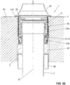
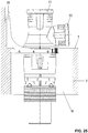
- the Figure 20 shows a corresponding sectional view of the installation position.
- the two building blocks 36, 38 are also shown. These can be removed after the assembly is successful.
- a fitting 51 is shown which is in contact with the upper end of the tube 35.
- the connection piece 51 which bears the reference number 52, are brought correspondingly close to the storage area 4 of the building. In this way, for example, the gradient of a pipe connected to the branch 52 can be used.
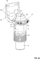
- connection element 5 is shown in the Figures 22 to 25.
- the system further comprises a holding element 39.
- the holding element 39 comprises a fastening bracket 40 for fastening the holding element 39 to a wall W and a bearing part 41 Bearing part 41 is in a corresponding connection with the mounting bracket 40.
- the connection is a longitudinal guide 42. That is to say, the bearing part 41 can be displaced with the connection element 5 relative to the fastening bracket 40 in the longitudinal guide.
- a latching means 43 is also arranged in the region of the longitudinal guide. The position between the bearing part 41 and the fastening bracket 40 can be locked with the latching means 43.
- the locking means 43 is pushed into the longitudinal guide and forms a clamping effect between the bearing part 41 and the fastening bracket 40 in the longitudinal guide.
- the fastening bracket 40 For fastening to a wall, the fastening bracket 40 has a multiplicity of fastening openings 53 through which screw means can be passed.
- the connection arrangement 1 With the system according to the Figures 22 to 25 it will be like in the Figure 25 shown, enables a more flexible application for the connection arrangement 1 is made possible.
- connection arrangement 1 and the building opening 3 can be filled with mortar M.
- connection arrangement 30th Fire protection element 2 pipe 31 Intumescent jacket 3rd Building opening 32 Metal cage 4th storage area 33 Metal bracket 5 Connection element 34 Stop section 6th Flange surface 35 upper end of the pipe 7th Support surface on the building side 36 Building protection 8th pipe-side bearing 37 Pipe area 9 bearing point on the connection element side 38 Building protection 39 Retaining element 10 groove 40 Mounting bracket 11 Bearing ring 41 Bearing part 12th Carrier ring 42 Longitudinal guide 13th Bearing straps 43 Locking means 14th breakthrough 44 guides 15th Edge area 45 cam 16 angled surface 46 Locking connection 17th Operating lever 47 Recording structure 18th Actuator section 48 Cones 19th angled surface 49 Breakthroughs 20th Operating section 50 Bracket 21 Locking element 51 Connector 22nd casing 52 Branch 23 Sound decoupling element 53 Mounting holes 24 Recordings 54 Spring bar 25th area 55 Guide groove 26th area R. Pipe axis 27 Retaining ring S. Swivel axis 28 Housing shells M. mortar 29 Locking elements
Landscapes
- Engineering & Computer Science (AREA)
- General Engineering & Computer Science (AREA)
- Mechanical Engineering (AREA)
- Quick-Acting Or Multi-Walled Pipe Joints (AREA)
Description
Die vorliegende Erfindung betrifft eine Verbindungsanordnung zur Verbindung eines Rohrs mit einem Gebäude im Bereich einer Gebäudeöffnung nach dem Oberbegriff von Anspruch 1.The present invention relates to a connection arrangement for connecting a pipe to a building in the area of a building opening according to the preamble of
Aus dem Stand der Technik sind Halteelemente für Rohre, welche sich durch Öffnungen in Wänden oder Böden hindurch erstrecken, bekannt.Holding elements for pipes which extend through openings in walls or floors are known from the prior art.
Zum Beispiel zeigt die
Die
Das Rohr wird in einer Ausführungsform über einen Lagerring in der Öffnung gehalten, wobei der Lagerring zwischen einem Flansch des Rohrs und einem Absatz der Öffnung gehalten ist. In einer anderen Ausführungsform ist in der Öffnung eine Hülse eingesetzt, welche ebenfalls einen Absatz für die Kontaktierung des Lagerrings aufweist.In one embodiment, the tube is held in the opening via a bearing ring, the bearing ring being held between a flange of the tube and a shoulder of the opening. In another embodiment, a sleeve is inserted in the opening, which likewise has a shoulder for contacting the bearing ring.
Diese Art von Lagerung weist einige Nachteile auf. Der Lagerring muss, um die Position des Rohrs zu halten, eine gewisse Härte aufweisen, was dazu führt, dass akustischen Schwingungen über den Lagerring auf den Boden übertragen werden. Die Gewichtskraft führt bei diesen Ausführungsformen zu einem wirksamen Drehmoment, weil die Gewichtskraft zu einer Drehbewegung um den Haltepunkt führen kann. Die Halterung muss daher aus statischen Gründen über ein Mindestmass an integraler Festigkeit verfügen, was zwangsläufig zu einer Schallkopplung zwischen Bauteil und Baukörper fuhrt.This type of storage has some disadvantages. The bearing ring must have a certain hardness in order to hold the position of the pipe, which means that acoustic vibrations are transmitted to the ground via the bearing ring. In these embodiments, the weight force leads to an effective torque, because the weight force can lead to a rotary movement around the holding point. For static reasons, the bracket must therefore have a minimum degree of integral strength, which inevitably leads to a sound coupling between component and structure.
Zudem ist die mechanische Lagerung innerhalb der Öffnung relativ aufwändig, weil einerseits eine Stufenbohrung im Beton hergestellt werden muss, oder andererseits eine Hülse in Öffnung eingesetzt werden muss.In addition, the mechanical mounting within the opening is relatively complex, because on the one hand a stepped bore has to be made in the concrete, or on the other hand a sleeve has to be inserted in the opening.
Andere aus dem Stand der Technik bekannte Ausführungsformen verwenden stets Rohrschellen zur Befestigung des Rohres. Somit werden Körperschallbrücken gebildet, was sich negativ auf den Schallpegel auswirkt.Other embodiments known from the prior art always use pipe clamps for fastening the pipe. Structure-borne sound bridges are thus formed, which has a negative effect on the sound level.
Aus der
Die oben genannten Halteelemente weisen weiter den Nachteil auf, dass deren Einstellbarkeit stark limitiert ist.The above-mentioned holding elements also have the disadvantage that their adjustability is severely limited.
Ausgehend von diesem Stand der Technik liegt der Erfindung eine Aufgabe zugrunde, eine Verbindungsanordnung zur Verbindung eines Rohrs mit einem Gebäude im Bereich einer Gebäudeöffnung anzugeben, welche die Nachteile des Standes der Technik überwindet. Insbesondere ist es eine bevorzugte Aufgabe, eine Verbindungsanordnung anzugeben, welche bezüglich verschiedener Einbausituation flexibler einsetzbar ist.Proceeding from this prior art, the invention is based on an object of specifying a connection arrangement for connecting a pipe to a building in the area of a building opening which overcomes the disadvantages of the prior art. In particular, it is a preferred object to specify a connection arrangement which can be used more flexibly with regard to different installation situations.
Diese Aufgabe wird durch den Gegenstand von Anspruch 1 gelöst. Demgemäss umfasst eine Verbindungsanordnung zur Verbindung eines Rohrs mit einem Gebäude im Bereich einer Gebäudeöffnung ein durch die Gebäudeöffnung hindurchzuführendes Rohr mit einem aussenseitig angeordneten Lagerbereich und ein Anschlusselement, welches mit dem Lagerbereich des Rohrs verbindbar ist und welches eine Flanschfläche aufweist, mit welcher das Anschlusselement auf einer gebäudeseitigen Auflagefläche lagerbar ist. Der Lagerbereich des Rohrs weist mindestens zwei in Richtung der Rohrachse beabstandet zueinander angeordnete Lagerstellen auf. Weiter weist das Anschlusselement eine Lagerstelle auf, wobei die besagte Lagerstelle von einer Kontaktlage vom Rohr weg in eine Einstelllage und von der Einstelllage in die Kontaktlage auf das Rohr hin bewegbar ausgebildet ist. In der Kontaktlage ist die anschlusselementseitige Lagerstelle mit einer der mindestens zwei rohrseitigen Lagerstellen in einen tragfähigen Kontakt bringbar. In der Einstelllage ist die anschlussseitige Lagerstelle nicht im Kontakt mit den mindestens zwei rohrseitigen Lagerstellen, so dass das Rohr in Richtung der Rohrachse bezüglich des Anschlusselementes verschiebbar ist.This object is achieved by the subject matter of
Durch die Einstellbarkeit der Lage zwischen Rohr und Anschlusselement ergeht der Vorteil, dass die Lage des Rohrendes bezüglich der Flanschfläche und somit auch bezüglich der gebäudeseitigen Einbaukonfiguration einstellbar ist. In Einbaulage liegt das Anschlusselement durch den Kontakt zwischen der Flanschfläche und der gebäudeseitigen Auflagefläche ortsfest in der Gebäudeöffnung. Durch die Verschiebbarkeit des Rohrs relativ zum Anschlusselement wird erreicht, dass das Rohrende relativ zur gebäudeseitigen Auflagefläche verschoben werden kann. Das heisst, der Abstand zwischen dem oberen Rohrende und der gebäudeseitigen Auflagefläche wird einstellbar und kann an die gewünschte Einbausituation angepasst werden.The adjustability of the position between the pipe and the connection element has the advantage that the position of the pipe end with respect to the flange surface and thus also with respect to the installation configuration on the building side can be adjusted. In the installed position, the connection element is fixed in the building opening due to the contact between the flange surface and the support surface on the building side. As a result of the displaceability of the pipe relative to the connection element, it is achieved that the pipe end can be displaced relative to the support surface on the building side. This means that the distance between the upper end of the pipe and the supporting surface on the building side is adjustable and can be adapted to the desired installation situation.
Unter der Ausdrucksweise eines "tragfähigen Kontaktes" wird verstanden, dass der tragfähige Kontakt derart ist, dass mindestens eine des Eigengewichts des Rohrs entsprechende Gewichtskraft über die Lagerstelle in das Anschlusselement einleitbar ist.The expression "load-bearing contact" is understood to mean that the load-bearing contact is such that at least one weight force corresponding to the weight of the pipe can be introduced into the connection element via the bearing point.
Vorzugsweise sind die mindestens zwei rohrseitigen Lagerstellen als Nuten ausgebildet. Vorzugsweise sind pro Lagerstelle mehrere Nuten, die sich nur über einen Teilbereich des Rohrumfangs erstrecken, angeordnet. Alternativerweise ist pro Lagerstelle eine vollständig um den Rohrumfang umlaufende Nute angeordnet.The at least two pipe-side bearing points are preferably designed as grooves. A plurality of grooves, which extend only over a partial area of the pipe circumference, are preferably arranged per bearing point. Alternatively, a groove running completely around the pipe circumference is arranged for each bearing point.
Die Nuten von zwei benachbart liegenden rohrseitigen Lagerstellen liegen in Richtung der Rohrachse in einem Abstand zueinander.The grooves of two adjacent pipe-side bearing points are at a distance from one another in the direction of the pipe axis.
Die Nuten sind vorzugsweise integral am Rohr angeformt und liegen insbesondere in einem Endbereich des Rohrs. Der Endbereich kann bezüglich den restlichen Teilen des Rohrs einen vergrösserten Durchmesser aufweisen.The grooves are preferably formed integrally on the pipe and are in particular in an end region of the pipe. The end region can have an enlarged diameter with respect to the remaining parts of the tube.
Die anschlusselementseitige Lagerstelle ist Teil eines Lagerstellenrings, der an einem zum Anschlusselement gehörenden Trägerring um den Umfang des Trägerrings verschwenkbar angeordnet ist. Durch die Verschwenkung ist die anschlussseitige Lagerstelle zwischen der Kontaktlage und der Einstelllage hin und her bewegbar.The bearing point on the connection element side is part of a bearing point ring which is arranged on a carrier ring belonging to the connection element so as to be pivotable around the circumference of the carrier ring. As a result of the pivoting, the connection-side bearing point can be moved back and forth between the contact position and the setting position.
Der Trägerring ist Teil des Anschlusselementes und ist in diesem gelagert. Besonders bevorzugt ist der Trägerring wie unten beschrieben gelagert. Andere Arten der Lagerung sind auch denkbar.The carrier ring is part of the connection element and is mounted in it. The carrier ring is particularly preferably mounted as described below. Other types of storage are also conceivable.
Der Lagerstellenring ist vorzugsweise auf der Aussenseite des Trägerrings gelagert. Die Lagerung ist vorzugsweise derart, dass der Lagerstellenring relativ zum Trägerring verschwenkbar ist und dass die oben beschriebene Kraft vom Lagerstellenring in den Trägerring einleitbar ist.The bearing ring is preferably mounted on the outside of the carrier ring. The mounting is preferably such that the bearing ring can be pivoted relative to the carrier ring and that the above-described force can be introduced from the bearing ring into the carrier ring.
Der Lagerstellenring ist vorzugsweise aus mindestens zwei Ringsegmenten zusammengesetzt, welche über eine Rastverbindung miteinander in Verbindung stehen.The bearing ring is preferably composed of at least two ring segments which are connected to one another via a latching connection.
Vorzugsweise wird die anschlusselementseitige Lagerstelle durch mehrere vom Lagerstellenring abstehende Lagerlaschen bereitgestellt, welche durch einen Durchbruch im Trägerring zu den rohrseitigen Lagerstellen hindurchragen. Die Lagerlaschen sind vorzugsweise gefedert ausgebildet. Die Lagerlaschen und/oder der Randbereich des Durchbruches weist eine winklig geneigte Fläche auf, welche derart winklig geneigt ist, dass bei einer Bewegung des Lagerstellenrings relativ zum Trägerring die Lagerlaschen von der Kontaktlage in die Einstelllage in den Durchbruch hinein bewegt werden. Die Lagerlaschen werden somit vom Rohr weg bewegt.The bearing point on the connection element side is preferably provided by a plurality of bearing tabs which protrude from the bearing point ring and which protrude through an opening in the carrier ring to the bearing points on the pipe side. The bearing brackets are preferably designed to be sprung. The bearing tabs and / or the edge region of the opening has an angled surface which is inclined at an angle such that when the bearing ring is moved relative to the carrier ring, the bearing tabs are moved from the contact position into the setting position into the opening. The bearing brackets are thus moved away from the pipe.
Vorzugsweise umfasst die Verbindungsanordnung weiterhin einen Betätigungshebel, welcher an einer Schwenkachse am Anschlusselement gelagert ist, wobei der Betätigungshebel mit einem Aktuatorabschnitt an eine winklig geneigte Fläche am Lagerstellenring eingreift und mit einem Betätigungsabschnitt um die Schwenkachse verschwenkbar ist, wobei bei einer Verschwenkung des Betätigungshebels der Aktuatorabschnitt derart zur winklig geneigten Fläche bewegt wird, dass der Lagerstellenring relativ zum Trägerring um die Rohrachse von der Kontaktlage in die Einstelllage bewegt wird.The connection arrangement preferably further comprises an actuating lever which is mounted on a pivot axis on the connection element, the actuating lever engaging with an actuator section on an angularly inclined surface on the bearing ring and being pivotable with an actuating section about the pivot axis, the actuator section being pivotable when the actuating lever is pivoted is moved to the angularly inclined surface that the bearing ring relative to the carrier ring around the pipe axis from the contact position into the Setting position is moved.
Die Ausdrucksweise, dass der Betätigungshebel am Anschlusselement gelagert ist, ist so zu verstehen, dass der Betätigungshebel an einem Element oder Teil des Anschlusselementes gelagert ist. Dieses Element oder Teil steht, abgesehen von der Verschwenkbarkeit um die Verschwenkachse fest zum Trägerring bzw. zum Anschlusselement. Das heisst, dass der Lagerstellenring relativ zum Betätigungshebel bewegbar ausgebildet ist.The expression that the actuating lever is mounted on the connection element is to be understood as meaning that the actuation lever is mounted on an element or part of the connection element. This element or part, apart from being able to pivot about the pivot axis, is fixed to the carrier ring or to the connection element. This means that the bearing ring is designed to be movable relative to the actuating lever.
Vorzugsweise rastet der Betätigungshebel in mindestens einer seiner Endlagen an einem Rastelement ein. Hierdurch wird seine Position gesichert. Vorzugsweise rastet der Betätigungshebel in beiden Endlagen ein.The actuating lever preferably engages in at least one of its end positions on a locking element. This will secure its position. The actuating lever preferably engages in both end positions.
Vorzugsweise umfasst das Anschlusselement ein Gehäuse. Die Flanschfläche ist dabei Teil des Gehäuses. Die anschlusselementseitige Lagerstelle ist über mindestens ein Schallentkoppelungselement im Gehäuse gelagert.The connection element preferably comprises a housing. The flange surface is part of the housing. The mounting point on the connection element side is mounted in the housing via at least one sound decoupling element.
Das mindestens eine Schallentkoppelungselement ist demnach zwischen dem Anschlusselement, das mit dem Rohr in Verbindung steht, und dem Gehäuse angeordnet. Die Schallübertragung vom Rohr auf die Flanschfläche und somit auf das Gebäude wird demnach durch das mindestens eine Schallentkoppelungselement unterbunden.The at least one sound decoupling element is accordingly arranged between the connection element, which is connected to the pipe, and the housing. The sound transmission from the pipe to the flange surface and thus to the building is accordingly prevented by the at least one sound decoupling element.
Vorzugsweise steht das Anschlusselement ausschliesslich über das mindestens eine Schallentkoppelungselement mit dem Gehäuse in Verbindung.The connection element is preferably connected to the housing exclusively via the at least one sound decoupling element.
Unter der Ausdrucksweise Schallentkoppelungselement wird ein Element verstanden, welches vorzugsweise aus einem weichen Material ist und elastische Eigenschaften aufweist. Besonders bevorzugt ist das Schallentkoppelungselement ein Dämpfer aus Gummi oder Kunststoff.The expression sound decoupling element is understood to mean an element which is preferably made of a soft material and has elastic properties. The sound decoupling element is particularly preferably a damper made of rubber or plastic.
Vorzugsweise ist das mindestens eine Schallentkoppelungselement an Aufnahmen am Trägerring gelagert. Die Schallentkoppelungselemente umgeben den Trägerring umfangsseitig mindestens teilweise oder vollständig. Vorzugsweise besteht jedes der Schallentkoppelungselemente vorzugsweise aus mindestens zwei Teilen, wobei sich jeder Teil im Wesentlichen um einen gleichen Teil der Umfangsseite des Trägerrings erstreckt. Bei einem zweiteiligen Schallentkoppelungselement wird die Montage desselben vereinfacht.The at least one sound decoupling element is preferably mounted on receptacles on the carrier ring. The sound decoupling elements surround the carrier ring at least partially or completely on the circumferential side. Preferably each of the Sound decoupling elements preferably made up of at least two parts, each part extending essentially around an equal part of the circumferential side of the carrier ring. In the case of a two-part sound decoupling element, the assembly of the same is simplified.
Vorzugsweise ist das Schallentkoppelungselement aus genau zwei Teilen ausgebildet, wobei sich jeder der Teile im Wesentlichen hälftig um den Umfang des Trägerrings erstreckt.The sound decoupling element is preferably formed from exactly two parts, each of the parts extending essentially halfway around the circumference of the carrier ring.
Vorzugsweise sind mehrere Schallentkoppelungselemente in Richtung der Rohrachse beabstandet am Trägerring zueinander angeordnet, wobei eines der Schallentkoppelungselemente an einer von Trägerring abstehenden Fläche und an einer von Gehäuse abstehenden Fläche aufliegen und wobei ein anderes der Schallentkoppelungselemente an einer von Trägerring abstehenden Fläche und an einer von Gehäuse abstehenden Fläche, insbesondere über einen Haltering, aufliegen.A plurality of sound decoupling elements are preferably arranged at a distance from one another on the carrier ring in the direction of the pipe axis, one of the sound decoupling elements resting on a surface protruding from the carrier ring and on a surface protruding from the housing and another of the sound decoupling elements resting on a surface protruding from the carrier ring and on a protruding surface from the housing Surface, in particular over a retaining ring.
Vorzugsweise umfasst das Gehäuse mindestens zwei Gehäuseschalen, welche Gehäuseschalen mit Rastelementen miteinander verbindbar sind. Die Ausbildung des Gehäuses mit zwei oder mehr Gehäuseschalen hat den Vorteil, dass die im Gehäuse liegenden Element in einer der Gehäuseschalen aufbaubar sind und dass anschliessend die andere(n) der Gehäuseschalen montiert werden können.The housing preferably comprises at least two housing shells, which housing shells can be connected to one another with latching elements. The design of the housing with two or more housing shells has the advantage that the elements lying in the housing can be built up in one of the housing shells and that the other (s) of the housing shells can then be mounted.
Vorzugsweise ist der Betätigungshebel am Gehäuse gelagert und ist zum Gehäuse verschwenkbar.The actuating lever is preferably mounted on the housing and can be pivoted relative to the housing.
Der Betätigungshebel ist vorzugsweise derart am Gehäuse angeordnet, dass sich der Betätigungshebel nur dann im Eingriff mit dem Lagerstellenring befindet, wenn der Betätigungshebel entsprechend betätigt bzw. verschwenkt wird. Das heisst, wenn die Lagerstellen in der Kontaktlage liegen, also im Eingriff miteinander sind, ist der Betätigungshebel nicht in Kontakt mit dem Lagerstellenring. Hierdurch kann eine Schallentkoppelung erreicht werden.The actuating lever is preferably arranged on the housing in such a way that the actuating lever is only in engagement with the bearing ring when the actuating lever is actuated or pivoted accordingly. This means that when the bearing points are in the contact position, that is to say they are in engagement with one another, the actuating lever is not in contact with the bearing point ring. Sound decoupling can hereby be achieved.
Vorzugsweise umfasst die Verbindungsanordnung gegenüber der Flanschfläche ein Brandschutzelement, wobei das Brandschutzelement ein um das Rohr umlaufender Intumeszenzmantel, der in einem Metallkäfig gelagert, umfasst. Der Metallkäfig wird über Metallbügel, die sich durch die Verbindungsanordnung hindurch bis zur Flanschfläche erstrecken und mit einem Anschlagsabschnitt auf der Flanschfläche aufliegen, gehalten.Preferably, the connection arrangement comprises one opposite the flange surface Fire protection element, wherein the fire protection element comprises an intumescent jacket which runs around the pipe and which is mounted in a metal cage. The metal cage is held by means of metal brackets which extend through the connecting arrangement to the flange surface and which rest with a stop section on the flange surface.
Vorzugsweise erstrecken sich die Anschlagsabschnitte quer zur Rohrachse gesehen im Wesentlichen vollständig über die Flanschfläche. Das heisst, dass die Anschlagsabschnitte der Metallbügel immer derart liegen, dass der Anschlagsabschnitt in Kontakt mit der Gebäudefläche kommt, welche sich der Gebäudeöffnung anschliesst.The stop sections preferably extend essentially completely over the flange surface when viewed transversely to the pipe axis. This means that the stop sections of the metal brackets always lie in such a way that the stop section comes into contact with the building surface which adjoins the building opening.
Vorzugsweise sind mindestens zwei Metallbügel bezüglich der Rohrachse gegenüber einander angeordnet.Preferably, at least two metal brackets are arranged opposite one another with respect to the pipe axis.
Das Brandschutzelement schliesst sich vorzugweise dem Gehäuse an. Vorzugsweise steht das Brandschutzelement vorzugsweise über eine Art Bajonettverschluss mit den Metallbügeln in Verbindung.The fire protection element preferably adjoins the housing. The fire protection element is preferably connected to the metal brackets via a type of bayonet lock.
Vorzugsweise ist im Bereich des oberen Rohrendes ein den Rohrquerschnitt und den offenen Querschnitt des Anschlusselementes verschliessenden Bauschutz vorgesehen. Alternativerweise oder zusätzlich ist im Rohrbereich ein Bauschutz vorgesehen, der sich entlang des Rohrs erstreckt.In the area of the upper end of the pipe, a structural protection that closes the pipe cross-section and the open cross-section of the connection element is preferably provided. Alternatively or in addition, a building protection is provided in the pipe area, which extends along the pipe.
Ein System umfasst eine Verbindungsanordnung nach obiger Beschreibung und ein Halteelement. Das Halteelement umfasst einen Befestigungsbügel zur Befestigung des Halteelementes an einer Wand und ein Lagerteil zur Lagerung des Anschlusselements, wobei der Befestigungsbügel und das Lagerteil über eine Längsführung miteinander in Verbindung stehen. Die gebäudeseitige Auflagefläche wird hier durch das Halteelement bereitgestellt.A system comprises a connection arrangement as described above and a retaining element. The retaining element comprises a fastening bracket for fastening the retaining element to a wall and a bearing part for mounting the connection element, the fastening bracket and the bearing part being connected to one another via a longitudinal guide. The support surface on the building side is provided here by the holding element.
Vorzugsweise umgibt das Lagerteil das Anschlusselement im Wesentlichen vollständig und steht mit der Flanschfläche in Kontakt.The bearing part preferably surrounds the connection element essentially completely and is in contact with the flange surface.
Vorzugsweise weist die Längsführung Rastmittel auf, so dass die Lage zwischen Lagerteil und Befestigungsbügel arretiert werden kann.The longitudinal guide preferably has latching means so that the position between the bearing part and mounting bracket can be locked.
Weitere Ausführungsformen sind in den abhängigen Ansprüchen angegeben.Further embodiments are given in the dependent claims.
Bevorzugte Ausführungsformen der Erfindung werden im Folgenden anhand der Zeichnungen beschrieben, die lediglich zur Erläuterung dienen und nicht einschränkend auszulegen sind. In den Zeichnungen zeigen:
- Fig. 1
- eine Explosionsdarstellung von Teilen einer Verbindungsanordnung zur Verbindung eines Rohrs mit einem Gebäude im Bereich einer Gebäudeöffnung;
- Fig. 2
- eine Detailansicht der Verbindungsanordnung nach
Figur 1 ; - Fig. 3
- eine Detailansicht der Verbindungsanordnung nach den vorhergehenden Figuren;
- Fig. 4
- eine Detailansicht der Verbindungsanordnung nach den vorhergehenden Figuren;
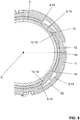
- Fig. 5
- eine perspektivische Ansicht von Teilen der Verbindungsanordnung nach den vorhergehenden Figuren;
- Fig. 6
- eine Schnittdarstellung der Verbindungsanordnung nach den vorhergehenden Figuren;
- Fig. 7
- eine Explosionsdarstellung der Verbindungsanordnung nach den vorhergehenden Figuren;
- Fig. 8
- eine weitere Explosionsdarstellung der Verbindungsanordnung nach den vorhergehenden Figuren;
- Fig. 9
- eine Darstellung eines Teilschnitts quer zur Rohrachse der Verbindungsanordnung nach der
Figur 8 - Fig. 10
- eine weitere Explosionsdarstellung der Verbindungsanordnung nach den vorhergehenden Figuren;
- Fig. 11
- eine Darstellung eines Teilschnitts quer zur Rohrachse der Verbindungsanordnung nach der
Figur 10 ; - Fig. 12
- eine weitere Explosionsdarstellung der Verbindungsanordnung nach den vorhergehenden Figuren;
- Fig. 13
- eine Darstellung eines Teilschnitts quer zur Rohrachse der Verbindungsanordnung nach der
Figur 12 ; - Fig. 14
- eine weitere Explosionsdarstellung der Verbindungsanordnung nach den vorhergehenden Figuren;
- Fig. 15
- eine weitere Darstellung der Verbindungsanordnung nach den vorhergehenden Figuren mit einem Brandschutzelement;
- Fig. 16
- eine weitere Darstellung der Verbindungsanordnung nach der
Figur 15 ; - Fig. 17
- eine weitere Darstellung der Verbindungsanordnung nach den vorhergehenden Figuren mit einem Bauschutzelement;
- Fig. 18
- eine weitere Darstellung der Verbindungsanordnung nach den vorhergehenden Figuren im Zusammenhang mit einer ersten Einbausituation;
- Fig. 19
- eine weitere Darstellung der Einbausituation nach
Figur 18 ; - Fig. 20
- eine Schnittdarstellung der Einbausituation nach
Figur 18 ; - Fig. 21
- eine weitere Darstellung der Einbausituation nach
Figur 18 ; - Fig. 22
- eine weitere Darstellung der Verbindungsanordnung nach den vorhergehenden Figuren im Zusammenhang mit einer zweiten Einbausituation;
- Fig. 23
- eine weitere Darstellung der Einbausituation nach
Figur 22 ; - Fig. 24
- eine weitere Darstellung der Einbausituation nach
Figur 22 ; und - Fig. 25
- eine weitere Darstellung der Einbausituation nach
Figur 22 .
- Fig. 1
- an exploded view of parts of a connection arrangement for connecting a pipe to a building in the area of a building opening;
- Fig. 2
- a detailed view of the connection arrangement according to
Figure 1 ; - Fig. 3
- a detailed view of the connection arrangement according to the preceding figures;
- Fig. 4
- a detailed view of the connection arrangement according to the preceding figures;
- Fig. 5
- a perspective view of parts of the connecting arrangement according to the preceding figures;
- Fig. 6
- a sectional view of the connection arrangement according to the preceding figures;
- Fig. 7
- an exploded view of the connection arrangement according to the preceding figures;
- Fig. 8
- a further exploded view of the connection arrangement according to the preceding figures;
- Fig. 9
- a representation of a partial section transversely to the pipe axis of the connection arrangement according to FIG
Figure 8 ; - Fig. 10
- a further exploded view of the connection arrangement according to the preceding figures;
- Fig. 11
- a representation of a partial section transversely to the pipe axis of the connection arrangement according to FIG
Figure 10 ; - Fig. 12
- a further exploded view of the connection arrangement according to the previous figures;
- Fig. 13
- a representation of a partial section transversely to the pipe axis of the connection arrangement according to FIG
Figure 12 ; - Fig. 14
- a further exploded view of the connection arrangement according to the preceding figures;
- Fig. 15
- a further representation of the connection arrangement according to the preceding figures with a fire protection element;
- Fig. 16
- a further representation of the connection arrangement according to the
Figure 15 ; - Fig. 17
- a further representation of the connection arrangement according to the preceding figures with a structural protection element;
- Fig. 18
- a further illustration of the connection arrangement according to the preceding figures in connection with a first installation situation;
- Fig. 19
- another illustration of the installation situation
Figure 18 ; - Fig. 20
- a sectional view of the installation situation
Figure 18 ; - Fig. 21
- another illustration of the installation situation
Figure 18 ; - Fig. 22
- a further illustration of the connection arrangement according to the preceding figures in connection with a second installation situation;
- Fig. 23
- another illustration of the installation situation
Figure 22 ; - Fig. 24
- another illustration of the installation situation
Figure 22 ; and - Fig. 25
- another illustration of the installation situation
Figure 22 .
In den Figuren wird eine Verbindungsanordnung 1 zur Verbindung eines Rohrs 2 mit einem Gebäude im Bereich einer Gebäudeöffnung 3 gezeigt. Die Verbindungsanordnung 1 liegt dabei typischerweise in der Gebäudeöffnung 3. Dabei sichert die Verbindungsanordnung 1 das Rohr 2 zu dem Gebäude.In the figures, a
Die Verbindungsanordnung 1 umfasst ein durch die Gebäudeöffnung 3 hindurchzuführendes Rohr 2 mit einem aussenseitig angeordneten Lagerbereich 4 und ein Anschlusselement 5, welches mit dem Lagerbereich 4 des Rohrs 2 verbindbar ist, und welches eine Flanschfläche 6 aufweist, mit welcher das Anschlusselement 5 auf einer Gebäudeseitigen Auflagefläche 7 lagerbar ist. Das Rohr 2 wird demnach über das Anschlusselement 5 mit dem Gebäude verbunden.The
Die gebäudeseitige Auflagefläche 7 kann verschiedenartig ausgebildet sein. Gemäss einem ersten Beispiel, das in den
Anhand der
In der
Weiter weist auch das Anschlusselement 5 eine Lagerstelle 9 auf. Die Lagerstelle 9 des Anschlusselementes 5 ist in der gezeigten Ausführungsform Teil eines Lagerstellenrings 11, der an einem Trägerring 12 gelagert ist. Die anschlusselementseitigen Lagerstellen 9 des Lagerstellenrings 11 greifen in der gezeigten Ausführungsform in die Nuten 10 der rohrseitigen Lagerstelle 8 ein.The
Der Trägerring 12 ist ein vom Lagerstellenring 11 separat ausgebildetes Element, welches, wie in der
Der Lagerstellenring 11 ist in einer umlaufenden Führungsnut 55 am Trägerring 12 bewegbar gelagert. Die Lagerung ist dabei derart, dass die besagte Kraft vom Rohr über den Lagerstellenring 11 auf den Trägerring 12 übertragbar ist. Der Lagerstellenring 11 ist vorzugsweise zweiteilig ausgebildet, wobei die beiden Teile des Lagerstellenrings 11 über eine Rastverbindung 46 miteinander in Verbindung stehen. Die Rastverbindung 46 ist dabei endseitig vom jeweiligen Teil angeordnet.The bearing
Die Lagerstelle 9 des Anschlusselementes 5 ist von einer Kontaktlage vom Rohr 2 weg in eine Einstelllage und von der Einstelllage in die Kontaktlage auf das Rohr 2 hin bewegbar ausgebildet. In der Schnittdarstellung der
In der Kontaktlage ist die anschlusselementseitige Lagerstelle 9 mit einer der mindestens zwei rohrseitigen Lagerstellen 8 in einem tragfähigen Kontakt. Die Lagerstellen 8, 9 greifen dabei fest ineinander, so dass das Rohr 2 nicht mehr relativ zum Anschlusselement 5 verschoben werden kann. In der Einstelllage ist die anschlussseitige Lagerstelle 9 nicht in Kontakt mit den mindestens zwei rohrseitigen Lagerstellen 8. Dabei kann das Rohr 2 bezüglich des Anschlusselementes 5 in Richtung der Rohrachse R entsprechend verschoben werden. Die Verschiebbarkeit zwischen Rohr 2 und Anschlusselement 5 hat den Vorteil, dass die Lage des oberen Rohrendes 35 bezüglich der gebäudeseitigen Auflagefläche 7 bzw. bezüglich der Flanschfläche 6 entsprechend eingestellt werden kann. In den
Jedes der Schallentkoppelungselemente 23 ist zweiteilig ausgebildet. Jedes Teil des Schallentkoppelungselementes 23 ist im Querschnitt gesehen halbkreisförmig ausgebildet und umgibt in etwa die Hälfte des Rohrumfangs. Die jeweiligen Teile der Schallentkoppelungselemente 23 sind dabei identisch zueinander ausgebildet. Die Schallentkoppelungselemente 23 sind an Aufnahmen 24 am Trägerring 12 gelagert. Dabei umgeben die Schallentkoppelungselemente 23 den Trägerring 12 umfangsseitig mindestens teilweise bzw. hier im Wesentlichen vollständig.Each of the sound decoupling elements 23 is designed in two parts. Each part of the sound decoupling element 23 is semicircular when viewed in cross section and surrounds approximately half of the pipe circumference. The respective parts of the sound decoupling elements 23 are designed to be identical to one another. The sound decoupling elements 23 are mounted on
Das obere der beiden Schallentkoppelungselemente trägt das Bezugszeichen 23a und liegt an einer vom Trägerring 12 abstehenden Fläche 25a auf. Das untere der Schallentkoppelungselemente trägt das Bezugszeichen 23b und liegt an einer vom Trägerring 12 abstehenden Fläche 25b auf. Auf Seiten des Gehäuses 22 liegt das obere Schallentkoppelungselement 23a an einer vom Gehäuse 22 abstehenden Fläche 26a auf. Das untere Schallentkoppelungselement 23b liegt an einer vom Gehäuse 22 abstehenden Fläche 26b auf. In der gezeigten Ausführungsform liegt das untere Schallentkoppelungselement 23b über einem Haltering 27 am Schallentkoppelungselement 23b auf.The upper of the two sound decoupling elements bears the
In der
Anhand der
Bei der
In der
Die Rückstellung des Lagerstellenrings 11 nach Betätigung durch den Betätigungshebel 17 kann auf verschiedene Arten erfolgen. Typischerweise wird der Betätigungshebel 17 wieder in seine Ausgangslage, sowie in der
Weiter weist die Verbindungsanordnung 1 ein Brandschutzelement 30 auf. Das Brandschutzelement 30 und dessen Anordnung wird anhand der
Der Metallkäfig 32 weist verschiedene Durchbrüche 49 auf, durch welche das Intumeszenzmaterial des Intumeszenzmantel 31 im Brandfall aufquellen kann, sodass der Querschnitt des Zwischenraums zwischen Gebäudeöffnung 3 und Rohr 2 entsprechend mit dem Intumeszenzmaterial aufgeschäumt wird.The
In der
In der
In der
In der
Die
In der
In den
Für die Befestigung an einer Wand weist der Befestigungsbügel 40 eine Vielzahl von Befestigungsöffnungen 53 auf, durch welche Schraubenmittel hindurchgeführt werden können. Mit dem System gemäss den
In der
Claims (14)
- Connection arrangement (1) for connecting a pipe (2) to a building in the region of an opening (3) of the building, comprisinga pipe (2) which is to be guided through the opening (3) of the building and which comprises an externally arranged bearing region (4), anda connecting element (5) which is connectable with the bearing region (4) of the pipe (2) and which comprises a flange surface (6), by which the connecting element (5) can be mounted on a support surface (7) on the building side,wherein the bearing region (4) of the pipe (2) comprises at least two bearing sites (8) which are arranged in the direction of the pipe axis (R) in a spaced apart manner,wherein the connecting element (5) comprises a bearing site (9), wherein said bearing site (9) arranged on the side of the connecting element is formed in a way that it can be moved from a contact position away from the pipe (2) into an adjustment position and from the adjustment position toward the pipe (2) into the contact position,wherein in the contact position the bearing site (9) arranged on the side of the connecting element can be brought into a bearing contact with one of the at least two bearing sites (8) arranged on the pipe side,and wherein in the adjustment position the bearing site (9) arranged on the side of the connecting element is not in contact with the at least two bearing sites (8) arranged on the pipe side, such that the pipe (2) can be displaced with respect to the connecting element (5) in the direction of the pipe axis (R),characterized in that
the bearing site (9) arranged on the side of the connecting element is part of a bearing site ring (11), which is arranged in a pivotable manner on a carrier ring (12) belonging to the connecting element (5), about the circumference of the carrier ring (12), wherein by the pivot movement the bearing site (9) arranged on the side of the connecting element is movable back and forth between the contact position and the adjustment position. - Connection arrangement (1) according to claim 1, characterized in that the at least two bearing sites (8) which are arranged on the pipe side are formed as grooves (10), wherein per bearing site (8) several grooves (10) which only extend over a partial region of the pipe circumference are provided; or wherein per bearing site (8) one groove (10) which extends entirely around the circumference of the pipe is provided.
- Connection arrangement (1) according to one of the preceding claims, characterized in that the bearing site (9) arranged on the side of the connecting element is formed by several bearing tabs (13) projecting from the bearing site ring (11), and extending through a breakthrough (14) in the carrier ring (12) to the bearing sites (8) arranged on the pipe side, wherein the bearing tabs (13) and/or the edge region (15) of the breakthrough (14) comprises an angularly inclined surface (16), which is inclined in an angular manner such that during a movement of the bearing site ring (11) with respect to the carrier ring (12) the bearing tabs (13) are moved from the contact position into the adjustment position into the breakthrough (14).
- Connection arrangement (1) according to one of the preceding claims, characterized in that the connection arrangement (1) furthermore comprises an actuating lever (17), which is mounted on a pivot axis (S) on the connecting element (5), wherein the actuating lever (17) engages with an actuator section (18) on an angularly inclined surface (19) on the bearing site ring (11) and is pivotable about the pivot axis (S) with an actuating section (20), wherein during a pivot movement of the actuating lever (17) the actuating section (18) is moved with respect to the angularly inclined surface (19) such that the bearing site ring (11) is moved with respect to the carrier ring (12) about the pipe axis (R) from a contact position to an adjustment position.
- Connection arrangement according to claim 4, characterized in that the actuating lever (17) latches in on a latching element (21) in at least one of its end positions.
- Connection arrangement according to one of the preceding claims, characterized in that the connecting element (5) comprises a housing (22), wherein the flange surface (6) is part of the housing (22), and wherein the bearing site (9) arranged on the side of the connecting element (9) is mounted in the housing via at least one acoustic decoupling element (23).
- Connection arrangement according to claim 6, characterized in that the at least one acoustic decoupling element (23) is mounted on seats (24) on the carrier ring (12), wherein the acoustic decoupling elements (23) at least partially or entirely circumferentially enclose the carrier ring (12); and/or wherein each of the acoustic decoupling elements (23) preferable consists of at least two parts (24), wherein each part (24) extends essentially around a same part of the circumferential side of the carrier ring (12).
- Connection arrangement (1) according to claim 6 or 7, characterized in that several acoustic decoupling elements (23) are arranged in the direction of the pipe axis (R) in a spaced apart manner on the carrier ring (12), wherein one of the acoustic decoupling elements (23a) is supported on a surface (25a) projecting from the carrier ring (12) and on a surface (26a) projecting from the housing (22), and wherein another one of the acoustic decoupling elements (23b) is supported on a surface (25b) projecting from the carrier ring (12) and on a surface (26b) projecting from the housing (22), in particular via a retaining ring (27).
- Connection arrangement (1) according to claim 7 or 8, characterized in that the housing (22) comprises at least two housing shells (28), which housing shells (28) are connectable to each other by means of latching elements (29).
- Connection arrangement (1) according to claim 4 and one of claims 6 to 9, characterized in that the actuating lever (17) is mounted on the housing (22) and is pivotable with respect to the housing (22).
- Connection arrangement (1) according to one of the preceding claims, characterized in that the connection arrangement (1) comprises a fire protection element (30) across from the flange surface (6), wherein the fire protection element (30) comprises an intumescence jacket (31) encircling the pipe (2) and being mounted in a metal cage (32), wherein the metal cage (32) is held by means of metal brackets (33) which extend through the connection arrangement (1) to the flange surface (6) and are supported with an abutment section (34) on the flange surface (6).
- Connection arrangement (1) according to one of the preceding claims, characterized in that in the region of the upper pipe end (35), a building protection (36) is provided which closes the pipe cross section and the open cross section of the connecting element (5); and/or that in the region of the pipe region (37) a building protection (38) is provided, which extends along the pipe (2).
- System, comprising a connection arrangement (1) according to one of the preceding claims and a holding element (39) comprising a fastening bracket (40) for the fastening of the holding element (39) on a wall (W) and a bearing part (41) for mounting the connecting element (5), wherein the fastening bracket (40) and the bearing part (41) are in connection with each other via a longitudinal guide (42).
- System according to claim 13, characterized in that the bearing part (41) essentially entirely encloses the connecting element (5) and is in contact with the flange surface (6) and/or that the longitudinal guide (42) comprises latching means (43), such that the position between the bearing part (41) and the fastening bracket (40) can be locked.
Priority Applications (1)
| Application Number | Priority Date | Filing Date | Title |
|---|---|---|---|
| EP18187516.2A EP3608571B1 (en) | 2018-08-06 | 2018-08-06 | Connection assembly |
Applications Claiming Priority (1)
| Application Number | Priority Date | Filing Date | Title |
|---|---|---|---|
| EP18187516.2A EP3608571B1 (en) | 2018-08-06 | 2018-08-06 | Connection assembly |
Publications (2)
| Publication Number | Publication Date |
|---|---|
| EP3608571A1 EP3608571A1 (en) | 2020-02-12 |
| EP3608571B1 true EP3608571B1 (en) | 2021-09-29 |
Family
ID=63165278
Family Applications (1)
| Application Number | Title | Priority Date | Filing Date |
|---|---|---|---|
| EP18187516.2A Active EP3608571B1 (en) | 2018-08-06 | 2018-08-06 | Connection assembly |
Country Status (1)
| Country | Link |
|---|---|
| EP (1) | EP3608571B1 (en) |
Family Cites Families (10)
| Publication number | Priority date | Publication date | Assignee | Title |
|---|---|---|---|---|
| SE467675B (en) * | 1990-12-21 | 1992-08-24 | Depex Ab | FIXING DEVICE IN CONTROL SYSTEM FLUID |
| EP0635665B1 (en) * | 1993-06-26 | 1997-03-12 | Friatec Ag Keramik- Und Kunststoffwerke | Device for the partition of pipes passing through walls or ceilings |
| DE19515860C2 (en) * | 1995-04-29 | 2000-08-31 | Adam Gerich | Fastening device for components, especially for hose, pipe connections or the like |
| EP1512434A1 (en) | 2003-09-03 | 2005-03-09 | Aco Severin Ahlmann GmbH & Co. KG | Fire barrier for tubing passing through walls |
| DE202004004125U1 (en) | 2004-03-15 | 2004-06-17 | Franz Viegener Ii Gmbh & Co. Kg | drain body |
| DE102010063096A1 (en) | 2010-12-15 | 2012-06-21 | Hilti Aktiengesellschaft | Fire protection module |
| US8667687B2 (en) * | 2011-07-27 | 2014-03-11 | Opw Fueling Containment Systems, Inc. | Sump entry fitting |
| DE102013108957B3 (en) * | 2013-08-20 | 2014-12-18 | Kaiser Gmbh & Co. Kg | Arrangement in the form of a fire-tight and / or smoke gas-tight passage of pipes and / or cables |
| KR20160073850A (en) * | 2014-12-17 | 2016-06-27 | 주식회사 니프코코리아 | Hose connector for connecting a car |
| DE202015104363U1 (en) * | 2015-08-18 | 2015-10-06 | Bernhard Twietmeyer Gmbh | Console for supporting a pipe clamp |
-
2018
- 2018-08-06 EP EP18187516.2A patent/EP3608571B1/en active Active
Also Published As
| Publication number | Publication date |
|---|---|
| EP3608571A1 (en) | 2020-02-12 |
Similar Documents
| Publication | Publication Date | Title |
|---|---|---|
| EP1174654B1 (en) | Support for holding pipes, especially for hydraulic systems | |
| DE2618778C3 (en) | Field spacers for electrical overhead lines | |
| DE202013005336U1 (en) | Plug-in coupling with an elastically deformable coupling part | |
| EP1703191A2 (en) | Conduit coupling | |
| DE102016117717A1 (en) | Fastening device for a wall-hung sanitary object, fastening arrangement and method for mounting a wall-mounted sanitary object | |
| DE202008012120U1 (en) | Holding device for a sprinkler nozzle | |
| DE202007019077U1 (en) | Holding device and retaining element for this purpose | |
| DE10358002B4 (en) | grommet | |
| DE29906645U1 (en) | Feedthrough device for sealingly carrying out at least one power through a wall or the like. trained breakthrough | |
| DE102014215394B3 (en) | Highly sound insulating pipe fastening device | |
| DE102015116727A1 (en) | Device for holding a pipe in a beverage bottling plant | |
| EP3608571B1 (en) | Connection assembly | |
| EP2982896A1 (en) | Highly sound absorbing fastening device for pipes | |
| AT15972U1 (en) | INSTALLATION BLOCK | |
| EP2562459A1 (en) | Pipe holder | |
| EP3392418B1 (en) | Fastening system | |
| EP0733745A2 (en) | Fixation device with installation element | |
| EP2746663A2 (en) | Device for fixing a pipe | |
| DE202017100299U1 (en) | Holding device for holding at least one line | |
| DE202021102165U1 (en) | Attachment system | |
| EP3196527B1 (en) | Support assembly | |
| WO2001055629A1 (en) | Pipe clamp | |
| DE102004055928A1 (en) | Fire barrier, to prevent fire and/or smoke passing through a building wall/ceiling opening, has a foam material at a support at or in the opening edge activated by heat and moved into the opening interior | |
| DE102016117714A1 (en) | Fastening device for a wall-hung sanitary object, fastening arrangement and method for dismantling a wall-mounted sanitary object | |
| DE102018101346A1 (en) | connecting element |
Legal Events
| Date | Code | Title | Description |
|---|---|---|---|
| PUAI | Public reference made under article 153(3) epc to a published international application that has entered the european phase |
Free format text: ORIGINAL CODE: 0009012 |
|
| STAA | Information on the status of an ep patent application or granted ep patent |
Free format text: STATUS: THE APPLICATION HAS BEEN PUBLISHED |
|
| AK | Designated contracting states |
Kind code of ref document: A1 Designated state(s): AL AT BE BG CH CY CZ DE DK EE ES FI FR GB GR HR HU IE IS IT LI LT LU LV MC MK MT NL NO PL PT RO RS SE SI SK SM TR |
|
| AX | Request for extension of the european patent |
Extension state: BA ME |
|
| STAA | Information on the status of an ep patent application or granted ep patent |
Free format text: STATUS: REQUEST FOR EXAMINATION WAS MADE |
|
| 17P | Request for examination filed |
Effective date: 20200310 |
|
| RBV | Designated contracting states (corrected) |
Designated state(s): AL AT BE BG CH CY CZ DE DK EE ES FI FR GB GR HR HU IE IS IT LI LT LU LV MC MK MT NL NO PL PT RO RS SE SI SK SM TR |
|
| GRAP | Despatch of communication of intention to grant a patent |
Free format text: ORIGINAL CODE: EPIDOSNIGR1 |
|
| STAA | Information on the status of an ep patent application or granted ep patent |
Free format text: STATUS: GRANT OF PATENT IS INTENDED |
|
| RIC1 | Information provided on ipc code assigned before grant |
Ipc: F16L 5/02 20060101AFI20201130BHEP Ipc: F16L 5/04 20060101ALI20201130BHEP Ipc: F16L 5/12 20060101ALI20201130BHEP Ipc: E04F 17/08 20060101ALI20201130BHEP |
|
| INTG | Intention to grant announced |
Effective date: 20201217 |
|
| GRAJ | Information related to disapproval of communication of intention to grant by the applicant or resumption of examination proceedings by the epo deleted |
Free format text: ORIGINAL CODE: EPIDOSDIGR1 |
|
| STAA | Information on the status of an ep patent application or granted ep patent |
Free format text: STATUS: REQUEST FOR EXAMINATION WAS MADE |
|
| INTC | Intention to grant announced (deleted) | ||
| GRAP | Despatch of communication of intention to grant a patent |
Free format text: ORIGINAL CODE: EPIDOSNIGR1 |
|
| STAA | Information on the status of an ep patent application or granted ep patent |
Free format text: STATUS: GRANT OF PATENT IS INTENDED |
|
| INTG | Intention to grant announced |
Effective date: 20210604 |
|
| GRAS | Grant fee paid |
Free format text: ORIGINAL CODE: EPIDOSNIGR3 |
|
| GRAA | (expected) grant |
Free format text: ORIGINAL CODE: 0009210 |
|
| STAA | Information on the status of an ep patent application or granted ep patent |
Free format text: STATUS: THE PATENT HAS BEEN GRANTED |
|
| AK | Designated contracting states |
Kind code of ref document: B1 Designated state(s): AL AT BE BG CH CY CZ DE DK EE ES FI FR GB GR HR HU IE IS IT LI LT LU LV MC MK MT NL NO PL PT RO RS SE SI SK SM TR |
|
| REG | Reference to a national code |
Ref country code: GB Ref legal event code: FG4D Free format text: NOT ENGLISH |
|
| REG | Reference to a national code |
Ref country code: DE Ref legal event code: R096 Ref document number: 502018007236 Country of ref document: DE |
|
| REG | Reference to a national code |
Ref country code: CH Ref legal event code: EP Ref country code: AT Ref legal event code: REF Ref document number: 1434496 Country of ref document: AT Kind code of ref document: T Effective date: 20211015 |
|
| REG | Reference to a national code |
Ref country code: IE Ref legal event code: FG4D Free format text: LANGUAGE OF EP DOCUMENT: GERMAN |
|
| REG | Reference to a national code |
Ref country code: LT Ref legal event code: MG9D |
|
| PG25 | Lapsed in a contracting state [announced via postgrant information from national office to epo] |
Ref country code: RS Free format text: LAPSE BECAUSE OF FAILURE TO SUBMIT A TRANSLATION OF THE DESCRIPTION OR TO PAY THE FEE WITHIN THE PRESCRIBED TIME-LIMIT Effective date: 20210929 Ref country code: SE Free format text: LAPSE BECAUSE OF FAILURE TO SUBMIT A TRANSLATION OF THE DESCRIPTION OR TO PAY THE FEE WITHIN THE PRESCRIBED TIME-LIMIT Effective date: 20210929 Ref country code: FI Free format text: LAPSE BECAUSE OF FAILURE TO SUBMIT A TRANSLATION OF THE DESCRIPTION OR TO PAY THE FEE WITHIN THE PRESCRIBED TIME-LIMIT Effective date: 20210929 Ref country code: HR Free format text: LAPSE BECAUSE OF FAILURE TO SUBMIT A TRANSLATION OF THE DESCRIPTION OR TO PAY THE FEE WITHIN THE PRESCRIBED TIME-LIMIT Effective date: 20210929 Ref country code: BG Free format text: LAPSE BECAUSE OF FAILURE TO SUBMIT A TRANSLATION OF THE DESCRIPTION OR TO PAY THE FEE WITHIN THE PRESCRIBED TIME-LIMIT Effective date: 20211229 Ref country code: LT Free format text: LAPSE BECAUSE OF FAILURE TO SUBMIT A TRANSLATION OF THE DESCRIPTION OR TO PAY THE FEE WITHIN THE PRESCRIBED TIME-LIMIT Effective date: 20210929 Ref country code: NO Free format text: LAPSE BECAUSE OF FAILURE TO SUBMIT A TRANSLATION OF THE DESCRIPTION OR TO PAY THE FEE WITHIN THE PRESCRIBED TIME-LIMIT Effective date: 20211229 |
|
| REG | Reference to a national code |
Ref country code: NL Ref legal event code: MP Effective date: 20210929 |
|
| PG25 | Lapsed in a contracting state [announced via postgrant information from national office to epo] |
Ref country code: LV Free format text: LAPSE BECAUSE OF FAILURE TO SUBMIT A TRANSLATION OF THE DESCRIPTION OR TO PAY THE FEE WITHIN THE PRESCRIBED TIME-LIMIT Effective date: 20210929 Ref country code: GR Free format text: LAPSE BECAUSE OF FAILURE TO SUBMIT A TRANSLATION OF THE DESCRIPTION OR TO PAY THE FEE WITHIN THE PRESCRIBED TIME-LIMIT Effective date: 20211230 |
|
| PG25 | Lapsed in a contracting state [announced via postgrant information from national office to epo] |
Ref country code: IS Free format text: LAPSE BECAUSE OF FAILURE TO SUBMIT A TRANSLATION OF THE DESCRIPTION OR TO PAY THE FEE WITHIN THE PRESCRIBED TIME-LIMIT Effective date: 20220129 Ref country code: SK Free format text: LAPSE BECAUSE OF FAILURE TO SUBMIT A TRANSLATION OF THE DESCRIPTION OR TO PAY THE FEE WITHIN THE PRESCRIBED TIME-LIMIT Effective date: 20210929 Ref country code: RO Free format text: LAPSE BECAUSE OF FAILURE TO SUBMIT A TRANSLATION OF THE DESCRIPTION OR TO PAY THE FEE WITHIN THE PRESCRIBED TIME-LIMIT Effective date: 20210929 Ref country code: PT Free format text: LAPSE BECAUSE OF FAILURE TO SUBMIT A TRANSLATION OF THE DESCRIPTION OR TO PAY THE FEE WITHIN THE PRESCRIBED TIME-LIMIT Effective date: 20220131 Ref country code: PL Free format text: LAPSE BECAUSE OF FAILURE TO SUBMIT A TRANSLATION OF THE DESCRIPTION OR TO PAY THE FEE WITHIN THE PRESCRIBED TIME-LIMIT Effective date: 20210929 Ref country code: NL Free format text: LAPSE BECAUSE OF FAILURE TO SUBMIT A TRANSLATION OF THE DESCRIPTION OR TO PAY THE FEE WITHIN THE PRESCRIBED TIME-LIMIT Effective date: 20210929 Ref country code: ES Free format text: LAPSE BECAUSE OF FAILURE TO SUBMIT A TRANSLATION OF THE DESCRIPTION OR TO PAY THE FEE WITHIN THE PRESCRIBED TIME-LIMIT Effective date: 20210929 Ref country code: EE Free format text: LAPSE BECAUSE OF FAILURE TO SUBMIT A TRANSLATION OF THE DESCRIPTION OR TO PAY THE FEE WITHIN THE PRESCRIBED TIME-LIMIT Effective date: 20210929 Ref country code: CZ Free format text: LAPSE BECAUSE OF FAILURE TO SUBMIT A TRANSLATION OF THE DESCRIPTION OR TO PAY THE FEE WITHIN THE PRESCRIBED TIME-LIMIT Effective date: 20210929 Ref country code: AL Free format text: LAPSE BECAUSE OF FAILURE TO SUBMIT A TRANSLATION OF THE DESCRIPTION OR TO PAY THE FEE WITHIN THE PRESCRIBED TIME-LIMIT Effective date: 20210929 |
|
| REG | Reference to a national code |
Ref country code: DE Ref legal event code: R097 Ref document number: 502018007236 Country of ref document: DE |
|
| PG25 | Lapsed in a contracting state [announced via postgrant information from national office to epo] |
Ref country code: DK Free format text: LAPSE BECAUSE OF FAILURE TO SUBMIT A TRANSLATION OF THE DESCRIPTION OR TO PAY THE FEE WITHIN THE PRESCRIBED TIME-LIMIT Effective date: 20210929 |
|
| PLBE | No opposition filed within time limit |
Free format text: ORIGINAL CODE: 0009261 |
|
| STAA | Information on the status of an ep patent application or granted ep patent |
Free format text: STATUS: NO OPPOSITION FILED WITHIN TIME LIMIT |
|
| 26N | No opposition filed |
Effective date: 20220630 |
|
| PG25 | Lapsed in a contracting state [announced via postgrant information from national office to epo] |
Ref country code: SI Free format text: LAPSE BECAUSE OF FAILURE TO SUBMIT A TRANSLATION OF THE DESCRIPTION OR TO PAY THE FEE WITHIN THE PRESCRIBED TIME-LIMIT Effective date: 20210929 |
|
| PG25 | Lapsed in a contracting state [announced via postgrant information from national office to epo] |
Ref country code: MC Free format text: LAPSE BECAUSE OF FAILURE TO SUBMIT A TRANSLATION OF THE DESCRIPTION OR TO PAY THE FEE WITHIN THE PRESCRIBED TIME-LIMIT Effective date: 20210929 |
|
| GBPC | Gb: european patent ceased through non-payment of renewal fee |
Effective date: 20220806 |
|
| PG25 | Lapsed in a contracting state [announced via postgrant information from national office to epo] |
Ref country code: LU Free format text: LAPSE BECAUSE OF NON-PAYMENT OF DUE FEES Effective date: 20220806 |
|
| REG | Reference to a national code |
Ref country code: BE Ref legal event code: MM Effective date: 20220831 |
|
| P01 | Opt-out of the competence of the unified patent court (upc) registered |
Effective date: 20230516 |
|
| PG25 | Lapsed in a contracting state [announced via postgrant information from national office to epo] |
Ref country code: IE Free format text: LAPSE BECAUSE OF NON-PAYMENT OF DUE FEES Effective date: 20220806 Ref country code: FR Free format text: LAPSE BECAUSE OF NON-PAYMENT OF DUE FEES Effective date: 20220831 |
|
| PG25 | Lapsed in a contracting state [announced via postgrant information from national office to epo] |
Ref country code: BE Free format text: LAPSE BECAUSE OF NON-PAYMENT OF DUE FEES Effective date: 20220831 |
|
| PG25 | Lapsed in a contracting state [announced via postgrant information from national office to epo] |
Ref country code: GB Free format text: LAPSE BECAUSE OF NON-PAYMENT OF DUE FEES Effective date: 20220806 |
|
| PGFP | Annual fee paid to national office [announced via postgrant information from national office to epo] |
Ref country code: IT Payment date: 20230822 Year of fee payment: 6 Ref country code: CH Payment date: 20230902 Year of fee payment: 6 Ref country code: AT Payment date: 20230822 Year of fee payment: 6 |
|
| PGFP | Annual fee paid to national office [announced via postgrant information from national office to epo] |
Ref country code: DE Payment date: 20230821 Year of fee payment: 6 |
|
| PG25 | Lapsed in a contracting state [announced via postgrant information from national office to epo] |
Ref country code: HU Free format text: LAPSE BECAUSE OF FAILURE TO SUBMIT A TRANSLATION OF THE DESCRIPTION OR TO PAY THE FEE WITHIN THE PRESCRIBED TIME-LIMIT; INVALID AB INITIO Effective date: 20180806 |
|
| PG25 | Lapsed in a contracting state [announced via postgrant information from national office to epo] |
Ref country code: SM Free format text: LAPSE BECAUSE OF FAILURE TO SUBMIT A TRANSLATION OF THE DESCRIPTION OR TO PAY THE FEE WITHIN THE PRESCRIBED TIME-LIMIT Effective date: 20210929 Ref country code: CY Free format text: LAPSE BECAUSE OF FAILURE TO SUBMIT A TRANSLATION OF THE DESCRIPTION OR TO PAY THE FEE WITHIN THE PRESCRIBED TIME-LIMIT Effective date: 20210929 |
|
| PG25 | Lapsed in a contracting state [announced via postgrant information from national office to epo] |
Ref country code: MK Free format text: LAPSE BECAUSE OF FAILURE TO SUBMIT A TRANSLATION OF THE DESCRIPTION OR TO PAY THE FEE WITHIN THE PRESCRIBED TIME-LIMIT Effective date: 20210929 |