EP3608475A1 - Device for delivering traffic cones and vehicle comprising such device - Google Patents
Device for delivering traffic cones and vehicle comprising such device Download PDFInfo
- Publication number
- EP3608475A1 EP3608475A1 EP19191065.2A EP19191065A EP3608475A1 EP 3608475 A1 EP3608475 A1 EP 3608475A1 EP 19191065 A EP19191065 A EP 19191065A EP 3608475 A1 EP3608475 A1 EP 3608475A1
- Authority
- EP
- European Patent Office
- Prior art keywords
- drum
- outer drum
- cone
- cones
- respect
- Prior art date
- Legal status (The legal status is an assumption and is not a legal conclusion. Google has not performed a legal analysis and makes no representation as to the accuracy of the status listed.)
- Granted
Links
- 230000000903 blocking effect Effects 0.000 claims abstract description 12
- 238000006073 displacement reaction Methods 0.000 claims description 5
- 238000010276 construction Methods 0.000 description 3
- 230000008021 deposition Effects 0.000 description 1
- 230000005484 gravity Effects 0.000 description 1
Images


Classifications
-
- E—FIXED CONSTRUCTIONS
- E01—CONSTRUCTION OF ROADS, RAILWAYS, OR BRIDGES
- E01F—ADDITIONAL WORK, SUCH AS EQUIPPING ROADS OR THE CONSTRUCTION OF PLATFORMS, HELICOPTER LANDING STAGES, SIGNS, SNOW FENCES, OR THE LIKE
- E01F9/00—Arrangement of road signs or traffic signals; Arrangements for enforcing caution
- E01F9/60—Upright bodies, e.g. marker posts or bollards; Supports for road signs
- E01F9/70—Storing, transporting, placing or retrieving portable devices
-
- B—PERFORMING OPERATIONS; TRANSPORTING
- B60—VEHICLES IN GENERAL
- B60P—VEHICLES ADAPTED FOR LOAD TRANSPORTATION OR TO TRANSPORT, TO CARRY, OR TO COMPRISE SPECIAL LOADS OR OBJECTS
- B60P1/00—Vehicles predominantly for transporting loads and modified to facilitate loading, consolidating the load, or unloading
- B60P1/40—Vehicles predominantly for transporting loads and modified to facilitate loading, consolidating the load, or unloading using screw conveyors thereon
- B60P1/42—Vehicles predominantly for transporting loads and modified to facilitate loading, consolidating the load, or unloading using screw conveyors thereon mounted on the load-transporting element
-
- B—PERFORMING OPERATIONS; TRANSPORTING
- B65—CONVEYING; PACKING; STORING; HANDLING THIN OR FILAMENTARY MATERIAL
- B65G—TRANSPORT OR STORAGE DEVICES, e.g. CONVEYORS FOR LOADING OR TIPPING, SHOP CONVEYOR SYSTEMS OR PNEUMATIC TUBE CONVEYORS
- B65G59/00—De-stacking of articles
- B65G59/10—De-stacking nested articles
-
- E—FIXED CONSTRUCTIONS
- E01—CONSTRUCTION OF ROADS, RAILWAYS, OR BRIDGES
- E01F—ADDITIONAL WORK, SUCH AS EQUIPPING ROADS OR THE CONSTRUCTION OF PLATFORMS, HELICOPTER LANDING STAGES, SIGNS, SNOW FENCES, OR THE LIKE
- E01F9/00—Arrangement of road signs or traffic signals; Arrangements for enforcing caution
- E01F9/60—Upright bodies, e.g. marker posts or bollards; Supports for road signs
- E01F9/623—Upright bodies, e.g. marker posts or bollards; Supports for road signs characterised by form or by structural features, e.g. for enabling displacement or deflection
- E01F9/654—Upright bodies, e.g. marker posts or bollards; Supports for road signs characterised by form or by structural features, e.g. for enabling displacement or deflection in the form of three-dimensional bodies, e.g. cones; capable of assuming three-dimensional form, e.g. by inflation or erection to form a geometric body
Definitions
- the present invention relates to a device for delivering traffic cones.
- Traffic cones or construction cones or deviation cones are widely used to temporarily mark roads or construction sites or to temporarily block lanes.
- the invention thereto proposes a device for delivering traffic cones that have a cone mantle that comprises a flange at its broadest end, comprising a repository for the traffic cones, comprising an outer drum and an inner drum, both arranged coaxially about the same length axis with respect to each other and mutually rotatable with respect to each other about said same axis wherein one of the inner and outer drum comprises a helix shaped groove at a side facing the other of the inner and outer drum, and the other of the inner and outer drum comprises a blocking, for at least partly prohibiting movement of a cone in the direction of the mutual movement of the inner and outer drum, a drive for mutually rotating the inner and outer drum.
- the length axis may extend in a horizontal or a vertical direction. A horizontal direction may lead to optimal use of the space available on a truck, with a vertical direction, gravity may assist in the movement of the cones.
- the space enclosed by the inner and outer drum serves to store the cones.
- the cones may be shifted into each other and thus form laying stacks, of which the flanges are arranged in the helix shaped groove.
- These flanges may have an annular shape and thus the same width all around the cone, or may be of the type that forms a rectangular and in particular square base (with an annular hole from which the cone extends).
- the space in between the drums can be filled with multiple stacks, that may extend in the axial direction, but it is also thinkable that they have a twist / a helical arrangement as well.
- the repository is operated by mutually rotating the inner and outer drum.
- the cones are then moved with at least an axial component by the groove which then serves as a screw.
- the blocking prohibits that the cones rotate along with the drums, and the combination leads to a movement with at least an axial component.
- Some rotation may be allowed, so the cones may follow a helical path too, but in order to obtain an axial component, they may not be able to rotate to a full extend with the drums.
- the inner and outer drum do not rotate about the same axis, but one of them is out of the center with respect to the other one. This may allow cones to be taken out of the space between the drums at a specific position, for instance the lowest position.
- the blocking may comprise an elevation, that extends from the drum wall in a radial direction, like a ridge or a wall.
- a wall has the advantage that it works for any kind of cone, since it fully blocks the passage, but it may have the disadvantage that it has extra material and thus weight, and that it causes extra friction and is possibly in the way when cones get stuck and need to be released.
- a ridge may in those cases be a good solution.
- the drum comprising the blocking has a polygonal cross section.
- Such cross section prohibits a rotation of the stacks of cones along with the drums and provides a number of planes that form a guide for the stacks of cones.
- the polygonal cross section is at least present at the side facing the other drum.
- the inner drum is provided with a helix shaped groove facing the outer drum, and the outer drum is provided with the blocking.
- This configuration has the advantage that less material is required to form the helix, which leads to a lower weight and thus also lower costs.
- the inner drum is arranged fixed with respect to a support and the outer drum is arranged rotatable with respect to the inner drum.
- the inner drum is the drum provided with the groove, which is to be preferred as described above, this configuration also appears to reduce the risk of crooked cones that may even get stuck.
- the drum provided with the groove has a determined orientation with respect to the fixed world, since the end of the groove defines the position where the cones are delivered, and a placement device, as described later on in this application, should connect to that position in order to take over the cones, or in case the device is to be filled, to deliver the cones.
- the drive may be configured for rotating the inner and outer drum with an adjustable rotational direction with respect to each other.
- One direction may be used to deliver cones from the repository to a placement device and the other direction may be used to receive cones from the placement device, when the cones are picked up from the road after use.
- This direction may also be used for initial filling of the repository, although it is also thinkable that the repository is filled at an opposite side seen from where it delivers cones, in which case the rotational direction for delivering and filling is the same.
- the invention also relates to a vehicle, comprising a device for delivering traffic cones as described above.
- vehicle may in general be a truck or a pick-up, that besides the device for delivering traffic cones comprises a placement device, for placing traffic cones on a road surface, which placement device comprises at least a movable grabber, for grabbing a traffic cone delivered by the device for delivering traffic cones, moving said cone and releasing said cone.
- the cone can be moved from the location where the delivery device delivers it to a road surface, and the other way round in case the vehicle is used to pick up the cones from a road after use.
- the placement device may be used for subsequently dragging, sliding and lifting the cone, and may further comprise multiple grabbers, each for performing one of the drag, slide or lift movement. By providing multiple grabbers that each take care for one of the movements, multiple cones can be dealt with at the same time.
- the device according to the invention may further comprise a tilting device for tilting a traffic cone prior to placing it on the road surface, in order to assure that the cone is placed with its base on the road surface.
- a tilting device for tilting a traffic cone prior to placing it on the road surface, in order to assure that the cone is placed with its base on the road surface.
- Such placement device may be configured for placing the constriction cone either left or right from the vehicle on the road surface, for instance at an operators choice.
- the displacement device may further be operated in reverse direction, to provide cones to the repository.
- the vehicle according to the invention further comprises a speed bump placement and/or pick up device, which enables to provide a complete road deposition in one go.
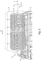
- Figure 1 shows a perspective view of a device 1 according to the invention, mounted on a vehicle 2.
- the device is for delivering traffic cones 3 that have a cone mantle that comprises a flange 4 at its broadest end, and the device comprises a repository for the traffic cones, comprising an outer drum 5 and an inner drum 6, both arranged coaxially about the same length axis 7 with respect to each other and mutually rotatable with respect to each other about said same axis 7.
- the inner drum 6 comprises a helix shaped groove 8 at a side facing the outer drum 5, and the outer drum comprises a blocking 9, for at least partly prohibiting movement of a cone 3 in the direction of the mutual movement 10 of the inner 6 and outer drum 5 and a drive for mutually rotating the inner 6 and outer drum 5.
- the blocking 9 comprises an elevation that extends from the drum wall in a radial direction, and is formed by the outer drum 5 having a polygonal cross section, that is, at least its side facing the inner drum 6.
- the inner drum 6 is arranged fixed with respect to the support, being the vehicle 2, and the outer drum 5 is arranged rotatable with respect to the inner drum 6.
- the device comprises a drive (not shown) configured for rotating the inner and outer drum with an adjustable rotational direction 10 with respect to each other. That means, the device can be used for delivering traffic cones, but also for picking them up at the same side, in the embodiment shown the front side 11 of the vehicle.
- Figure 2 shows a side-view on the device from figure 1 .
- the outer drum 5 is depicted transparent in order to show the inner drum 6, provided with groove 8.
- cones are rotated about the inner drum 6 and since their flanges are positioned in the grooves 8, the cones are moved in the direction 12, toward the front of the vehicle.
- the rear side of the vehicle may be chosen for that purpose as well.
- the groove 8 on the inner drum is in the example described here oriented such that a cone is dropped at a predetermined position 13, from further handling can take place by a placement device.
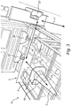
- Figure 3 shows a view on such placement device 14 configured for subsequently dragging (moving in the direction of arrow 15), sliding (moving in the direction of arrow 16) and lifting (moving in the direction of arrow 17) the cone.
- the displacement device comprises three grabbers 19, 20, 21, for performing respectively the drag 15, slide 16 or lift 17 movement.
- the grabbers 19, 20, 21 are operated subsequently and deliver a traffic cone to be placed or to be picked up.
- Figure 4 shows a device according to the invention, comprising a tilting device 22 for tilting a traffic cone prior to placing it on the road surface.
- the placement device is configured for placing the constriction cone right from the vehicle on the road surface, but at operators choice, this may also be in the left side.
- Grabber 20 for the slide movement in the direction of arrow 17 may for that reason be embodied double.
- the displacement device as well as the rest of the device for delivering traffic cones may further be configured for processing traffic cones in opposite order and thus delivering them to the repository from the road surface.
- FIG. 5 shows a vehicle 21 according to another embodiment of the invention, comprising a speed bump placement and/or pick up device 22, as well as a device 23 for delivering traffic cones 24.
Abstract
Description
- The present invention relates to a device for delivering traffic cones. Traffic cones or construction cones or deviation cones are widely used to temporarily mark roads or construction sites or to temporarily block lanes.
- For that purpose, they are usually placed on a road surface, which may be done manually, which is a cumbersome task if the construction covers multiple kilometers, but semi- and full automated systems exist as well. A semi-automated system is described in US Patent
US7431532 . Examples of fully automated systems can be found in Chinese patent applicationsCN107804210 ,CN106320214 andCN105714707 that seem to form the closest prior art. - These systems comprise a repository and a placement device, and fulfil a certain need, be it that the delivery from the repository is a mechanically complex solution in the cases shown, which slows down the placement of the cones, is susceptible to interference and has further disadvantages when it comes to refilling the repository.
- It is therefore a goal of the present invention to provide a system for delivering traffic cones that takes away the disadvantages mentioned, and/or provides a useful alternative to the state of the art.
- The invention thereto proposes a device for delivering traffic cones that have a cone mantle that comprises a flange at its broadest end, comprising a repository for the traffic cones, comprising an outer drum and an inner drum, both arranged coaxially about the same length axis with respect to each other and mutually rotatable with respect to each other about said same axis wherein one of the inner and outer drum comprises a helix shaped groove at a side facing the other of the inner and outer drum, and the other of the inner and outer drum comprises a blocking, for at least partly prohibiting movement of a cone in the direction of the mutual movement of the inner and outer drum, a drive for mutually rotating the inner and outer drum. The length axis may extend in a horizontal or a vertical direction. A horizontal direction may lead to optimal use of the space available on a truck, with a vertical direction, gravity may assist in the movement of the cones.
- The space enclosed by the inner and outer drum serves to store the cones. The cones may be shifted into each other and thus form laying stacks, of which the flanges are arranged in the helix shaped groove. These flanges may have an annular shape and thus the same width all around the cone, or may be of the type that forms a rectangular and in particular square base (with an annular hole from which the cone extends). The space in between the drums can be filled with multiple stacks, that may extend in the axial direction, but it is also thinkable that they have a twist / a helical arrangement as well.
- The repository is operated by mutually rotating the inner and outer drum. The cones are then moved with at least an axial component by the groove which then serves as a screw. The blocking prohibits that the cones rotate along with the drums, and the combination leads to a movement with at least an axial component. Some rotation may be allowed, so the cones may follow a helical path too, but in order to obtain an axial component, they may not be able to rotate to a full extend with the drums.
- In an alternative embodiment, the inner and outer drum do not rotate about the same axis, but one of them is out of the center with respect to the other one. This may allow cones to be taken out of the space between the drums at a specific position, for instance the lowest position.
- Depending on the type of cone to be used, the blocking may comprise an elevation, that extends from the drum wall in a radial direction, like a ridge or a wall. A wall has the advantage that it works for any kind of cone, since it fully blocks the passage, but it may have the disadvantage that it has extra material and thus weight, and that it causes extra friction and is possibly in the way when cones get stuck and need to be released. A ridge may in those cases be a good solution.
- In an embodiment that is in particular suitable for cones with a rectangular or square base, the drum comprising the blocking has a polygonal cross section. Such cross section prohibits a rotation of the stacks of cones along with the drums and provides a number of planes that form a guide for the stacks of cones. The polygonal cross section is at least present at the side facing the other drum.
- Although both configurations are thinkable, in a preferred embodiment, the inner drum is provided with a helix shaped groove facing the outer drum, and the outer drum is provided with the blocking. This configuration has the advantage that less material is required to form the helix, which leads to a lower weight and thus also lower costs.
- In a further embodiment, the inner drum is arranged fixed with respect to a support and the outer drum is arranged rotatable with respect to the inner drum. When the inner drum is the drum provided with the groove, which is to be preferred as described above, this configuration also appears to reduce the risk of crooked cones that may even get stuck.
- In general, it may be preferred that the drum provided with the groove has a determined orientation with respect to the fixed world, since the end of the groove defines the position where the cones are delivered, and a placement device, as described later on in this application, should connect to that position in order to take over the cones, or in case the device is to be filled, to deliver the cones.
- For that latter purpose, in a device according to the invention, the drive may be configured for rotating the inner and outer drum with an adjustable rotational direction with respect to each other. One direction may be used to deliver cones from the repository to a placement device and the other direction may be used to receive cones from the placement device, when the cones are picked up from the road after use. This direction may also be used for initial filling of the repository, although it is also thinkable that the repository is filled at an opposite side seen from where it delivers cones, in which case the rotational direction for delivering and filling is the same.
- The invention also relates to a vehicle, comprising a device for delivering traffic cones as described above. Such vehicle may in general be a truck or a pick-up, that besides the device for delivering traffic cones comprises a placement device, for placing traffic cones on a road surface, which placement device comprises at least a movable grabber, for grabbing a traffic cone delivered by the device for delivering traffic cones, moving said cone and releasing said cone. With these subsequent steps the cone can be moved from the location where the delivery device delivers it to a road surface, and the other way round in case the vehicle is used to pick up the cones from a road after use.
- The placement device may be used for subsequently dragging, sliding and lifting the cone, and may further comprise multiple grabbers, each for performing one of the drag, slide or lift movement. By providing multiple grabbers that each take care for one of the movements, multiple cones can be dealt with at the same time.
- The device according to the invention may further comprise a tilting device for tilting a traffic cone prior to placing it on the road surface, in order to assure that the cone is placed with its base on the road surface. Such placement device may be configured for placing the constriction cone either left or right from the vehicle on the road surface, for instance at an operators choice. The displacement device may further be operated in reverse direction, to provide cones to the repository.
- In a further embodiment the vehicle according to the invention further comprises a speed bump placement and/or pick up device, which enables to provide a complete road deposition in one go.
- The invention will now be elucidated into more detail, with reference to the following figures, that are exemplary and do in no sense limit the scope of the invention as defined by the claims, and wherein:
-
Figure 1 shows a perspective view of a device according to the invention, mounted on a vehicle; -
Figure 2 shows a view of the device fromfigure 1 , with a part taken away; -
Figure 3 shows a placement device, forming part of the present invention; -
Figure 4 shows a tilting device, forming part of the present invention; and -
Figure 5 shows a vehicle with a speed bump placement and/or pick up device. -
Figure 1 shows a perspective view of adevice 1 according to the invention, mounted on avehicle 2. The device is for deliveringtraffic cones 3 that have a cone mantle that comprises aflange 4 at its broadest end, and the device comprises a repository for the traffic cones, comprising anouter drum 5 and aninner drum 6, both arranged coaxially about thesame length axis 7 with respect to each other and mutually rotatable with respect to each other about saidsame axis 7. Theinner drum 6 comprises a helixshaped groove 8 at a side facing theouter drum 5, and the outer drum comprises ablocking 9, for at least partly prohibiting movement of acone 3 in the direction of themutual movement 10 of the inner 6 andouter drum 5 and a drive for mutually rotating the inner 6 andouter drum 5. Theblocking 9 comprises an elevation that extends from the drum wall in a radial direction, and is formed by theouter drum 5 having a polygonal cross section, that is, at least its side facing theinner drum 6. In the embodiment shown, theinner drum 6 is arranged fixed with respect to the support, being thevehicle 2, and theouter drum 5 is arranged rotatable with respect to theinner drum 6. The device comprises a drive (not shown) configured for rotating the inner and outer drum with an adjustablerotational direction 10 with respect to each other. That means, the device can be used for delivering traffic cones, but also for picking them up at the same side, in the embodiment shown thefront side 11 of the vehicle. -
Figure 2 shows a side-view on the device fromfigure 1 . Theouter drum 5 is depicted transparent in order to show theinner drum 6, provided withgroove 8. When theouter drum 5 is rotated in thedirection 10 aboutaxis 7, cones are rotated about theinner drum 6 and since their flanges are positioned in thegrooves 8, the cones are moved in thedirection 12, toward the front of the vehicle. Evidently, the rear side of the vehicle may be chosen for that purpose as well. Thegroove 8 on the inner drum is in the example described here oriented such that a cone is dropped at apredetermined position 13, from further handling can take place by a placement device. -
Figure 3 shows a view onsuch placement device 14 configured for subsequently dragging (moving in the direction of arrow 15), sliding (moving in the direction of arrow 16) and lifting (moving in the direction of arrow 17) the cone. The displacement device comprises threegrabbers drag 15,slide 16 orlift 17 movement. Thegrabbers -
Figure 4 shows a device according to the invention, comprising atilting device 22 for tilting a traffic cone prior to placing it on the road surface. In the example given, the placement device is configured for placing the constriction cone right from the vehicle on the road surface, but at operators choice, this may also be in the left side.Grabber 20 for the slide movement in the direction ofarrow 17 may for that reason be embodied double. The displacement device as well as the rest of the device for delivering traffic cones may further be configured for processing traffic cones in opposite order and thus delivering them to the repository from the road surface. -
Figure 5 shows avehicle 21 according to another embodiment of the invention, comprising a speed bump placement and/or pick updevice 22, as well as adevice 23 for deliveringtraffic cones 24.
Claims (14)
- Device for delivering traffic cones that have a cone mantle that comprises a flange at its broadest end, comprising:- A repository for the traffic cones, comprising:∘ An outer drum; and∘ An inner drum, both arranged coaxially about the same length axis with respect to each other and mutually rotatable with respect to each other about said same axis;- Wherein:∘ one of the inner and outer drum comprises a helix shaped groove at a side facing the other of the inner and outer drum, and the other of the inner and outer drum comprises a blocking, for at least partly prohibiting movement of a cone in the direction of the mutual movement of the inner and outer drum;- a drive for mutually rotating the inner and outer drum.
- Device according to claim 1, wherein the blocking comprises an elevation that extends from the drum wall in a radial direction, like a ridge or a wall.
- Device according to claim 1 or 2, wherein the drum comprising the blocking has a polygonal cross section.
- Device according to any of the preceding claims, wherein the inner drum is provided with a helix shaped groove and the outer drum is provided with the blocking.
- Device according to any of the preceding claims, wherein the inner drum is arranged fixed with respect to a support, and the outer drum is arranged rotatable with respect to the inner drum.
- Device according to any of the preceding claims, wherein the drive is configured for rotating the inner and outer drum with an adjustable rotational direction with respect to each other.
- Vehicle, comprising a device for delivering traffic cones according to any of the preceding claims.
- Vehicle according to claim 7, comprising a placement device, for placing traffic cones on a road surface, which placement device comprises at least a movable grabber, for grabbing a traffic cone delivered by the device for delivering traffic cones, moving said cone and releasing said cone.
- Vehicle according to claim 8, wherein the placement device is configured for subsequently dragging, sliding and lifting the cone.
- Vehicle according to claim 8 or 9, wherein the displacement device comprises multiple grabbers, each for performing one of the drag, slide or lift movement.
- Vehicle according to any of claims 8, 9 or 10, comprising a tilting device for tilting a traffic cone prior to placing it on the road surface.
- Vehicle according to any of claims 8-11, wherein the placement device is configured for placing the constriction cone either left or right from the vehicle on the road surface at operators choice.
- Vehicle according to any of claims 8-12, wherein the displacement device is further configured for processing traffic cones in opposite order and thus delivering them to the repository from the road surface.
- Vehicle according to any of claims 7-13, comprising a speed bump placement and/or pick up device.
Applications Claiming Priority (1)
| Application Number | Priority Date | Filing Date | Title |
|---|---|---|---|
| NL2021455A NL2021455B1 (en) | 2018-08-10 | 2018-08-10 | Device for delivering traffic cones and vehicle comprising such device |
Publications (2)
| Publication Number | Publication Date |
|---|---|
| EP3608475A1 true EP3608475A1 (en) | 2020-02-12 |
| EP3608475B1 EP3608475B1 (en) | 2021-04-21 |
Family
ID=63966012
Family Applications (1)
| Application Number | Title | Priority Date | Filing Date |
|---|---|---|---|
| EP19191065.2A Active EP3608475B1 (en) | 2018-08-10 | 2019-08-09 | Device for delivering traffic cones and vehicle comprising such device |
Country Status (3)
| Country | Link |
|---|---|
| US (1) | US11105054B2 (en) |
| EP (1) | EP3608475B1 (en) |
| NL (1) | NL2021455B1 (en) |
Cited By (1)
| Publication number | Priority date | Publication date | Assignee | Title |
|---|---|---|---|---|
| CN112081028A (en) * | 2020-08-27 | 2020-12-15 | 重庆汇仟知科技有限公司 | Full-automatic vehicle of throwing of highway safety cone |
Families Citing this family (1)
| Publication number | Priority date | Publication date | Assignee | Title |
|---|---|---|---|---|
| CN111719453B (en) * | 2020-07-06 | 2022-04-12 | 广西大学 | Full-automatic traffic cone storage system |
Citations (6)
| Publication number | Priority date | Publication date | Assignee | Title |
|---|---|---|---|---|
| US5525021A (en) * | 1993-09-07 | 1996-06-11 | Baltic Ingenierie | Device for the placement and if desired the collection of traffic cones |
| US20060147264A1 (en) * | 2005-01-06 | 2006-07-06 | Doran John T Jr | Highway marker transfer vehicle |
| US7431532B2 (en) | 2005-06-22 | 2008-10-07 | Scott Lidster | Automated traffic cone handling machine |
| CN105714707A (en) | 2016-02-19 | 2016-06-29 | 河南高远公路养护设备股份有限公司 | Automatic storing and releasing vehicle for traffic cones |
| CN106320214A (en) | 2016-10-18 | 2017-01-11 | 北京泽通科技开发有限公司 | Automatic recovering, distributing and storing vehicle for traffic cones |
| CN107804210A (en) | 2017-09-28 | 2018-03-16 | 中国兵器装备集团上海电控研究所 | A kind of road cone automatic deploying and retracting car based on manipulator |
Family Cites Families (10)
| Publication number | Priority date | Publication date | Assignee | Title |
|---|---|---|---|---|
| US2919830A (en) * | 1956-06-20 | 1960-01-05 | Ralph F Anderson | Multi-stack cup magazine |
| US4166408A (en) * | 1977-09-14 | 1979-09-04 | General Electric Company | Ammunition handling system |
| FR2556378B1 (en) * | 1983-12-13 | 1986-05-23 | Michit Emile | METHOD AND MACHINE FOR COLLECTING, STORING AND MECHANICALLY LAYING CONICAL AND HOLLOW ROAD SIGNALS |
| US5297668A (en) * | 1993-06-29 | 1994-03-29 | Millard Mfg. Corp. | Conveyor for raising and lowering containers including means for manually removing containers therefrom |
| IT1285962B1 (en) * | 1996-06-21 | 1998-06-26 | Gd Spa | METHOD AND DEVICE FOR THE CONVEYANCE, WITH VERTICAL MOVEMENT, OF PACKAGES OF CIGARETTES |
| US6435369B1 (en) * | 1999-05-13 | 2002-08-20 | Farid Poursayadi | Device for placing cones on a roadway surface |
| US20070071584A1 (en) * | 2005-09-23 | 2007-03-29 | Beckstead Gary K | Automated systems, apparatus, and methods for traffic channelizer removal, placement, storage, and transport |
| DE102009008138A1 (en) * | 2009-02-09 | 2010-08-19 | Khs Ag | Transport system for bottles or similar containers |
| FR2942812B1 (en) * | 2009-03-04 | 2012-12-07 | Raymond Soulage | AUTOMATIC DEVICE FOR COLLECTION AND INSTALLATION OF MOTORWAY OR ROAD SIGNALING CONES |
| WO2020033470A1 (en) * | 2018-08-07 | 2020-02-13 | Plastic Safety Systems, Inc. | Vehicle-mountable cargo carrier for portable rumble strips |
-
2018
- 2018-08-10 NL NL2021455A patent/NL2021455B1/en active
-
2019
- 2019-08-09 EP EP19191065.2A patent/EP3608475B1/en active Active
- 2019-08-09 US US16/537,451 patent/US11105054B2/en active Active
Patent Citations (6)
| Publication number | Priority date | Publication date | Assignee | Title |
|---|---|---|---|---|
| US5525021A (en) * | 1993-09-07 | 1996-06-11 | Baltic Ingenierie | Device for the placement and if desired the collection of traffic cones |
| US20060147264A1 (en) * | 2005-01-06 | 2006-07-06 | Doran John T Jr | Highway marker transfer vehicle |
| US7431532B2 (en) | 2005-06-22 | 2008-10-07 | Scott Lidster | Automated traffic cone handling machine |
| CN105714707A (en) | 2016-02-19 | 2016-06-29 | 河南高远公路养护设备股份有限公司 | Automatic storing and releasing vehicle for traffic cones |
| CN106320214A (en) | 2016-10-18 | 2017-01-11 | 北京泽通科技开发有限公司 | Automatic recovering, distributing and storing vehicle for traffic cones |
| CN107804210A (en) | 2017-09-28 | 2018-03-16 | 中国兵器装备集团上海电控研究所 | A kind of road cone automatic deploying and retracting car based on manipulator |
Cited By (2)
| Publication number | Priority date | Publication date | Assignee | Title |
|---|---|---|---|---|
| CN112081028A (en) * | 2020-08-27 | 2020-12-15 | 重庆汇仟知科技有限公司 | Full-automatic vehicle of throwing of highway safety cone |
| CN112081028B (en) * | 2020-08-27 | 2022-05-20 | 重庆汇仟知科技有限公司 | Full-automatic vehicle of puting in of highway safety awl |
Also Published As
| Publication number | Publication date |
|---|---|
| US11105054B2 (en) | 2021-08-31 |
| EP3608475B1 (en) | 2021-04-21 |
| US20200048849A1 (en) | 2020-02-13 |
| NL2021455B1 (en) | 2020-02-20 |
Similar Documents
| Publication | Publication Date | Title |
|---|---|---|
| EP3608475B1 (en) | Device for delivering traffic cones and vehicle comprising such device | |
| EP2825493B1 (en) | Bobbin changing device | |
| EP3504142B1 (en) | A cable drum feeding tool for a vehicle with a lifting device | |
| US4360204A (en) | Golf ball storage and feeder device | |
| CN111212799A (en) | Machine for conveying objects and multi-compartment carousel for use therewith | |
| AU2011223492A1 (en) | A system and method for charging a blast hole | |
| EP3159072A1 (en) | Apparatus for feeding metal bars in a controlled number to a manufacturing machine | |
| EP3241657A1 (en) | Method for mass-production of stiff pre-stressed concrete beams for a floor system with girders and interjoists | |
| JP5527598B2 (en) | Work alignment device | |
| CN107470174A (en) | A kind of spiral detection machine | |
| EP4249410A1 (en) | Machine for orienting and aligning articles supplied in bulk | |
| US7422409B2 (en) | Device for gripping and displacing material, such as roughage | |
| EP2708486B1 (en) | Lifting device for a cable drum | |
| NL1020961C1 (en) | Device and method for manipulating plate-shaped structural elements. | |
| EP0248251A1 (en) | Automated installation to put bricks onto the interior face of a vessel | |
| EP3097031B1 (en) | Component feeder with a lift | |
| WO2010139770A1 (en) | Tool and method for installing blocks of a concrete shield | |
| JP7063166B2 (en) | Bead core transfer device | |
| CN1156109A (en) | Medicine delivering device | |
| CN106005912A (en) | Steel ball feeder | |
| DE102015113274A1 (en) | High-bay warehouse for hanging goods | |
| CN208761518U (en) | A kind of overhead chain conveyer | |
| NL1006769C2 (en) | Silo for bulk material | |
| DE102014108824B4 (en) | Conveying electronic components in bulk by means of a screw conveyor | |
| EP2361500B1 (en) | Adjustment device for adjusting the height position of the hopper for a livestock feeder |
Legal Events
| Date | Code | Title | Description |
|---|---|---|---|
| PUAI | Public reference made under article 153(3) epc to a published international application that has entered the european phase |
Free format text: ORIGINAL CODE: 0009012 |
|
| STAA | Information on the status of an ep patent application or granted ep patent |
Free format text: STATUS: THE APPLICATION HAS BEEN PUBLISHED |
|
| AK | Designated contracting states |
Kind code of ref document: A1 Designated state(s): AL AT BE BG CH CY CZ DE DK EE ES FI FR GB GR HR HU IE IS IT LI LT LU LV MC MK MT NL NO PL PT RO RS SE SI SK SM TR |
|
| AX | Request for extension of the european patent |
Extension state: BA ME |
|
| STAA | Information on the status of an ep patent application or granted ep patent |
Free format text: STATUS: REQUEST FOR EXAMINATION WAS MADE |
|
| 17P | Request for examination filed |
Effective date: 20200812 |
|
| RBV | Designated contracting states (corrected) |
Designated state(s): AL AT BE BG CH CY CZ DE DK EE ES FI FR GB GR HR HU IE IS IT LI LT LU LV MC MK MT NL NO PL PT RO RS SE SI SK SM TR |
|
| GRAP | Despatch of communication of intention to grant a patent |
Free format text: ORIGINAL CODE: EPIDOSNIGR1 |
|
| STAA | Information on the status of an ep patent application or granted ep patent |
Free format text: STATUS: GRANT OF PATENT IS INTENDED |
|
| INTG | Intention to grant announced |
Effective date: 20201118 |
|
| GRAS | Grant fee paid |
Free format text: ORIGINAL CODE: EPIDOSNIGR3 |
|
| GRAA | (expected) grant |
Free format text: ORIGINAL CODE: 0009210 |
|
| STAA | Information on the status of an ep patent application or granted ep patent |
Free format text: STATUS: THE PATENT HAS BEEN GRANTED |
|
| AK | Designated contracting states |
Kind code of ref document: B1 Designated state(s): AL AT BE BG CH CY CZ DE DK EE ES FI FR GB GR HR HU IE IS IT LI LT LU LV MC MK MT NL NO PL PT RO RS SE SI SK SM TR |
|
| REG | Reference to a national code |
Ref country code: GB Ref legal event code: FG4D |
|
| REG | Reference to a national code |
Ref country code: CH Ref legal event code: EP |
|
| REG | Reference to a national code |
Ref country code: DE Ref legal event code: R096 Ref document number: 602019004037 Country of ref document: DE Ref country code: IE Ref legal event code: FG4D |
|
| REG | Reference to a national code |
Ref country code: AT Ref legal event code: REF Ref document number: 1384765 Country of ref document: AT Kind code of ref document: T Effective date: 20210515 |
|
| REG | Reference to a national code |
Ref country code: NL Ref legal event code: FP |
|
| REG | Reference to a national code |
Ref country code: LT Ref legal event code: MG9D |
|
| REG | Reference to a national code |
Ref country code: AT Ref legal event code: MK05 Ref document number: 1384765 Country of ref document: AT Kind code of ref document: T Effective date: 20210421 |
|
| PG25 | Lapsed in a contracting state [announced via postgrant information from national office to epo] |
Ref country code: FI Free format text: LAPSE BECAUSE OF FAILURE TO SUBMIT A TRANSLATION OF THE DESCRIPTION OR TO PAY THE FEE WITHIN THE PRESCRIBED TIME-LIMIT Effective date: 20210421 Ref country code: HR Free format text: LAPSE BECAUSE OF FAILURE TO SUBMIT A TRANSLATION OF THE DESCRIPTION OR TO PAY THE FEE WITHIN THE PRESCRIBED TIME-LIMIT Effective date: 20210421 Ref country code: LT Free format text: LAPSE BECAUSE OF FAILURE TO SUBMIT A TRANSLATION OF THE DESCRIPTION OR TO PAY THE FEE WITHIN THE PRESCRIBED TIME-LIMIT Effective date: 20210421 Ref country code: BG Free format text: LAPSE BECAUSE OF FAILURE TO SUBMIT A TRANSLATION OF THE DESCRIPTION OR TO PAY THE FEE WITHIN THE PRESCRIBED TIME-LIMIT Effective date: 20210721 Ref country code: AT Free format text: LAPSE BECAUSE OF FAILURE TO SUBMIT A TRANSLATION OF THE DESCRIPTION OR TO PAY THE FEE WITHIN THE PRESCRIBED TIME-LIMIT Effective date: 20210421 |
|
| PG25 | Lapsed in a contracting state [announced via postgrant information from national office to epo] |
Ref country code: PT Free format text: LAPSE BECAUSE OF FAILURE TO SUBMIT A TRANSLATION OF THE DESCRIPTION OR TO PAY THE FEE WITHIN THE PRESCRIBED TIME-LIMIT Effective date: 20210823 Ref country code: RS Free format text: LAPSE BECAUSE OF FAILURE TO SUBMIT A TRANSLATION OF THE DESCRIPTION OR TO PAY THE FEE WITHIN THE PRESCRIBED TIME-LIMIT Effective date: 20210421 Ref country code: SE Free format text: LAPSE BECAUSE OF FAILURE TO SUBMIT A TRANSLATION OF THE DESCRIPTION OR TO PAY THE FEE WITHIN THE PRESCRIBED TIME-LIMIT Effective date: 20210421 Ref country code: PL Free format text: LAPSE BECAUSE OF FAILURE TO SUBMIT A TRANSLATION OF THE DESCRIPTION OR TO PAY THE FEE WITHIN THE PRESCRIBED TIME-LIMIT Effective date: 20210421 Ref country code: LV Free format text: LAPSE BECAUSE OF FAILURE TO SUBMIT A TRANSLATION OF THE DESCRIPTION OR TO PAY THE FEE WITHIN THE PRESCRIBED TIME-LIMIT Effective date: 20210421 Ref country code: NO Free format text: LAPSE BECAUSE OF FAILURE TO SUBMIT A TRANSLATION OF THE DESCRIPTION OR TO PAY THE FEE WITHIN THE PRESCRIBED TIME-LIMIT Effective date: 20210721 Ref country code: GR Free format text: LAPSE BECAUSE OF FAILURE TO SUBMIT A TRANSLATION OF THE DESCRIPTION OR TO PAY THE FEE WITHIN THE PRESCRIBED TIME-LIMIT Effective date: 20210722 Ref country code: IS Free format text: LAPSE BECAUSE OF FAILURE TO SUBMIT A TRANSLATION OF THE DESCRIPTION OR TO PAY THE FEE WITHIN THE PRESCRIBED TIME-LIMIT Effective date: 20210821 |
|
| REG | Reference to a national code |
Ref country code: DE Ref legal event code: R097 Ref document number: 602019004037 Country of ref document: DE |
|
| PG25 | Lapsed in a contracting state [announced via postgrant information from national office to epo] |
Ref country code: SK Free format text: LAPSE BECAUSE OF FAILURE TO SUBMIT A TRANSLATION OF THE DESCRIPTION OR TO PAY THE FEE WITHIN THE PRESCRIBED TIME-LIMIT Effective date: 20210421 Ref country code: EE Free format text: LAPSE BECAUSE OF FAILURE TO SUBMIT A TRANSLATION OF THE DESCRIPTION OR TO PAY THE FEE WITHIN THE PRESCRIBED TIME-LIMIT Effective date: 20210421 Ref country code: ES Free format text: LAPSE BECAUSE OF FAILURE TO SUBMIT A TRANSLATION OF THE DESCRIPTION OR TO PAY THE FEE WITHIN THE PRESCRIBED TIME-LIMIT Effective date: 20210421 Ref country code: RO Free format text: LAPSE BECAUSE OF FAILURE TO SUBMIT A TRANSLATION OF THE DESCRIPTION OR TO PAY THE FEE WITHIN THE PRESCRIBED TIME-LIMIT Effective date: 20210421 Ref country code: SM Free format text: LAPSE BECAUSE OF FAILURE TO SUBMIT A TRANSLATION OF THE DESCRIPTION OR TO PAY THE FEE WITHIN THE PRESCRIBED TIME-LIMIT Effective date: 20210421 Ref country code: CZ Free format text: LAPSE BECAUSE OF FAILURE TO SUBMIT A TRANSLATION OF THE DESCRIPTION OR TO PAY THE FEE WITHIN THE PRESCRIBED TIME-LIMIT Effective date: 20210421 Ref country code: DK Free format text: LAPSE BECAUSE OF FAILURE TO SUBMIT A TRANSLATION OF THE DESCRIPTION OR TO PAY THE FEE WITHIN THE PRESCRIBED TIME-LIMIT Effective date: 20210421 |
|
| PLBE | No opposition filed within time limit |
Free format text: ORIGINAL CODE: 0009261 |
|
| STAA | Information on the status of an ep patent application or granted ep patent |
Free format text: STATUS: NO OPPOSITION FILED WITHIN TIME LIMIT |
|
| 26N | No opposition filed |
Effective date: 20220124 |
|
| PG25 | Lapsed in a contracting state [announced via postgrant information from national office to epo] |
Ref country code: MC Free format text: LAPSE BECAUSE OF FAILURE TO SUBMIT A TRANSLATION OF THE DESCRIPTION OR TO PAY THE FEE WITHIN THE PRESCRIBED TIME-LIMIT Effective date: 20210421 |
|
| PG25 | Lapsed in a contracting state [announced via postgrant information from national office to epo] |
Ref country code: IS Free format text: LAPSE BECAUSE OF FAILURE TO SUBMIT A TRANSLATION OF THE DESCRIPTION OR TO PAY THE FEE WITHIN THE PRESCRIBED TIME-LIMIT Effective date: 20210821 Ref country code: LU Free format text: LAPSE BECAUSE OF NON-PAYMENT OF DUE FEES Effective date: 20210809 Ref country code: AL Free format text: LAPSE BECAUSE OF FAILURE TO SUBMIT A TRANSLATION OF THE DESCRIPTION OR TO PAY THE FEE WITHIN THE PRESCRIBED TIME-LIMIT Effective date: 20210421 |
|
| PG25 | Lapsed in a contracting state [announced via postgrant information from national office to epo] |
Ref country code: IT Free format text: LAPSE BECAUSE OF FAILURE TO SUBMIT A TRANSLATION OF THE DESCRIPTION OR TO PAY THE FEE WITHIN THE PRESCRIBED TIME-LIMIT Effective date: 20210421 Ref country code: IE Free format text: LAPSE BECAUSE OF NON-PAYMENT OF DUE FEES Effective date: 20210809 |
|
| REG | Reference to a national code |
Ref country code: CH Ref legal event code: PL |
|
| PG25 | Lapsed in a contracting state [announced via postgrant information from national office to epo] |
Ref country code: LI Free format text: LAPSE BECAUSE OF NON-PAYMENT OF DUE FEES Effective date: 20220831 Ref country code: CH Free format text: LAPSE BECAUSE OF NON-PAYMENT OF DUE FEES Effective date: 20220831 |
|
| PG25 | Lapsed in a contracting state [announced via postgrant information from national office to epo] |
Ref country code: CY Free format text: LAPSE BECAUSE OF FAILURE TO SUBMIT A TRANSLATION OF THE DESCRIPTION OR TO PAY THE FEE WITHIN THE PRESCRIBED TIME-LIMIT Effective date: 20210421 |
|
| PG25 | Lapsed in a contracting state [announced via postgrant information from national office to epo] |
Ref country code: HU Free format text: LAPSE BECAUSE OF FAILURE TO SUBMIT A TRANSLATION OF THE DESCRIPTION OR TO PAY THE FEE WITHIN THE PRESCRIBED TIME-LIMIT; INVALID AB INITIO Effective date: 20190809 |
|
| PGFP | Annual fee paid to national office [announced via postgrant information from national office to epo] |
Ref country code: NL Payment date: 20230826 Year of fee payment: 5 |
|
| PGFP | Annual fee paid to national office [announced via postgrant information from national office to epo] |
Ref country code: GB Payment date: 20230828 Year of fee payment: 5 |
|
| PGFP | Annual fee paid to national office [announced via postgrant information from national office to epo] |
Ref country code: FR Payment date: 20230825 Year of fee payment: 5 Ref country code: DE Payment date: 20230829 Year of fee payment: 5 Ref country code: BE Payment date: 20230828 Year of fee payment: 5 |