EP3607918A1 - System und verfahren zur einführung eines intraluminalen implantats - Google Patents
System und verfahren zur einführung eines intraluminalen implantats Download PDFInfo
- Publication number
- EP3607918A1 EP3607918A1 EP19190496.0A EP19190496A EP3607918A1 EP 3607918 A1 EP3607918 A1 EP 3607918A1 EP 19190496 A EP19190496 A EP 19190496A EP 3607918 A1 EP3607918 A1 EP 3607918A1
- Authority
- EP
- European Patent Office
- Prior art keywords
- pull wire
- gripper
- movement
- channel
- hypotube
- Prior art date
- Legal status (The legal status is an assumption and is not a legal conclusion. Google has not performed a legal analysis and makes no representation as to the accuracy of the status listed.)
- Withdrawn
Links
- 238000000034 method Methods 0.000 title claims abstract description 18
- 239000007943 implant Substances 0.000 title claims description 15
- 230000008878 coupling Effects 0.000 claims description 7
- 238000010168 coupling process Methods 0.000 claims description 7
- 238000005859 coupling reaction Methods 0.000 claims description 7
- 238000002513 implantation Methods 0.000 claims description 7
- 239000000284 extract Substances 0.000 claims description 2
- 230000002401 inhibitory effect Effects 0.000 claims description 2
- 238000010586 diagram Methods 0.000 description 4
- 238000013459 approach Methods 0.000 description 2
- 238000012986 modification Methods 0.000 description 2
- 230000004048 modification Effects 0.000 description 2
- 238000013519 translation Methods 0.000 description 2
- 230000005856 abnormality Effects 0.000 description 1
- 238000013461 design Methods 0.000 description 1
- 238000012377 drug delivery Methods 0.000 description 1
- 230000003073 embolic effect Effects 0.000 description 1
- 230000002496 gastric effect Effects 0.000 description 1
- 230000014759 maintenance of location Effects 0.000 description 1
- 230000002792 vascular Effects 0.000 description 1
Images




Classifications
-
- A—HUMAN NECESSITIES
- A61—MEDICAL OR VETERINARY SCIENCE; HYGIENE
- A61B—DIAGNOSIS; SURGERY; IDENTIFICATION
- A61B17/00—Surgical instruments, devices or methods
- A61B17/12—Surgical instruments, devices or methods for ligaturing or otherwise compressing tubular parts of the body, e.g. blood vessels or umbilical cord
-
- A—HUMAN NECESSITIES
- A61—MEDICAL OR VETERINARY SCIENCE; HYGIENE
- A61F—FILTERS IMPLANTABLE INTO BLOOD VESSELS; PROSTHESES; DEVICES PROVIDING PATENCY TO, OR PREVENTING COLLAPSING OF, TUBULAR STRUCTURES OF THE BODY, e.g. STENTS; ORTHOPAEDIC, NURSING OR CONTRACEPTIVE DEVICES; FOMENTATION; TREATMENT OR PROTECTION OF EYES OR EARS; BANDAGES, DRESSINGS OR ABSORBENT PADS; FIRST-AID KITS
- A61F2/00—Filters implantable into blood vessels; Prostheses, i.e. artificial substitutes or replacements for parts of the body; Appliances for connecting them with the body; Devices providing patency to, or preventing collapsing of, tubular structures of the body, e.g. stents
- A61F2/95—Instruments specially adapted for placement or removal of stents or stent-grafts
- A61F2/962—Instruments specially adapted for placement or removal of stents or stent-grafts having an outer sleeve
-
- A—HUMAN NECESSITIES
- A61—MEDICAL OR VETERINARY SCIENCE; HYGIENE
- A61B—DIAGNOSIS; SURGERY; IDENTIFICATION
- A61B17/00—Surgical instruments, devices or methods
- A61B17/12—Surgical instruments, devices or methods for ligaturing or otherwise compressing tubular parts of the body, e.g. blood vessels or umbilical cord
- A61B17/12022—Occluding by internal devices, e.g. balloons or releasable wires
-
- A—HUMAN NECESSITIES
- A61—MEDICAL OR VETERINARY SCIENCE; HYGIENE
- A61F—FILTERS IMPLANTABLE INTO BLOOD VESSELS; PROSTHESES; DEVICES PROVIDING PATENCY TO, OR PREVENTING COLLAPSING OF, TUBULAR STRUCTURES OF THE BODY, e.g. STENTS; ORTHOPAEDIC, NURSING OR CONTRACEPTIVE DEVICES; FOMENTATION; TREATMENT OR PROTECTION OF EYES OR EARS; BANDAGES, DRESSINGS OR ABSORBENT PADS; FIRST-AID KITS
- A61F2/00—Filters implantable into blood vessels; Prostheses, i.e. artificial substitutes or replacements for parts of the body; Appliances for connecting them with the body; Devices providing patency to, or preventing collapsing of, tubular structures of the body, e.g. stents
- A61F2/95—Instruments specially adapted for placement or removal of stents or stent-grafts
-
- A—HUMAN NECESSITIES
- A61—MEDICAL OR VETERINARY SCIENCE; HYGIENE
- A61B—DIAGNOSIS; SURGERY; IDENTIFICATION
- A61B17/00—Surgical instruments, devices or methods
- A61B17/12—Surgical instruments, devices or methods for ligaturing or otherwise compressing tubular parts of the body, e.g. blood vessels or umbilical cord
- A61B17/12022—Occluding by internal devices, e.g. balloons or releasable wires
- A61B17/12099—Occluding by internal devices, e.g. balloons or releasable wires characterised by the location of the occluder
- A61B17/12109—Occluding by internal devices, e.g. balloons or releasable wires characterised by the location of the occluder in a blood vessel
-
- A—HUMAN NECESSITIES
- A61—MEDICAL OR VETERINARY SCIENCE; HYGIENE
- A61F—FILTERS IMPLANTABLE INTO BLOOD VESSELS; PROSTHESES; DEVICES PROVIDING PATENCY TO, OR PREVENTING COLLAPSING OF, TUBULAR STRUCTURES OF THE BODY, e.g. STENTS; ORTHOPAEDIC, NURSING OR CONTRACEPTIVE DEVICES; FOMENTATION; TREATMENT OR PROTECTION OF EYES OR EARS; BANDAGES, DRESSINGS OR ABSORBENT PADS; FIRST-AID KITS
- A61F2/00—Filters implantable into blood vessels; Prostheses, i.e. artificial substitutes or replacements for parts of the body; Appliances for connecting them with the body; Devices providing patency to, or preventing collapsing of, tubular structures of the body, e.g. stents
- A61F2/95—Instruments specially adapted for placement or removal of stents or stent-grafts
- A61F2/9517—Instruments specially adapted for placement or removal of stents or stent-grafts handle assemblies therefor
-
- A—HUMAN NECESSITIES
- A61—MEDICAL OR VETERINARY SCIENCE; HYGIENE
- A61F—FILTERS IMPLANTABLE INTO BLOOD VESSELS; PROSTHESES; DEVICES PROVIDING PATENCY TO, OR PREVENTING COLLAPSING OF, TUBULAR STRUCTURES OF THE BODY, e.g. STENTS; ORTHOPAEDIC, NURSING OR CONTRACEPTIVE DEVICES; FOMENTATION; TREATMENT OR PROTECTION OF EYES OR EARS; BANDAGES, DRESSINGS OR ABSORBENT PADS; FIRST-AID KITS
- A61F2/00—Filters implantable into blood vessels; Prostheses, i.e. artificial substitutes or replacements for parts of the body; Appliances for connecting them with the body; Devices providing patency to, or preventing collapsing of, tubular structures of the body, e.g. stents
- A61F2/95—Instruments specially adapted for placement or removal of stents or stent-grafts
- A61F2/9522—Means for mounting a stent or stent-graft onto or into a placement instrument
-
- A—HUMAN NECESSITIES
- A61—MEDICAL OR VETERINARY SCIENCE; HYGIENE
- A61F—FILTERS IMPLANTABLE INTO BLOOD VESSELS; PROSTHESES; DEVICES PROVIDING PATENCY TO, OR PREVENTING COLLAPSING OF, TUBULAR STRUCTURES OF THE BODY, e.g. STENTS; ORTHOPAEDIC, NURSING OR CONTRACEPTIVE DEVICES; FOMENTATION; TREATMENT OR PROTECTION OF EYES OR EARS; BANDAGES, DRESSINGS OR ABSORBENT PADS; FIRST-AID KITS
- A61F2/00—Filters implantable into blood vessels; Prostheses, i.e. artificial substitutes or replacements for parts of the body; Appliances for connecting them with the body; Devices providing patency to, or preventing collapsing of, tubular structures of the body, e.g. stents
- A61F2/95—Instruments specially adapted for placement or removal of stents or stent-grafts
- A61F2/962—Instruments specially adapted for placement or removal of stents or stent-grafts having an outer sleeve
- A61F2/966—Instruments specially adapted for placement or removal of stents or stent-grafts having an outer sleeve with relative longitudinal movement between outer sleeve and prosthesis, e.g. using a push rod
-
- A—HUMAN NECESSITIES
- A61—MEDICAL OR VETERINARY SCIENCE; HYGIENE
- A61M—DEVICES FOR INTRODUCING MEDIA INTO, OR ONTO, THE BODY; DEVICES FOR TRANSDUCING BODY MEDIA OR FOR TAKING MEDIA FROM THE BODY; DEVICES FOR PRODUCING OR ENDING SLEEP OR STUPOR
- A61M25/00—Catheters; Hollow probes
- A61M25/01—Introducing, guiding, advancing, emplacing or holding catheters
- A61M25/0105—Steering means as part of the catheter or advancing means; Markers for positioning
- A61M25/0133—Tip steering devices
- A61M25/0147—Tip steering devices with movable mechanical means, e.g. pull wires
-
- A—HUMAN NECESSITIES
- A61—MEDICAL OR VETERINARY SCIENCE; HYGIENE
- A61M—DEVICES FOR INTRODUCING MEDIA INTO, OR ONTO, THE BODY; DEVICES FOR TRANSDUCING BODY MEDIA OR FOR TAKING MEDIA FROM THE BODY; DEVICES FOR PRODUCING OR ENDING SLEEP OR STUPOR
- A61M25/00—Catheters; Hollow probes
- A61M25/01—Introducing, guiding, advancing, emplacing or holding catheters
- A61M25/02—Holding devices, e.g. on the body
-
- A—HUMAN NECESSITIES
- A61—MEDICAL OR VETERINARY SCIENCE; HYGIENE
- A61B—DIAGNOSIS; SURGERY; IDENTIFICATION
- A61B17/00—Surgical instruments, devices or methods
- A61B17/12—Surgical instruments, devices or methods for ligaturing or otherwise compressing tubular parts of the body, e.g. blood vessels or umbilical cord
- A61B17/12022—Occluding by internal devices, e.g. balloons or releasable wires
- A61B2017/1205—Introduction devices
-
- A—HUMAN NECESSITIES
- A61—MEDICAL OR VETERINARY SCIENCE; HYGIENE
- A61B—DIAGNOSIS; SURGERY; IDENTIFICATION
- A61B17/00—Surgical instruments, devices or methods
- A61B17/12—Surgical instruments, devices or methods for ligaturing or otherwise compressing tubular parts of the body, e.g. blood vessels or umbilical cord
- A61B17/12022—Occluding by internal devices, e.g. balloons or releasable wires
- A61B2017/1205—Introduction devices
- A61B2017/12054—Details concerning the detachment of the occluding device from the introduction device
-
- A—HUMAN NECESSITIES
- A61—MEDICAL OR VETERINARY SCIENCE; HYGIENE
- A61F—FILTERS IMPLANTABLE INTO BLOOD VESSELS; PROSTHESES; DEVICES PROVIDING PATENCY TO, OR PREVENTING COLLAPSING OF, TUBULAR STRUCTURES OF THE BODY, e.g. STENTS; ORTHOPAEDIC, NURSING OR CONTRACEPTIVE DEVICES; FOMENTATION; TREATMENT OR PROTECTION OF EYES OR EARS; BANDAGES, DRESSINGS OR ABSORBENT PADS; FIRST-AID KITS
- A61F2/00—Filters implantable into blood vessels; Prostheses, i.e. artificial substitutes or replacements for parts of the body; Appliances for connecting them with the body; Devices providing patency to, or preventing collapsing of, tubular structures of the body, e.g. stents
- A61F2/82—Devices providing patency to, or preventing collapsing of, tubular structures of the body, e.g. stents
-
- A—HUMAN NECESSITIES
- A61—MEDICAL OR VETERINARY SCIENCE; HYGIENE
- A61F—FILTERS IMPLANTABLE INTO BLOOD VESSELS; PROSTHESES; DEVICES PROVIDING PATENCY TO, OR PREVENTING COLLAPSING OF, TUBULAR STRUCTURES OF THE BODY, e.g. STENTS; ORTHOPAEDIC, NURSING OR CONTRACEPTIVE DEVICES; FOMENTATION; TREATMENT OR PROTECTION OF EYES OR EARS; BANDAGES, DRESSINGS OR ABSORBENT PADS; FIRST-AID KITS
- A61F2/00—Filters implantable into blood vessels; Prostheses, i.e. artificial substitutes or replacements for parts of the body; Appliances for connecting them with the body; Devices providing patency to, or preventing collapsing of, tubular structures of the body, e.g. stents
- A61F2/95—Instruments specially adapted for placement or removal of stents or stent-grafts
- A61F2002/9505—Instruments specially adapted for placement or removal of stents or stent-grafts having retaining means other than an outer sleeve, e.g. male-female connector between stent and instrument
- A61F2002/9511—Instruments specially adapted for placement or removal of stents or stent-grafts having retaining means other than an outer sleeve, e.g. male-female connector between stent and instrument the retaining means being filaments or wires
-
- A—HUMAN NECESSITIES
- A61—MEDICAL OR VETERINARY SCIENCE; HYGIENE
- A61F—FILTERS IMPLANTABLE INTO BLOOD VESSELS; PROSTHESES; DEVICES PROVIDING PATENCY TO, OR PREVENTING COLLAPSING OF, TUBULAR STRUCTURES OF THE BODY, e.g. STENTS; ORTHOPAEDIC, NURSING OR CONTRACEPTIVE DEVICES; FOMENTATION; TREATMENT OR PROTECTION OF EYES OR EARS; BANDAGES, DRESSINGS OR ABSORBENT PADS; FIRST-AID KITS
- A61F2/00—Filters implantable into blood vessels; Prostheses, i.e. artificial substitutes or replacements for parts of the body; Appliances for connecting them with the body; Devices providing patency to, or preventing collapsing of, tubular structures of the body, e.g. stents
- A61F2/95—Instruments specially adapted for placement or removal of stents or stent-grafts
- A61F2/962—Instruments specially adapted for placement or removal of stents or stent-grafts having an outer sleeve
- A61F2/966—Instruments specially adapted for placement or removal of stents or stent-grafts having an outer sleeve with relative longitudinal movement between outer sleeve and prosthesis, e.g. using a push rod
- A61F2002/9665—Instruments specially adapted for placement or removal of stents or stent-grafts having an outer sleeve with relative longitudinal movement between outer sleeve and prosthesis, e.g. using a push rod with additional retaining means
-
- A—HUMAN NECESSITIES
- A61—MEDICAL OR VETERINARY SCIENCE; HYGIENE
- A61M—DEVICES FOR INTRODUCING MEDIA INTO, OR ONTO, THE BODY; DEVICES FOR TRANSDUCING BODY MEDIA OR FOR TAKING MEDIA FROM THE BODY; DEVICES FOR PRODUCING OR ENDING SLEEP OR STUPOR
- A61M25/00—Catheters; Hollow probes
- A61M25/01—Introducing, guiding, advancing, emplacing or holding catheters
- A61M25/02—Holding devices, e.g. on the body
- A61M2025/0293—Catheter, guide wire or the like with means for holding, centering, anchoring or frictionally engaging the device within an artificial lumen, e.g. tube
Definitions
- the present invention generally relates to medical devices, and more particularly, to deploying intraluminal implants.
- Implant devices are well known in the field. Many are deployed mechanically, via systems that combine one or more catheters and wires for delivery. Examples of implants that may be delivered mechanically include embolic elements, stents, grafts, drug delivery implants, etc. Some obstetric and gastrointestinal implants may also be implanted via similar systems that combine one or more catheters and wires. Devices that may be released or deployed by mechanical means vary greatly in design but can employ a similar delivery catheter and wire system. Many such catheter-based delivery systems include a wire for retention of the implant in the catheter until the time for release of the device. These systems are then actuated by retracting or pulling the wire relative to the catheter. Such a wire is referred to herein as a "pull wire".
- Examples in general can include an implantation device having a pull wire extending from a proximal end of a hypotube, and the pull wire can have an engagement bump or extending portion near a proximal end of the pull wire.
- Examples in general can additionally or alternatively include a device for retracting the pull wire from the hypotube.
- the retracting device can have a channel or groove in which the pull wire and engagement bump can be positioned and movable grippers or retractors that can be moved to engage the engagement bump of the pull wire.
- the grippers can pull the pull wire proximally through the channel, or if the grippers are subsequently moved distally, the grippers can disengage the engagement bump without disturbing the position of the pull wire or causing the pull wire to move distally.
- a system for deploying an implant can include a hypotube, a pull wire, an engagement bump positioned on the pull wire, a groove sized to slidably receive the engagement bump, and a movable gripper.
- the pull wire can be positioned within a lumen of the hypotube extending proximally out of the hypotube lumen, and the engagement bump can be positioned near a proximal end of the pull wire.
- the gripper can be movable in a proximal direction and a distal direction such that the gripper can engage the engagement bump upon movement in the proximal direction and disengage the engagement bump upon movement in the distal direction.
- a movement of the gripper in the proximal direction can solely engage the engagement bump of the pull wire and no other surface of the pull wire.
- the system can further include a space maintained between the gripper and a circumference of the pull wire.
- the engagement bump can slide through a first length of the groove in the proximal direction upon a first movement of the gripper in the proximal direction, the engagement bump can remain stationary in relation to the groove upon a second movement of the gripper in the distal direction, and the engagement bump can slide through a second length of the groove in the proximal direction upon a third movement of the gripper in the proximal direction.
- the system can further include a track through which the gripper can move.
- the track can have a parallel segment positioned parallel to the channel and an extending segment positioned distal the parallel segment and extending away from the channel in at least a lateral direction.
- the gripper can extend the pull wire proximally from the proximal end of the hypotube upon a movement of the gripper in the proximal direction, and the pull wire can remain stationary in relation to the hypotube upon a movement of the gripper in the distal direction.
- the gripper can also be movable in a lateral direction, and a movement of the gripper in the proximal direction can result in a first lateral movement approaching the pull wire, and a movement of the gripper in the distal direction can result in a second lateral movement retreating from the pull wire.
- the system can further include a spring applying a spring force to the gripper in the distal direction.
- the groove can further include a distal end engaging the proximal end of the hypotube and preventing proximal movement of the hypotube in relation to the groove.
- the groove can be sized to inhibit a lateral movement of the engagement bump.
- the system can further include a first and second gripper, each movable in the distal direction and the proximal direction, each engaging the engagement bump upon movement in the proximal direction and disengaging the engagement bump upon movement in the distal direction.
- the first and second gripper can be joined for simultaneous movement in the proximal direction and the distal direction.
- An example device for retracting a pull wire from a hypotube can include a receptacle having a channel and a distal surface and a retractor coupled to the receptacle having an engagement surface.
- the channel of the receptacle can slidably receive a pull wire, and the distal surface of the receptacle can engage a proximal end of a hypotube.
- the retractor can be movable in a proximal direction and a distal direction parallel to the channel, and the engagement surface can be positioned approximate the channel to engage an extending portion of the pull wire.
- a proximal movement of the retractor can extract the pull wire from the proximal end of the hypotube, thereby extending the pull wire into the channel.
- a subsequent distal movement of the retractor can disengage the extending portion of the pull wire such that pull wire remains stationary in relation to the hypotube.
- the device can further include a track having a parallel segment positioned parallel to the channel.
- the retractor can be coupled to the track such that the parallel segment inhibits lateral movement of the retractor.
- the track can further comprise an extending segment positioned distal the parallel segment that extends away from the channel, and the retractor can be movable in at least a lateral direction when moved along the extending segment of the track.
- the device can further include a spring applying spring force to the retractor in the distal direction.
- the device can further include a first retractor movable within a first track and second retractor movable within a second track.
- the first and second tracks can be shaped as mirror images of each other about an axis defined by the length of the channel, and the first and second retractors can be coupled for simultaneous movement.
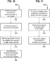
- An example method of manipulating an implant delivery system can include the steps of providing an implantation device having a pull wire and a hypotube, positioning an engagement bump on the pull wire near a proximal end of the pull wire, providing a retracting device having a channel and a gripper, positioning the pull wire within the channel, engaging a proximal end of the hypotube with a distal surface of the retracting device, moving the gripper to engage the engagement bump, pulling the gripper and the engaged engagement bump proximally through the channel thereby retracting the pull wire proximally from the proximal end of the hypotube, moving the gripper distally to disengage the engagement bump, and maintaining a stationary position of the pull wire in relation to the channel in response to the moving of the gripper distally.
- the method can further include the steps of providing a parallel track segment positioned parallel to the channel, coupling the gripper to the parallel track segment, moving the gripper through the parallel track segment parallel to the channel, and inhibiting lateral movement of the gripper by the coupling of the parallel track segment.
- the retracting device can have two grippers: the aforementioned gripper and second gripper, and the method can further include the steps of positioning the grippers on opposite sides of the channel and coupling the grippers to each other for simultaneous movement.
- An implant delivery system can include a pull wire extending from a catheter or hypotube having an engagement bump or extending portion at the proximal end of the pull wire.
- the pull wire can be positioned within a groove or channel of a retracting device and can be controllably slid through the groove while the hypotube is prevented from moving through the groove.
- the retracting device can include tracks positioned on opposite sides of the groove that together make a Y-shape, and grippers or retractors can be guided by the tracks along the pull wire groove.
- the grippers In their initial position, the grippers can be positioned on the wide, distal end of the Y-track.
- the grippers can be translated proximally through the Y-track, moving closer to the pull wire until the grippers contact the engagement bump, but not the pull wire.
- the grippers can be further translated proximally through a parallel portion of the Y-track, pulling the engagement bump (and therefore the pull wire) proximally in the process.
- the retracting device can include springs attached to the grippers that can provide a spring force pushing the grippers distally, and the grippers can be joined together for simultaneous translation by a slider.
- the grippers can move distally to their initial position on the wide, distal end of the track. Movement of the grippers distally can disengage the engagement bump without disturbing the pull wire. Even in a scenario wherein the grippers are prematurely released, the grippers can move distally without causing distal translation of the pull wire.
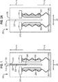
- FIG. 1 An example system 100 for deploying an implant is illustrated in FIG. 1 .
- the system 100 can include an implantation device having a hypotube 310 and a pull wire 320 and a retractor device having a channel or groove 220 and one or more grippers or retractors 240.
- the pull wire 320 can extend proximally from a lumen 316 of the hypotube 310.
- the pull wire 320 can be positioned in the channel 220, and the hypotube 310 can be positioned to have a proximal surface 312 abutting the retractor device, preventing the hypotube 310 from travelling proximally through the channel 220.
- the pull wire 320 can have an engagement bump 328 positioned on or near the proximal end 324 of the pull wire 320, and the engagement bump 328 can be sized to slide through the channel 220.
- FIG. 1 depicts grippers 240 positioned in a starting position, pushed in a distal direction 14 by springs 250. As shown, the grippers 240 can be positioned within tracks 260 and can be pulled in a proximal direction 12 through the tracks 260 with the springs 250 providing an opposing spring force.
- the tracks 260 can form a Y-shape such that when the grippers 240 are pulled proximally, the grippers 240 approach the pull wire 320 and engage the engagement bump 328 of the pull wire 320.
- the grippers 240 can then be pulled proximally parallel to the channel 220, maintaining a space between the grippers 240 and the pull wire 320. Once released, the grippers 240 can disengage the engagement bump 328 and return to the starting position without disturbing the positioning of the pull wire 320.
- FIG. 2A depicts an exemplary retractor device 200.
- the retractor device can have a receptacle 210 for receiving a pull wire 320 of an implantation device.
- FIG. 2B is a close-up drawing of a portion of the exemplary device of FIG. 2A depicting a track 260 and a channel 220.
- the track 260 can have a parallel segment 262 travelling substantially parallel to the channel 220 and an extending segment 264 that extends in at least a lateral direction 20 away from the channel 220. As shown the extending section can also extend distally to form half of a Y-shape.
- the device of FIG. 2A can have two tracks 260 positioned opposite the channel 220, mirrored about a central axis 232 to form two halves of the Y-shape.
- FIG. 3 is a close-up drawing of a portion of an exemplary system.
- a pull wire 320 can extend from a hypotube lumen 316 and be positioned within a channel 220.
- the channel 220 can have a width 222 sized to slidably receive an engagement bump 328 at a proximal end 324 of the pull wire 320 while simultaneously stopping the hypotube 310 from travelling proximally.
- the hypotube 310 can have a circumference 318 that is sized larger than the channel 220, and the retraction device can have a distal surface 230 near the distal end 224 of the channel 220 so that when the pull wire 320 is positioned in the channel 220, a proximal end 312 of the hypotube 310 can abut the distal surface 230 of the retraction device, thereby preventing proximal movement of the hypotube 310 in relation to the channel 220.
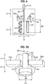
- FIG. 4 is a drawing illustrating a pair of grippers 240a, 240b positioned to engage an engagement bump 328 of a pull wire 320.
- a first and second gripper can be moved along a first and second track 260a,260b such that the tracks form a Y-shape.
- Each track can have an extending segment 264 that extends away from the channel 220 and a parallel segment 262 that extends parallel to the channel 220.
- the grippers 240a, 240b are shown positioned at the intersection of the extending segments 264 and the parallel segments 262. In this position the grippers 240a,240b can engage the engagement bump 328, and further proximal movement of the grippers 240a,240b can cause the pull wire 320 to travel proximally through the channel 220.
- FIG. 5A is a close-up drawing depicting a pair of grippers 240a, 240b positioned near an engagement bump 328 on a pull wire 320.
- Each gripper can have an engagement surface 242 that can engage the engagement bump 328 when the grippers 240a,240b are pulled in the proximal direction 12.
- the pull wire 320 can have a circumference 326 that is narrower than the engagement bump 328 and grippers 240a,240b can approach the pull wire 320 to engage the engagement bump 328 without making contact to the pull wire 320.
- the channel 220 can have a width 222, and the circumference 326 of the pull wire 320 can be sized such that the grippers 240a,240b can extend into the channel 220 to engage the engagement bump 328 without making contact to the pull wire 320.
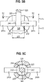
- FIG. 5B is a close-up drawing depicting the pair of grippers 240a,240b engaging the engagement bump 328.
- the grippers 240a,240b have been moved in the proximal direction 12 in relation to FIG. 5A .
- a space 244 is maintained between the grippers 240a,240b and the pull wire circumference 326 such that the grippers 240a,240b solely engage the engagement bump 328 and do not otherwise engage the pull wire 320.
- FIG. 5C is a cross-sectional view of the system depicted in FIG. 5B .
- the pull wire 320 is shown centrally located with the engagement bump 328 extending circumferentially from the pull wire 320, and the channel 220 is shown partially surrounding the engagement bump 328.
- the grippers 240a,240b are shown overlapping the engagement bump 328 such that each gripper has an engagement surface 242 defined by the overlap of the gripper with the engagement bump 328.
- a gap 244 is shown positioned between the grippers 240a,240b and the pull wire 320 such that the grippers 240a,240b do not contact the pull wire 320.
- FIG. 6 is a drawing depicting a pull wire 320 fully retracted.
- a first and second gripper can be moved proximally through a first and second track 260a,260b to retract the pull wire 320 from a hypotube 310.
- FIG. 6 shows the grippers 240a,240b each positioned a proximal end of their respective tracks 260a,260b.
- FIG. 7 is a drawing depicting a pair of grippers 240a,240b returned to their original position following the retraction of the pull wire 320.
- the springs 250 can move each gripper through each track 260a,260b to their original position while the pull wire 320 remains fully retracted.
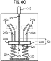
- FIGs. 8A to 8C are drawings depicting a series of movements of the grippers 240a,240b.
- FIG. 8A depicts a first movement of the grippers 240a,240b in the proximal direction 12 along a parallel segment 262 of each respective track 260a,260b.
- the grippers 240a,240b can be engaged with the engagement bump 328 causing the pull wire 320 to slide through a first length 226 of the channel 220.
- FIG. 8B depicts a second movement of the grippers 240a,240b in the distal direction 14. Distal movement of the grippers 240a,240b can disengage the engagement bump 328, and the pull wire 320 can remain in the partially retracted position as depicted in FIG. 8A .
- FIG. 8A depicts a first movement of the grippers 240a,240b in the proximal direction 12 along a parallel segment 262 of each respective track 260a,260b.
- the grippers 240a,240b can
- FIG. 8C depicts a third movement of the grippers 240a,240b in the proximal direction 12. If the grippers 240a,240b are moved further proximally than as shown in FIG. 8A , the grippers 240a,240b can engage the engagement bump 328 and move the pull wire 320 proximally through a second length 228 of the wire.
- FIG. 9 is a flow diagram 700 outlining method steps that can be performed during implant delivery.
- an implantation device having a pull wire and a hypotube can be provided.
- an engagement bump can be positioned on the pull wire approximate a proximal end of the pull wire.
- a retracting device having a channel and a gripper can be provided.
- a pull wire can be positioned within the channel.
- a proximal end of the hypotube can engage a distal surface of the retracting device.
- the gripper can be moved to engage the engagement bump.
- step 770 the gripper and the engaged engagement bump can be pulled proximally through the channel thereby retracting the pull wire proximally from the proximal end of the hypotube.
- step 780 the gripper can be moved distally to disengage the engagement bump.
- step 790 the pull wire can remain in a stationary position in relation to the channel as the gripper is moved distally.
- FIG. 10 is a flow diagram 800 outlining method steps that can be performed in addition to or in place of method steps outlined in FIG. 9 .
- a parallel track segment can be positioned parallel to the channel.
- the gripper can be coupled to the parallel track segment.
- the gripper can be moved parallel to the channel through the parallel track segment.
- the coupling of the gripper to the parallel track segment can inhibit lateral movement of the gripper.
- FIG. 11 is a flow diagram 900 outlining method steps that can be performed in addition to or in place of method steps outlined in FIGs. 9 and 10 .
- a retracting device comprising a channel and a pair of grippers can be provided.
- the grippers can be positioned opposite each other on opposite sides of the channel.
- the grippers can be coupled to each other for simultaneous movement.
- the invention contemplates many variations and modifications of the implantation deployment system, including alternative structures for the engagement bump such as a ball or hook or other shape providing similar functionality, alternative means for guiding the grippers in relation to the channel, alternative means for receiving and preventing proximal movement of the hypotube, alternative means of allowing the engagement bump to pass proximally through the gripper space when placing in the groove, etc.
- alternative structures for the engagement bump such as a ball or hook or other shape providing similar functionality
- alternative means for guiding the grippers in relation to the channel alternative means for receiving and preventing proximal movement of the hypotube
- alternative means of allowing the engagement bump to pass proximally through the gripper space when placing in the groove etc.
Landscapes
- Health & Medical Sciences (AREA)
- Engineering & Computer Science (AREA)
- Biomedical Technology (AREA)
- Life Sciences & Earth Sciences (AREA)
- Veterinary Medicine (AREA)
- Heart & Thoracic Surgery (AREA)
- Animal Behavior & Ethology (AREA)
- General Health & Medical Sciences (AREA)
- Public Health (AREA)
- Vascular Medicine (AREA)
- Transplantation (AREA)
- Oral & Maxillofacial Surgery (AREA)
- Cardiology (AREA)
- Surgery (AREA)
- Nuclear Medicine, Radiotherapy & Molecular Imaging (AREA)
- Reproductive Health (AREA)
- Medical Informatics (AREA)
- Molecular Biology (AREA)
- Biophysics (AREA)
- Pulmonology (AREA)
- Anesthesiology (AREA)
- Hematology (AREA)
- Mechanical Engineering (AREA)
- Surgical Instruments (AREA)
- Media Introduction/Drainage Providing Device (AREA)
- Prostheses (AREA)
Applications Claiming Priority (1)
| Application Number | Priority Date | Filing Date | Title |
|---|---|---|---|
| US16/058,932 US10813780B2 (en) | 2018-08-08 | 2018-08-08 | Intraluminal implant delivery system and method |
Publications (1)
| Publication Number | Publication Date |
|---|---|
| EP3607918A1 true EP3607918A1 (de) | 2020-02-12 |
Family
ID=67658518
Family Applications (1)
| Application Number | Title | Priority Date | Filing Date |
|---|---|---|---|
| EP19190496.0A Withdrawn EP3607918A1 (de) | 2018-08-08 | 2019-08-07 | System und verfahren zur einführung eines intraluminalen implantats |
Country Status (12)
| Country | Link |
|---|---|
| US (2) | US10813780B2 (de) |
| EP (1) | EP3607918A1 (de) |
| JP (1) | JP7438688B2 (de) |
| KR (1) | KR20200017368A (de) |
| CN (1) | CN110811731A (de) |
| AU (1) | AU2019213324A1 (de) |
| BR (1) | BR102019016382A2 (de) |
| CA (1) | CA3051302A1 (de) |
| CO (1) | CO2019008622A1 (de) |
| IL (1) | IL268535A (de) |
| RU (1) | RU2019125011A (de) |
| TW (1) | TWI822829B (de) |
Citations (3)
| Publication number | Priority date | Publication date | Assignee | Title |
|---|---|---|---|---|
| WO1998011846A1 (en) * | 1996-09-18 | 1998-03-26 | Micro Therapeutics, Inc. | Intracranial stent and method of use |
| US20120029607A1 (en) * | 2010-07-30 | 2012-02-02 | Mchugo Vincent | Controlled release and recapture prosthetic deployment device |
| US20170367857A1 (en) * | 2009-09-22 | 2017-12-28 | Penumbra Inc. | Manual actuation system for deployment of implant |
Family Cites Families (129)
| Publication number | Priority date | Publication date | Assignee | Title |
|---|---|---|---|---|
| US5814062A (en) | 1994-12-22 | 1998-09-29 | Target Therapeutics, Inc. | Implant delivery assembly with expandable coupling/decoupling mechanism |
| US6102932A (en) | 1998-12-15 | 2000-08-15 | Micrus Corporation | Intravascular device push wire delivery system |
| US6758830B1 (en) * | 1999-05-11 | 2004-07-06 | Atrionix, Inc. | Catheter positioning system |
| US6613075B1 (en) * | 1999-10-27 | 2003-09-02 | Cordis Corporation | Rapid exchange self-expanding stent delivery catheter system |
| US6391037B1 (en) | 2000-03-02 | 2002-05-21 | Prodesco, Inc. | Bag for use in the intravascular treatment of saccular aneurysms |
| US8252040B2 (en) | 2001-07-20 | 2012-08-28 | Microvention, Inc. | Aneurysm treatment device and method of use |
| US8715312B2 (en) | 2001-07-20 | 2014-05-06 | Microvention, Inc. | Aneurysm treatment device and method of use |
| US6773448B2 (en) | 2002-03-08 | 2004-08-10 | Ev3 Inc. | Distal protection devices having controllable wire motion |
| EP1608299B1 (de) | 2003-03-26 | 2010-05-12 | Cardiomind, Inc. | Implantatablage-katheter mit elektrolytisch abbaubaren verbindungen |
| US7371228B2 (en) | 2003-09-19 | 2008-05-13 | Medtronic Vascular, Inc. | Delivery of therapeutics to treat aneurysms |
| US7419498B2 (en) | 2003-10-21 | 2008-09-02 | Nmt Medical, Inc. | Quick release knot attachment system |
| US7361180B2 (en) * | 2004-05-07 | 2008-04-22 | Usgi Medical, Inc. | Apparatus for manipulating and securing tissue |
| US20050209673A1 (en) * | 2004-03-04 | 2005-09-22 | Y Med Inc. | Bifurcation stent delivery devices |
| US9308382B2 (en) | 2004-06-10 | 2016-04-12 | Medtronic Urinary Solutions, Inc. | Implantable pulse generator systems and methods for providing functional and/or therapeutic stimulation of muscles and/or nerves and/or central nervous system tissue |
| US9655633B2 (en) | 2004-09-10 | 2017-05-23 | Penumbra, Inc. | System and method for treating ischemic stroke |
| CA2581272A1 (en) | 2004-09-22 | 2006-05-18 | Lee R. Guterman | Cranial aneurysm treatment arrangement |
| US20060089637A1 (en) | 2004-10-14 | 2006-04-27 | Werneth Randell L | Ablation catheter |
| US8562672B2 (en) | 2004-11-19 | 2013-10-22 | Medtronic, Inc. | Apparatus for treatment of cardiac valves and method of its manufacture |
| US9636115B2 (en) | 2005-06-14 | 2017-05-02 | Stryker Corporation | Vaso-occlusive delivery device with kink resistant, flexible distal end |
| CN101309651B (zh) | 2005-06-20 | 2011-12-07 | 麦德托尼克消融前沿有限公司 | 消融导管 |
| CA2630021C (en) | 2005-11-17 | 2013-08-13 | Microvention, Inc. | Three-dimensional complex coil |
| US7942894B2 (en) | 2006-01-31 | 2011-05-17 | Codman & Shurtleff, Inc. | Embolic device delivery system |
| US9757260B2 (en) | 2006-03-30 | 2017-09-12 | Medtronic Vascular, Inc. | Prosthesis with guide lumen |
| US9615832B2 (en) | 2006-04-07 | 2017-04-11 | Penumbra, Inc. | Aneurysm occlusion system and method |
| JP2010500917A (ja) | 2006-06-15 | 2010-01-14 | マイクロベンション, インコーポレイテッド | 膨張性ポリマーで構成される塞栓形成デバイス |
| US20080281350A1 (en) | 2006-12-13 | 2008-11-13 | Biomerix Corporation | Aneurysm Occlusion Devices |
| AU2008345590B2 (en) | 2007-12-21 | 2014-10-30 | Microvention, Inc. | Hydrogel filaments for biomedical uses |
| US8974518B2 (en) | 2008-03-25 | 2015-03-10 | Medtronic Vascular, Inc. | Eversible branch stent-graft and deployment method |
| EP2192947A1 (de) | 2008-04-30 | 2010-06-09 | Medtronic, Inc. | Verfahren zur platzierung medizinischer ableitungen zur elektrischen stimulation von nervengewebe |
| US8070694B2 (en) | 2008-07-14 | 2011-12-06 | Medtronic Vascular, Inc. | Fiber based medical devices and aspiration catheters |
| US8333796B2 (en) | 2008-07-15 | 2012-12-18 | Penumbra, Inc. | Embolic coil implant system and implantation method |
| US9232992B2 (en) | 2008-07-24 | 2016-01-12 | Aga Medical Corporation | Multi-layered medical device for treating a target site and associated method |
| US8721714B2 (en) | 2008-09-17 | 2014-05-13 | Medtronic Corevalve Llc | Delivery system for deployment of medical devices |
| US9717500B2 (en) | 2009-04-15 | 2017-08-01 | Microvention, Inc. | Implant delivery system |
| US8758423B2 (en) | 2009-06-18 | 2014-06-24 | Graftcraft I Goteborg Ab | Device and method for treating ruptured aneurysms |
| KR20130054952A (ko) | 2010-04-14 | 2013-05-27 | 마이크로벤션, 인코포레이티드 | 임플란트 전달 장치 |
| US8764811B2 (en) | 2010-04-20 | 2014-07-01 | Medtronic Vascular, Inc. | Controlled tip release stent graft delivery system and method |
| US8876878B2 (en) | 2010-07-23 | 2014-11-04 | Medtronic, Inc. | Attachment mechanism for stent release |
| US8616040B2 (en) | 2010-09-17 | 2013-12-31 | Medtronic Vascular, Inc. | Method of forming a drug-eluting medical device |
| KR20140004679A (ko) | 2010-12-20 | 2014-01-13 | 마이크로벤션, 인코포레이티드 | 폴리머 스텐트 및 제조방법 |
| CN102905632B (zh) | 2011-03-03 | 2016-01-20 | 奥林巴斯株式会社 | 内窥镜用处理器具 |
| US20120283768A1 (en) | 2011-05-05 | 2012-11-08 | Sequent Medical Inc. | Method and apparatus for the treatment of large and giant vascular defects |
| US9486604B2 (en) | 2011-05-12 | 2016-11-08 | Medtronic, Inc. | Packaging and preparation tray for a delivery system |
| WO2012158668A1 (en) | 2011-05-17 | 2012-11-22 | Stryker Corporation | Method of fabricating an implantable medical device that includes one or more thin film polymer support layers |
| WO2012166467A1 (en) | 2011-05-27 | 2012-12-06 | Stryker Corporation | Assembly for percutaneously inserting an implantable medical device, steering the device to a target location and deploying the device |
| US9750565B2 (en) | 2011-09-30 | 2017-09-05 | Medtronic Advanced Energy Llc | Electrosurgical balloons |
| US9579104B2 (en) | 2011-11-30 | 2017-02-28 | Covidien Lp | Positioning and detaching implants |
| WO2013112944A1 (en) * | 2012-01-26 | 2013-08-01 | Endoshape, Inc. | Systems, devices, and methods for delivering a lumen occlusion device using distal and/or proximal control |
| EP3156006B1 (de) | 2012-03-16 | 2022-05-18 | Terumo Corporation | Stent und stentfreisetzungssystem |
| US9833625B2 (en) | 2012-03-26 | 2017-12-05 | Medtronic, Inc. | Implantable medical device delivery with inner and outer sheaths |
| US9717421B2 (en) | 2012-03-26 | 2017-08-01 | Medtronic, Inc. | Implantable medical device delivery catheter with tether |
| US9242290B2 (en) | 2012-04-03 | 2016-01-26 | Medtronic Vascular, Inc. | Method and apparatus for creating formed elements used to make wound stents |
| US9549832B2 (en) | 2012-04-26 | 2017-01-24 | Medtronic Vascular, Inc. | Apparatus and methods for filling a drug eluting medical device via capillary action |
| US9700399B2 (en) | 2012-04-26 | 2017-07-11 | Medtronic Vascular, Inc. | Stopper to prevent graft material slippage in a closed web stent-graft |
| US9149190B2 (en) | 2012-07-17 | 2015-10-06 | Stryker Corporation | Notification system of deviation from predefined conditions |
| US9770251B2 (en) | 2012-08-13 | 2017-09-26 | Microvention, Inc. | Shaped removal device |
| US9504476B2 (en) | 2012-10-01 | 2016-11-29 | Microvention, Inc. | Catheter markers |
| WO2014062696A1 (en) | 2012-10-15 | 2014-04-24 | Microvention, Inc. | Polymeric treatment compositions |
| US20140135811A1 (en) | 2012-11-13 | 2014-05-15 | Covidien Lp | Occlusive devices |
| US9539022B2 (en) | 2012-11-28 | 2017-01-10 | Microvention, Inc. | Matter conveyance system |
| US9826963B2 (en) | 2012-12-07 | 2017-11-28 | Medtronic, Inc. | Minimally invasive implantable neurostimulation system |
| US10342546B2 (en) | 2013-01-14 | 2019-07-09 | Microvention, Inc. | Occlusive device |
| US9956103B2 (en) * | 2013-03-11 | 2018-05-01 | DePuy Synthes Products, Inc. | Stent delivery system and method |
| US9539382B2 (en) | 2013-03-12 | 2017-01-10 | Medtronic, Inc. | Stepped catheters with flow restrictors and infusion systems using the same |
| WO2014159584A2 (en) | 2013-03-14 | 2014-10-02 | Stryker Corporation | Vaso-occlusive device delivery system |
| EP2967573B1 (de) | 2013-03-14 | 2021-04-21 | Stryker Corporation | Freisetzungssystem für vasookklusive vorrichtung |
| US9451964B2 (en) | 2013-03-14 | 2016-09-27 | Stryker Corporation | Vaso-occlusive device delivery system |
| US9398966B2 (en) | 2013-03-15 | 2016-07-26 | Medtronic Vascular, Inc. | Welded stent and stent delivery system |
| CN105377184B (zh) | 2013-03-15 | 2017-06-30 | 微仙美国有限公司 | 栓塞保护装置 |
| WO2014151123A1 (en) | 2013-03-15 | 2014-09-25 | Microvention, Inc. | Multi-component obstruction removal system and method |
| WO2014174437A1 (en) | 2013-04-22 | 2014-10-30 | Sandvik Intellectual Property Ab | Method for drug loading hydroxyapatite coated implant surfaces |
| US9445928B2 (en) | 2013-05-30 | 2016-09-20 | Medtronic Vascular, Inc. | Delivery system having a single handed deployment handle for a retractable outer sheath |
| US9675782B2 (en) | 2013-10-10 | 2017-06-13 | Medtronic Vascular, Inc. | Catheter pull wire actuation mechanism |
| US9955978B2 (en) | 2013-10-25 | 2018-05-01 | Medtronic Vascular, Inc. | Tissue compression device with multi-chamber bladder |
| JP6412137B2 (ja) | 2013-12-20 | 2018-10-24 | マイクロベンション インコーポレイテッドMicrovention, Inc. | 吐液アダプタ |
| US9808599B2 (en) | 2013-12-20 | 2017-11-07 | Microvention, Inc. | Device delivery system |
| CN106163459B (zh) | 2014-04-08 | 2018-05-29 | 斯瑞克公司 | 植入物递送系统 |
| WO2015167997A1 (en) | 2014-04-30 | 2015-11-05 | Stryker Corporation | Implant delivery system and method of use |
| US9060777B1 (en) | 2014-05-28 | 2015-06-23 | Tw Medical Technologies, Llc | Vaso-occlusive devices and methods of use |
| US9668898B2 (en) | 2014-07-24 | 2017-06-06 | Medtronic Vascular, Inc. | Stent delivery system having dynamic deployment and methods of manufacturing same |
| EP3179958B1 (de) * | 2014-08-12 | 2021-10-20 | Merit Medical Systems, Inc. | Systeme zur kopplung und entkopplung eines katheter |
| US9770577B2 (en) | 2014-09-15 | 2017-09-26 | Medtronic Xomed, Inc. | Pressure relief for a catheter balloon device |
| US9579484B2 (en) | 2014-09-19 | 2017-02-28 | Medtronic Vascular, Inc. | Sterile molded dispenser |
| US9692557B2 (en) | 2015-02-04 | 2017-06-27 | Stryker European Holdings I, Llc | Apparatus and methods for administering treatment within a bodily duct of a patient |
| US10154905B2 (en) | 2015-08-07 | 2018-12-18 | Medtronic Vascular, Inc. | System and method for deflecting a delivery catheter |
| US10307168B2 (en) | 2015-08-07 | 2019-06-04 | Terumo Corporation | Complex coil and manufacturing techniques |
| US10492938B2 (en) | 2015-08-11 | 2019-12-03 | Terumo Corporation | System and method for implant delivery |
| EP3349689B1 (de) | 2015-09-18 | 2023-12-27 | Microvention, Inc. | Implantatretentions-, -ablöse- und -einführungssystem |
| EP3349671B1 (de) | 2015-09-18 | 2024-01-24 | Terumo Corporation | Abgabesystem für schiebbares implantat |
| WO2017049312A1 (en) | 2015-09-18 | 2017-03-23 | Microvention, Inc. | Releasable delivery system |
| WO2017049212A1 (en) | 2015-09-18 | 2017-03-23 | Microvention, Inc. | Vessel prosthesis |
| CN108135626B (zh) | 2015-09-21 | 2021-02-12 | 斯瑞克公司 | 取栓装置 |
| EP3352689B1 (de) | 2015-09-21 | 2018-12-26 | Stryker Corporation | Instrumente für embolektomie |
| US10172632B2 (en) | 2015-09-22 | 2019-01-08 | Medtronic Vascular, Inc. | Occlusion bypassing apparatus with a re-entry needle and a stabilization tube |
| US20170100143A1 (en) | 2015-10-07 | 2017-04-13 | Stryker Corporation | Multiple barrel clot removal devices |
| US10327791B2 (en) | 2015-10-07 | 2019-06-25 | Medtronic Vascular, Inc. | Occlusion bypassing apparatus with a re-entry needle and a distal stabilization balloon |
| US10786302B2 (en) | 2015-10-09 | 2020-09-29 | Medtronic, Inc. | Method for closure and ablation of atrial appendage |
| EP3302303A4 (de) | 2015-10-14 | 2018-07-04 | Three Rivers Medical Inc. | Vorrichtung und verfahren zur bereitstellung von mechanischer embolisation |
| US10271873B2 (en) | 2015-10-26 | 2019-04-30 | Medtronic Vascular, Inc. | Sheathless guide catheter assembly |
| WO2017087816A1 (en) | 2015-11-19 | 2017-05-26 | Penumbra, Inc. | Systems and methods for treatment of stroke |
| US10631946B2 (en) | 2015-11-30 | 2020-04-28 | Penumbra, Inc. | System for endoscopic intracranial procedures |
| EP3386580B1 (de) | 2015-12-09 | 2023-11-01 | Medtronic Vascular Inc. | Katheter mit einem lumen in form eines identifikationssymbols |
| US10500046B2 (en) | 2015-12-14 | 2019-12-10 | Medtronic, Inc. | Delivery system having retractable wires as a coupling mechanism and a deployment mechanism for a self-expanding prosthesis |
| US10159568B2 (en) | 2015-12-14 | 2018-12-25 | Medtronic, Inc. | Delivery system having retractable wires as a coupling mechanism and a deployment mechanism for a self-expanding prosthesis |
| CN108472043B (zh) | 2015-12-30 | 2022-05-31 | 斯瑞克公司 | 栓塞装置及其制造方法 |
| US20170189033A1 (en) | 2016-01-06 | 2017-07-06 | Microvention, Inc. | Occlusive Embolic Coil |
| US10070950B2 (en) | 2016-02-09 | 2018-09-11 | Medtronic Vascular, Inc. | Endoluminal prosthetic assemblies, and associated systems and methods for percutaneous repair of a vascular tissue defect |
| CN109069796B (zh) | 2016-02-10 | 2021-07-30 | 微仙美国有限公司 | 血管内治疗部位进入 |
| AU2017218115B2 (en) | 2016-02-10 | 2020-03-05 | Microvention, Inc. | Devices for vascular occlusion |
| US10188500B2 (en) | 2016-02-12 | 2019-01-29 | Medtronic Vascular, Inc. | Stent graft with external scaffolding and method |
| WO2017172735A1 (en) | 2016-03-31 | 2017-10-05 | 1/1Medtronic Vascular Inc. | Endoluminal prosthetic devices having fluid-absorbable compositions for repair of a vascular tissue defect |
| AU2017240507B2 (en) | 2016-03-31 | 2020-01-30 | Medtronic Vascular Inc. | Expandable introducer sheath having a steering mechanism |
| US10695542B2 (en) | 2016-04-04 | 2020-06-30 | Medtronic Vascular, Inc. | Drug coated balloon |
| US10252024B2 (en) | 2016-04-05 | 2019-04-09 | Stryker Corporation | Medical devices and methods of manufacturing same |
| US10441407B2 (en) | 2016-04-12 | 2019-10-15 | Medtronic Vascular, Inc. | Gutter filling stent-graft and method |
| US9987122B2 (en) | 2016-04-13 | 2018-06-05 | Medtronic Vascular, Inc. | Iliac branch device and method |
| US10010403B2 (en) | 2016-04-18 | 2018-07-03 | Medtronic Vascular, Inc. | Stent-graft prosthesis and method of manufacture |
| US20170304097A1 (en) | 2016-04-21 | 2017-10-26 | Medtronic Vascular, Inc. | Stent-graft delivery system having an inner shaft component with a loading pad or covering on a distal segment thereof for stent retention |
| US10940294B2 (en) | 2016-04-25 | 2021-03-09 | Medtronic Vascular, Inc. | Balloon catheter including a drug delivery sheath |
| WO2017189615A1 (en) | 2016-04-25 | 2017-11-02 | Stryker Corporation | Clot-engulfing mechanical thrombectomy apparatuses |
| US10517711B2 (en) | 2016-04-25 | 2019-12-31 | Medtronic Vascular, Inc. | Dissection prosthesis system and method |
| WO2017189591A1 (en) | 2016-04-25 | 2017-11-02 | Stryker Corporation | Inverting mechanical thrombectomy apparatuses and methods of use in the vasculature |
| CN109890304B (zh) | 2016-04-25 | 2021-11-09 | 斯瑞克公司 | 防阻塞和浸软血栓切除装置及方法 |
| US11147952B2 (en) | 2016-04-28 | 2021-10-19 | Medtronic Vascular, Inc. | Drug coated inflatable balloon having a thermal dependent release layer |
| US10406011B2 (en) | 2016-04-28 | 2019-09-10 | Medtronic Vascular, Inc. | Implantable medical device delivery system |
| US10191615B2 (en) | 2016-04-28 | 2019-01-29 | Medtronic Navigation, Inc. | Method and apparatus for image-based navigation |
| US10292844B2 (en) | 2016-05-17 | 2019-05-21 | Medtronic Vascular, Inc. | Method for compressing a stented prosthesis |
| US10786659B2 (en) | 2016-06-01 | 2020-09-29 | Microvention, Inc. | Reinforced balloon catheter |
| ES2924974T3 (es) | 2016-06-03 | 2022-10-13 | Stryker Corp | Aparatos de trombectomía de inversión |
-
2018
- 2018-08-08 US US16/058,932 patent/US10813780B2/en active Active
-
2019
- 2019-08-06 IL IL268535A patent/IL268535A/en unknown
- 2019-08-06 AU AU2019213324A patent/AU2019213324A1/en not_active Abandoned
- 2019-08-07 RU RU2019125011A patent/RU2019125011A/ru unknown
- 2019-08-07 CA CA3051302A patent/CA3051302A1/en not_active Abandoned
- 2019-08-07 BR BR102019016382-8A patent/BR102019016382A2/pt not_active IP Right Cessation
- 2019-08-07 TW TW108127998A patent/TWI822829B/zh not_active IP Right Cessation
- 2019-08-07 EP EP19190496.0A patent/EP3607918A1/de not_active Withdrawn
- 2019-08-08 CO CONC2019/0008622A patent/CO2019008622A1/es unknown
- 2019-08-08 JP JP2019146052A patent/JP7438688B2/ja active Active
- 2019-08-08 KR KR1020190096684A patent/KR20200017368A/ko not_active Abandoned
- 2019-08-08 CN CN201910729435.2A patent/CN110811731A/zh active Pending
-
2020
- 2020-10-12 US US17/068,399 patent/US20210085497A1/en not_active Abandoned
Patent Citations (3)
| Publication number | Priority date | Publication date | Assignee | Title |
|---|---|---|---|---|
| WO1998011846A1 (en) * | 1996-09-18 | 1998-03-26 | Micro Therapeutics, Inc. | Intracranial stent and method of use |
| US20170367857A1 (en) * | 2009-09-22 | 2017-12-28 | Penumbra Inc. | Manual actuation system for deployment of implant |
| US20120029607A1 (en) * | 2010-07-30 | 2012-02-02 | Mchugo Vincent | Controlled release and recapture prosthetic deployment device |
Also Published As
| Publication number | Publication date |
|---|---|
| JP2020022757A (ja) | 2020-02-13 |
| IL268535A (en) | 2020-02-27 |
| US20200046533A1 (en) | 2020-02-13 |
| RU2019125011A (ru) | 2021-02-08 |
| CO2019008622A1 (es) | 2021-02-08 |
| CN110811731A (zh) | 2020-02-21 |
| BR102019016382A2 (pt) | 2020-02-11 |
| TWI822829B (zh) | 2023-11-21 |
| AU2019213324A1 (en) | 2020-02-27 |
| US20210085497A1 (en) | 2021-03-25 |
| KR20200017368A (ko) | 2020-02-18 |
| US10813780B2 (en) | 2020-10-27 |
| JP7438688B2 (ja) | 2024-02-27 |
| TW202023497A (zh) | 2020-07-01 |
| CA3051302A1 (en) | 2020-02-08 |
Similar Documents
| Publication | Publication Date | Title |
|---|---|---|
| EP2366362B1 (de) | Einsatz medizinischer Implantate | |
| EP3206632B1 (de) | Inversionsausgabevorrichtung für eine prothese | |
| US8460359B2 (en) | Exchangeable delivery system with distal protection | |
| US10278848B1 (en) | Stent delivery with expansion assisting delivery wire | |
| US20180333560A1 (en) | System for controlled deployment of medical devices | |
| EP3292844B1 (de) | System zum einsetzen einer prothese | |
| US10813780B2 (en) | Intraluminal implant delivery system and method | |
| US11878129B2 (en) | Ancillary device for detaching implants | |
| US20240268979A1 (en) | Bifurcated stents and delivery systems for deployment thereof | |
| US20130282100A1 (en) | Introducer assembly | |
| TW202120041A (zh) | 具有擴張輔助輸送線之支架輸送件 |
Legal Events
| Date | Code | Title | Description |
|---|---|---|---|
| PUAI | Public reference made under article 153(3) epc to a published international application that has entered the european phase |
Free format text: ORIGINAL CODE: 0009012 |
|
| STAA | Information on the status of an ep patent application or granted ep patent |
Free format text: STATUS: THE APPLICATION HAS BEEN PUBLISHED |
|
| AK | Designated contracting states |
Kind code of ref document: A1 Designated state(s): AL AT BE BG CH CY CZ DE DK EE ES FI FR GB GR HR HU IE IS IT LI LT LU LV MC MK MT NL NO PL PT RO RS SE SI SK SM TR |
|
| AX | Request for extension of the european patent |
Extension state: BA ME |
|
| STAA | Information on the status of an ep patent application or granted ep patent |
Free format text: STATUS: REQUEST FOR EXAMINATION WAS MADE |
|
| 17P | Request for examination filed |
Effective date: 20200730 |
|
| RBV | Designated contracting states (corrected) |
Designated state(s): AL AT BE BG CH CY CZ DE DK EE ES FI FR GB GR HR HU IE IS IT LI LT LU LV MC MK MT NL NO PL PT RO RS SE SI SK SM TR |
|
| STAA | Information on the status of an ep patent application or granted ep patent |
Free format text: STATUS: THE APPLICATION HAS BEEN WITHDRAWN |
|
| 18W | Application withdrawn |
Effective date: 20211112 |