EP3607249B1 - Installation de pompe à chaleur - Google Patents
Installation de pompe à chaleur Download PDFInfo
- Publication number
- EP3607249B1 EP3607249B1 EP18717879.3A EP18717879A EP3607249B1 EP 3607249 B1 EP3607249 B1 EP 3607249B1 EP 18717879 A EP18717879 A EP 18717879A EP 3607249 B1 EP3607249 B1 EP 3607249B1
- Authority
- EP
- European Patent Office
- Prior art keywords
- air
- temperature
- heat
- heat transfer
- flow
- Prior art date
- Legal status (The legal status is an assumption and is not a legal conclusion. Google has not performed a legal analysis and makes no representation as to the accuracy of the status listed.)
- Active
Links
- 238000012546 transfer Methods 0.000 claims description 164
- 238000010438 heat treatment Methods 0.000 claims description 127
- 239000003507 refrigerant Substances 0.000 claims description 104
- 238000000034 method Methods 0.000 claims description 47
- 238000001816 cooling Methods 0.000 claims description 19
- 239000013529 heat transfer fluid Substances 0.000 claims description 19
- 238000009423 ventilation Methods 0.000 claims description 18
- 238000007710 freezing Methods 0.000 claims description 17
- 230000008014 freezing Effects 0.000 claims description 17
- 239000012530 fluid Substances 0.000 claims description 13
- 230000001419 dependent effect Effects 0.000 claims description 11
- 238000009826 distribution Methods 0.000 claims description 5
- 238000011144 upstream manufacturing Methods 0.000 claims description 4
- 238000011084 recovery Methods 0.000 claims description 3
- 230000003993 interaction Effects 0.000 claims description 2
- 230000020169 heat generation Effects 0.000 claims 2
- 239000000126 substance Substances 0.000 claims 2
- XLYOFNOQVPJJNP-UHFFFAOYSA-N water Substances O XLYOFNOQVPJJNP-UHFFFAOYSA-N 0.000 description 69
- 238000003860 storage Methods 0.000 description 36
- 238000002360 preparation method Methods 0.000 description 12
- 239000007788 liquid Substances 0.000 description 9
- 230000006870 function Effects 0.000 description 8
- 239000003651 drinking water Substances 0.000 description 6
- 235000020188 drinking water Nutrition 0.000 description 6
- 238000010257 thawing Methods 0.000 description 6
- 239000000203 mixture Substances 0.000 description 5
- 230000008569 process Effects 0.000 description 5
- 238000012937 correction Methods 0.000 description 4
- 230000009467 reduction Effects 0.000 description 4
- 230000001105 regulatory effect Effects 0.000 description 4
- 230000008901 benefit Effects 0.000 description 3
- 239000012267 brine Substances 0.000 description 2
- 238000007726 management method Methods 0.000 description 2
- 238000004519 manufacturing process Methods 0.000 description 2
- 239000000463 material Substances 0.000 description 2
- HPALAKNZSZLMCH-UHFFFAOYSA-M sodium;chloride;hydrate Chemical compound O.[Na+].[Cl-] HPALAKNZSZLMCH-UHFFFAOYSA-M 0.000 description 2
- 238000013517 stratification Methods 0.000 description 2
- 238000010792 warming Methods 0.000 description 2
- 244000089486 Phragmites australis subsp australis Species 0.000 description 1
- 101100373014 Schizosaccharomyces pombe (strain 972 / ATCC 24843) wpl1 gene Proteins 0.000 description 1
- 230000003213 activating effect Effects 0.000 description 1
- 230000002528 anti-freeze Effects 0.000 description 1
- 238000009833 condensation Methods 0.000 description 1
- 230000005494 condensation Effects 0.000 description 1
- 230000001276 controlling effect Effects 0.000 description 1
- 125000004122 cyclic group Chemical group 0.000 description 1
- 230000003111 delayed effect Effects 0.000 description 1
- 238000001514 detection method Methods 0.000 description 1
- 238000010586 diagram Methods 0.000 description 1
- 238000005485 electric heating Methods 0.000 description 1
- 230000005611 electricity Effects 0.000 description 1
- 238000005516 engineering process Methods 0.000 description 1
- 230000001681 protective effect Effects 0.000 description 1
- 230000005855 radiation Effects 0.000 description 1
- 238000010079 rubber tapping Methods 0.000 description 1
- 238000000926 separation method Methods 0.000 description 1
- 238000004781 supercooling Methods 0.000 description 1
- 238000005496 tempering Methods 0.000 description 1
- 238000012360 testing method Methods 0.000 description 1
Images


Classifications
-
- F—MECHANICAL ENGINEERING; LIGHTING; HEATING; WEAPONS; BLASTING
- F24—HEATING; RANGES; VENTILATING
- F24D—DOMESTIC- OR SPACE-HEATING SYSTEMS, e.g. CENTRAL HEATING SYSTEMS; DOMESTIC HOT-WATER SUPPLY SYSTEMS; ELEMENTS OR COMPONENTS THEREFOR
- F24D5/00—Hot-air central heating systems; Exhaust gas central heating systems
- F24D5/12—Hot-air central heating systems; Exhaust gas central heating systems using heat pumps
-
- F—MECHANICAL ENGINEERING; LIGHTING; HEATING; WEAPONS; BLASTING
- F24—HEATING; RANGES; VENTILATING
- F24D—DOMESTIC- OR SPACE-HEATING SYSTEMS, e.g. CENTRAL HEATING SYSTEMS; DOMESTIC HOT-WATER SUPPLY SYSTEMS; ELEMENTS OR COMPONENTS THEREFOR
- F24D11/00—Central heating systems using heat accumulated in storage masses
- F24D11/02—Central heating systems using heat accumulated in storage masses using heat pumps
- F24D11/0214—Central heating systems using heat accumulated in storage masses using heat pumps water heating system
- F24D11/0235—Central heating systems using heat accumulated in storage masses using heat pumps water heating system with recuperation of waste energy
- F24D11/0242—Central heating systems using heat accumulated in storage masses using heat pumps water heating system with recuperation of waste energy contained in exhausted air
-
- F—MECHANICAL ENGINEERING; LIGHTING; HEATING; WEAPONS; BLASTING
- F24—HEATING; RANGES; VENTILATING
- F24D—DOMESTIC- OR SPACE-HEATING SYSTEMS, e.g. CENTRAL HEATING SYSTEMS; DOMESTIC HOT-WATER SUPPLY SYSTEMS; ELEMENTS OR COMPONENTS THEREFOR
- F24D11/00—Central heating systems using heat accumulated in storage masses
- F24D11/02—Central heating systems using heat accumulated in storage masses using heat pumps
- F24D11/0257—Central heating systems using heat accumulated in storage masses using heat pumps air heating system
- F24D11/0278—Central heating systems using heat accumulated in storage masses using heat pumps air heating system with recuperation of waste energy
- F24D11/0285—Central heating systems using heat accumulated in storage masses using heat pumps air heating system with recuperation of waste energy contained in exhausted air
-
- F—MECHANICAL ENGINEERING; LIGHTING; HEATING; WEAPONS; BLASTING
- F24—HEATING; RANGES; VENTILATING
- F24D—DOMESTIC- OR SPACE-HEATING SYSTEMS, e.g. CENTRAL HEATING SYSTEMS; DOMESTIC HOT-WATER SUPPLY SYSTEMS; ELEMENTS OR COMPONENTS THEREFOR
- F24D17/00—Domestic hot-water supply systems
- F24D17/02—Domestic hot-water supply systems using heat pumps
-
- F—MECHANICAL ENGINEERING; LIGHTING; HEATING; WEAPONS; BLASTING
- F24—HEATING; RANGES; VENTILATING
- F24D—DOMESTIC- OR SPACE-HEATING SYSTEMS, e.g. CENTRAL HEATING SYSTEMS; DOMESTIC HOT-WATER SUPPLY SYSTEMS; ELEMENTS OR COMPONENTS THEREFOR
- F24D3/00—Hot-water central heating systems
- F24D3/08—Hot-water central heating systems in combination with systems for domestic hot-water supply
-
- F—MECHANICAL ENGINEERING; LIGHTING; HEATING; WEAPONS; BLASTING
- F25—REFRIGERATION OR COOLING; COMBINED HEATING AND REFRIGERATION SYSTEMS; HEAT PUMP SYSTEMS; MANUFACTURE OR STORAGE OF ICE; LIQUEFACTION SOLIDIFICATION OF GASES
- F25B—REFRIGERATION MACHINES, PLANTS OR SYSTEMS; COMBINED HEATING AND REFRIGERATION SYSTEMS; HEAT PUMP SYSTEMS
- F25B30/00—Heat pumps
- F25B30/02—Heat pumps of the compression type
-
- F—MECHANICAL ENGINEERING; LIGHTING; HEATING; WEAPONS; BLASTING
- F25—REFRIGERATION OR COOLING; COMBINED HEATING AND REFRIGERATION SYSTEMS; HEAT PUMP SYSTEMS; MANUFACTURE OR STORAGE OF ICE; LIQUEFACTION SOLIDIFICATION OF GASES
- F25B—REFRIGERATION MACHINES, PLANTS OR SYSTEMS; COMBINED HEATING AND REFRIGERATION SYSTEMS; HEAT PUMP SYSTEMS
- F25B9/00—Compression machines, plants or systems, in which the refrigerant is air or other gas of low boiling point
- F25B9/002—Compression machines, plants or systems, in which the refrigerant is air or other gas of low boiling point characterised by the refrigerant
- F25B9/008—Compression machines, plants or systems, in which the refrigerant is air or other gas of low boiling point characterised by the refrigerant the refrigerant being carbon dioxide
-
- F—MECHANICAL ENGINEERING; LIGHTING; HEATING; WEAPONS; BLASTING
- F24—HEATING; RANGES; VENTILATING
- F24D—DOMESTIC- OR SPACE-HEATING SYSTEMS, e.g. CENTRAL HEATING SYSTEMS; DOMESTIC HOT-WATER SUPPLY SYSTEMS; ELEMENTS OR COMPONENTS THEREFOR
- F24D2200/00—Heat sources or energy sources
- F24D2200/12—Heat pump
-
- F—MECHANICAL ENGINEERING; LIGHTING; HEATING; WEAPONS; BLASTING
- F24—HEATING; RANGES; VENTILATING
- F24D—DOMESTIC- OR SPACE-HEATING SYSTEMS, e.g. CENTRAL HEATING SYSTEMS; DOMESTIC HOT-WATER SUPPLY SYSTEMS; ELEMENTS OR COMPONENTS THEREFOR
- F24D2200/00—Heat sources or energy sources
- F24D2200/14—Solar energy
-
- F—MECHANICAL ENGINEERING; LIGHTING; HEATING; WEAPONS; BLASTING
- F24—HEATING; RANGES; VENTILATING
- F24D—DOMESTIC- OR SPACE-HEATING SYSTEMS, e.g. CENTRAL HEATING SYSTEMS; DOMESTIC HOT-WATER SUPPLY SYSTEMS; ELEMENTS OR COMPONENTS THEREFOR
- F24D2200/00—Heat sources or energy sources
- F24D2200/16—Waste heat
- F24D2200/22—Ventilation air
-
- F—MECHANICAL ENGINEERING; LIGHTING; HEATING; WEAPONS; BLASTING
- F24—HEATING; RANGES; VENTILATING
- F24F—AIR-CONDITIONING; AIR-HUMIDIFICATION; VENTILATION; USE OF AIR CURRENTS FOR SCREENING
- F24F12/00—Use of energy recovery systems in air conditioning, ventilation or screening
- F24F12/001—Use of energy recovery systems in air conditioning, ventilation or screening with heat-exchange between supplied and exhausted air
- F24F12/006—Use of energy recovery systems in air conditioning, ventilation or screening with heat-exchange between supplied and exhausted air using an air-to-air heat exchanger
-
- F—MECHANICAL ENGINEERING; LIGHTING; HEATING; WEAPONS; BLASTING
- F25—REFRIGERATION OR COOLING; COMBINED HEATING AND REFRIGERATION SYSTEMS; HEAT PUMP SYSTEMS; MANUFACTURE OR STORAGE OF ICE; LIQUEFACTION SOLIDIFICATION OF GASES
- F25B—REFRIGERATION MACHINES, PLANTS OR SYSTEMS; COMBINED HEATING AND REFRIGERATION SYSTEMS; HEAT PUMP SYSTEMS
- F25B2309/00—Gas cycle refrigeration machines
- F25B2309/06—Compression machines, plants or systems characterised by the refrigerant being carbon dioxide
- F25B2309/061—Compression machines, plants or systems characterised by the refrigerant being carbon dioxide with cycle highest pressure above the supercritical pressure
-
- Y—GENERAL TAGGING OF NEW TECHNOLOGICAL DEVELOPMENTS; GENERAL TAGGING OF CROSS-SECTIONAL TECHNOLOGIES SPANNING OVER SEVERAL SECTIONS OF THE IPC; TECHNICAL SUBJECTS COVERED BY FORMER USPC CROSS-REFERENCE ART COLLECTIONS [XRACs] AND DIGESTS
- Y02—TECHNOLOGIES OR APPLICATIONS FOR MITIGATION OR ADAPTATION AGAINST CLIMATE CHANGE
- Y02B—CLIMATE CHANGE MITIGATION TECHNOLOGIES RELATED TO BUILDINGS, e.g. HOUSING, HOUSE APPLIANCES OR RELATED END-USER APPLICATIONS
- Y02B10/00—Integration of renewable energy sources in buildings
- Y02B10/20—Solar thermal
-
- Y—GENERAL TAGGING OF NEW TECHNOLOGICAL DEVELOPMENTS; GENERAL TAGGING OF CROSS-SECTIONAL TECHNOLOGIES SPANNING OVER SEVERAL SECTIONS OF THE IPC; TECHNICAL SUBJECTS COVERED BY FORMER USPC CROSS-REFERENCE ART COLLECTIONS [XRACs] AND DIGESTS
- Y02—TECHNOLOGIES OR APPLICATIONS FOR MITIGATION OR ADAPTATION AGAINST CLIMATE CHANGE
- Y02B—CLIMATE CHANGE MITIGATION TECHNOLOGIES RELATED TO BUILDINGS, e.g. HOUSING, HOUSE APPLIANCES OR RELATED END-USER APPLICATIONS
- Y02B10/00—Integration of renewable energy sources in buildings
- Y02B10/70—Hybrid systems, e.g. uninterruptible or back-up power supplies integrating renewable energies
-
- Y—GENERAL TAGGING OF NEW TECHNOLOGICAL DEVELOPMENTS; GENERAL TAGGING OF CROSS-SECTIONAL TECHNOLOGIES SPANNING OVER SEVERAL SECTIONS OF THE IPC; TECHNICAL SUBJECTS COVERED BY FORMER USPC CROSS-REFERENCE ART COLLECTIONS [XRACs] AND DIGESTS
- Y02—TECHNOLOGIES OR APPLICATIONS FOR MITIGATION OR ADAPTATION AGAINST CLIMATE CHANGE
- Y02B—CLIMATE CHANGE MITIGATION TECHNOLOGIES RELATED TO BUILDINGS, e.g. HOUSING, HOUSE APPLIANCES OR RELATED END-USER APPLICATIONS
- Y02B30/00—Energy efficient heating, ventilation or air conditioning [HVAC]
- Y02B30/13—Hot air central heating systems using heat pumps
-
- Y—GENERAL TAGGING OF NEW TECHNOLOGICAL DEVELOPMENTS; GENERAL TAGGING OF CROSS-SECTIONAL TECHNOLOGIES SPANNING OVER SEVERAL SECTIONS OF THE IPC; TECHNICAL SUBJECTS COVERED BY FORMER USPC CROSS-REFERENCE ART COLLECTIONS [XRACs] AND DIGESTS
- Y02—TECHNOLOGIES OR APPLICATIONS FOR MITIGATION OR ADAPTATION AGAINST CLIMATE CHANGE
- Y02B—CLIMATE CHANGE MITIGATION TECHNOLOGIES RELATED TO BUILDINGS, e.g. HOUSING, HOUSE APPLIANCES OR RELATED END-USER APPLICATIONS
- Y02B30/00—Energy efficient heating, ventilation or air conditioning [HVAC]
- Y02B30/52—Heat recovery pumps, i.e. heat pump based systems or units able to transfer the thermal energy from one area of the premises or part of the facilities to a different one, improving the overall efficiency
-
- Y—GENERAL TAGGING OF NEW TECHNOLOGICAL DEVELOPMENTS; GENERAL TAGGING OF CROSS-SECTIONAL TECHNOLOGIES SPANNING OVER SEVERAL SECTIONS OF THE IPC; TECHNICAL SUBJECTS COVERED BY FORMER USPC CROSS-REFERENCE ART COLLECTIONS [XRACs] AND DIGESTS
- Y02—TECHNOLOGIES OR APPLICATIONS FOR MITIGATION OR ADAPTATION AGAINST CLIMATE CHANGE
- Y02B—CLIMATE CHANGE MITIGATION TECHNOLOGIES RELATED TO BUILDINGS, e.g. HOUSING, HOUSE APPLIANCES OR RELATED END-USER APPLICATIONS
- Y02B30/00—Energy efficient heating, ventilation or air conditioning [HVAC]
- Y02B30/56—Heat recovery units
Definitions
- the invention relates to a heat pump system, in particular a heat pump system with an air heater, with a refrigerant circuit for generating heat, with a primary flow line, with a return line and a heat transfer medium. Furthermore, a gas cooler is provided in the refrigerant circuit and an air/air heat exchanger.
- the invention relates to a method for operating a heat pump system, in particular a method for operating a heat pump system with air heating, in which, in a first heating operation, a buffer layer storage tank is brought to a flow temperature tv with a heat transfer fluid that is temperature-controlled by a refrigerant circuit and is pumped around by means of a charging pump becomes.
- the heat exchanger is an air/air heat exchanger in which an exhaust air flow from the rooms to be heated transfers thermal energy to the outside air flow.
- the exhaust air leaving the heat exchanger transfers thermal energy to a refrigerant that is operated in the high-pressure area (HPKH) of the heat pump circuit (HPK) in the supercritical state.
- a second heat exchanger 3 and/or heat exchanger 6 is provided in the heat pump circuit in addition to a heat exchanger for heating and/or cooling the refrigerant.
- an air conditioner for several rooms with a central unit comprising a heat pump is known.
- a switchable refrigerant circuit of the heat pump and an air/refrigerant heat exchanger are preferably provided, to which exhaust air from the rooms and/or outside air can be supplied.
- a main heat exchanger is connected for heating rooms, and convectors are placed in a first heating circuit with a first circulation pump.
- An auxiliary heat exchanger is arranged in a second heating circuit for heating a service water storage tank.
- the WO 2007/080162 A2 describes a cooling and ventilation device with an air inlet and an air outlet, an exhaust air inlet, an exhaust air outlet, an evaporative heat exchanger, a flow control unit and a controller for controlling the flow control unit.
- the air inlet is connected to an outside air source.
- the air outlet is directed to a living space such as inside a building or a vehicle. In this way, evaporative cooling/ventilation is achieved, requiring only two air inlets and two air outlets.
- CO 2 as a refrigerant gives off heat to the supply air in a supercritical state.
- the refrigerant is cooled from a first state at a first temperature, which is supercritical, to a second state at a second temperature at a nearly isobaric pressure, which is between about 73.8 bar and 90 bar.
- the CO 2 is expanded in its direction of flow before the evaporator through a throttle to a pressure below 73 bar.
- the object of the invention is to heat a building in an efficient and cost-effective manner, in particular with heat recovery.
- a preheater In a flow direction x of outside air into the heat pump system, a preheater is firstly arranged, which is suitable for a needs-based preheating of outside air AU to a minimum temperature value. Further, in the flow direction after the preheater, the air/air heat exchanger is provided, suitable for a material separate heating of the outdoor air AU by means of exhaust air AB. In the direction of flow x after the air/air heat exchanger, an air heater is provided as a heat transfer medium/air heater, which is suitable for tempering the outside air to an inlet air temperature t GA .
- the heat transfer fluid is heated to a flow temperature in a first heating mode by adjusting a heating output of the refrigerant circuit of the heat pump system depending on a first temperature parameter.
- Supply air is heated to a second temperature in an air heater through which the heat transfer fluid flows, depending on a second temperature parameter T2.
- the second temperature is brought above a set room temperature in the first heating mode, and at least one room is tempered with it.
- the room is advantageously tempered, in particular heated or cooled.
- the buffer layer store preferably has a ratio between a diameter and a height DIH of less than 0.4, in particular less than approximately 0.2 or less than 0.15, on the inside.
- the first buffer tube and the second buffer tube are preferably at a distance that makes up more than 70% of a cylindrical height of a container wall, in particular 90% of the container wall.
- the upper zone, in which the first buffer tube is located preferably has less than approximately 25% of the volume of the buffer layer store, in particular less than 10% or 5%.
- the lower zone, in which the second tube is located preferably makes up less than about 15%, in particular less than about 10% or 5% of the volume of the buffer layer storage.
- the primary flow line is connected to a switching valve.
- the switching valve is connected to a hot water flow line, the hot water flow line being connected to a hot water heat exchanger which is connected to a water line and to a hot water storage tank (300).
- the air heater is connected to a preheater.
- the air heater has an outside air connection and the preheater is connected to an outside air duct with an air/air heat exchanger.
- the air/air heat exchanger advantageously has an exhaust air duct for exhaust air, a supply air duct for supply air, an exhaust air duct for exhaust air, with the air/air heat exchanger preferably being equipped in such a way that the exhaust air, driven by an exhaust air fan, flows in countercurrent to the outside air flow, driven by a supply air fan, can flow.
- Outside air can advantageously be admixed to the exhaust air for a sufficient energy content.
- the outside air flows through the air/air heat exchanger advantageously in countercurrent or cross-countercurrent to the exhaust air.
- a direct current principle can also be implemented.
- CO 2 as a refrigerant in a supercritical state gives off heat to a heat transfer medium, which flows to the air heater and gives off heat to the supply air there, so that the supply air reaches the temperature t GA .
- the refrigerant is changed from a first state with a first temperature (t Üe ), which is supercritical, to a second state with a second temperature (t Üa ) at an almost isobaric pressure, which is preferably between 73.8 bar and approx 80 bar is cooled.
- the CO 2 is then expanded in front of the evaporator through a throttle to a pressure below approx. 73 bar.
- the CO 2 flows in a direction of flow at least partially counter to the direction of flow of the heat transfer medium in the gas cooler and the heat transfer medium preferably flows counter to the supply air in the air preheater.
- the CO 2 cools down in the gas cooler advantageously in a temperature range between approx. 90° C. and approx. 20° C. continuously.
- the temperature curves of the heat transfer medium that is heating up, or indirectly the supply air that is heating up and the CO 2 that is cooling down thus advantageously nestle against one another without abrupt temperature jumps or temperature ramps, and an increase in entropy and a loss of exergy are minimized during heat transfer.
- the speed of at least one compressor of the refrigerant circuit is regulated for continuous operation of the ventilation heater over a time interval of, in particular, more than approximately 1 hour without switching on and off.
- the speed of the compressor is not tied to a constant temperature (t GA ) of the supply air and depends on a required value.
- the speed is regulated in particular depending on a value of a power requirement, a high pressure of the heat pump or a temperature such as the temperature (t AU ) of the outside air or the temperature (t R ) of the room air.
- the temperature (t GA ) of the supply air is a value with which the speed of the compressor is controlled in such a way that the air / air - Heat exchanger does not freeze or, if a higher performance and/or speed of the compressor is required for this, the temperature (t AU ) of the outside air behind the preheater is reduced to a temperature (t AU ) of at least -5 °C - +3 ° brought C.
- a defrosting phase of the evaporator is initiated after detection of impermissibly heavy icing of the evaporator.
- Hot gas bypass defrosting is advantageously carried out, with the gas cooler being bypassed.
- no refrigerant is then passed through the gas cooler, which avoids cooling of the heat transfer medium and, via this, cooling of the supply air during defrosting.
- the ventilation by the air/air heat exchanger advantageously continues during defrosting, in particular with a smaller air volume flow than in heating mode.
- At least one supply air fan or a fan that blows outside air through the air/air heat exchanger is advantageously throttled or stopped. If sufficient heat is contained in a buffer storage tank in which the heat transfer medium can be stored, there is advantageously no reduction in the air volume flow or a defined reduction in the air volume flow depending on the available heat content of the buffer storage or depending on the temperature of the heat transfer medium.
- a temporary The temperature (t GA ) of the supply air is raised above a calculated setpoint temperature value (t GAsoll ) of the supply air or the room temperature (t Rsoll ) by around 0.1-1.5 °C, in particular around 0.5 °C.
- refrigerant subcooling is also carried out after the hot water preparation.
- the heat transfer medium is first fed to the hot water heat exchanger and then flows into a buffer or an air heater or air preheater, as a result of which the heat transfer medium is cooled to such an extent that it not only condenses the refrigerant in the gas cooler, but also further subcools it below the condensation point.
- the outside air is advantageously heated to a temperature of -5 to +3 °C.
- a gas cooler of the refrigerant circuit is advantageously arranged in a heat transfer circuit and the heat transfer circuit is also connected to the supply air duct, at least thermally.
- the air preheater is arranged behind the air/air heat exchanger in the air flow direction of a supply air.
- a ventilation heater with an air/air heat exchanger for transferring thermal energy from an exhaust air flow from rooms to be heated to an outside air flow is advantageously proposed.
- An evaporator is arranged in a refrigerant circuit in a heat pump. The evaporator can be subjected to an exhaust air flow from an exhaust air duct. Furthermore, an opening for outside air is advantageously provided in front of the evaporator, through which the outside air into the exhaust air for a sufficient energy content can be added as a heat source. The outside air is advantageously sucked into the outgoing air flowing at a certain speed according to a Venturi principle, or it is also added to the outgoing air by means of a fan.
- the proportion of outside air is advantageously about 0 to 10 times the volume flow of the exhaust air, at an outside temperature of approx. 10 °C advantageously about 0.5 times, at 0 °C about 0.8 times and at -10 °C about 1 times the exhaust air.
- CO 2 is filled in as refrigerant in the refrigerant circuit, and heat is advantageously transferred in heating mode from supercritical CO 2 as refrigerant to the heat transfer medium and from the heat transfer medium to the supply air upstream and downstream of the air/air heat exchanger.
- the ventilation heater is characterized in that a refrigerant sub-cooler is arranged behind the gas cooler and in front of the throttle in the direction of flow.
- the refrigerant supercooler is arranged in front of the air-to-air heat exchanger in the flow direction of the outside air, and the supercritical CO 2 is supercooled by releasing enthalpy, and freezing of the air-to-air heat exchanger is prevented.
- An enthalpy of approx. 0 to 50 kJ/kg is advantageously released from the refrigerant to the outside air or the heat transfer medium in the refrigerant subcooler.
- the air or the heat transfer medium heats up to approx. -5 to +3 °C.
- the outside air can have temperatures of up to below -20 °C, so that there is a temperature rise of up to 15 K or more.
- a building is equipped with a corresponding air heater and an air distribution system connected to the air heater and is heated with air.
- the building has a specific heat requirement value Q a of less than 20 kWh/m 2 per year.
- the ventilation heater of the building has a thermal output that results from multiplying the living area mw of the building to be heated in square meters [m 2 ] by the specific value of the heat requirement divided by a correction value K.
- the correction value K is advantageously between 500/a and 3000/a, in particular between 1000/a and 2000/a and particularly advantageously between 1200/a and 1500/a. The result is then divided by 1000, which gives the heat output of the ventilation heater in watts.
- the correction value is also advantageously dependent on the number of people or the hot water consumption of the building.
- heating and ventilation devices are available with stepped heating outputs.
- a device is installed in the building which advantageously has at least the required heat output.
- Heating takes place primarily via the air heater, which is preferably continuously supplied with the heat transfer medium (brine) from the buffer tank.
- the amount of heat to be supplied corresponds to the energy dissipated via the heated air flow, which is supplied to the room.
- the volume flow of the buffer pump is preferably regulated in this case.
- a pilot control characteristic for the amount of heat supplied is preferably derived from a power value of the power dissipated by the air flow or the air temperature downstream of the counterflow heat exchanger.
- the temperature of the heat transfer medium in the buffer store preferably corresponds to a target flow temperature of the air heater.
- a residual temperature of the buffer memory is preferably used to check a residual charge of the buffer of preferably about 5%. If the residual temperature falls below the temperature in the buffer store by a buffer value, buffer charging is preferably started.
- the volume flow of the charge pump is preferably controlled, in particular by the controller, with the pilot control characteristic preferably being derived from the required power and a return temperature.
- the temperature setpoint, in particular the flow temperature tv, for the buffer charge is preferably obtained from a room setpoint temperature and the outside temperature, which is specified via the heating curve of the controller for the heating register. It is preferably limited by a maximum flow temperature.
- the temperatures in the return flow do not always represent the system status. These can advantageously only be determined after the buffer bypass valve has been switched over, and advantageously also only after a volume of heat transfer medium has been exchanged via the bypass, or a time has elapsed.
- the output may not be sufficient to protect the heat exchanger from freezing, especially at very low temperatures in the frost range well below 0 °C.
- the SUPPLY AIR is then gradually or continuously reduced down to a minimum volume flow.
- the WW tank is loaded in layers.
- An external plate heat exchanger is preferably installed for this purpose.
- the volume flows of the charge pump and/or the circulating pump are regulated.
- the pilot control characteristic for hot water preparation is preferably derived from the required performance of the refrigerant circuit and a hot water return temperature.
- a quantity of hot water is loaded into the buffer tank or the hot water tank in combination with the stratified storage tank and an integral temperature sensor located in or on the stratified storage tank, in particular as long as solar energy is available.
- a smart profile is used to precisely set when and how much water is available.
- An energy management system connected to a photovoltaic system can preferably be set such that the control system present internally in the heat pump system starts hot water preparation when sufficient electricity from the photovoltaic system is available for this purpose.
- the speed of the compressor can be adjusted via an internal controller according to the available energy from the photovoltaic system.
- the controller of the heat pump controls the hot water preparation, preferably in the hot water layered storage tank, in that the integral sensor connected to the hot water layered storage tank records the current storage temperature.
- the integral sensor is preferably constructed as a long resistance wire which is attached directly to the outer surface of the layered tank or is inserted in a sensor tube attached directly to the outer surface of the layered tank or is located in a protective tube in the hot water layered tank.
- a user can create several profiles, which determine at what time he has what amount of hot water available.
- the different profiles can preferably be set in a menu for the user.
- the amount of mixed water which is preferably preset to 40 °C with 100 l, can be set to a user-specific amount.
- the heat pump can make this amount of hot water available at one tapping point.
- the temperatures in the hot water tank preferably vary between 50 °C and 70 °C.
- a minimum amount of mixed water that is available can also preferably be set at a hot water temperature.
- the heat transfer medium is advantageously routed past the buffer tank via a bypass. This is done in an advantageous method step over a specified period of time after the start of charging or by measuring and comparing the flow temperature t M des Heat transfer medium with a temperature of the heat transfer medium in the buffer tank. This advantageously prevents the stratification of the heat transfer medium located in the buffer tank with a flow temperature t M from being disturbed.
- the heat transfer medium which is located in particular in a primary flow line and does not yet have the temperature of the heat transfer medium in the buffer storage, is therefore not introduced into the buffer storage, but guided past the buffer storage. This is advantageously done over the specified period of time, which is determined and calculated in tests or results from temperature parameters.
- the period of time can advantageously be predetermined, after which it is assumed that the performance of the refrigerant circuit has increased so far after it has gone into operation and the heat transfer medium has reached the predetermined flow temperature of the heat transfer medium.
- the heat transfer medium is routed past the buffer tank via the bypass until it has reached a specified temperature value of the heat transfer medium in the primary flow line or when there is a temperature difference between the temperature of the heat transfer medium in the primary flow line and the temperature in the buffer tank Located heat transfer medium approximates, is similar or equal to or greater.
- a three-way valve in particular is opened and the heat transfer medium flows into the buffer storage tank at the specified flow temperature.
- the circulation pump is switched on according to an advantageous method step when the drinking water to be heated in the hot water heat exchanger reaches a corresponding temperature, so that drinking water can preferably be delivered in layers to the hot water storage tank at a first drinking water temperature that is equal to or greater than a second hot water temperature in the water storage tank drinking water, is
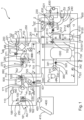
- the proposed heat pump system 1 is a combination of a heat generator for heating and cooling and a ventilation system for temperature control of rooms and/or buildings.
- the heat pump system 1 contains a refrigerant circuit 100, an air/air heat exchanger 200, a hot water tank 300 and a buffer tank 610.
- a three-way valve 710 can be used to heat water or heat/cool rooms.
- a solar system 400 and/or an electric heater 500 can be connected to or integrated in the heat pump system 1 .
- the heat pump system 1 can be composed of two units, a heating module 2 and a storage module 3.
- the modules 2, 3 are assembled in a building/room and form the heat pump system 1, for heating, hot water preparation and ventilation, optionally also for cooling.
- the heat pump system 1 has a refrigerant circuit 100 with a compressor 110, a three-way valve, a gas cooler, a refrigerant sub-cooler, a throttle 150 and an evaporator 160.
- a gas cooler 170 is advantageously provided, which has a heat exchanger 171 for heat exchange between a refrigerant of the refrigerant circuit 100 and a heat transfer medium of a charging circuit 700 .
- An opening 161 is assigned to the evaporator 160, via which the evaporator 160 is connected to outside air.
- the refrigerant circuit 100 lines 180, 184 and 185 on.
- an air/air heat exchanger 200 is also integrated in the heat pump system 1 .
- the air/air heat exchanger 200 is connected to an exhaust air duct 210 , an air supply duct 220 , an exhaust air duct 250 and an outside air duct 280 .
- a supply air fan 221 is preferably arranged in the supply air duct 220 .
- An exhaust air fan 251 is preferably arranged in the exhaust air duct 250 .
- Outside air AU is fed to the air/air heat exchanger 200 via a preheater 270 .
- the outside air AU is preferably heated to a minimum temperature value t M in the preheater 270 .
- the minimum temperature value t M is preferably around -3°C, but at least around -5°C or at a value between -5°C and +3°C.
- the minimum temperature value t M can also depend on an air parameter, in particular on the outside air AU.
- the minimum temperature value t M can depend on the moisture content and/or the temperature of the outside air AU, on the moisture content of the air supplied to the preheater 270 or on other values.
- the air supplied to the pre-heater 270 can be outside air AU, a mixture of outside air AU and exhaust air FO or just exhaust air FO or come from other sources.
- the minimum temperature t M should preferably be in a temperature range between ⁇ 3° C. and 0° C. and can be the described dependency on the temperature of the outside air AU and/or on the humidity of the air supplied to the preheater 270 . At very low temperatures and very low humidity, the minimum temperature t M can tend to be lowered, while it tends to be increased at high humidity contents, for example at temperatures above the freezing point, at 1°C to 3°C in particular.
- the air then flows on from the preheater 270 to the air/air heat exchanger 200 via the outside air duct 280.
- the outside air AU is further heated by heat from the exhaust air AB flowing through the air/air heat exchanger 200 from a room.
- the exhaust air AB of the room is approx. 15-25°, in particular approx. 20°, and heats the air/air with preferably at least the minimum temperature of approx. -5 °C to 3 °C, in particular -3 °C.
- Heat exchanger 200 inflowing outside air AU to temperatures between at least 1 °C to about 20 °C.
- the outside air AU is preferably raised in counterflow to a temperature that is approx. 2 K to 5 K below the temperature of the exhaust air AB from the room.
- the then heated outside air AU flows on as supply air ZU via the supply air duct 220 to an air heater 230.
- the incoming air is raised to a second temperature t GA , which represents a setpoint temperature required for heating the room.
- the heat transfer medium flowing through the air heater 230 has temperatures tw of preferably 30° C.-70° C. there, whereby the supply air flow ZU is raised to a temperature of preferably below 60° C., in particular approximately less than or equal to 50° C.
- the setpoint temperature of the supply air flow ZU is controlled depending on an outside temperature t Au and/or a room temperature. Accordingly, either the mass flow of the heat transfer medium through the air heater 230 and/or the temperature tw of the heat transfer medium is controlled in order to reach the second temperature t GA .
- a supply air temperature sensor is provided in a supply air connection 240, which detects the supply air temperature t Zu .
- the temperature of the heat transfer medium and/or the mass flow of the heat transfer medium is controlled as a function of a temperature signal of the supply air t Zu and/or the room temperature t R and/or the outside temperature t Au .
- the supply air is heated to approx. 50 °C.
- the supply air is heated to around 35 °C.
- the supply air IN is lowered in temperature to a value that is below the room temperature t R . This continues until the setpoint of the room temperature t Rs is reached.
- the supply air temperature for cooling purposes it is necessary for the supply air temperature for cooling purposes to be below the target temperature of the room for longer periods of time, especially for several hours, when the outside temperature is above 25 °C in particular or when there is a high level of heat input from solar radiation t Rs is maintained and the heat transfer medium is cooled.
- the refrigerant circuit 100 is also operated in such a way that the gas cooler 170 serves as a gas heater or evaporator, where the refrigerant absorbs heat from the heat transfer medium and thus cools the heat transfer medium.
- the exhaust air flow AB which flows through the exhaust air duct 210 to the air/air heat exchanger 200, is increased when heating by the cool outside air flow AU, which preferably flows to the air/air heat exchanger 200 at approx. -3 °C to 2 °C Temperatures cooled below room temperature. Depending on the outside temperature, cooling takes place to a temperature value which is approximately 2 K to 7 K above the outside air temperature or the temperature of the air which is supplied to the air/air heat exchanger 200 .
- the exhaust air AB thus flows out of the air/air heat exchanger 200 cooled as exhaust air FO and is preferably conveyed by the exhaust air fan 251 in the exemplary embodiment.
- the exhaust air FO conveyed in this way is supplied to an evaporator 160 of the refrigerant circuit 100 via an exhaust air duct 250 . Since the exhaust air FO is about 2 K to 7 K warmer than the outside air AU, the evaporator 160 is supplied with relatively high-energy air through the exhaust air FO, which preferably has a temperature above the freezing point, which prevents the evaporator 160 from freezing or is delayed.
- the evaporator 160 can be defrosted with the exhaust air FO.
- the heat pump system 1 also has a hot water tank 300 which is preferably heated via a hot water heat exchanger 330 .
- the drinking water in the hot water tank 300 is pumped through the hot water heat exchanger 330 by means of a circulating pump 320 which is located in a pump line 340 .
- the drinking water preferably flows through the water lines 341 and 342 to the hot water heat exchanger 330, which is arranged in a body 310.
- the heat transfer medium is pumped to the hot water heat exchanger 330 by means of the pump 720 .
- the three-way valve is switched by controller 4 between hot water generation and buffer tank loading.
- the three-way valve 710 is switched in such a way that the heat transfer medium is routed to the hot water heat exchanger 330 .
- the three-way valve to the primary flow line 701 is open for heating the buffer storage tank and/or the heat transfer medium circuit 600 .
- a solar system 400 is connected to the heat pump system 1 .
- the solar system 400 consists of a solar collector 41 0, a solar pump 420, a solar heat exchanger 430 and a solar heat transfer medium cooler 431.
- the solar heat transfer medium cooler 431 is preferably integrated into a return line 730 of a charging circuit 700.
- An electric heater 500 with an electric heating element 510 and an electric connection 520 is provided in order to convert direct electrical current into heat and to be able to deliver this heat to the charging circuit 700 .
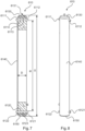
- a buffer memory 610 is also provided, to which a heat transfer medium circuit 600 is connected.
- a fluid line 612 leads to the air heater 230.
- a first buffer tube 6110 is provided in the buffer store 610 .
- the buffer memory 610 has a first entry 6111 and a first exit 6112 .
- the first buffer tube 6110 is equipped with a first tube opening 6113 .
- the first tube opening 6113 is directed upwards to an upper dished end 6130 .
- the first buffer tube 6110 itself is advantageously at least partially continuous with respect to the first tube opening 6113, so that a heat transfer medium flowing through the first buffer tube 6110 is connected to the heat transfer medium located in the buffer reservoir 610 via the first tube opening 6113 directed towards the upper dished end 6130.
- a fluidic connection between the first inlet 6111 and the first outlet 6112 of the first buffer tube 6110 is thus provided.
- the heat transfer medium thus enters the buffer store 610 through the first inlet 6111 and flows in the first buffer pipe 6110 to the first pipe opening 6113. If a buffer pump 620 is running, the heat transfer medium is conveyed. It flows through the first pipe opening 6113 into the buffer reservoir 610 and the heat transfer medium conveyed in this way flows largely directly through the first outlet 6112 of the first buffer pipe 6110 into the heat transfer medium circuit 600. This will depend on the delivery rates at which the buffer pump 620 and a charging pump 720 are running Heat transfer medium partially or fully pumped into the buffer memory 610.
- the heat transfer medium flows directly from the first inlet 6111 to the first outlet 6112 and hardly any heat transfer medium flows through the first pipe opening 6113 into the buffer tank 610.
- the buffer pump 620 for example, delivers less heat transfer medium than the charging pump 720
- the flow of the heat transfer medium is divided on the one hand in the first outlet 6112 according to the flow rate of the buffer pump 620 and on the other hand in the buffer tank 610 itself.
- the difference in the mass flow of the heat transfer medium depending on the flow rate of the charging pump 720 and the buffer pump 620, flows in or out through the first pipe opening 6113 the buffer reservoir 610.
- the heat transfer medium with the temperature TW of the heat transfer medium is thus conveyed into the buffer reservoir 610 and this is loaded or discharged in layers from top to bottom with this temperature Tw.
- the heat transfer medium flows into heat transfer circuit 600 at temperature Tw.
- the buffer memory 610 is equipped with a second inlet 6121 and a second outlet 6122 .
- the second buffer tube 6120 has a second tube opening 6123 which is directed towards a lower dished head 6150 and thus the second buffer tube 6120 is open towards the lower dished head 6150 . Opposite the second tube opening 6123, the second buffer tube 6120 is continuous.
- the first buffer tube 6110 and the second buffer tube 6120 are continuous in the exemplary embodiment, but each have the tube opening 6113, 6123. What is important here is not the continuity of the tube, but rather the best possible flow from the first inlet 6111 to the first outlet 6112, which can also flow through other Measures can be achieved, but so is particularly advantageous.
- two pipes can also be used, which are preferably arranged opposite one another in the buffer storage tank 610 and advantageously have a flow protection 6160, which prevents the stratification of the heat transfer medium at the temperature of the heat transfer medium Tw im Buffer memory 610 is faulty.
- the buffer store 610 has a container wall 6140 between the upper dished head 6130 and the lower dished head 6150 .
- the buffer store 610 has a diameter D and a height H. Furthermore, the cylinder wall is defined by a height Hz of the cylinder wall 6140 .
- the distance from the first buffer tube 6110 to the second buffer tube 6120 is defined by a buffer tube distance R.
- the first buffer pipe 6110 is arranged in an upper zone Z o of the buffer tank 610 .
- the second buffer tube 6120 is arranged in a lower zone Z u of the buffer store 610 .
- the buffer store 610 is very slim, i.e. the ratio of the buffer store diameter D to the height H of the buffer store is low.
- the buffer store 610 has a diameter D of advantageously approx. 15 cm-25 cm, the height H advantageously being between approx. 80 cm and 200 cm, the ratio of diameter and height DIH preferably being less than 0.2 in the exemplary embodiment.
- the diameter D can also be less than 15 cm and the height H can also be greater than 200 cm. Depending on how high the height H is selected, the diameter D can also be larger. If the height H is more than 200 cm, the diameter D can also be more than 25 cm, the ratio of diameter and height preferably remaining less than 0.3 or less than 0.2.
- the diameter D of the buffer store 610 is approximately 18 cm and the height is approximately 150 cm.
- the ratio of the buffer storage diameter D to the height H of the buffer storage 610 is advantageously about 0.12.
- Such ratios of the diameter D to the height H will advantageously be below 0.4, in particular ratios between 0.2 and 0.08, or about 0.1 to 0.14.
- the buffer reservoir 610 advantageously has a vent connection 6131 or a vent valve on the upper dished end 6130 .
- the first buffer tube 6110 is located in the upper zone Z o , which advantageously makes up a volume of less than 25% of the buffer store 610 .
- first inlet 6111, the first outlet 6112, the second inlet 6121 and the second outlet 6122 can also be attached at any point of the buffer store 610, for example in the upper dished end 6130, or in the lower dished end 6150 and/or anywhere in the container wall 6140.
- Pipes are then advantageously fitted inside the buffer store 610, with which the inlets and outlets 6111, 6112, 6121, 6122 are lengthened, the pipes then ending in a designated area of the buffer store 610.
- the first inlet 6111 can be arranged in the lower dished end 6150 and a pipe can be routed in the buffer store 610 up to the area of the upper dished end 6130, where the heat transfer medium can then enter the inner space of the buffer store 610. Physically, this comes close to an arrangement in which the first entry 6111 is attached to a corresponding point in the upper dished end 6130 .
- the buffer tube spacing R is advantageously as large as possible.
- the first buffer tube 6110 is close to the upper dished end 6130, but is still arranged in the container wall 6140, and the second buffer pipe 6120 is also close to the lower dished end 6150, but still arranged in the container wall 6140.
- An arrangement of the first buffer tube 6110 and the second buffer tube 6120 in a dished end 6130, 6150 can also be advantageous, in particular for reasons of manufacturing technology.
- only the same dished heads 6130, 6150 need to be manufactured with a buffer tube 6110, 6120, which are then placed on the container wall 6140 at the top and bottom.
- the buffer pump 620 is provided in the heat transfer circuit 600 , which pumps the heat transfer medium first to the air heater 230 and then to a heating circuit heat exchanger 632 .
- the heating circuit heat exchanger 632 is part of a heating circuit 630.
- a liquid heat transfer medium flows through the heating circuit 630, driven by a heating circuit pump 631. This can be used to supply underfloor heating and/or radiators with heat/cold.
- a buffer bypass 703 is provided in the area of the water hydraulics of the buffer store 610 , which is branched off from a primary flow line 701 by means of a bypass three-way valve 702 .
- a bypass 272 is advantageously provided past the preheater 270 and can be opened or closed via a bypass three-way valve 271 .
- the heat transfer medium flows through the bypass 272 when the outside air AU already has a minimum temperature value t M .
- the heat transfer medium may or may not flow through the preheater 270 . If the outside temperature t Au is lower than the minimum temperature t M , the bypass 272 is closed with the three-way valve 271 and the heat transfer medium flows through the preheater 270 in order to bring the outside air AU to the minimum temperature t Au .
- a buffer tank 610 for a heat pump system 1, with a volume to hold a heat transfer medium, has a height H, a diameter D and at least one inlet 6111, 6121 and at least one outlet 6112, 6922, the buffer tank 610 internally has a ratio between the diameter D and a height H of less than 0.4, in particular less than about 0.2,
- the container wall 6140 is arranged between the upper dished end 6130 and the lower dished end 6150, with the upper buffer pipe 6110 being guided through the tank wall 6140 below the upper dished end 6130 and the lower buffer pipe 6120 being guided through the tank wall 6140 above the lower dished end 6150.
- At least one buffer tube 6110, 6120 advantageously has an opening 6113, 6123 and is directed toward a dished end 6130, 6150.
- the flow temperature is advantageously specified by a controller by setting a heat transfer capacity of the flowing heat transfer fluid, with the heat transfer capacity depending on the flow temperature and a pump capacity of a pump and/or heating capacity of the refrigerant circuit specified by the controller.
- the heat output of the refrigerant circuit is advantageously specified by a speed for the compressor determined by the controller, in particular as a function of the first temperature parameter T1.
- the second temperature t GA of the supply air (ZU) is determined by the controller 4 as a function of a difference between a determined flow temperature tv and an outlet temperature t al of the heat transfer fluid from the air heater 230, an inlet temperature t Ge in the air heater and is determined as a function of an air volume flow of the supply air (ZU), with which the controller in particular regulates the pump output 620 .
- the first temperature parameter T1 and/or the second temperature parameter T2 is determined as a function of a percentage P a of an outside temperature t a and/or as a function of a percentage P R of the room temperature t R .
- the temperature parameter T2 is dependent on the temperature parameter T1, with the temperature parameter T1 being determined in particular by a predetermined heating curve.
- the pump speed of the charging pump 720 and/or the performance of the refrigerant circuit is adjusted in such a way that the heat transfer medium the flow temperature tv is reached, with the heat output being specified by the controller 4 in particular in the interaction of the pump output of the pump 720, 620 with the heating output of the refrigerant circuit.
- outside air AU is brought to a minimum temperature t M in the first heating mode, with temperatures of the outside air below the freezing point, with a preheater through heat exchange with the heat transfer fluid.
- the preheated outside air is fed to an air/air heat exchanger at the minimum temperature tM .
- a measured minimum temperature value t Mm which is measured downstream of the preheater 270 in the flowing outside air AU, is fed to the controller.
- the preheater is advantageously activated as a function of the outside temperature t A and a heat output is set as a function of the measured minimum temperature t Mm .
- the air volume flow of the outside air is advantageously reduced if the minimum temperature t M of the supplied outside air cannot be brought to the minimum temperature t M with the preheater despite full heating output.
- the outside air is advantageously fed to the air/air heat exchanger after the preheater at a minimum temperature of at least between -5 °C and +3 °C, in particular approx -Heat exchanger is further raised to a temperature between approx. 12 °C to 25 °C.
- the outside air at temperatures between 12 °C and 25 °C, is fed to an air heater in the flow direction of the outside air AU after the air/air heat exchanger, with the outside air in the air heater depending on the second temperature parameter T2 being heated to a temperature between 25 °C and 60 °C, which is at least above the room temperature t R in the first heating case, in particular to temperatures between 30 °C and 50 °C, corresponding to a preferably linear dependence on the second temperature parameter T2.
- the heat transfer fluid is advantageously first brought to the flow temperature tv in a gas cooler and then fed to a buffer store with a form factor of diameter to height, DIH, of less than 0.25, in particular less than 0.18.
- the heat transfer fluid is pumped into an upper buffer tube of a buffer stratified storage tank, with the heat transfer fluid having the flow temperature via an upper opening is connected to an upper zone Zo, so that the heat transfer fluid flows into the upper zone Zo of the buffer layer memory.
- the stratified buffer tank is layered downwards from the upper zone Zo, charged with the heat transfer fluid with the flow temperature t M and a volume of the heat transfer medium in the buffer stratified tank with the flow temperature is adjusted to a specified degree of charging with the flow temperature tv.
- the layered buffer storage tank is advantageously charged in layers with a first mass flow from a primary flow line, with a second mass flow being routed via an upper outlet into a fluid line to a heat transfer medium circuit, so that the flow of the heat transfer medium with the flow temperature is divided between the layered buffer storage tank and the heat transfer medium circuit.
- the refrigerant circuit and advantageously also the charging pump are switched off.
- the buffer pump can continue to run and at least the air heater continues to flow through with heat transfer fluid from the buffer storage.
- the power of the refrigerant circuit 100 is reduced or switched off in a second heating mode if the buffer store has a predetermined charge level in the second heating mode.
- the charging pump is advantageously reduced in speed or switched off in the second heating mode and the heating circuit pump continues to be operated in order to pump a specified mass flow of the heat transfer medium with a flow temperature tv from the buffer tank through the heat transfer circuit.
- the heating circuit pump advantageously pumps the heat transfer medium from the upper zone Zo of the stratified storage tank to the air heater, with the heat transfer medium in particular having a temperature close to the flow temperature tv or the flow temperature tv.
- a heat pump system to move CO2 as a refrigerant in the refrigerant circuit, with the CO2 exchanging energy with the heat transfer medium at hot gas temperatures of up to 160 °C, so that the heat transfer medium is heated to up to 90 °C can be and the air is heated in an air heater 230 to a temperature of up to a good 50°.
- the outside air is advantageously heated to at least a minimum temperature in a preheater, if it has temperatures close to or below freezing point, in particular temperatures below 1 °C, but at least to a temperature of approx. -4 °C to +1 °C.
- the air is then further heated in an air/air heat exchanger by the exhaust air coming from a room to approx. 12 °C to 25 °C and then flows into the air heater, where the air is heated from approx.
- a liquid-conducted heating circuit 630 is provided in a heat exchanger 632, which is arranged downstream of the air heater 230 in the flow direction of the heat transfer medium, which can be thermally coupled to the heat transfer medium circuit 600 as required, in particular depending on the first temperature parameter or the second temperature parameter or the outside air is
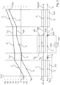
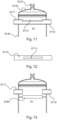
- figure 3 shows a method for heating supply air IN for a room when temperatures outside, from which outside air AU is sucked in, are below freezing.
- T AU is therefore about -25° C. and is brought to a minimum temperature t M in the preheater 270 .
- the minimum temperature t M is advantageously in a range between -5 °C and +3 °C. In the exemplary embodiment, the minimum temperature is -3 °C. This is advantageous when the outside temperature is very low and the air has low humidity. Icing is then relatively unlikely and therefore the preheating does not have to be that high.
- the minimum temperature in the air/air heat exchanger 200 is increased to temperatures above 0°C, in particular to a temperature between 0°C and 3°C.
- the air then flows after the preheater 270 to the air/air heat exchanger 200, where it is brought to a temperature t GR of approx.
- the air to be flown is then brought to a temperature t GA in an air heater 230, with which the room is heated. In a first heating operation, this temperature is above the room temperature t R .
- the second temperature at the outlet of the air heater is greater than the room temperature t R and in the exemplary embodiment is less than or equal to 50°C.
- the heat transfer medium cools down from a flow temperature tv in the air heater 230 to a second flow temperature tV2 .
- additional heat is absorbed by the heating circuit 630 in the exemplary embodiment and delivered to a heat sink 640, this is advantageously a liquid system.
- the heat transfer medium is cooled down from the second flow temperature tvz to a third flow temperature tva.
- This cooling of the heat transfer medium takes place in a heating circuit heat exchanger 632, in which the heat of the heat transfer medium is transferred to a heating circuit liquid of the heating circuit 630.
- the cooling from t V2 to t V3 is approximately 3 K to 10 K.
- the heating circuit heat exchanger 632 is arranged downstream of the preheater 270 and upstream of the air heater 230 in the flow of the heat transfer medium.
- the air/air heat exchanger 200 is arranged on the air side between the air heater 230 and the preheater 270 .
- the air is thus heated in an air/air heat exchanger 200 between the preheater 270 and the air heater 230, while the heat transfer medium is cooled by a liquid, here the heating circuit liquid, through a heat sink 640 of a heating circuit 630.
- the heat transfer medium is cooled by the heat sink 640 in that the heat transfer medium is routed directly into the heating circuit 630 through a three-way switching valve 633 and is thus routed directly to the heat sink 640 .
- the heat transfer medium is thus cooled directly by the heat sink 640 .
- the heat transfer medium flows through a heating circuit heat exchanger 632.
- heating circuit 640 heating fluid is driven around by a pump 631 as required. This is done as in figure 3 in cool temperatures, preferably to heat a floor or a radiator. In this case, the heat transfer medium is not in contact with the heating fluid flowing through the heating circuit 630 . Heat is transferred from the heat transfer medium to the heating circuit liquid via the heating circuit heat exchanger 632 .
- the heat transfer medium thus flows to the preheater 270 after it has given off heat to the heating circuit 630 or heat to the heat sink 640.
- the heat transfer medium is cooled by the outside air to flow at the outside air temperature tv to a return temperature t Stud .
- the return temperature is preferably at temperatures above the freezing point.
- the heat transfer medium can also be cooled to temperatures below freezing.
- the heat transfer medium at the outlet of the preheater 270 is cooled to temperatures in particular between ⁇ 10° C. and 0° C.
- the outside air is thus heated in a first stage in a preheater 270, in which heat is transferred from the full heat transfer medium to the air.
- the air supplied to the room is heated in an air/air heat exchanger and heated to supply air supplied in the room with a second temperature at the outlet of the air heater of up to approx. 50 °C.
- the heat transfer medium is cooled down in three stages, at least in the case of very cold outside temperatures.
- the first stage takes place in the air heater 230, in which the heat transfer medium gives off heat to the supply air.
- the heat transfer medium gives off heat, advantageously in a liquid-based heat exchanger or by conducting the liquid in the heating circuit 630, after which the heat transfer medium heats directly in a preheater to the cold incoming outside air.
- the heat transfer medium is cooled at very low outside temperatures, below 10° C., from temperatures above 50° C., in particular above 70° C., to temperatures below the freezing point.
- the supplied air is raised from temperatures below approx. -7 °C to temperatures of in particular up to 50 °C.
- the heat transfer medium is therefore preferably an antifreeze liquid, in particular brine.
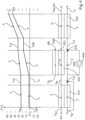
- the heating of the air or the outside air, which is to be supplied to the room as supply air is shown at temperatures slightly above the peak point. In this case, where there are slight plus degrees from 0 °C to approx. -5 °C, preferably as shown in the exemplary embodiment, no heating of the outside air in the preheater 270. In such a heating case, the preheater 270 is bypassed at temperatures which are preferably slightly above the freezing point, preferably by means of a bypass. After that, the air/air heat exchanger 200 is heated to a temperature just below room temperature t R .
- the air then flows to the air heater 230, where it is heated to a predetermined second temperature at the outlet of the air heater t GA , which is in particular between 30° C. and 50° C.
- a predetermined second temperature at the outlet of the air heater t GA which is in particular between 30° C. and 50° C.
- the supplied air with the second temperature at the outlet of the air heater t GA is around 35 °C to 40 °C.
- the heat transfer medium is accordingly cooled in two stages, first heated in the air, to a temperature t V2 and then in the heating circuit 630 or by the heating circuit 630 to a third flow temperature t V3 .
- the third flow temperature t V3 preferably corresponds to the return temperature t R .
- the system is also used for cooling.
- the supply air is cooled in the air/air heat exchanger from an outside temperature, which is preferably above 25° C., to a temperature which is slightly above room temperature t R .
- the supplied air is at an outside temperature from 30 °C or above 30 °C to a temperature slightly above room temperature. This is done by the exhaust air, which flows into the air/air heat exchanger at room temperature t R , preferably at around 20 °C to 25 °C. This means that the exhaust air cools it down. Further cooling then takes place in the air heater 230, which transfers heat from the air to the heat transfer medium during inverse operation of the refrigerant circuit.
- the supply air is cooled to a temperature which is preferably below room temperature in order to cool the room.
- figure 6 shows the case in which the heating circuit 630 is switched off at outside temperatures which are preferably above the freezing point or significantly above the freezing point. Accordingly, there is no heat transfer from the heat transfer medium to the heating circuit 630.
- the outside air is not cooled by the heat transfer medium in the preheater 270 either, since the preheater 270 is surrounded by a bypass and the heat transfer medium does not pass through the preheater 270, but past the air heater 230 through the bypass flows.
- the outside air is therefore supplied to the air/air heat exchanger 200 at around the outside air temperature t AU , where it is raised from the outside air temperature to around 17 °C to 20 °C, at least to a temperature slightly below the room temperature t R .
- a mass or volumetric flow meter V 701 is advantageously arranged in the charging circuit 701 .
- a mass or volume flow meter V 600 is advantageously arranged in the heat carrier circuit 600 .
- At least two of the following sensors for measuring temperatures are advantageously connected to the controller 4, with which the first temperature parameter T1 and/or the second temperature parameter T2 is preferably formed in the controller, with which the performance of the refrigerant circuit, the pumps (620, 720 ) and the temperatures of the heat transfer medium can be controlled: Hot water return temp t WRL Hot water tank flow temp t WProv DHW tank temp T WDHW DHW cylinder integral temp t Wint Domestic hot water tank temp t Wdom Flow temperature hot water heat exchanger Temp t WPWVL Buffer tank return temp t Wrear SET DHW TEMPERATURE T WWset Flow temperature of the heat transfer medium circuit t VHK1 Return temperature heat carrier circuit t RHK2 Temperature of the heat transfer medium downstream of the gas cooler t WPVL Second supply air temperature tGA supply air temperature t to Temperature of the air in front of the air heater 230 t ge Temperature after the air/air heat exchanger t GR exhaust air temperature
- the gas cooler 170 for the heat transfer medium is connected to the refrigerant circuit 100 via a supply line 180 and a line 184 for refrigerant. Furthermore, the compressor 110 is connected to the evaporator 160 via a line 185 . This evaporator 160 is in turn connected to the throttle 150, the throttle 150 being in front of the evaporator 160 in the direction of flow c of the refrigerant. Viewed in the flow direction c, the throttle 150 is behind the gas cooler 170. An opening 161 is provided in front of the evaporator 160 of the refrigerant circuit 100, via which the evaporator 160 can be supplied with outside air AU.
- Outside air AU is supplied through a duct 260 to a preheater 270 at an outside air temperature t Au .
- the outside air AU flows through the preheater 270 and heats up in the process.
- the outside air then flows on to the air/air heat exchanger 200 via an outside air duct 280 .
- the exhaust air AB With the exhaust air AB, the outside air AU is heated with a material separation.
- heat is transferred from the exhaust air AB to the outside air AU.
- the outside air AU heated in this way is conveyed through a supply air duct 220 by a supply air fan 221 and enters the air heater 230 at a temperature t Ge of the supply air ZU.
- the incoming air is heated to the temperature t GA and continues to flow as incoming air at approximately 25° C. to 50° C. via an incoming air connection 240 into a building (not shown) or into an air distribution system of a building (not shown).
- the exhaust air AB cooled in the air/air heat exchanger 200 flows out of the air/air heat exchanger 200 as outgoing air FO.
- the exhaust air is conveyed with an exhaust air fan 251.
- the exhaust air duct 250 is directed towards the evaporator 160 or is connected to the evaporator 160 in such a way that the exhaust air FO is routed to the evaporator 160.
- outside air AU is also advantageous to add outside air AU to the exhaust air FO.
- this outside air AU is mixed into the flowing outgoing air FO by the Venturi principle, and this mixture of outgoing air FO and outside air AU is fed to the evaporator 160 .
- the gas cooler 170 for the heat transfer medium flows through refrigerant, which from the compressor 110 from a low pressure, in particular from about 20 bar - 50 bar, in line 185 to a high pressure, in particular from over 73 bar, in the Lead 180 is compressed.
- refrigerant which from the compressor 110 from a low pressure, in particular from about 20 bar - 50 bar, in line 185 to a high pressure, in particular from over 73 bar, in the Lead 180 is compressed.
- heat is transferred from the refrigerant to the heat transfer medium and then from the heat transfer medium to the supply air.
- the three-way valve 710 is switched in such a way that the heat transfer medium is routed exclusively or at least in part to the hot water heat exchanger 330 .
- the heat transfer medium advantageously also flows through the solar heat exchanger 430.
- the buffer memory 610 serves to store excess heating energy in particular and to release it later when the compressor is switched off or during defrosting.
- the buffer store 610 is advantageously loaded and unloaded in such a way that a high temperature gradient between the buffer outlet 612 in the heating circuit and the buffer return from the heating circuit or the heat transfer medium circuit 600 is maintained in order to optimize the transcritical process in the CO 2 refrigerant circuit.
- the CO 2 cooled in gas cooler 170 is re-evaporated in evaporator 160, to which exhaust air FO and/or outside air AU or a mixture thereof is supplied, and flows in direction d in line 185 to compressor 110
- a room supplied supply air ZU advantageous in several ways Heat is supplied, firstly in the preheater 270, in particular to ensure here that the air/air heat exchanger 200 does not freeze, secondly in the air/air heat exchanger 200, in which the air entering as outside air AU absorbs heat from the exhaust air AB, and a
- the former outside air AU then referred to as supply air ZU, undergoes a third heating in the air heater 230, so that a supply air temperature that is above the required room temperature is provided.
- the supply air ZU is further heated by the supply air fan 221, because the energy converted in the supply air fan 221 is not completely converted into flow energy. At this point of the supply air fan 221, thermal energy that is subject to losses is also supplied as heat to the supply air ZU. However, this so-to-speak fourth air heating is very low compared to the three other heatings of the supply air.
- a heat pump system with air heating is shown, with which a building with a low heating requirement, such as a passive house, of around 1-2 kWh at an outside temperature of around -10 °C to -15 °C can be heated.
- a building with a low heating requirement such as a passive house
- air heating can advantageously be used for complete heating.
- the advantage of the invention lies in particular in the fact that only air is used for heating and a water-filled distribution system can be dispensed with. All of the heat that is supplied to the building for heating is released into the building via the supply air. Therefore, at an outside temperature of approx. -10°C or -15°C, the supply air IN is heated to approx. 40°C to 60°C, in particular approx. 50°C.
- complete heating is advantageously carried out exclusively via the supply air IN or additionally with a heating circuit 630.
- a power of about 300 to 1500 watts is delivered to the rooms with the heating fluid, in particular less than 1000 watts, with a value between 400 and 800 watts having been found to be particularly efficient.
- a heat output of between 1000 and 2500 watts is transmitted via the ventilation system in a standard single-family passive house of approx. 150 m 2 .
- a power ratio between air power and heating fluid power is therefore approximately well above 1. In an example of a passive house with 150 m 2 the air heating power is 2000 W and the heating fluid power is 700 W. Accordingly, the power ratio of the air heating power to the heating fluid power is about 2.6.
- a power ratio of the air heating power to the heating fluid power of greater than two, in particular greater than 2.5, is advantageously specified for a CO2 refrigerant circuit. This advantageously provides a significantly higher air heating capacity of the supply air IN than a heating fluid capacity in the heating circuit 630.
- exhaust air FU and preferably admixed outside air AU are advantageously fed to the evaporator 160 as mixed air.
- a mixture of exhaust air and outside air results in an outside temperature of approx. -15 °C and an exhaust air temperature of approx. -10 °C, which is slightly above the outside air temperature, which is fed to the evaporator.
- CO 2 as a refrigerant
- the air in the air heater 230 only needs to be heated from around 15-20 °C to around 30-50 °C.
- the evaporator 160 of the heat pump is subjected to an air flow that is additionally generated by an evaporator fan 162 .
- the evaporator fan 162 can in particular also work as an exhaust air fan 251 and then conveys exhaust air FO and outside air AU alone, with the exhaust air fan being omitted.
- the evaporator fan is arranged in addition to the exhaust air fan.
- only one exhaust air fan 251 is provided, which, in particular in combination with the opening 161, also sucks in outside air at least indirectly and conveys it to the evaporator.
- a first cyclic process refers to an outside temperature of around 10 to 15 °C with a room temperature of around 20 - 22 °C, which is usually desired.
- the energy of the refrigerant is 425 kJlkg at approx. 10 °C and approx. 45 bar.
- the refrigerant is compressed to approx. 55 °C and approx. 80 bar and has an enthalpy of approx. 438 kJ/kg.
- the refrigerant is routed from the compressor to the gas cooler 170 for the heat transfer medium and releases enthalpy here, so that the refrigerant exiting the gas cooler 170 for the heat transfer medium has an enthalpy of approximately 220 kJ/kg at approx. 10 °C and approx. 80 bar having.
- a further optional advantageous supercooling or heat emission of the refrigerant can take place in that the refrigerant has an enthalpy of 200 kJ/kg at approx. 0° C. at approx. 80 bar.
- the refrigerant can advantageously deliver an enthalpy of approximately 220 to approximately 200 kJ/kg to the outside air AU.
- the refrigerant then flows to the throttle 150 and an expansion takes place in the idealized state to an enthalpy of approx. 200 kJ/kg with a pressure of approx. 43 bar and a temperature of approx. 0°C.
- the refrigerant flows further advantageously to the evaporator 160, where it increases in enthalpy from 200 to 425 kJ/kg at a pressure of approx. 45 bar and to a temperature of 10°C.
- the second process considers an outside temperature of about -5 to -15 °C, in particular about -10 °C.
- Outside air AU and exhaust air FO are then supplied to the evaporator 160 in such a way that the mixed temperature of the mixture of outside air AU and exhaust air FO supplied to the evaporator is slightly above the temperature t AU , in particular at approximately 1-5.degree.
- the refrigerant in the evaporator absorbs 160 enthalpy up to a value of approx. 438 kJ/kg or 440 kJ/kg.
- the refrigerant is then compressed at -5 °C at approx. 30 bar to 68 °C and approx.
- the refrigerant now flows through the gas cooler 170 for the heat transfer medium and the enthalpy is reduced to approximately 290 kJ/kg at 30° C. and is reduced to approximately 80 bar.
- a further optional reduction to approximately 275 kJ/kg at approximately 27° C. and approximately 80 bar then takes place in the gas cooler 170 or in a refrigerant subcooler (not shown).
- the refrigerant is fed to the throttle 150, where its pressure is reduced from about 80 bar to about 30 bar at about -5 °C.
- the refrigerant will advantageously exit the gas cooler 170 for the heat transfer medium at about 26°C.
- the refrigerant On the inlet side of the refrigerant, the refrigerant enters the gas cooler 170 for the heat transfer medium at a temperature tüa of approximately 80°C.
- the supply air is heated from -15 °C to a temperature of at least 40 °C, in particular to approx. 50 °C.
- the air temperature t Ge rises from approx. 16 °C to a temperature value t GA of approx. 50 °C.
- the initial value of the temperature of the refrigerant t Üe is approximately 80 °C and the initial value of the temperature of the refrigerant is approximately 26 °C.
- the refrigerant loses a corresponding enthalpy of approx. 180 - 300 kJ/kg and a corresponding amount of heat is transferred to the air via the heat transfer medium.
- This is also advantageous when hot water is being heated. Only here the temperature difference is lower, at least at the beginning of the hot water preparation, which should start at approx. 35 °C so that a reasonable shower or something similar can take place.
- the temperature t w of the hot water should advantageously be raised to at least 50 °C.
- the air-to-air heat exchanger is advantageously designed as a cross-countercurrent heat exchanger or countercurrent heat exchanger.
Claims (21)
- Installation de pompe à chaleur (1) comprenant :un circuit frigorifique (100) destiné à produire de la chaleur et doté d'un refroidisseur de gaz (170),un échangeur de chaleur air-air (200),un réservoir d'eau chaude (300),un ballon tampon (610),un circuit de charge (700) doté d'une conduite primaire de départ (701), d'une conduite de retour (730) et d'une soupape à trois voies (710), un agent caloporteur pouvant circuler dans le circuit de charge (700), la soupape à trois voies (710) permettant d'effectuer la préparation d'eau chaude ou un chauffage/refroidissement de pièces,le refroidisseur de gaz (170) du circuit frigorifique (100) étant couplé à la conduite primaire de départ (701), en sachant qu'il se trouve tout d'abord, dans le sens de l'écoulement (x) de l'air extérieur entrant dans l'installation de pompe à chaleur (1), un dispositif de préchauffage (270) conçu pour préchauffer, conformément aux besoins, de l'air extérieur (AU) à une valeur de température minimale (tM),en aval du dispositif de préchauffage (270), dans le sens de l'écoulement, il est prévu l'échangeur de chaleur air-air (200), conçu pour chauffer de manière séparée matériellement l'air extérieur au moyen d'air extrait,en aval de l'échangeur de chaleur air-air (200), dans le sens de l'écoulement (x), il est prévu un réchauffeur d'air (230) servant de réchauffeur d'agent caloporteur/d'air, ledit réchauffeur d'air étant conçu pour réguler la température de l'air extérieur à une température d'air entrant (tGA),en sachant que l'on trouve tout d'abord, dans le sens de l'écoulement (z) de l'agent caloporteur, le raccordement du réchauffeur d'air (230) au ballon tampon (610) par le biais d'une conduite de fluide (612), ledit réchauffeur d'air étant également raccordé à un canal d'air entrant (220) et à un raccord pour air entrant (240), et que l'on trouve ensuite, dans le sens de l'écoulement (z) de l'agent caloporteur, le raccordement du dispositif de préchauffage (270) au ballon tampon (610).
- Installation de pompe à chaleur (1) selon la revendication 1, caractérisée en ce que le dispositif de préchauffage (270) présente un raccord pour air extérieur (260) et le réchauffeur d'air (230) est relié à un raccord de bâtiment/raccord pour air entrant.
- Installation de pompe à chaleur (1) selon la revendication 2, caractérisée en ce que l'échangeur de chaleur air-air (200) présente un canal d'air extrait (210) pour l'air extrait (AB), un canal d'air entrant (220) pour l'air entrant (ZU), un canal d'air rejeté (250) pour l'air rejeté (FO), l'échangeur de chaleur air-air (200) étant de préférence équipé de telle manière que l'air rejeté (FO) peut s'écouler, entraîné par un ventilateur à air rejeté (251), à contre-courant de l'écoulement d'air extérieur (AU) entraîné par un ventilateur à air entrant (221).
- Installation de pompe à chaleur (1) selon l'une quelconque des revendications précédentes,
caractérisée en ce quela conduite primaire de départ (701) est raccordée, par le biais d'une première entrée (6111) du ballon tampon (610), à un premier tuyau tampon (6110) traversant une zone supérieure (Zo) du ballon tampon (610) dans laquelle le premier tuyau tampon (6110) présente au moins une première ouverture de tuyau (6113), la conduite de retour (730) est raccordée à un second tuyau tampon (6120) par le biais d'une seconde sortie (6122),le second tuyau tampon (6120) traversant une zone inférieure (Zu) du ballon tampon (610) et le second tuyau tampon (6120) présentant au moins une seconde ouverture de tuyau (6123). - Installation de pompe à chaleur (1) selon la revendication 4,
caractérisée en ce que
l'intérieur du ballon tampon (610) présente un rapport entre diamètre (D) et hauteur (H) inférieur à 0,25, en particulier inférieur à environ 0,15. - Installation de pompe à chaleur (1) selon la revendication 5, comprenant un ballon tampon qui présente un volume destiné à recevoir un agent caloporteur, avec une hauteur (H), un diamètre (D), au moins une entrée (6111, 6121) et au moins une sortie (6112, 6122),
caractérisée en ce que
l'intérieur du ballon tampon (610) présente un rapport entre diamètre (D) et hauteur (H) inférieur à 0,4 ou inférieur à 0,2, en particulier des rapports compris entre 0,07 et 0,1 ou environ 0,1 à 0,2. - Installation de pompe à chaleur selon la revendication 6,caractérisée en ce que le ballon tampon (610) présente une paroi de réservoir (6140) entre un fond bombé supérieur (6130) et un fond bombé inférieur (6150), un tuyau tampon supérieur (6110) traversant la paroi de réservoir (6140) en dessous du fond bombé supérieur (6130) etun tuyau tampon inférieur (6120) traversant la paroi de réservoir (6140) au-dessus du fond bombé inférieur (6150).
- Installation de pompe à chaleur selon la revendication 6 ou 7,
caractérisée en ce qu'au moins un tuyau tampon (6110, 6120) présente au moins une ouverture (6113, 6123), en particulier une fente, et en ce que le tuyau tampon (6110, 6120) est orienté vers un fond bombé (6130, 6150) qui présente au moins une ouverture (6113, 6123). - Procédé de fonctionnement d'une installation de pompe à chaleur (1) qui comprendun circuit frigorifique (100) destiné à produire de la chaleur et doté d'un refroidisseur de gaz (170), un échangeur de chaleur air-air (200),un réservoir d'eau chaude (300), un ballon tampon (610), un circuit de charge (700) doté d'une conduite primaire de départ (701), d'une conduite de retour (730) et d'une soupape à trois voies (710), un agent caloporteur pouvant circuler dans le circuit de charge (700), la soupape à trois voies (710) permettant d'effectuer la préparation d'eau chaude ou un chauffage/refroidissement de pièces, le refroidisseur de gaz (170) du circuit frigorifique (100) étant couplé à la conduite primaire de départ (701),dans lequel il se trouve tout d'abord, dans le sens de l'écoulement (x) de l'air extérieur entrant dans l'installation de pompe à chaleur (1), un dispositif de préchauffage (270) conçu pour préchauffer, conformément aux besoins, de l'air extérieur (AU) à une valeur de température minimale (tM),dans lequel, en aval du dispositif de préchauffage (270), dans le sens de l'écoulement, il est prévu l'échangeur de chaleur air-air (200), conçu pour chauffer de manière séparée matériellement l'air extérieur au moyen d'air extrait,dans lequel, en aval de l'échangeur de chaleur air-air (200), dans le sens de l'écoulement (x), il est prévu un réchauffeur d'air (230) servant de réchauffeur d'agent caloporteur/d'air, ledit réchauffeur d'air étant conçu pour réguler la température de l'air extérieur à une température d'air entrant (tGA),un ballon tampon (610) avec un fluide caloporteur régulé en température par un circuit frigorifique (100) étant amené à une température départ (tv) dans un premier mode de chauffage, ledit fluide caloporteur étant pompé dans un sens d'écoulement (y) au moyen d'une pompe de chargement (720),comportant les étapes de procédé selon lesquellesle fluide caloporteur est chauffé, dans le premier mode de chauffage, à la température départ (tv) grâce au réglage d'une puissance de chauffe du circuit frigorifique (100) de l'installation de pompe à chaleur (1) en fonction d'un premier paramètre de température (T1),de l'air entrant (ZU) étant chauffé à une seconde température (tGA), en fonction d'un second paramètre de température (T2), dans un réchauffeur d'air (230) dans lequel circule le fluide caloporteur dans un sens d'écoulement (z), la seconde température (tGA) étant, dans le premier mode de chauffage, supérieure à une température ambiante de consigne (tRsoll) pour le chauffage d'une pièce.
- Procédé selon la revendication 9, comportant les étapes de procédé selon lesquelles la température départ (tv) est définie au moyen d'un régulateur (4) par le réglage de la capacité caloporteuse du fluide caloporteur s'écoulant, la capacité caloporteuse dépendant de la température départ (tv) ainsi que de la puissance de circulation d'une pompe (720, 620) et/ou de la puissance de chauffe du circuit frigorifique définies par le régulateur (4).
- Procédé selon l'une des revendications précédentes 9 ou 10, comportant l'étape de procédé selon lesquelles la puissance de chauffe du circuit frigorifique (100) est définie par une vitesse de rotation définie par le régulateur (4) pour un compresseur (110), en particulier en fonction du premier paramètre de température (T1).
- Procédé selon l'une des revendications précédentes 9 à 11, comportant les étapes de procédé selon lesquelles la seconde température (tGA) de l'air entrant (ZU) est déterminée par le régulateur (4) en fonction d'une différence entre une température départ (tv) déterminée et une température de sortie (tAI) du fluide caloporteur sortant du réchauffeur d'air (230), d'une température d'entrée (tGe) de l'air dans le réchauffeur d'air (230) et en fonction d'un débit volumétrique de l'air entrant (ZU), moyennant quoi le régulateur (4) règle en particulier la puissance de circulation de la pompe (620, 720).
- Procédé selon l'une des revendications précédentes 9 à 12, comportant les étapes de procédé selon lesquelles la vitesse de rotation de la pompe de chargement (720) et/ou la puissance du circuit frigorifique est/sont réglées de telle manière que l'agent caloporteur atteint la température départ (tv), la puissance calorifique étant définie par le régulateur (4) en particulier avec la puissance de circulation de la pompe (720, 620) combinée à la puissance de chauffe du circuit frigorifique.
- Procédé selon de l'une des revendications précédentes 9 à 13,
comportant les étapes de procédé selon lesquelles
dans le cas de températures de l'air extérieur (tAU) au-dessous de zéro, l'air extérieur (AU) est amené, dans un premier mode de chauffage, à une température minimale (tM) au moyen d'un dispositif de préchauffage (270) par échange de chaleur avec le fluide caloporteur, l'air extérieur préchauffé à la température minimale (tM) est introduit, en aval du dispositif de préchauffage (270), dans un échangeur de chaleur air-air (200), une valeur de température minimale mesurée (tMm), qui est déterminée, dans le sens de l'écoulement (x), en aval du dispositif de préchauffage (270) de l'air extérieur AU en circulation, étant transmise au régulateur, le dispositif de préchauffage (270) étant activé en fonction de la température extérieure (tAu) et une puissance calorifique étant en particulier réglée en fonction de la température minimale mesurée (tMm). - Procédé selon l'une des revendications 9 à 14,
comportant les étapes de procédé selon lesquelles
l'air extérieur (AU), en aval du dispositif de préchauffage (270), est introduit dans l'échangeur de chaleur air-air (200) à une température minimale (tM) d'au moins -5 °C à +3 °C, en particulier d'environ 1 °C, l'air extérieur (AU) étant élevé à une température comprise entre environ 12 °C et 25 °C par échange avec l'énergie thermique de l'air extrait (AB). - Procédé selon l'une des revendications 9 à 15,
comportant les étapes de procédé selon lesquelles
l'air extérieur (AU), à des températures comprises entre 12 °C et 25 °C, est introduit, en aval de l'échangeur de chaleur air-air (200), vu dans le sens de l'écoulement (x) de l'air extérieur (AU), dans un réchauffeur d'air (230), l'air extérieur (AU) étant chauffé dans le réchauffeur d'air (230), en particulier en fonction du second paramètre de température (T2), à une température comprise entre 25 °C et 60 °C qui est supérieure à la température ambiante (tR), en particulier à des températures comprises entre 30 °C et 50 °C conformément à une dépendance de préférence linéaire au second paramètre de température (T2). - Procédé selon l'une des revendications précédentes 9 à 16,
comportant les étapes de procédé selon lesquelles
le fluide caloporteur est d'abord amené à la température départ (tv) dans un refroidisseur de gaz (170) et ensuite introduit dans un ballon tampon (610) ayant un facteur de forme du diamètre par rapport à la hauteur inférieur à 0,25, en particulier inférieur à 0,18. - Procédé selon l'une des revendications précédentes 9 à 17,
comportant les étapes de procédé selon lesquelles
le ballon tampon (610) est chargé par couches avec un premier débit massique provenant d'une conduite primaire de départ (701), un second débit massique étant guidé, par le biais d'une sortie supérieure (6112), dans une conduite de fluide (612) jusqu'à un circuit de fluide caloporteur (600), de telle sorte qu'une répartition de l'écoulement de l'agent caloporteur à la température départ (tv) est prévue selon les besoins entre le ballon tampon (610) et le circuit de fluide caloporteur (600). - Procédé selon l'une des revendications précédentes 9 à 18,
comportant les étapes de procédé selon lesquelles
l'air extérieur (AU), dans la mesure où il présente des températures proches ou au-dessous de zéro, en particulier des températures inférieures à 1 °C, est chauffé dans un dispositif de préchauffage (270) à au moins environ 1 °C, tout du moins à une température comprise entre -4 °C et +1 °C, puis est chauffé davantage pour atteindre entre environ 12 °C et 25 °C dans un échangeur de chaleur air-air par de l'air extrait s'écoulant hors d'un bâtiment, et s'écoule ensuite dans le réchauffeur d'air (230), dans lequel l'air d'une température d'environ 12 °C à 25 °C est porté de préférence à moins de 60 °C, en particulier entre 30 °C et 50 °C, et l'air pénètre au moins dans une pièce ou un bâtiment en tant qu'air entrant (ZU) et la pièce et le bâtiment sont chauffés avec l'air entrant (ZU) chauffé ayant une température s'élevant, en particulier, à 50 °C ou moins. - Procédé selon l'une des revendications 9 à 19 pour le fonctionnement d'un appareil de chauffage et ventilation (1) avec récupération de chaleur, dans lequel de l'air extérieur (AU) passe par un échangeur de chaleur air-air (200) ; l'air extérieur (AU) absorbe, dans l'échangeur de chaleur (200), de la chaleur provenant d'air extrait (AB) ; de l'air rejeté (FO) servant de source de chaleur est guidé hors de l'échangeur de chaleur air-air (200) vers un évaporateur (160) d'une pompe à chaleur pour faire s'évaporer un fluide frigorigène se trouvant dans un circuit frigorifique (100), et de l'air extérieur (AU) pouvant être mélangé à l'air rejeté (FO) pour obtenir un contenu énergétique suffisant, caractérisé par les étapes de procédé selon lesquelles- l'air entrant (ZU) chauffé par l'échangeur de chaleur air-air (200) à une première température (tGe) d'environ 15 à 20 °C est chauffé dans un réchauffeur d'air (230) à une seconde température (tGA) qui est supérieure à une température (tAB) de l'air extrait (AB),- dans un refroidisseur de gaz (170) d'un échangeur de chaleur (171), du CO2 servant de fluide frigorigène dans un état supercritique transfère de la chaleur à un agent caloporteur,- dans le refroidisseur de gaz (170), le fluide frigorigène est refroidi pour passer d'un premier état avec une première température (tüe) qui est supercritique, à un second état avec une seconde température (tÜa) à une pression presque isobare qui est comprise entre environ 73,8 bar et 90 bar,- le CO2 est dilaté dans son sens d'écoulement (c) en amont de l'évaporateur (160) par un restricteur (150) à une pression inférieure à 73 bar et- l'agent caloporteur transfère, dans le réchauffeur d'air (230), de la chaleur à l'air entrant (ZU).
- Installation de pompe à chaleur (1) selon l'une des revendications précédentes 1 à 8,dans laquelle l'échangeur de chaleur air-air (200) sert à transmettre de l'énergie thermique provenant d'un flux d'air extrait (AB) de pièces à chauffer à un flux d'air extérieur (AU), et comportantun circuit frigorifique (100) doté d'un évaporateur (160) qui peut être soumis à l'action d'un flux d'air rejeté (FO) provenant d'un canal d'air rejeté (250), d'une ouverture (161) pour air extérieur en amont de l'évaporateur (160), par laquelle l'air extérieur (AU) peut être mélangé à l'air rejeté (FO) pour obtenir un contenu énergétique suffisant pour servir de source de chaleur,- le refroidisseur de gaz (170) du circuit frigorifique (100) étant disposé dans un circuit d'agent caloporteur qui présente un réchauffeur d'air (230) disposé dans un canal d'air entrant (220),- le réchauffeur d'air (230) étant disposé en aval de l'échangeur de chaleur air-air (200) dans le sens de l'écoulement de l'air (x) de l'air entrant (ZU),- du CO2 servant de fluide frigorigène se trouvant dans le circuit frigorifique,- et de la chaleur provenant du CO2 supercritique servant de fluide frigorigène étant transmise à l'agent caloporteur dans le circuit de fluide caloporteur puis, dans le réchauffeur d'air (230), à l'air entrant (ZU) en aval de l'échangeur de chaleur air-air (200).
Applications Claiming Priority (2)
| Application Number | Priority Date | Filing Date | Title |
|---|---|---|---|
| DE102017003355.2A DE102017003355A1 (de) | 2017-04-06 | 2017-04-06 | Wärmepumpenanlage |
| PCT/EP2018/058726 WO2018185220A2 (fr) | 2017-04-06 | 2018-04-05 | Installation de pompe à chaleur |
Publications (2)
| Publication Number | Publication Date |
|---|---|
| EP3607249A2 EP3607249A2 (fr) | 2020-02-12 |
| EP3607249B1 true EP3607249B1 (fr) | 2023-07-19 |
Family
ID=61972509
Family Applications (1)
| Application Number | Title | Priority Date | Filing Date |
|---|---|---|---|
| EP18717879.3A Active EP3607249B1 (fr) | 2017-04-06 | 2018-04-05 | Installation de pompe à chaleur |
Country Status (3)
| Country | Link |
|---|---|
| EP (1) | EP3607249B1 (fr) |
| DE (1) | DE102017003355A1 (fr) |
| WO (1) | WO2018185220A2 (fr) |
Families Citing this family (4)
| Publication number | Priority date | Publication date | Assignee | Title |
|---|---|---|---|---|
| US20220018571A1 (en) * | 2018-12-07 | 2022-01-20 | Daikin Industries, Ltd. | Air-conditioner |
| AT521703B1 (de) * | 2019-03-20 | 2020-04-15 | Ortner Ges M B H | Warmwasserbereitungsanlage |
| DE102021102438A1 (de) | 2021-02-03 | 2022-08-04 | Viessmann Climate Solutions Se | Wärmepumpenanlage und Verfahren zum Betrieb einer Wärmepumpenanlage |
| DE102022110339A1 (de) | 2022-04-28 | 2023-11-02 | Viessmann Climate Solutions Se | Wärmepumpenanlage und Verfahren zum Betrieb einer Wärmepumpenanlage |
Family Cites Families (13)
| Publication number | Priority date | Publication date | Assignee | Title |
|---|---|---|---|---|
| DE2804748C2 (de) * | 1978-02-04 | 1980-04-10 | Wilhelm 4836 Herzebrock Reckord | Wärme-isolierter Behälter für warmes Wasser o.a. Flüssigkeiten |
| US4365483A (en) * | 1981-07-01 | 1982-12-28 | Binger Larry W | Vertical convection heat dissipation tower |
| DE19702903C2 (de) | 1997-01-28 | 2000-08-24 | Stiebel Eltron Gmbh & Co Kg | Klimaanlage mit einer Wärmepumpe |
| EP1616133B1 (fr) * | 2003-04-23 | 2008-10-22 | Fraunhofer-Gesellschaft zur Förderung der angewandten Forschung e.V. | Evaporateur combine fluide/air et concept de branchement d'une pompe a chaleur dans un appareil de ventilation |
| DE102005002282B4 (de) | 2005-01-18 | 2021-07-22 | Stiebel Eltron Gmbh & Co. Kg | Wärmepumpenkreis einer Lüftungsanlage |
| AT502029B1 (de) * | 2005-06-09 | 2007-01-15 | Drexel Und Weiss Energieeffizi | Einrichtung zur belüftung und beheizung von gebäuden |
| GB0600274D0 (en) | 2006-01-09 | 2006-02-15 | Oxycell Holding Bv | Cooling and ventilation device |
| DE202010014435U1 (de) * | 2010-10-20 | 2011-04-07 | Comfort Sinusverteiler Gmbh | Hydraulische Weiche einer Heiz- oder Kühlanlage |
| AT510440B1 (de) * | 2011-01-17 | 2012-04-15 | Forstner Maximilian | Fluidspeicher |
| EP2620715B1 (fr) * | 2012-01-26 | 2014-01-22 | STIEBEL ELTRON GmbH & Co. KG | Procédé de fonctionnement d'un appareil de chauffage et d'aération et appareil de chauffage et d'aération |
| JP5831467B2 (ja) * | 2013-01-23 | 2015-12-09 | 株式会社デンソー | 暖房システム |
| JP5983451B2 (ja) * | 2013-02-08 | 2016-08-31 | 株式会社デンソー | 暖房システム |
| EP2821727B1 (fr) * | 2013-07-05 | 2016-03-16 | Stiebel Eltron GmbH & Co. KG | Procédé de fonctionnement d'un appareil de chauffage et d'aération et appareil de chauffage et d'aération |
-
2017
- 2017-04-06 DE DE102017003355.2A patent/DE102017003355A1/de active Pending
-
2018
- 2018-04-05 EP EP18717879.3A patent/EP3607249B1/fr active Active
- 2018-04-05 WO PCT/EP2018/058726 patent/WO2018185220A2/fr unknown
Also Published As
| Publication number | Publication date |
|---|---|
| DE102017003355A1 (de) | 2018-10-11 |
| WO2018185220A2 (fr) | 2018-10-11 |
| EP3607249A2 (fr) | 2020-02-12 |
| WO2018185220A3 (fr) | 2018-12-27 |
Similar Documents
| Publication | Publication Date | Title |
|---|---|---|
| AT502029B1 (de) | Einrichtung zur belüftung und beheizung von gebäuden | |
| EP3607249B1 (fr) | Installation de pompe à chaleur | |
| DE60107901T2 (de) | Heisswasserzufuhrsystem mit einem Wärmepumpenkreis | |
| EP2821727B1 (fr) | Procédé de fonctionnement d'un appareil de chauffage et d'aération et appareil de chauffage et d'aération | |
| EP2331880B1 (fr) | Procédé et dispositif pour obtenir de l'énergie thermique utile | |
| EP2620715B1 (fr) | Procédé de fonctionnement d'un appareil de chauffage et d'aération et appareil de chauffage et d'aération | |
| DE1604205A1 (de) | Klimaanlage | |
| DE202009006988U1 (de) | Warmwasserversorgungsanlage mit einem Warmwasserspeicher | |
| DE2700123A1 (de) | Klimaanlage mit waermepumpe | |
| DE2751003A1 (de) | Waermepumpensystem mit einer luftquelle und einem drehkolbenkompressor/entspanner mit mehreren schieberventilen | |
| DE102009004501B4 (de) | Wärmepumpe und Verfahren zur Regelung der Quelleneingangstemperatur an der Wärmepumpe | |
| DE10118572B4 (de) | Wärmeversorgungssystem | |
| EP3702181A1 (fr) | Pompe à chaleur à régulation partielle de la charge | |
| DE102012208139A1 (de) | Wärmepumpenvorrichtung | |
| WO2019012146A1 (fr) | Ensemble pompe à chaleur doté d'un échangeur de chaleur pouvant être commandé et procédé de fonctionnement d'un ensemble pompe à chaleur | |
| DE60128827T2 (de) | Umkehrbares system zur wiederegwinnung von wärmeenergie | |
| AT507709A1 (de) | Einrichtung zur wärmegewinnung | |
| DE102015117851A1 (de) | Fluidsystem und Verfahren zum Steuern eines Fluidsystems | |
| EP1878974A1 (fr) | Accumulateur combiné | |
| DE2509965B2 (de) | Verfahren zur Raumheizung mittels Wärmepumpenkreislauf | |
| DE19900358A1 (de) | Kombinierte Heizungs-/Lüftungsanlage, insbesondere für Niedrigenergiehäuser | |
| DE102008020637A1 (de) | Warmwasserversorgungsanlage mit einem Warmwasserspeicher | |
| DE102017107450A1 (de) | Wärmepumpenanlage zur Temperierung und/oder Belüftung von Räumen und/oder Gebäuden sowie zur Bereitstellung von Warmwasser | |
| AT517021B1 (de) | Wärmetausch-Einrichtung | |
| DE19861020C1 (de) | Lüftungsanordnung für Gebäude |
Legal Events
| Date | Code | Title | Description |
|---|---|---|---|
| STAA | Information on the status of an ep patent application or granted ep patent |
Free format text: STATUS: UNKNOWN |
|
| STAA | Information on the status of an ep patent application or granted ep patent |
Free format text: STATUS: THE INTERNATIONAL PUBLICATION HAS BEEN MADE |
|
| PUAI | Public reference made under article 153(3) epc to a published international application that has entered the european phase |
Free format text: ORIGINAL CODE: 0009012 |
|
| STAA | Information on the status of an ep patent application or granted ep patent |
Free format text: STATUS: REQUEST FOR EXAMINATION WAS MADE |
|
| 17P | Request for examination filed |
Effective date: 20191106 |
|
| AK | Designated contracting states |
Kind code of ref document: A2 Designated state(s): AL AT BE BG CH CY CZ DE DK EE ES FI FR GB GR HR HU IE IS IT LI LT LU LV MC MK MT NL NO PL PT RO RS SE SI SK SM TR |
|
| AX | Request for extension of the european patent |
Extension state: BA ME |
|
| DAV | Request for validation of the european patent (deleted) | ||
| DAX | Request for extension of the european patent (deleted) | ||
| STAA | Information on the status of an ep patent application or granted ep patent |
Free format text: STATUS: EXAMINATION IS IN PROGRESS |
|
| STAA | Information on the status of an ep patent application or granted ep patent |
Free format text: STATUS: EXAMINATION IS IN PROGRESS |
|
| 17Q | First examination report despatched |
Effective date: 20201113 |
|
| GRAP | Despatch of communication of intention to grant a patent |
Free format text: ORIGINAL CODE: EPIDOSNIGR1 |
|
| STAA | Information on the status of an ep patent application or granted ep patent |
Free format text: STATUS: GRANT OF PATENT IS INTENDED |
|
| RIC1 | Information provided on ipc code assigned before grant |
Ipc: F25B 30/02 20060101ALI20221005BHEP Ipc: F24D 11/02 20060101ALI20221005BHEP Ipc: F24D 17/02 20060101ALI20221005BHEP Ipc: F24D 19/10 20060101ALI20221005BHEP Ipc: F24F 12/00 20060101ALI20221005BHEP Ipc: F25B 9/00 20060101ALI20221005BHEP Ipc: F24D 3/08 20060101ALI20221005BHEP Ipc: F24D 5/12 20060101AFI20221005BHEP |
|
| INTG | Intention to grant announced |
Effective date: 20221024 |
|
| GRAJ | Information related to disapproval of communication of intention to grant by the applicant or resumption of examination proceedings by the epo deleted |
Free format text: ORIGINAL CODE: EPIDOSDIGR1 |
|
| STAA | Information on the status of an ep patent application or granted ep patent |
Free format text: STATUS: EXAMINATION IS IN PROGRESS |
|
| GRAP | Despatch of communication of intention to grant a patent |
Free format text: ORIGINAL CODE: EPIDOSNIGR1 |
|
| STAA | Information on the status of an ep patent application or granted ep patent |
Free format text: STATUS: GRANT OF PATENT IS INTENDED |
|
| INTC | Intention to grant announced (deleted) | ||
| INTG | Intention to grant announced |
Effective date: 20230214 |
|
| GRAS | Grant fee paid |
Free format text: ORIGINAL CODE: EPIDOSNIGR3 |
|
| GRAA | (expected) grant |
Free format text: ORIGINAL CODE: 0009210 |
|
| STAA | Information on the status of an ep patent application or granted ep patent |
Free format text: STATUS: THE PATENT HAS BEEN GRANTED |
|
| P01 | Opt-out of the competence of the unified patent court (upc) registered |
Effective date: 20230519 |
|
| AK | Designated contracting states |
Kind code of ref document: B1 Designated state(s): AL AT BE BG CH CY CZ DE DK EE ES FI FR GB GR HR HU IE IS IT LI LT LU LV MC MK MT NL NO PL PT RO RS SE SI SK SM TR |
|
| REG | Reference to a national code |
Ref country code: GB Ref legal event code: FG4D Free format text: NOT ENGLISH |
|
| REG | Reference to a national code |
Ref country code: CH Ref legal event code: EP |
|
| REG | Reference to a national code |
Ref country code: DE Ref legal event code: R096 Ref document number: 502018012736 Country of ref document: DE |
|
| REG | Reference to a national code |
Ref country code: IE Ref legal event code: FG4D Free format text: LANGUAGE OF EP DOCUMENT: GERMAN |
|
| REG | Reference to a national code |
Ref country code: SE Ref legal event code: TRGR |
|
| REG | Reference to a national code |
Ref country code: LT Ref legal event code: MG9D |
|
| REG | Reference to a national code |
Ref country code: NL Ref legal event code: MP Effective date: 20230719 |
|
| PG25 | Lapsed in a contracting state [announced via postgrant information from national office to epo] |
Ref country code: NL Free format text: LAPSE BECAUSE OF FAILURE TO SUBMIT A TRANSLATION OF THE DESCRIPTION OR TO PAY THE FEE WITHIN THE PRESCRIBED TIME-LIMIT Effective date: 20230719 |
|
| PG25 | Lapsed in a contracting state [announced via postgrant information from national office to epo] |
Ref country code: GR Free format text: LAPSE BECAUSE OF FAILURE TO SUBMIT A TRANSLATION OF THE DESCRIPTION OR TO PAY THE FEE WITHIN THE PRESCRIBED TIME-LIMIT Effective date: 20231020 |
|
| PG25 | Lapsed in a contracting state [announced via postgrant information from national office to epo] |
Ref country code: IS Free format text: LAPSE BECAUSE OF FAILURE TO SUBMIT A TRANSLATION OF THE DESCRIPTION OR TO PAY THE FEE WITHIN THE PRESCRIBED TIME-LIMIT Effective date: 20231119 |
|
| PG25 | Lapsed in a contracting state [announced via postgrant information from national office to epo] |
Ref country code: RS Free format text: LAPSE BECAUSE OF FAILURE TO SUBMIT A TRANSLATION OF THE DESCRIPTION OR TO PAY THE FEE WITHIN THE PRESCRIBED TIME-LIMIT Effective date: 20230719 Ref country code: PT Free format text: LAPSE BECAUSE OF FAILURE TO SUBMIT A TRANSLATION OF THE DESCRIPTION OR TO PAY THE FEE WITHIN THE PRESCRIBED TIME-LIMIT Effective date: 20231120 Ref country code: NO Free format text: LAPSE BECAUSE OF FAILURE TO SUBMIT A TRANSLATION OF THE DESCRIPTION OR TO PAY THE FEE WITHIN THE PRESCRIBED TIME-LIMIT Effective date: 20231019 Ref country code: LV Free format text: LAPSE BECAUSE OF FAILURE TO SUBMIT A TRANSLATION OF THE DESCRIPTION OR TO PAY THE FEE WITHIN THE PRESCRIBED TIME-LIMIT Effective date: 20230719 Ref country code: LT Free format text: LAPSE BECAUSE OF FAILURE TO SUBMIT A TRANSLATION OF THE DESCRIPTION OR TO PAY THE FEE WITHIN THE PRESCRIBED TIME-LIMIT Effective date: 20230719 Ref country code: IS Free format text: LAPSE BECAUSE OF FAILURE TO SUBMIT A TRANSLATION OF THE DESCRIPTION OR TO PAY THE FEE WITHIN THE PRESCRIBED TIME-LIMIT Effective date: 20231119 Ref country code: HR Free format text: LAPSE BECAUSE OF FAILURE TO SUBMIT A TRANSLATION OF THE DESCRIPTION OR TO PAY THE FEE WITHIN THE PRESCRIBED TIME-LIMIT Effective date: 20230719 Ref country code: GR Free format text: LAPSE BECAUSE OF FAILURE TO SUBMIT A TRANSLATION OF THE DESCRIPTION OR TO PAY THE FEE WITHIN THE PRESCRIBED TIME-LIMIT Effective date: 20231020 Ref country code: FI Free format text: LAPSE BECAUSE OF FAILURE TO SUBMIT A TRANSLATION OF THE DESCRIPTION OR TO PAY THE FEE WITHIN THE PRESCRIBED TIME-LIMIT Effective date: 20230719 |
|
| PG25 | Lapsed in a contracting state [announced via postgrant information from national office to epo] |
Ref country code: PL Free format text: LAPSE BECAUSE OF FAILURE TO SUBMIT A TRANSLATION OF THE DESCRIPTION OR TO PAY THE FEE WITHIN THE PRESCRIBED TIME-LIMIT Effective date: 20230719 |