EP3607201B1 - Elektromagnetische pumpe - Google Patents
Elektromagnetische pumpe Download PDFInfo
- Publication number
- EP3607201B1 EP3607201B1 EP18713956.3A EP18713956A EP3607201B1 EP 3607201 B1 EP3607201 B1 EP 3607201B1 EP 18713956 A EP18713956 A EP 18713956A EP 3607201 B1 EP3607201 B1 EP 3607201B1
- Authority
- EP
- European Patent Office
- Prior art keywords
- magnetic field
- conduit
- field generating
- piston member
- generating unit
- Prior art date
- Legal status (The legal status is an assumption and is not a legal conclusion. Google has not performed a legal analysis and makes no representation as to the accuracy of the status listed.)
- Active
Links
Images




Classifications
-
- F—MECHANICAL ENGINEERING; LIGHTING; HEATING; WEAPONS; BLASTING
- F04—POSITIVE - DISPLACEMENT MACHINES FOR LIQUIDS; PUMPS FOR LIQUIDS OR ELASTIC FLUIDS
- F04B—POSITIVE-DISPLACEMENT MACHINES FOR LIQUIDS; PUMPS
- F04B17/00—Pumps characterised by combination with, or adaptation to, specific driving engines or motors
- F04B17/03—Pumps characterised by combination with, or adaptation to, specific driving engines or motors driven by electric motors
- F04B17/04—Pumps characterised by combination with, or adaptation to, specific driving engines or motors driven by electric motors using solenoids
- F04B17/046—Pumps characterised by combination with, or adaptation to, specific driving engines or motors driven by electric motors using solenoids the fluid flowing through the moving part of the motor
-
- F—MECHANICAL ENGINEERING; LIGHTING; HEATING; WEAPONS; BLASTING
- F04—POSITIVE - DISPLACEMENT MACHINES FOR LIQUIDS; PUMPS FOR LIQUIDS OR ELASTIC FLUIDS
- F04B—POSITIVE-DISPLACEMENT MACHINES FOR LIQUIDS; PUMPS
- F04B19/00—Machines or pumps having pertinent characteristics not provided for in, or of interest apart from, groups F04B1/00 - F04B17/00
- F04B19/006—Micropumps
-
- F—MECHANICAL ENGINEERING; LIGHTING; HEATING; WEAPONS; BLASTING
- F04—POSITIVE - DISPLACEMENT MACHINES FOR LIQUIDS; PUMPS FOR LIQUIDS OR ELASTIC FLUIDS
- F04B—POSITIVE-DISPLACEMENT MACHINES FOR LIQUIDS; PUMPS
- F04B9/00—Piston machines or pumps characterised by the driving or driven means to or from their working members
-
- F—MECHANICAL ENGINEERING; LIGHTING; HEATING; WEAPONS; BLASTING
- F02—COMBUSTION ENGINES; HOT-GAS OR COMBUSTION-PRODUCT ENGINE PLANTS
- F02M—SUPPLYING COMBUSTION ENGINES IN GENERAL WITH COMBUSTIBLE MIXTURES OR CONSTITUENTS THEREOF
- F02M37/00—Apparatus or systems for feeding liquid fuel from storage containers to carburettors or fuel-injection apparatus; Arrangements for purifying liquid fuel specially adapted for, or arranged on, internal-combustion engines
- F02M37/04—Feeding by means of driven pumps
- F02M37/08—Feeding by means of driven pumps electrically driven
-
- F—MECHANICAL ENGINEERING; LIGHTING; HEATING; WEAPONS; BLASTING
- F04—POSITIVE - DISPLACEMENT MACHINES FOR LIQUIDS; PUMPS FOR LIQUIDS OR ELASTIC FLUIDS
- F04B—POSITIVE-DISPLACEMENT MACHINES FOR LIQUIDS; PUMPS
- F04B35/00—Piston pumps specially adapted for elastic fluids and characterised by the driving means to their working members, or by combination with, or adaptation to, specific driving engines or motors, not otherwise provided for
- F04B35/04—Piston pumps specially adapted for elastic fluids and characterised by the driving means to their working members, or by combination with, or adaptation to, specific driving engines or motors, not otherwise provided for the means being electric
- F04B35/045—Piston pumps specially adapted for elastic fluids and characterised by the driving means to their working members, or by combination with, or adaptation to, specific driving engines or motors, not otherwise provided for the means being electric using solenoids
-
- F—MECHANICAL ENGINEERING; LIGHTING; HEATING; WEAPONS; BLASTING
- F04—POSITIVE - DISPLACEMENT MACHINES FOR LIQUIDS; PUMPS FOR LIQUIDS OR ELASTIC FLUIDS
- F04B—POSITIVE-DISPLACEMENT MACHINES FOR LIQUIDS; PUMPS
- F04B53/00—Component parts, details or accessories not provided for in, or of interest apart from, groups F04B1/00 - F04B23/00 or F04B39/00 - F04B47/00
- F04B53/10—Valves; Arrangement of valves
- F04B53/108—Valves characterised by the material
- F04B53/1082—Valves characterised by the material magnetic
-
- F—MECHANICAL ENGINEERING; LIGHTING; HEATING; WEAPONS; BLASTING
- F04—POSITIVE - DISPLACEMENT MACHINES FOR LIQUIDS; PUMPS FOR LIQUIDS OR ELASTIC FLUIDS
- F04B—POSITIVE-DISPLACEMENT MACHINES FOR LIQUIDS; PUMPS
- F04B53/00—Component parts, details or accessories not provided for in, or of interest apart from, groups F04B1/00 - F04B23/00 or F04B39/00 - F04B47/00
- F04B53/10—Valves; Arrangement of valves
- F04B53/12—Valves; Arrangement of valves arranged in or on pistons
- F04B53/125—Reciprocating valves
- F04B53/126—Ball valves
-
- F—MECHANICAL ENGINEERING; LIGHTING; HEATING; WEAPONS; BLASTING
- F04—POSITIVE - DISPLACEMENT MACHINES FOR LIQUIDS; PUMPS FOR LIQUIDS OR ELASTIC FLUIDS
- F04B—POSITIVE-DISPLACEMENT MACHINES FOR LIQUIDS; PUMPS
- F04B53/00—Component parts, details or accessories not provided for in, or of interest apart from, groups F04B1/00 - F04B23/00 or F04B39/00 - F04B47/00
- F04B53/14—Pistons, piston-rods or piston-rod connections
Definitions
- the present invention is directed towards electromagnetic pumps.
- a known electromagnetic pump drives a piston between inlet and outlet ends of a conduit such that high pressure water can be delivered through the outlet.
- This kind of electromagnetic pump has found particular application in machines for making espresso coffee.
- the conduit is surrounded by a coil.
- the piston is disposed within the conduit and the ends of the piston are operatively connected to helical return springs.
- the helical return springs are in turn connected to the inlet/outlet ends of the conduit.
- the helical return springs act to urge the piston away from the inlet/outlet ends of the conduit.
- the helical return spring for urging the piston towards the outlet is more powerful than the helical return spring for urging the piston towards the inlet such that in the absence of a magnetic field applied by the coil the piston is closer to the outlet than the inlet.
- the outlet of the conduit includes a ball valve mounted on a spring. The ball valve acts to selectively close an internal passageway in the piston.
- an alternating voltage is applied to the coil.
- the coil is energized which drives the piston towards the inlet end of the conduit.
- the ball valve does not block the passageway of the piston during this movement, water can flow through the piston towards the outlet of the conduit.
- a diode arrangement provided with the coil prevents current from passing through the coil and so no magnetic field is generated.
- the inlet end helical return springs act to urge the piston towards the outlet end of the passageway and the ball valve acts to close the passageway through the piston. The movement of the piston creates a driving force which pumps water through the outlet at high pressure.
- EP 0 605 903 A1 describes a movable magnet type pump.
- US 5 501 581 A describes a magnetic fluid pump.
- GB 2 084 408 A describes an electromagnetically actuated unidirectional piston pump.
- US 2004/219041 A1 describes a magnetically actuated pump.
- US 2011/020143 A1 describes a method of controlling a fluid pump.
- an electromagnetic pump comprising: a conduit comprising an inlet and an outlet; a first magnetic field generating unit for generating a first magnetic field having a first component with a first direction in the conduit; a second magnetic field generating unit for generating a second magnetic field having a second component with a second direction in the conduit, the second direction being substantially opposite to the first direction; a piston member disposed within the conduit, the piston member being moveable within the conduit under the influence of the first and/or second magnetic fields to pump fluid received from the inlet of the conduit to the outlet of the conduit, characterised in that the electromagnetic pump further comprises one or more biasing means for urging the piston member away from one or both of the inlet and the outlet of the conduit and into an equilibrium position between the first magnetic field generating unit and second magnetic field generating unit, wherein the biasing means comprise one or more magnetic members, wherein the first magnetic field generating unit and the second magnetic field generating unit are sufficiently proximate to one another that in the equilibrium position the end portions of the piston member are
- the present invention provides a first magnetic field generating unit and a second magnetic field generating unit. Further, the first magnetic field generating unit is adapted to generate a first magnetic field having a first component in a first direction, and the second magnetic field generating unit is adapted to generate a second magnetic field having a second component in a second direction substantially opposite to the first direction.
- the first and second magnetic fields with components in substantially opposite directions can cooperate together to produce a greater magnetic flux for driving the piston member through the conduit than existing single coil driving arrangements.
- the first and second magnetic field generating units may be adapted to be simultaneously driven to generate the first and second magnetic fields.
- the first and second magnetic field generating units may be adapted to be driven under one or more alternating power cycles to periodically reverse the direction of the magnetic fields generated by the first and second magnetic field generating units.
- the first and second magnetic fields are able to generate magnetic fields during the full power cycle.
- the first and second magnetic field generating units are able to reverse the direction of the magnetic fields generated. This means that the present invention is able to make efficient use of the full power cycle unlike the existing single coil driving arrangement.
- the first and second magnetic field generating units may be adapted to direct the first component of the first magnetic field and the second component of the second magnetic field towards one another.
- the first and second magnetic field generating units may be adapted direct the first component of the first magnetic field and the second component of the second magnetic field away from one another.
- the piston member is able to be driven towards one end (i.e. the inlet or outlet) of the conduit.
- the piston member is able to be driven towards the other end of the conduit. Therefore, the alternating power cycles generate an oscillating movement of the piston member to produce a pumping action.
- the first portion and/or the second portion of the one or more alternating cycles may be first and/or second halves of the one or more alternating power cycles.
- the one or more alternating power cycles may comprise alternating voltage cycles.
- the alternating voltage cycles may have a positive portion of the cycle and a negative portion of the cycle.
- the electromagnetic pump may further comprise a valve member.
- the valve member may be adapted to permit the flow of fluid from the inlet of the conduit to the outlet of the conduit and to restrict the flow of fluid from the outlet of the conduit to the inlet of the conduit.
- the valve member may be adapted to move with the piston member through the conduit.
- the valve member may be magnetic or magnetisable.
- the magnetic or magnetisable valve member is able to move with the piston member under the influence of the first and/or second magnetic field. As the alternating power cycle switches between the first half of the power cycle and the second half of the power cycle, the magnetic or magnetisable valve member is pulled from one end portion of the piston member to the other end portion of the piston member such that the valve member performs an automatic or self-sealing function.
- the movement of the magnetic or magnetisable valve member within the conduit may cause or enhance the movement of the piston member within the conduit under the influence of the first and/or second magnetic field.
- the valve member may be magnetic or magnetisable and the piston member may comprise a non-magnetic or non-magnetisable material.
- the valve member may be magnetic or magnetisable and the piston member may be magnetic or magnetisable.
- the magnetic or magnetisable material may comprise neodymium
- the piston member may comprise a passageway extending therethrough.
- the valve member may be adapted to selectively close the passageway through the piston member.
- the valve member may be adapted to open the passageway when the piston member moves towards the inlet of the conduit and may be adapted to close the passageway when the piston member moves towards the outlet of the conduit.
- the valve member may be disposed at least partially within the passageway of the piston member.
- the valve member may be disposed entirely with the passageway of the piston member.
- the valve member may be moveable or freely moveable within the piston member.
- the present invention provides a simpler valve arrangement than the known pump outlined above by providing fewer components and avoiding the need for a helical spring to control the movement of the valve member.
- the valve member of the present invention is simpler and more reliable as there are fewer components which may be damaged or fail.
- the piston member may comprise one or more obstructions within or surrounding the passageway.
- the one or more obstructions may be adapted to prevent the valve member from exiting the passageway.
- the one or more obstructions may be adapted to limit the length of passageway through which the valve member may move.
- the one or more obstructions limiting the length of passageway through which the valve member may move allows the electromagnetic pump to pump fluid at a higher frequency. This is because the valve member has to travel a shorter distance through the passageway during each alternating cycle.
- the one or more obstructions may comprise a first obstruction provided towards one end portion of the piston member.
- the valve member may be adapted to cooperate with the first obstruction to selectively close the passageway through the piston member.
- the first obstruction may be a tapered or narrowing section of the passageway.
- the one or more obstructions may comprise a second obstruction provided towards the other end portion of the piston member.
- the second obstruction may comprise a stop member for limiting the length of passageway through which the valve member may move.
- the stop member may be disposed within the passageway and be arranged to prevent movement of the valve member past the stop member but allow the passage of fluid.
- the stop member may be in the form of an extending projection. The extending projection may extend along a part of the length of the passageway to limit the length of passageway through which the valve member may move.
- the extending projection may be constructed of a stiff material such as stainless steel or titanium.
- the extending projection may be in the form of a helix.
- the second obstruction may additionally or alternatively comprise a mesh material.
- the mesh material may act as the stop member.
- the mesh material may be connected to the extending projection.
- the mesh material may be an aluminium mesh.
- the piston member may have a symmetric configuration. In the symmetric configuration, both ends of the piston member may comprise a first obstruction.
- the first obstruction may be in the form of a tapered or narrowing section of the passageway.
- the valve member may be a non-magnetic material.
- An example of a non-magnetic material is zirconium.
- the valve member may comprise a ball.
- the ball may be disposed within the piston member.
- the one or more biasing means are adapted to urge the piston member into an equilibrium position in the absence of the first and second magnetic fields being generated by the first and second magnetic field generating units.
- the one or more biasing means may comprise a first biasing means for urging the piston member away from the inlet of the conduit and a second biasing means for urging the piston member away from the outlet of the conduit.
- the first biasing means and the second biasing means may be adapted to both generate an approximately equal force such that the equilibrium position is located at an approximately equal distance between the first biasing means and the second biasing means.
- the one or more biasing means may be springs.
- the one or more magnetic members may be permanent magnets.
- the one or more magnetic members may be neodymium magnetics.
- magnetic members for the biasing means simplifies the construction of the pump as fewer moveable components are required.
- the magnetic members are more reliable than the helical springs used in the known electromagnetic pumps and are less prone to wear.
- helical springs are non-linear which means that they only generally provide sufficient biasing force when the piston member is at its extreme end positions under the alternating power cycle. The use of magnetic members as the biasing means avoids this problem.
- the first magnetic field generating unit and the second magnetic field generating unit may be spaced apart from one another or abutting one another. Where the first and second magnetic field generating units are spaced apart from one another, the equilibrium position may include a region of the conduit between the first and second magnetic field generating units. Where the first and second magnetic field generating units abut one another, the equilibrium position may include a region of the conduit where the first and second magnetic field generating units abut.
- the first magnetic field generating unit and the second magnetic field generating unit are proximate to one another.
- the first magnetic field generating unit may be close to our touching the second magnetic field generating unit or may be spaced apart by a relatively short distance.
- a large magnetic flux is generated towards the end regions of the first and second magnetic field generating units.
- the first and second magnetic field generating units cooperate to generate this large magnetic flux and thus the piston member experiences a greater driving force.
- the first magnetic field generating unit and the second magnetic field generating unit may be sufficiently proximate to one another that the first and second magnetic fields cooperate to generate a region of large magnetic flux between the first and second magnetic field generating units.
- the first magnetic field generating unit and second magnetic field generating unit are sufficiently proximate to one another that in the equilibrium position, the end portions of the piston member are proximate to the facing end portions of the first and second magnetic field generating units.
- the piston is therefore in the optimum position for maximum deflection and as a result the piston experiences a greater driving force.
- the first magnetic field generating unit may comprise a first coil.
- the second magnetic field generating unit may comprise a second coil.
- the first coil may have windings disposed in a first winding direction.
- the second coil may have windings disposed in a second winding direction opposite or substantially opposite to the first winding direction.
- the first coil and/or the second coil may surround the conduit. The first and second coil may be driven by the same power source.
- the first and/or second coils may surround the circumference of the conduit.
- the first and/or second coils may be constructed from copper.
- the piston member may comprise a magnetic or magnetisable member.
- the piston member may comprise a permanent magnet.
- the piston member may comprise neodymium.
- the conduit may be constructed from a non-magnetic material.
- An example of the non-magnetic material is non-magnetic stainless steel.
- the electromagnetic pump may be a micropump.
- the electromagnetic pump of the present invention is able to act as a micropump for use in microfluidic applications.
- the electromagnetic pump comprises an outer housing that surrounds the conduit.
- the outer housing may be constructed from a non-magnetic material.
- An example of the non-magnetic material is non-magnetic stainless steel.
- the outer housing may be constructed from a biocompatible material.
- the electromagnetic pump may have a volume of between 1 cm 3 and 21 cm 3 .
- the electromagnetic pump may operate over a range of frequencies.
- the frequencies may range from 1 Hz to 120 Hz.
- the electromagnetic pump may operate over a range of input powers.
- the input powers may range from 0.1 Wto 10 W.
- a method for pumping fluid through a conduit having a piston member disposed therein comprising: driving a first magnetic field generating unit to generate a first magnetic field, the first magnetic field having a first component with a first direction in the conduit; driving a second magnetic field generating unit to generate a second magnetic field, the second magnetic field having a second component with a second direction in the conduit, the second direction being substantially opposite to the first direction, wherein the first and/or second magnetic fields move the piston member within the conduit to pump fluid through the conduit, characterised in that the method further comprises urging the piston member away from one or both of an inlet and an outlet of the conduit and into an equilibrium position between the first magnetic field generating unit and second magnetic field generating unit, wherein the biasing means comprise one or more magnetic members, wherein the first magnetic field generating unit and the second magnetic field generating unit are sufficiently proximate to one another that in the equilibrium position the end portions of the piston member are proximate to the facing end portions of the first and second
- the method may comprise driving the first and second magnetic field generating units simultaneously to generate the first and second magnetic fields.
- the method may comprise driving the first and second magnetic field generating units under one or more alternating power cycles to periodically reverse the direction of the magnetic fields generated by the first and second magnetic field generating units.
- the first and second magnetic field generating units may direct the first component of the first magnetic field and the second component of the second magnetic field towards one another.
- the first and second magnetic field generating units may direct the first component of the first magnetic field and the second component of the second magnetic field away from one another.
- the first portion and/or the second portion of the one or more alternating cycles may be first and/or second halves of the one or more alternating power cycles.
- the one or more alternating power cycles may comprise alternating voltage cycles.
- the alternating voltage cycles may have a positive portion of the cycle and a negative portion of the cycle.
- the method may be performed using the electromagnetic pump as described above.
- the electromagnetic pump 100 comprises a conduit 101.
- the conduit 101 shown is cylindrical with a circular internal cross-section although other shapes of conduit 101 and internal cross-section are possible.
- the conduit 101 comprises an inlet 103 through which fluid may enter the conduit 101.
- the conduit 101 further comprises an outlet 105 through which fluid may exit the conduit 101.
- the electromagnetic pump 100 is not limited to any particular form of fluid. Wide ranging fluids in terms of composition and fluidic properties, such as composition, can be used with the electromagnetic pump 100.
- compatible fluids include water, sea water, oils and alcohols.
- Highly corrosive acidic fluids and magnetic fluids are generally not expected to be compatible with the electromagnetic pump 100 although the negative effect of these fluids may be mitigated to an extent through the appropriate selection of materials for the electromagnetic pump 100.
- the electromagnetic pump 100 comprises a first magnetic field generating unit 109 and a second magnetic field generating unit 111.
- the first magnetic field generating unit 109 is adapted to generate a first magnetic field having a first component with a first direction in the conduit 101.
- the first direction could be, for example, towards the outlet 105 or towards the inlet 103.
- the second magnetic field generating unit 111 is adapted to generate a second magnetic field having a second component with a second direction in the conduit 101.
- the second direction could be, for example, towards the outlet 105 or towards the inlet 103, but is substantially opposite to the first direction. This means, for example, that when the first direction is towards the outlet 105 the second direction is substantially towards the inlet 103.
- the electromagnetic pump 100 comprises a piston member 113 disposed within the conduit 101.
- the piston member 113 is moveable within the conduit 101 under the influence of the first and/or second magnetic fields to pump fluid received from the inlet 103 of the conduit to the outlet 105 of the conduit.
- the piston member 113 comprises a magnetic or magnetisable member to enable the piston member 113 to move within the conduit 101 under the influence of the first and/or second magnetic fields.
- the piston member 113 may be non-magnetic but moveable within the conduit 101 under the influence of the first and/or second magnetic fields due to the presence of another magnetic or magnetisable member which is operatively connected to the piston member 113.
- a valve member 117 disposed within the passageway 115 of the piston member 113 and discussed in greater detail below may be magnetic or magnetisable and as a result may cause the movement of the piston member 113 under the influence of the first and/or second magnetic fields.
- the present invention does not just provide an electromagnetic pump 100 with a first magnetic field generating unit 109 and a second magnetic field generating unit 111 as compared to the single driving coil of the known electromagnetic pump. Instead and counter intuitively, the inventors of the present invention realised that by providing the first magnetic field generating unit 109 to generate a first magnetic field having a first component in a first direction, and the second magnetic field 111 generating unit to generate a second magnetic field having a second component in a second direction substantially opposite to the first direction, a greater driving force for displacing the piston member 113 in the conduit 101 can be provided.
- the inventors realised that the maximum force produced by a magnetic field generating unit is at the region of maximum magnetic flux, which is provided at the ends of the magnetic field generating unit. Having the first and second magnetic field generating units 109, 111 with components in substantially opposite directions means that when the first and second magnetic field generating units 109, 11 are simultaneously driven, the magnetic flux generated by the first and second magnetic field generating units 109, 111 add together to thereby maximize the magnetic flux and thus the force generated. Therefore, within the region 129 as shown in Figure 2 the piston member 113 experiences the maximum force of the first and second magnetic field generating units 109, 111 which act to pull the piston member 113 towards one of the inlet 103 and the outlet 105 of the conduit 101.
- the first and second magnetic field generating units 109, 111 are driven under one or more alternating power cycles, such as one or more alternating voltage cycles. Therefore, unlike the prior art electromagnetic pump which only uses half of an alternating voltage cycle to drive the single coil, the electromagnetic pump 100 of the present invention is able to utilise the full alternating power cycle to drive the first and second magnetic field generating units 109, 111.
- the inclusion of the first and second magnetic field generating units 109, 111 which generate first and second magnetic fields with first and second components in substantially opposite directions therefore and significantly provides a more energy efficient electromagnetic pump 100 than the existing single coil pump arrangement. This is an additional and surprising advantage provided by the electromagnetic pump 100.
- the first and second magnetic field generating units 109, 111 Being driven under one or more alternating power cycles means that the direction of the magnetic fields generated by the first and second magnetic field generating units 109, 111 periodically reverses.
- the first and second magnetic field generating units 109, 111 are adapted to direct the first component of the first magnetic field and the second component of the second magnetic field towards one another. Referring to Figure 2 , this means that the first and second components are directed towards the region 129.
- the first and second magnetic fields cooperate to create a driving force to drive the piston member 113 towards either the inlet 103 or the outlet 105 of the conduit 101.
- a second portion of the one or more alternating power cycles e.g.
- the first and second magnetic field generating units 109, 111 are adapted direct the first component of the first magnetic field and the second component of the second magnetic field away from one another. Referring to Figure 2 , this means that the first and second components are directed away form the region 129.
- the first and second magnetic fields cooperate to create a driving force to drive the piston member 113 in the opposite direction than during the first portion of the one or more alternating power cycles. This means that the alternating power cycles generate an oscillating movement of the piston member 113 to produce a pumping action.
- the electromagnetic pump 100 further comprises one or more biasing members 119, 121 for urging the piston member 113 away from one or both of the inlet 103 and outlet 105 of the conduit 101.
- the electromagnetic pump 100 of Figure 1 comprises a first biasing member 119 for urging the piston member 113 away from the inlet 103 of the conduit 101 and a second biasing member 121 for urging the piston member 113 away from the outlet 105 of the conduit 101.
- the first and second biasing members 119, 121 act to urge the piston member 113 into an equilibrium position in the absence of the first and second magnetic fields being generated by the first and second magnetic field generating units 109, 111.
- the first and second biasing members 119, 121 are of approximately equal strength such that the piston member 113 is urged to an equilibrium position located at an approximately equal distance between the first biasing member 119 and the second biasing member 121.
- the equilibrium position is between the first and second magnetic field generating units 109, 111 and overlaps with facing ends 141, 143 of the first and second magnetic field generating units 109, 111 such that in the equilibrium position the piston member 113 is located within the region 129 ( Figure 2 ) where the maximum magnetic flux is generated by the first and second magnetic fields.
- the first and second biasing members 119, 121 are magnetic members 119, 121 and in particular are permanent magnets 119, 121 arranged in the form of rings.
- the first and second biasing members 119, 121 may be neodymium rings.
- the first biasing member 119 may have its north pole oriented towards the piston member 113 and the second biasing member 121 may have its south pole oriented towards the piston member 113 or vice versa.
- using one or more magnetic members 119, 121 simplifies the construction of the electromagnetic pump 100 as fewer moveable components are required.
- the magnetic members 119, 121 are more reliable than the helical springs used in the known electromagnetic pumps 100. This increases the reliability of the electromagnetic pump 100.
- helical springs are disadvantageously non-linear and only generally provide sufficient biasing force at the maximum position of the piston member 113 under the alternating power cycle.
- the piston member 113 comprises a permanent magnet.
- a first end 131 of the piston member 113 forms a north pole and the second end 133 of the piston member 113 forms a south pole.
- the first biasing member 119 has a north pole facing the first end 131 of the piston member 113 and the second biasing member 121 has a south pole facing the second end 133 of the piston member 113.
- the piston member 113 may be formed of neodymium to create the permanent magnet.
- the piston member 113 may in particular be formed of a ring of neodymium material.
- the first magnetic field generating unit 109 when a positive voltage is applied to the first and second magnetic field generating units 109, 111 the first magnetic field generating unit 109 generates a first magnetic field with a first component having a first direction in the conduit 101.
- the first magnetic field generating unit 109 is energized to generate a south pole proximate to the equilibrium position and a north pole away from the equilibrium position.
- the second magnetic field generating unit 111 generates a second magnetic field with a second component having a second direction substantially opposite to the first direction in the conduit 101.
- the second magnetic field generating unit 111 is energized to generate a south pole proximate to the equilibrium position and a north pole away from the equilibrium position.
- the first and second magnetic fields generated maximise the magnetic flux and thus the force generated, pulling the piston member 113 towards the inlet 103.
- the voltage applied to the first and second magnetic field generating units 109, 111 is or approaches 0V.
- the piston member 113 is urged back to the equilibrium position due to the action of the first and second biasing members 119, 121.
- the first magnetic field generating unit 109 when a negative voltage is applied to the first and second magnetic field generating units 119, 121 the first magnetic field generating unit 109 generates a first magnetic field with a first component having a first direction in the conduit 101.
- the first magnetic field generating unit 109 is energized to generate a north pole proximate to the equilibrium position and a south pole away from the equilibrium position.
- the second magnetic field generating unit 111 generates a second magnetic field with a second component having a second direction in the conduit 101 substantially opposite to the first direction.
- the second magnetic field generating unit 111 is energized to generate a north pole proximate to the equilibrium position and a south pole away from the equilibrium position.
- the first and second magnetic fields generated maximise the magnetic flux and thus the force generated, pulling the piston member 113 towards the outlet 105.
- the electromagnetic pump 100 comprises a valve member 117 adapted to permit the flow of fluid from the inlet 103 of the conduit 101 to the outlet 105 of the conduit 101 and to restrict the flow of fluid from the outlet 105 of the conduit 101 to the inlet 103 of the conduit 101.
- the valve member 117 is disposed within an internal passageway 115 of the piston member 113.
- the internal passageway 115 provides a route for fluid from the inlet 103 to the outlet 105.
- the valve member 117 acts to selectively close the internal passageway 115.
- the valve member 117 is adapted to move with the piston member 113 through the conduit 101.
- valve member 117 may be moveable through the passageway 115 of the piston member 113 under the influence of the first and/or second magnetic fields while the piston member 113 remains stationary or moves with the valve member 117.
- the moveable valve member 117 effectively acts as the piston member while the piston member 113 effectively acts as the valve member.
- this arrangement may be more inefficient than the arrangement where the piston member 113 moves under the influence of the first and/or second magnetic fields.
- Other arrangements of piston member 113 and valve member 117 are possible.
- the "piston member” is the object that moves under the influence of the first and second magnetic fields to perform the pumping action while the "valve member” cooperates with the piston member to selectively restrict the passage of fluid.
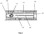
- the piston member 113 comprises a passageway 115 extending from the first end portion 131 of the piston member 113 to the second end portion 133 of the piston member 113.
- the valve member 117 is a ball 117 disposed within the passageway 115 of the piston member 113 and is moveable or freely moveable therein. This provides a simpler valve arrangement to the existing single coil pump by providing fewer components and avoiding the need for a helical spring to control the movement of the valve member.
- the valve member 117 of the present invention is simpler and more reliable as there are fewer components which may be damaged or fail.
- the first end portion 131 of the piston member 113 comprises a first obstruction 135 for preventing the valve member 117 from exiting the passageway 115.
- the first obstruction 135 is a tapering or narrowing section of the passageway 115.
- the valve member 117 cooperates with the first obstruction 135 to close the passageway 115 at the first end portion 131 to prevent the passage of fluid therethrough.
- the second end portion 133 comprises a second obstruction 137, 139 adapted to prevent the valve member 117 from exiting the passageway 115 while allowing the passage of fluid therethrough.
- the second obstruction 137, 139 comprises a stop member 139 in the form of an extending projection 139 and a mesh material 137.
- the extending projection 139 acts to limit the length of passageway 115 that the valve member 117 may move through.
- the extending projection 139 is constructed from a stiff material such as stainless steel or titanium, and may be in the form of a helix. In some arrangements, the extending projection 139 may separately or additionally act to "cup" the valve member 117 when the valve member 117 is not blocking the passageway 115. In these arrangements, the extending projection 139 acts to keep the valve member 117 centred and allow fluid flow around/past the valve member 117.
- the mesh material 137 is disposed towards the extreme end of the second end portion 133 and acts as an attachment point for the extending projection 139.
- the mesh material 137 may be disposed more proximate to the first end portion 131.
- the mesh material 137 acts to limit the length of the passageway through which the valve member 117 may move and therefore acts as a stop member.
- the extending projection 139 may not be included.
- piston member 113 may have a symmetric appearance such that both end portions 131, 133 of the piston member 113 comprise a first obstruction 135 in the form of a tapering or narrowing section of the passageway 115.
- valve member 117 moves within the passageway 115 to selectively close the passageway 115.
- the piston member 113 is being pulled towards the outlet 105.
- the valve member 117 cooperates with the first obstruction 135 to close the passageway 115. In this way, fluid cannot pass through the passageway 115 in the direction towards the inlet 103 of the conduit 101 and as a consequence fluid is pumped through the outlet 105 due to the movement of the piston member 113 towards the outlet 105.
- the valve member 117 is magnetic or magnetisable.
- the magnetic or magnetisable valve member 117 is able to move with the pump member 113 under the influence of the first and/or second magnetic field.
- the magnetic or magnetisable valve member 117 is pulled away from one end portion of the piston member 113 towards the other end portion of the piston member 113 such that the valve member performs an automatic or self-sealing function.
- the movement of the magnetic or magnetisable valve member 117 within the conduit 101 may cause or enhance the movement of the piston member 113 within the conduit 101 under the influence of the first and/or second magnetic field.
- valve member 117 is magnetic or magnetisable and the piston member 113 comprises a non-magnetic or non-magnetisable material.
- valve member 117 is magnetic or magnetisable and the piston member is magnetic or magnetisable.
- the magnetic or magnetisable material used for the valve member 117 may comprise a soft magnetic stainless steel and/or may comprise neodymium.
- valve member 117 is formed from a non-magnetic material.
- a non-magnetic material useable for the valve member 117 is zirconium.
- the first magnetic field generating unit 109 and the second magnetic field generating unit 111 are spaced apart from one another by a relatively short distance such that they are proximate to one another.
- the distance between the first and second magnetic field generating units 109, 111 is less than the length of the piston member 113.
- a large (or larger) magnetic flux is generated towards the facing end regions 141, 143 of the first and second magnetic field generating units 109, 111.
- the first and second magnetic field generating units 109, 111 cooperate to generate this large (or larger) magnetic flux and thus the piston member 113 experiences a greater driving force.
- the first magnetic field generating unit 109 and the second magnetic field generating unit 111 are sufficiently proximate to one another that a region of large magnetic flux is generated between the first and second magnetic field generating units 109, 111.
- the first magnetic field generating unit 109 and second magnetic field generating unit 111 are sufficiently proximate to one another that in the equilibrium position, the end portions 131, 133 of the piston member 113 are proximate to the facing end portions 141, 143 of the first and second magnetic field generating units 109,111. This means that in the equilibrium position the piston member 113 will experience the maximum magnetic flux.
- the piston member 113 is therefore in the optimum position for maximum deflection and as a result the piston member 113 experiences a greater driving force.
- the electromagnetic pump 100 includes the same elements as the electromagnetic pump 100 shown in Figures 1-5 except for the obstruction element 139. Instead, the mesh material 137 acts as the obstruction element by itself.
- the first magnetic field generating unit 109 and the second magnetic field generating unit 111 are further spaced apart from one another than in the arrangement shown in Figures 1-5 .
- the distance between the first and second magnetic field generating units 109, 111 is approximately the same as the length of the piston member 113.
- the magnetic flux generated between the first and second magnetic field generating units 109, 111 will be less than embodiment of Figure 1 .
- the most magnetic flux will be generated when the ends 131, 133 of the piston member 113 are close to the facing edge portions 141, 143 of the first and second magnetic field generating units 109, 111.
- the first magnetic field generating unit 109 comprises a first coil 109.
- the second magnetic field generating unit 111 comprises a second coil 111.
- the first coil 109 and the second coil 111 are driven by separate power supplies.
- the first coil 109 has windings disposed in a first winding direction and the second coil 111 has windings disposed in a second winding direction opposite or substantially opposite to the first winding direction.
- the first and second coil 109, 111 can be driven by the same power supply.
- the first coil 109 and/or the second coil 111 surround the circumference of the conduit 101.
- the first and/or second coils 109, 111 are constructed from copper.
- the conduit 101 is constructed from a non-magnetic material.
- An example of the non-magnetic material is non-magnetic stainless steel.
- the electromagnetic pump 100 comprises an outer housing 151 that surrounds the conduit 101.
- the outer housing 151 may be constructed from a non-magnetic material.
- An example of the non-magnetic material is non-magnetic stainless steel.
- the outer housing 151 may be constructed from a biocompatible material.
- the electromagnetic pump 100 has a volume of between 1 cm 3 and 21 cm 3 .
- the electromagnetic pump 100 is able operate over a range of frequencies.
- the frequencies range from 1 Hz to 120 Hz in some example arrangements.
- the electromagnetic pump 100 is able operate over a range of input powers.
- the input powers range from 0.1 Wto 10 W in some example arrangements.
- the electromagnetic pump 100 is suitable for use as an electromagnetic micropump 100.
- Micropumps have pumping characteristics which enable them to be used in microfluidics. Microfludics is a diverse application that is used in a wide array of industries, including the microelectronics, aerospace, telecommunications, biomedical and pharmaceutical sectors. A critical issue that is holding back development of the microfluidic industry is the lack of efficient, reliable pumping. Known existing micropumps have time to failures of approximately 5000 to 10000 hours, irrespective of the driving technology. This level of reliability is insufficient for most micropump applications especially those related to the biomedical and pharmaceutical sectors.
- the electromagnetic micropump 100 of the present invention has overcome the problem of low reliability present in existing micropump technologies. This is due to the advantageous structure of the electromagnetic micropump 100 of the present invention, for example due to the limited number of moving parts; the absence of diaphragm members; and the efficient use of two magnetic field generating units 109, 111 to drive the piston member 113 within the conduit 101. Further, the electromagnetic micropump 100 is self-priming and can operate at high temperatures (e.g. greater than 100 degrees Centigrade). Here, self-priming means that the electromagnetic micropump 100 can pump air as well as liquid, and thus can draw the liquid into itself when not full with fluid. Some existing known micropumps need to have liquid pulled (or pushed) through them in order to work because they cannot pump air. This self-priming property is also applicable to the general electromagnetic pump 100 of the present invention.
- the electromagnetic micropump 100 provides high pressure-flow characteristics of approximately 50ml/min at 35kPa pressure, and in another example is able to prove high pressure-flow characteristics of approximately 200 ml/min at 50kPa at a low power consumption of approximately less than 1W and a small physical size of between 1 and 4 cm 3 .
- the electromagnetic micropump 100 is able to achieve high flow rates of up to 98ml/min at 1W input power. In one example, this high flow rate is more than is required for most existing biomedical applications.
- the electromagnetic micropump 100 is able to operate in a closed loop -which is not available in existing micropumps which operate using solenoids or diaphragms. These existing pumps can change volume which is generally acceptable in an open loop system, but in a closed loop system it is generally not acceptable as there is nowhere for the fluid to go.
- the closed loop operating property is also applicable to the general electromagnetic pump 100 of the present invention.
- FIGS 8(a)-8(d) there are shown the pumping characteristics according to one example electromagnetic micropump 100. These pumping characteristics are just to highlight the advantageous properties that can be achieved by the electromagnetic pump 100 of the present invention. It will be appreciated that different pumping characteristics will be achieved based on, for example, the volume of the electromagnetic pump 100.
- FIG. 8(a) it can be seen how the flow rate of the example electromagnetic micropump 100 varies as a function of the driving frequency at 1W input power.
- the maximum flow rate is achieved at approximately 15Hz, and an upper limiting frequency of ⁇ 120 Hz exists before significant reduction occurs.
- the lower drop off is due to the pump length and magnetic springs 119, 121, and the upper limits is due to the maximum switching capacity of the valve member 117.
- FIG. 8(c) it can be seen how the pressure-flow characteristics of the example electromagnetic micropump 100 vary over a range of input powers up to 2W.
- the pressure-flow characteristics are consistent in form over the range of input powers.
- a maximum flow rate of 48 ml/min and a pressure of 30 kPa is achieved; this increases (nonlinearly) with power, with 86 ml/min and 37 kPa developed at 2 W.
- the conduit 101 is approximately 40 mm long and has an internal diameter of 6.35mm and an external diameter of 12.5mm.
- the first windings of the first coil 109 and the second coil 111 have a diameter of approximately 0.12 mmm.
- the internal passageway 115 of the piston member 113 has a diameter of approximately 3.12 mm.
- the present disclosure is not limited to any particular dimensions of components.
- FIG. 9 there is shown an example operation of the electromagnetic pump 100 to pump fluid through the conduit 101.
- the first magnetic field generating unit 109 is driven to generate a first magnetic field, the first magnetic field having a first component with a first direction in the conduit 101.
- the second magnetic field generating unit 111 is driven to generate a second magnetic field, the second magnetic field having a second component with a second direction in the conduit 101, the second direction being substantially opposite to the first direction.
- the first and/or second magnetic fields generated at S201 and S202 move the piston member 113 within the conduit 101 to pump fluid through the conduit 101.
- S201 and S202 may be performed simultaneously such that the first and second magnetic field generating units 109, 111 are simultaneously driven to generate the first and second magnetic fields.
- the first and second magnetic field generating units 109, 111 may be driven under one or more alternating power cycles to periodically reverse the direction of the magnetic fields generated by the first and second magnetic field generating units 109, 111.
- the first and second magnetic field generating units 109, 111 direct the first component of the first magnetic field and the second component of the second magnetic field towards one another.
- the first and second magnetic field generating units 109, 111 direct the first component of the first magnetic field and the second component of the second magnetic field away from one another.
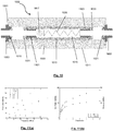
- the electromagnetic pump 1000 operates in the same way as the electromagnetic pumps of the present invention described above.
- the electromagnetic pump 1000 comprises a titanium conduit/housing 101.
- the first and second magnetic field generating units 1009, 1011 are in the form of copper coils.
- the piston member 1013 is constructed from neodymium.
- At the end portions of the piston member 1013 there are titanium fitting members 1101, 1103 with neodymium end portions 1031, 1033 attached thereto.
- the piston member 1013 further comprises another obstruction member 1039 in the form of a helix constructed from titanium to reduce the distance by which the ball 1017 can move within the passageway 1015.
- the inlet 1003 and the outlet 1005 of the conduit 1001 comprise titanium fittings and have neodymium magnetic members 1019, 1021 which act to bias the piston member 1013 away from the ends of the conduit 1001.
- the electromagnetic pump 1000 is a micropump 1000.
- the length of the electromagnetic pump 1000 is 19 mm.
- the internal diameter of the conduit 1001 is 5mm.
- the separation between the coils 1009, 1011 is 1mm.
- the coils are 8mm in length.
- the passageway 1015 has an internal diameter of 3.17mm.
- the titanium fitting members 1101, 1103 have an internal diameter of 2mm.
- the ball 1017 has a diameter of 2.3mm. There is a 1mm separation between the ends of the coils 1009, 1011 and the ends of the conduit 1001.
- FIGS 11(a)-11(b) there are shown the pumping characteristics according to one example electromagnetic micropump 1000. These pumping characteristics are just to highlight the advantageous properties that can be achieved by the electromagnetic pump 1000 of the present invention. It will be appreciated that different pumping characteristics will be achieved based on, for example, the volume of the electromagnetic pump 1000.
Landscapes
- Engineering & Computer Science (AREA)
- Mechanical Engineering (AREA)
- General Engineering & Computer Science (AREA)
- Physics & Mathematics (AREA)
- Fluid Mechanics (AREA)
- Electromagnetic Pumps, Or The Like (AREA)
Claims (13)
- Elektromagnetische Pumpe (100), die umfasst:eine Rohrleitung (101), die einen Einlass (103) und einen Auslass (105) umfasst;eine erste Magnetfelderzeugungseinheit (109) zum Erzeugen eines ersten Magnetfelds mit einer ersten Komponente mit einer ersten Richtung in der Rohrleitung (101) ;eine zweite Magnetfelderzeugungseinheit (111) zum Erzeugen eines zweiten Magnetfelds mit einer zweiten Komponente mit einer zweiten Richtung in der Rohrleitung (101), wobei die zweite Richtung der ersten Richtung im Wesentlichen entgegengesetzt ist;ein in der Rohrleitung angeordnetes Kolbenelement (113), wobei das Kolbenelement (113) in der Rohrleitung (101) unter der Wirkung der ersten und/oder zweiten Magnetfelder beweglich ist, um von dem Einlass (103) der Rohrleitung (101) aufgenommenes Fluid zu dem Auslass (105) der Rohrleitung (101) zu pumpen,dadurch gekennzeichnet, dassdie elektromagnetische Pumpe (100) ferner ein oder mehrere Vorspannungsmittel zum Drücken des Kolbenelements (113) weg von einem oder beiden des Einlasses (103) und des Auslasses (105) der Rohrleitung (101) und in eine Gleichgewichtsposition zwischen der ersten Magnetfelderzeugungseinheit (109) und der zweiten Magnetfelderzeugungseinheit (111) umfasst, wobei das Vorspannungsmittel ein oder mehrere magnetische Elemente (119, 121) umfasst,wobei die erste Magnetfelderzeugungseinheit (109) und die zweite Magnetfelderzeugungseinheit (111) hinreichend nahe zueinander gelegen sind, dass in der Gleichgewichtsposition die Endabschnitte des Kolbenelements (113) nahe zu den zugewandten Endabschnitten der ersten und zweiten Magnetfelderzeugungseinheiten (109; 111) gelegen sind.
- Elektromagnetische Pumpe (100) nach Anspruch 1, wobei die ersten und zweiten Magnetfelderzeugungseinheiten (109, 111) ausgelegt sind, gleichzeitig zum Erzeugen der ersten und zweiten Magnetfelder angetrieben zu werden.
- Elektromagnetische Pumpe (100) nach Anspruch 1 oder Anspruch 2, wobei die ersten und zweiten Magnetfelderzeugungseinheiten (109, 111) ausgelegt sind, unter einem oder mehreren Wechselleistungszyklen angetrieben zu werden, um die Richtung der durch die ersten und zweiten Magnetfelderzeugungseinheiten (109, 111) erzeugten Magnetfelder periodisch umzukehren.
- Elektromagnetische Pumpe (100) nach Anspruch 3, wobei während eines ersten Abschnitts des einen oder der mehreren Wechselleistungszyklen die ersten und zweiten Magnetfelderzeugungseinheiten (109, 111) ausgelegt sind, die erste Komponente des ersten Magnetfelds und die zweite Komponente des zweiten Magnetfelds zueinander hin zu lenken, und/oder während eines zweiten Abschnitts des einen oder der mehreren Wechselleistungszyklen die ersten und zweiten Magnetfelderzeugungseinheiten (109, 111) ausgelegt sind, die erste Komponente des ersten Magnetfelds und die zweite Komponente des zweiten Magnetfelds voneinander weg zu lenken.
- Elektromagnetische Pumpe (100) nach einem der vorhergehenden Ansprüche, ferner umfassend ein Ventilelement (117), das ausgelegt ist, die Strömung von Fluid von dem Einlass (103) der Rohrleitung (101) zu dem Auslass (105) der Rohrleitung (101) zu erlauben und die Strömung von Fluid von dem Auslass (105) der Rohrleitung (101) zu dem Einlass (103) der Rohrleitung (101) zu drosseln.
- Elektromagnetische Pumpe (100) nach Anspruch 5, wobei das Ventilelement (117) ausgelegt ist, sich mit dem Kolbenelement (113) durch die Rohrleitung (101) zu bewegen.
- Elektromagnetische Pumpe (100) nach Anspruch 5 oder 6, wobei das Kolbenelement (113) einen sich dadurch erstreckenden Durchgang (115) umfasst, und das Ventilelement (117) zumindest teilweise in dem Durchgang (115) des Kolbenelements (113) angeordnet ist.
- Elektromagnetische Pumpe (100) nach einem der vorhergehenden Ansprüche, wobei die erste Magnetfelderzeugungseinheit (109) und die zweite Magnetfelderzeugungseinheit (111) derart voneinander beabstandet sind, dass ein erster Bereich der Rohrleitung (101) zwischen den ersten und zweiten Magnetfelderzeugungseinheiten (109, 111) angeordnet ist.
- Elektromagnetische Pumpe (100) nach einem der vorhergehenden Ansprüche, wobei die erste Magnetfelderzeugungseinheit (109) eine erste Spule (109) umfasst und die zweite Magnetfelderzeugungseinheit (111) eine zweite Spule (111) umfasst.
- Elektromagnetische Pumpe (100) nach Anspruch 9, wobei die erste Spule (109) in einer ersten Wicklungsrichtung angeordnete Wicklungen aufweist und die zweite Spule (111) in einer der ersten Wicklungsrichtung entgegengesetzten zweiten Wicklungsrichtung angeordnete Wicklungen aufweist.
- Elektromagnetische Pumpe (100) nach Anspruch 9 oder Anspruch 10, wobei die erste Spule (109) und/oder die zweite Spule (111) die Rohrleitung (101) umgeben.
- Elektromagnetische Pumpe (100) nach einem der vorhergehenden Ansprüche, wobei das Kolbenelement (113) ein magnetisches oder magnetisierbares Element umfasst.
- Verfahren zum Pumpen von Fluid durch eine Rohrleitung mit einem darin angeordneten Kolbenelement, wobei das Verfahren umfasst:Antreiben einer ersten Magnetfelderzeugungseinheit (109) zum Erzeugen eines ersten Magnetfelds, wobei das erste Magnetfeld eine erste Komponente mit einer ersten Richtung in der Rohrleitung aufweist (S201);Antreiben einer zweiten Magnetfelderzeugungseinheit (111) zum Erzeugen eines zweiten Magnetfelds, wobei das zweite Magnetfeld eine zweite Komponente mit einer zweiten Richtung in der Rohrleitung aufweist, wobei die zweite Richtung der ersten Richtung im Wesentlichen entgegengesetzt ist (S202);wobei die ersten und/oder zweiten Magnetfelder das Kolbenelement in der Rohrleitung bewegen, um Fluid durch die Rohrleitung zu pumpen (S201, S202),dadurch gekennzeichnet, dassdas Verfahren ferner Drücken des Kolbenelements (113) weg von einem oder beiden des Einlasses (103) und des Auslasses (105) der Rohrleitung (101) und in eine Gleichgewichtsposition zwischen der ersten Magnetfelderzeugungseinheit (109) und der zweiten Magnetfelderzeugungseinheit (111) umfasst, wobei das Vorspannungsmittel ein oder mehrere magnetische Elemente (119, 121) umfasst,wobei die erste Magnetfelderzeugungseinheit (109) und die zweite Magnetfelderzeugungseinheit (111) hinreichend nahe zueinander gelegen sind, dass in der Gleichgewichtsposition die Endabschnitte des Kolbenelements (113) nahe zu den zugewandten Endabschnitten der ersten und zweiten Magnetfelderzeugungseinheiten (109; 111) gelegen sind.
Applications Claiming Priority (2)
| Application Number | Priority Date | Filing Date | Title |
|---|---|---|---|
| GB1705431.3A GB2561195A (en) | 2017-04-04 | 2017-04-04 | Electromagnetic pump |
| PCT/EP2018/058172 WO2018185005A1 (en) | 2017-04-04 | 2018-03-29 | Electromagnetic pump |
Publications (2)
| Publication Number | Publication Date |
|---|---|
| EP3607201A1 EP3607201A1 (de) | 2020-02-12 |
| EP3607201B1 true EP3607201B1 (de) | 2021-03-17 |
Family
ID=58682851
Family Applications (1)
| Application Number | Title | Priority Date | Filing Date |
|---|---|---|---|
| EP18713956.3A Active EP3607201B1 (de) | 2017-04-04 | 2018-03-29 | Elektromagnetische pumpe |
Country Status (4)
| Country | Link |
|---|---|
| US (1) | US11408405B2 (de) |
| EP (1) | EP3607201B1 (de) |
| GB (1) | GB2561195A (de) |
| WO (1) | WO2018185005A1 (de) |
Cited By (1)
| Publication number | Priority date | Publication date | Assignee | Title |
|---|---|---|---|---|
| WO2025243055A1 (en) * | 2024-05-24 | 2025-11-27 | Synchrostor Limited | In-piston valve assembly |
Families Citing this family (4)
| Publication number | Priority date | Publication date | Assignee | Title |
|---|---|---|---|---|
| GB2561195A (en) | 2017-04-04 | 2018-10-10 | Univ Limerick | Electromagnetic pump |
| GB202002485D0 (en) * | 2020-02-21 | 2020-04-08 | Univ Limerick | Apparatus for use in measuring a property of a fluid and method |
| CN114531007B (zh) * | 2022-03-03 | 2023-09-22 | 上海交通大学 | 金属熔体电磁泵 |
| CN114810543B (zh) * | 2022-06-07 | 2022-12-06 | 广东罗曼智能科技股份有限公司 | 一种磁动力水泵 |
Family Cites Families (17)
| Publication number | Priority date | Publication date | Assignee | Title |
|---|---|---|---|---|
| US2761392A (en) * | 1953-10-08 | 1956-09-04 | Bendix Aviat Corp | Electromagnetic pump |
| US3384021A (en) * | 1966-08-29 | 1968-05-21 | Little Inc A | Electromagnetic reciprocating fluid pump |
| US3836289A (en) * | 1972-09-06 | 1974-09-17 | E Wolford | Magnetic pump |
| DE3033684A1 (de) * | 1980-09-08 | 1982-04-29 | Robert Bosch Gmbh, 7000 Stuttgart | Kolbenpumpe mit elektromagnetischem antrieb |
| DE3132897A1 (de) * | 1981-08-20 | 1983-03-03 | Robert Bosch Gmbh, 7000 Stuttgart | Foerderpumpe |
| KR940015296A (ko) * | 1992-12-15 | 1994-07-20 | 김광호 | 자기 유체 펌프 |
| DE69311525T2 (de) * | 1993-01-07 | 1997-10-02 | Tdk Corp | Elektromagnetpumpe mit beweglichem Magnetkolben |
| JPH08210248A (ja) * | 1994-10-31 | 1996-08-20 | Harry Ono | 複式ピストン・ポンプ |
| US5713728A (en) * | 1996-01-19 | 1998-02-03 | Salamey; Laurence R. | Electromagnetic pump with plastic covered piston |
| NL1018567C2 (nl) * | 2001-07-17 | 2003-01-20 | Frans Lodewijk Rijnberg | Magnetisch aangedreven pomp. |
| US6851938B2 (en) * | 2001-08-28 | 2005-02-08 | Vanderbilt University | Magnetic pumping system |
| TWI265239B (en) * | 2003-09-22 | 2006-11-01 | Delta Electronics Inc | Pump |
| US9695806B2 (en) * | 2009-07-22 | 2017-07-04 | Vbox, Incorporated | Method of controlling gaseous fluid pump |
| FR2960268B1 (fr) * | 2010-05-21 | 2013-04-05 | Sauermann Ind Sa | Pompe electromagnetique a piston oscillant |
| US8449274B1 (en) * | 2011-03-10 | 2013-05-28 | Sielc Technologies Corporation | Magnetic reciprocating pump |
| US9341182B2 (en) * | 2012-04-11 | 2016-05-17 | Gotec Sa | Electromagnetic pump |
| GB2561195A (en) | 2017-04-04 | 2018-10-10 | Univ Limerick | Electromagnetic pump |
-
2017
- 2017-04-04 GB GB1705431.3A patent/GB2561195A/en not_active Withdrawn
-
2018
- 2018-03-29 EP EP18713956.3A patent/EP3607201B1/de active Active
- 2018-03-29 WO PCT/EP2018/058172 patent/WO2018185005A1/en not_active Ceased
- 2018-03-29 US US16/487,989 patent/US11408405B2/en active Active
Non-Patent Citations (1)
| Title |
|---|
| None * |
Cited By (1)
| Publication number | Priority date | Publication date | Assignee | Title |
|---|---|---|---|---|
| WO2025243055A1 (en) * | 2024-05-24 | 2025-11-27 | Synchrostor Limited | In-piston valve assembly |
Also Published As
| Publication number | Publication date |
|---|---|
| WO2018185005A1 (en) | 2018-10-11 |
| GB2561195A (en) | 2018-10-10 |
| EP3607201A1 (de) | 2020-02-12 |
| US11408405B2 (en) | 2022-08-09 |
| US20200025188A1 (en) | 2020-01-23 |
| GB201705431D0 (en) | 2017-05-17 |
Similar Documents
| Publication | Publication Date | Title |
|---|---|---|
| EP3607201B1 (de) | Elektromagnetische pumpe | |
| US9028227B2 (en) | Electromagnetic pump with oscillating piston | |
| EP2427655B1 (de) | Membranpumpe | |
| US20120275929A1 (en) | Ferrofluid control and sample collection for microfluidic application | |
| SE529284C2 (sv) | Membranpump | |
| US8622720B2 (en) | Reciprocating fluid pumps including magnets and related methods | |
| US20110091340A1 (en) | Reciprocating pump and check valve | |
| US20050053490A1 (en) | Oscillating-piston drive for a vacuum pump and an operating method for said drive | |
| EP2993346A1 (de) | Magnetische vorrichtung für schwingkolbenpumpen | |
| JP7221236B2 (ja) | 磁石を含む往復流体ポンプ、ならびにこれに関連するアセンブリ、システム、および方法 | |
| US20150144821A1 (en) | Rear electromagnet for vibrating pump and valves | |
| TW200641251A (en) | A pump device with a piston-like object driven by magnetic force | |
| CN106662085B (zh) | 线性致动器及用于操作这样的线性致动器的方法 | |
| NL2028155B1 (nl) | Vloeistofverplaatsingsinrichting alsmede een keerklep | |
| JP5329183B2 (ja) | マイクロポンプ | |
| CN119393312A (zh) | 一种重力泵水装置 | |
| JP2005114105A (ja) | 電磁弁装置 | |
| JP2006329007A (ja) | 電流制御往復式流体圧送ユニット | |
| JP4906092B2 (ja) | 定流量小型ポンプ | |
| JP2009121437A (ja) | 流体貯蔵槽 | |
| CN104995408A (zh) | 具有磁流体动力学驱动器的膜片泵 | |
| Ando et al. | A novel non-invasive implementation of pumping mechanism in pre-existing capillary | |
| JP2005054637A (ja) | 電磁ポンプの固定子 | |
| JP2005315093A (ja) | 電磁式容積型ポンプ | |
| UA80836C2 (en) | Electromagnetic valve |
Legal Events
| Date | Code | Title | Description |
|---|---|---|---|
| STAA | Information on the status of an ep patent application or granted ep patent |
Free format text: STATUS: UNKNOWN |
|
| STAA | Information on the status of an ep patent application or granted ep patent |
Free format text: STATUS: THE INTERNATIONAL PUBLICATION HAS BEEN MADE |
|
| PUAI | Public reference made under article 153(3) epc to a published international application that has entered the european phase |
Free format text: ORIGINAL CODE: 0009012 |
|
| STAA | Information on the status of an ep patent application or granted ep patent |
Free format text: STATUS: REQUEST FOR EXAMINATION WAS MADE |
|
| 17P | Request for examination filed |
Effective date: 20190820 |
|
| AK | Designated contracting states |
Kind code of ref document: A1 Designated state(s): AL AT BE BG CH CY CZ DE DK EE ES FI FR GB GR HR HU IE IS IT LI LT LU LV MC MK MT NL NO PL PT RO RS SE SI SK SM TR |
|
| AX | Request for extension of the european patent |
Extension state: BA ME |
|
| DAV | Request for validation of the european patent (deleted) | ||
| DAX | Request for extension of the european patent (deleted) | ||
| STAA | Information on the status of an ep patent application or granted ep patent |
Free format text: STATUS: EXAMINATION IS IN PROGRESS |
|
| 17Q | First examination report despatched |
Effective date: 20200806 |
|
| GRAP | Despatch of communication of intention to grant a patent |
Free format text: ORIGINAL CODE: EPIDOSNIGR1 |
|
| STAA | Information on the status of an ep patent application or granted ep patent |
Free format text: STATUS: GRANT OF PATENT IS INTENDED |
|
| INTG | Intention to grant announced |
Effective date: 20210115 |
|
| GRAS | Grant fee paid |
Free format text: ORIGINAL CODE: EPIDOSNIGR3 |
|
| GRAA | (expected) grant |
Free format text: ORIGINAL CODE: 0009210 |
|
| STAA | Information on the status of an ep patent application or granted ep patent |
Free format text: STATUS: THE PATENT HAS BEEN GRANTED |
|
| AK | Designated contracting states |
Kind code of ref document: B1 Designated state(s): AL AT BE BG CH CY CZ DE DK EE ES FI FR GB GR HR HU IE IS IT LI LT LU LV MC MK MT NL NO PL PT RO RS SE SI SK SM TR |
|
| REG | Reference to a national code |
Ref country code: GB Ref legal event code: FG4D |
|
| REG | Reference to a national code |
Ref country code: CH Ref legal event code: EP |
|
| REG | Reference to a national code |
Ref country code: DE Ref legal event code: R096 Ref document number: 602018014060 Country of ref document: DE |
|
| REG | Reference to a national code |
Ref country code: IE Ref legal event code: FG4D |
|
| REG | Reference to a national code |
Ref country code: AT Ref legal event code: REF Ref document number: 1372479 Country of ref document: AT Kind code of ref document: T Effective date: 20210415 |
|
| REG | Reference to a national code |
Ref country code: LT Ref legal event code: MG9D |
|
| PG25 | Lapsed in a contracting state [announced via postgrant information from national office to epo] |
Ref country code: NO Free format text: LAPSE BECAUSE OF FAILURE TO SUBMIT A TRANSLATION OF THE DESCRIPTION OR TO PAY THE FEE WITHIN THE PRESCRIBED TIME-LIMIT Effective date: 20210617 Ref country code: GR Free format text: LAPSE BECAUSE OF FAILURE TO SUBMIT A TRANSLATION OF THE DESCRIPTION OR TO PAY THE FEE WITHIN THE PRESCRIBED TIME-LIMIT Effective date: 20210618 Ref country code: FI Free format text: LAPSE BECAUSE OF FAILURE TO SUBMIT A TRANSLATION OF THE DESCRIPTION OR TO PAY THE FEE WITHIN THE PRESCRIBED TIME-LIMIT Effective date: 20210317 Ref country code: HR Free format text: LAPSE BECAUSE OF FAILURE TO SUBMIT A TRANSLATION OF THE DESCRIPTION OR TO PAY THE FEE WITHIN THE PRESCRIBED TIME-LIMIT Effective date: 20210317 Ref country code: BG Free format text: LAPSE BECAUSE OF FAILURE TO SUBMIT A TRANSLATION OF THE DESCRIPTION OR TO PAY THE FEE WITHIN THE PRESCRIBED TIME-LIMIT Effective date: 20210617 |
|
| REG | Reference to a national code |
Ref country code: AT Ref legal event code: MK05 Ref document number: 1372479 Country of ref document: AT Kind code of ref document: T Effective date: 20210317 |
|
| REG | Reference to a national code |
Ref country code: NL Ref legal event code: MP Effective date: 20210317 |
|
| PG25 | Lapsed in a contracting state [announced via postgrant information from national office to epo] |
Ref country code: RS Free format text: LAPSE BECAUSE OF FAILURE TO SUBMIT A TRANSLATION OF THE DESCRIPTION OR TO PAY THE FEE WITHIN THE PRESCRIBED TIME-LIMIT Effective date: 20210317 Ref country code: LV Free format text: LAPSE BECAUSE OF FAILURE TO SUBMIT A TRANSLATION OF THE DESCRIPTION OR TO PAY THE FEE WITHIN THE PRESCRIBED TIME-LIMIT Effective date: 20210317 Ref country code: SE Free format text: LAPSE BECAUSE OF FAILURE TO SUBMIT A TRANSLATION OF THE DESCRIPTION OR TO PAY THE FEE WITHIN THE PRESCRIBED TIME-LIMIT Effective date: 20210317 |
|
| PG25 | Lapsed in a contracting state [announced via postgrant information from national office to epo] |
Ref country code: NL Free format text: LAPSE BECAUSE OF FAILURE TO SUBMIT A TRANSLATION OF THE DESCRIPTION OR TO PAY THE FEE WITHIN THE PRESCRIBED TIME-LIMIT Effective date: 20210317 |
|
| PG25 | Lapsed in a contracting state [announced via postgrant information from national office to epo] |
Ref country code: CZ Free format text: LAPSE BECAUSE OF FAILURE TO SUBMIT A TRANSLATION OF THE DESCRIPTION OR TO PAY THE FEE WITHIN THE PRESCRIBED TIME-LIMIT Effective date: 20210317 Ref country code: EE Free format text: LAPSE BECAUSE OF FAILURE TO SUBMIT A TRANSLATION OF THE DESCRIPTION OR TO PAY THE FEE WITHIN THE PRESCRIBED TIME-LIMIT Effective date: 20210317 Ref country code: LT Free format text: LAPSE BECAUSE OF FAILURE TO SUBMIT A TRANSLATION OF THE DESCRIPTION OR TO PAY THE FEE WITHIN THE PRESCRIBED TIME-LIMIT Effective date: 20210317 Ref country code: SM Free format text: LAPSE BECAUSE OF FAILURE TO SUBMIT A TRANSLATION OF THE DESCRIPTION OR TO PAY THE FEE WITHIN THE PRESCRIBED TIME-LIMIT Effective date: 20210317 Ref country code: AT Free format text: LAPSE BECAUSE OF FAILURE TO SUBMIT A TRANSLATION OF THE DESCRIPTION OR TO PAY THE FEE WITHIN THE PRESCRIBED TIME-LIMIT Effective date: 20210317 |
|
| REG | Reference to a national code |
Ref country code: CH Ref legal event code: PL |
|
| PG25 | Lapsed in a contracting state [announced via postgrant information from national office to epo] |
Ref country code: IS Free format text: LAPSE BECAUSE OF FAILURE TO SUBMIT A TRANSLATION OF THE DESCRIPTION OR TO PAY THE FEE WITHIN THE PRESCRIBED TIME-LIMIT Effective date: 20210717 Ref country code: PL Free format text: LAPSE BECAUSE OF FAILURE TO SUBMIT A TRANSLATION OF THE DESCRIPTION OR TO PAY THE FEE WITHIN THE PRESCRIBED TIME-LIMIT Effective date: 20210317 Ref country code: RO Free format text: LAPSE BECAUSE OF FAILURE TO SUBMIT A TRANSLATION OF THE DESCRIPTION OR TO PAY THE FEE WITHIN THE PRESCRIBED TIME-LIMIT Effective date: 20210317 Ref country code: PT Free format text: LAPSE BECAUSE OF FAILURE TO SUBMIT A TRANSLATION OF THE DESCRIPTION OR TO PAY THE FEE WITHIN THE PRESCRIBED TIME-LIMIT Effective date: 20210719 Ref country code: SK Free format text: LAPSE BECAUSE OF FAILURE TO SUBMIT A TRANSLATION OF THE DESCRIPTION OR TO PAY THE FEE WITHIN THE PRESCRIBED TIME-LIMIT Effective date: 20210317 |
|
| REG | Reference to a national code |
Ref country code: BE Ref legal event code: MM Effective date: 20210331 |
|
| REG | Reference to a national code |
Ref country code: DE Ref legal event code: R097 Ref document number: 602018014060 Country of ref document: DE |
|
| PLBE | No opposition filed within time limit |
Free format text: ORIGINAL CODE: 0009261 |
|
| STAA | Information on the status of an ep patent application or granted ep patent |
Free format text: STATUS: NO OPPOSITION FILED WITHIN TIME LIMIT |
|
| PG25 | Lapsed in a contracting state [announced via postgrant information from national office to epo] |
Ref country code: DK Free format text: LAPSE BECAUSE OF FAILURE TO SUBMIT A TRANSLATION OF THE DESCRIPTION OR TO PAY THE FEE WITHIN THE PRESCRIBED TIME-LIMIT Effective date: 20210317 Ref country code: CH Free format text: LAPSE BECAUSE OF NON-PAYMENT OF DUE FEES Effective date: 20210331 Ref country code: AL Free format text: LAPSE BECAUSE OF FAILURE TO SUBMIT A TRANSLATION OF THE DESCRIPTION OR TO PAY THE FEE WITHIN THE PRESCRIBED TIME-LIMIT Effective date: 20210317 Ref country code: MC Free format text: LAPSE BECAUSE OF FAILURE TO SUBMIT A TRANSLATION OF THE DESCRIPTION OR TO PAY THE FEE WITHIN THE PRESCRIBED TIME-LIMIT Effective date: 20210317 Ref country code: IE Free format text: LAPSE BECAUSE OF NON-PAYMENT OF DUE FEES Effective date: 20210329 Ref country code: LI Free format text: LAPSE BECAUSE OF NON-PAYMENT OF DUE FEES Effective date: 20210331 Ref country code: LU Free format text: LAPSE BECAUSE OF NON-PAYMENT OF DUE FEES Effective date: 20210329 Ref country code: ES Free format text: LAPSE BECAUSE OF FAILURE TO SUBMIT A TRANSLATION OF THE DESCRIPTION OR TO PAY THE FEE WITHIN THE PRESCRIBED TIME-LIMIT Effective date: 20210317 |
|
| 26N | No opposition filed |
Effective date: 20211220 |
|
| PG25 | Lapsed in a contracting state [announced via postgrant information from national office to epo] |
Ref country code: SI Free format text: LAPSE BECAUSE OF FAILURE TO SUBMIT A TRANSLATION OF THE DESCRIPTION OR TO PAY THE FEE WITHIN THE PRESCRIBED TIME-LIMIT Effective date: 20210317 |
|
| PG25 | Lapsed in a contracting state [announced via postgrant information from national office to epo] |
Ref country code: IT Free format text: LAPSE BECAUSE OF FAILURE TO SUBMIT A TRANSLATION OF THE DESCRIPTION OR TO PAY THE FEE WITHIN THE PRESCRIBED TIME-LIMIT Effective date: 20210317 |
|
| PG25 | Lapsed in a contracting state [announced via postgrant information from national office to epo] |
Ref country code: IS Free format text: LAPSE BECAUSE OF FAILURE TO SUBMIT A TRANSLATION OF THE DESCRIPTION OR TO PAY THE FEE WITHIN THE PRESCRIBED TIME-LIMIT Effective date: 20210717 |
|
| PG25 | Lapsed in a contracting state [announced via postgrant information from national office to epo] |
Ref country code: BE Free format text: LAPSE BECAUSE OF NON-PAYMENT OF DUE FEES Effective date: 20210331 |
|
| PG25 | Lapsed in a contracting state [announced via postgrant information from national office to epo] |
Ref country code: CY Free format text: LAPSE BECAUSE OF FAILURE TO SUBMIT A TRANSLATION OF THE DESCRIPTION OR TO PAY THE FEE WITHIN THE PRESCRIBED TIME-LIMIT Effective date: 20210317 |
|
| PG25 | Lapsed in a contracting state [announced via postgrant information from national office to epo] |
Ref country code: HU Free format text: LAPSE BECAUSE OF FAILURE TO SUBMIT A TRANSLATION OF THE DESCRIPTION OR TO PAY THE FEE WITHIN THE PRESCRIBED TIME-LIMIT; INVALID AB INITIO Effective date: 20180329 |
|
| PG25 | Lapsed in a contracting state [announced via postgrant information from national office to epo] |
Ref country code: MK Free format text: LAPSE BECAUSE OF FAILURE TO SUBMIT A TRANSLATION OF THE DESCRIPTION OR TO PAY THE FEE WITHIN THE PRESCRIBED TIME-LIMIT Effective date: 20210317 |
|
| PG25 | Lapsed in a contracting state [announced via postgrant information from national office to epo] |
Ref country code: MT Free format text: LAPSE BECAUSE OF FAILURE TO SUBMIT A TRANSLATION OF THE DESCRIPTION OR TO PAY THE FEE WITHIN THE PRESCRIBED TIME-LIMIT Effective date: 20210317 |
|
| PG25 | Lapsed in a contracting state [announced via postgrant information from national office to epo] |
Ref country code: TR Free format text: LAPSE BECAUSE OF FAILURE TO SUBMIT A TRANSLATION OF THE DESCRIPTION OR TO PAY THE FEE WITHIN THE PRESCRIBED TIME-LIMIT Effective date: 20210317 |
|
| PGFP | Annual fee paid to national office [announced via postgrant information from national office to epo] |
Ref country code: GB Payment date: 20260313 Year of fee payment: 9 |
|
| PGFP | Annual fee paid to national office [announced via postgrant information from national office to epo] |
Ref country code: DE Payment date: 20260319 Year of fee payment: 9 |
|
| PGFP | Annual fee paid to national office [announced via postgrant information from national office to epo] |
Ref country code: FR Payment date: 20260320 Year of fee payment: 9 |