EP3606307B1 - Wärmeübertragungsvorrichtungen und verfahren zur übertragung von wärme - Google Patents
Wärmeübertragungsvorrichtungen und verfahren zur übertragung von wärme Download PDFInfo
- Publication number
- EP3606307B1 EP3606307B1 EP19180553.0A EP19180553A EP3606307B1 EP 3606307 B1 EP3606307 B1 EP 3606307B1 EP 19180553 A EP19180553 A EP 19180553A EP 3606307 B1 EP3606307 B1 EP 3606307B1
- Authority
- EP
- European Patent Office
- Prior art keywords
- disc
- heat transfer
- fluid
- transfer device
- pin
- Prior art date
- Legal status (The legal status is an assumption and is not a legal conclusion. Google has not performed a legal analysis and makes no representation as to the accuracy of the status listed.)
- Active
Links
Images




Classifications
-
- H—ELECTRICITY
- H05—ELECTRIC TECHNIQUES NOT OTHERWISE PROVIDED FOR
- H05K—PRINTED CIRCUITS; CASINGS OR CONSTRUCTIONAL DETAILS OF ELECTRIC APPARATUS; MANUFACTURE OF ASSEMBLAGES OF ELECTRICAL COMPONENTS
- H05K7/00—Constructional details common to different types of electric apparatus
- H05K7/20—Modifications to facilitate cooling, ventilating, or heating
- H05K7/20218—Modifications to facilitate cooling, ventilating, or heating using a liquid coolant without phase change in electronic enclosures
- H05K7/20254—Cold plates transferring heat from heat source to coolant
-
- H—ELECTRICITY
- H05—ELECTRIC TECHNIQUES NOT OTHERWISE PROVIDED FOR
- H05K—PRINTED CIRCUITS; CASINGS OR CONSTRUCTIONAL DETAILS OF ELECTRIC APPARATUS; MANUFACTURE OF ASSEMBLAGES OF ELECTRICAL COMPONENTS
- H05K7/00—Constructional details common to different types of electric apparatus
- H05K7/20—Modifications to facilitate cooling, ventilating, or heating
- H05K7/20218—Modifications to facilitate cooling, ventilating, or heating using a liquid coolant without phase change in electronic enclosures
-
- F—MECHANICAL ENGINEERING; LIGHTING; HEATING; WEAPONS; BLASTING
- F28—HEAT EXCHANGE IN GENERAL
- F28F—DETAILS OF HEAT-EXCHANGE AND HEAT-TRANSFER APPARATUS, OF GENERAL APPLICATION
- F28F13/00—Arrangements for modifying heat-transfer, e.g. increasing, decreasing
- F28F13/06—Arrangements for modifying heat-transfer, e.g. increasing, decreasing by affecting the pattern of flow of the heat-exchange media
- F28F13/12—Arrangements for modifying heat-transfer, e.g. increasing, decreasing by affecting the pattern of flow of the heat-exchange media by creating turbulence, e.g. by stirring, by increasing the force of circulation
-
- F—MECHANICAL ENGINEERING; LIGHTING; HEATING; WEAPONS; BLASTING
- F28—HEAT EXCHANGE IN GENERAL
- F28F—DETAILS OF HEAT-EXCHANGE AND HEAT-TRANSFER APPARATUS, OF GENERAL APPLICATION
- F28F5/00—Elements specially adapted for movement
-
- H—ELECTRICITY
- H05—ELECTRIC TECHNIQUES NOT OTHERWISE PROVIDED FOR
- H05K—PRINTED CIRCUITS; CASINGS OR CONSTRUCTIONAL DETAILS OF ELECTRIC APPARATUS; MANUFACTURE OF ASSEMBLAGES OF ELECTRICAL COMPONENTS
- H05K7/00—Constructional details common to different types of electric apparatus
- H05K7/20—Modifications to facilitate cooling, ventilating, or heating
- H05K7/20218—Modifications to facilitate cooling, ventilating, or heating using a liquid coolant without phase change in electronic enclosures
- H05K7/20272—Accessories for moving fluid, for expanding fluid, for connecting fluid conduits, for distributing fluid, for removing gas or for preventing leakage, e.g. pumps, tanks or manifolds
-
- F—MECHANICAL ENGINEERING; LIGHTING; HEATING; WEAPONS; BLASTING
- F28—HEAT EXCHANGE IN GENERAL
- F28F—DETAILS OF HEAT-EXCHANGE AND HEAT-TRANSFER APPARATUS, OF GENERAL APPLICATION
- F28F2255/00—Heat exchanger elements made of materials having special features or resulting from particular manufacturing processes
- F28F2255/04—Heat exchanger elements made of materials having special features or resulting from particular manufacturing processes comprising shape memory alloys or bimetallic elements
-
- H—ELECTRICITY
- H10—SEMICONDUCTOR DEVICES; ELECTRIC SOLID-STATE DEVICES NOT OTHERWISE PROVIDED FOR
- H10W—GENERIC PACKAGES, INTERCONNECTIONS, CONNECTORS OR OTHER CONSTRUCTIONAL DETAILS OF DEVICES COVERED BY CLASS H10
- H10W40/00—Arrangements for thermal protection or thermal control
- H10W40/40—Arrangements for thermal protection or thermal control involving heat exchange by flowing fluids
-
- H—ELECTRICITY
- H10—SEMICONDUCTOR DEVICES; ELECTRIC SOLID-STATE DEVICES NOT OTHERWISE PROVIDED FOR
- H10W—GENERIC PACKAGES, INTERCONNECTIONS, CONNECTORS OR OTHER CONSTRUCTIONAL DETAILS OF DEVICES COVERED BY CLASS H10
- H10W40/00—Arrangements for thermal protection or thermal control
- H10W40/70—Fillings or auxiliary members in containers or in encapsulations for thermal protection or control
- H10W40/77—Auxiliary members characterised by their shape
- H10W40/772—Bellows
Definitions
- the present disclosure relates to heat transfer devices.
- thermal control systems for small components and/or surfaces. Not only must such thermal control systems be capable of withdrawing heat from small and/or delicate surfaces, they also must ensure that consistent contact is made between the components and/or surfaces and the heat transfer device so as to ensure that heat is reliably and/or optimally drawn from the small components and/or surfaces.
- a heat transfer device referred to as a "Stacked Array of Pin Nodes (SPN)" includes a first disc, a second disc positioned adjacent to the first disc, and at least one spacer positioned between the first disc and the second disc.
- the first disc defines an aperture and comprises a pin cooling structure extending from around the aperture.
- the pin cooling structure comprises a distal end configured to facilitate heat exchange between the pin cooling structure and an external body and one or more side walls. At least one of the one or more side walls, the distal end, and the aperture at least partially define an internal pin volume.
- the second disc defines an inlet that is configured to (i) receive a fluid, and (ii) allow the fluid to flow from the inlet and into the internal pin volume. Additionally, a fluid channel is defined between the first disc and the second disc. The fluid channel is in fluid communication with the internal pin volume.
- a method includes flowing a fluid from an inlet defined by a second disc of a heat transfer device and into an internal pin volume defined by a pin cooling structure that is a component of a first disc of the heat transfer device that is positioned adjacent to the second disc.
- the method further includes transferring heat between an external body and the fluid within the internal pin volume via the pin cooling structure, and flowing the fluid from the internal pin volume to a fluid channel that is defined between the second disc and the first disc.
- Heat transfer devices and methods for effectuating heat transfer with an external body are disclosed.
- elements that are likely to be included in a given example are illustrated in solid lines, while elements that are optional to a given example are illustrated in broken lines.
- elements that are illustrated in solid lines are not essential to all examples of the present disclosure, and an element shown in solid lines may be omitted from a particular example without departing from the scope of the present disclosure.
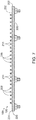
- Fig. 1 is a schematic cross-sectional diagram representing heat transfer devices 100 according to the present disclosure.
- heat transfer devices 100 may be referred to as a thermal management disc.
- Heat transfer device 100 may be configured to draw heat away from (i.e., cool) an external body 102, provide heat to (i.e., heat) external body 102, or both.
- External body 102 may include an active component that generates heat, such as an engine, an electronic device, an electronic component, etc.
- external body 102 may include a component that passively acquires heat from another source, such as a heat shield, a heat sink, etc.
- heat transfer device 100 may be configured to draw heat away from external body 102.
- heat transfer devices 100 include at least a first disc 200, a second disc 300 positioned adjacent to first disc 200, and at least one spacer 400 positioned between first disc 200 and second disc 300. Additionally, first disc 200 and second disc 300 define a fluid channel 500 between first disc 200 and second disc 300.
- First disc 200 has an outer surface 202 proximate to external body 102 and an inner surface 204 located proximate to and that faces second disc 300.
- first disc 200 is circular. However, in various examples, first disc 200 may be different shapes, such as oval, ovoid, square, polygonal, etc.
- First disc 200 defines an aperture 206 that extends through the first disc 200 from outer surface 202 to inner surface 204.
- First disc 200 further includes a pin cooling structure 208 extending from outer surface 202 around aperture 206. In some examples, the angle between pin cooling structure 208 and outer surface 202 is configured to create optimal contact with external body 102.
- pin cooling structure 208 may be perpendicular with outer surface 202 of first disc 200; however, other angular relationships are within the scope of the present disclosure, such as angular relationships based on the packaging (i.e., the arrangement) of heat transfer device 100 with external body 102.
- Pin cooling structure 208 comprises a distal end 210 configured to facilitate heat exchange between pin cooling structure 208 and external body 102.
- Distal end 210 may be composed of one or more materials having a high heat transfer coefficient to ensure efficient heat transfer between external body 102 and pin cooling structure 208.
- An outer surface 222 of distal end 210 may be post-process machined to a mirror finish or a supermirror finish. Outer surface 222 of distal end 210 may also be in-situ machined to a mirror finish.
- thermal grease may be applied to distal end 210 to improve the thermal conductivity between external body 102 and pin cooling structure 208.
- pin cooling structure 208 is made of, comprises, or optionally includes an electrically conductive material.
- pin cooling structures 208 may be electrically conductive and may be a component of an electric circuit. Such a circuit may comprise a singular pin cooling structure 208, a plurality of pin cooling structures 208, insulators, resistors, and/or some other element(s).
- heating and/or cooling pin cooling structures 208 may alter its electrical properties, including but not limited to changing the resistance of the pin cooling structure and/or creating a break in a current path.
- an array of pin cooling structures 208 may exhibit an electrical performance (including digital logic) in a low temperature environment (e.g., cryogenic, sub Antarctic or subarctic) that is distinct from an electrical performance in a heated environment (e.g., atmospheric re-entry). Additionally, where the electrical performance of pin cooling structures 208 is temperature dependent, the electrical performance may be altered via localized cooling and/or heating of individual pin cooling structures 208 within an array of pin cooling structures 208. In this way, when pin cooling structures 208 are in contact with a surface of external body 102, an electrical path between external body 102 and one or more pin cooling structures 208 may be broken by a change in temperature, rather than a breakage of physical contact between external body 102 and individual pin cooling structures 208. Moreover, in some examples, pin cooling structures 208 may be responsive to magnetic fields. For example, individual pin cooling structures 208 may be constructed of a varied functionally gradient material blend that causes the corresponding pin cooling structures 208 to have a varied response to magnetic fields.
- Distal end 210 may have a circular cross section.
- the cross section of distal end 210 may be another shape.
- the cross section of distal end 210 may correspond to a 1:1 projection of portion of external body 102 that pin cooling structure 208 is cooling.
- the cross section of distal end 210 may correspond to, or be different from, the cross sectional shape of one or more other regions of pin cooling structure 208.
- an internal pin volume 214 may have a circular cross-sectional shape while the cross sectional shape of distal end 210 may have a square cross-sectional shape.
- Pin cooling structure 208 further includes one or more side walls 212.
- Side walls 212 at least partially define internal pin volume 214.
- Internal pin volume 214 may be further partially defined by one or more of distal end 210, aperture 206, and second disc 300.
- side walls 212 comprise a micro-bellows 216.
- Micro-bellows 216 is an elastic region of pin cooling structure 208 that can be compressed when pressure is applied to the outside of pin cooling structure 208 and/or may be expanded when a pressure is applied to an internal surface 218 of distal end 210. For example, expansion of micro-bellows 216 causes distal end 210 of pin cooling structure 208 to be translated away from the second disc 300.
- micro-bellows 216 When such pressure is released, micro-bellows 216 is configured to return to its original shape.
- Micro-bellows 216 may include one or more expansion regions 220, such as chevrons, ribs, and/or other corrugated structures, which are capable of expanding or contracting in response to applied pressures.
- internal surface 218 of distal end 210 comprises an inset surface 211 opposite outer surface 222.
- inset surface 211 may be configured to efficiently receive pressure from the fluid in internal pin volume 214 traveling away from aperture 206.
- the inset surface may be a conical surface, a dome surface, etc. In this way, inset surface 211 is able to increase the pressure applied to distal end 210 by the fluid in internal pin volume 214.
- the inset surface 211 may be configured to create turbulence in the flow of the fluid when the fluid strikes inset surface 211.
- the turbulence of the fluid in internal pin volume 214 increases the amount of heat that is absorbed by the fluid from pin cooling structure 208 while the fluid is in internal pin volume 214.
- micro-bellows 216 is configured to expand in response to a fluid being injected into internal pin volume 214 of pin cooling structure 208. Additionally, micro-bellows 216 may be configured to deform in response to distal end 210 of pin cooling structure 208 making contact with external body 102. For example, in response to a force (e.g., a normal force) being exerted on distal end 210 by a surface of external body 102, expansion regions 220 of micro-bellows 216 may deform (i.e., expand, contract, or a combination thereof) so that outer surface 222 of distal end 210 is oriented to more closely parallel the surface of external body 102.
- a force e.g., a normal force
- micro-bellows 216 causes outer surface 222 of distal end 210 to make flush contact with the surface of external body 102. In this way, if the surface of external body 102 and outer surface 222 of distal end 210 are not parallel when contact is made between the bodies, micro-bellows 216 may deform so that outer surface 222 of distal end 210 becomes more parallel to the surface of external body 102.
- First disc 200 may be a monolithic structure, or may be comprised of multiple components.
- first disc 200 may optionally comprise a surface layer 224 that includes pin cooling structure 208, and a rigid layer 226 adjacent to surface layer 224 and disposed between surface layer 224 and second disc 300.
- Surface layer 224 and rigid layer 226 may be composed of the same material, or may be composed of different materials.
- rigid layer 226 may be composed of a material having a lower modulus of elasticity and/or a higher coefficient of thermal expansion than surface layer 224.
- heat transfer devices 100 further include second disc 300 positioned adjacent to first disc 200.
- first disc 200 and second disc 300 are coupled together via at least one of a mechanical fastener, an adhesive, welding, and/or bonding.
- first disc 200 and second disc 300 (as well as other components) may comprise a single body.
- the single body may be formed using additive manufacturing, and may at least partially comprise one or more functionally gradient materials (e.g., a grading from Ti-6AI-4V to Vanadium, where the distal pin ends may be malleable).
- Second disc 300 defines an inlet 302 that allows fluid to pass from inlet 302 and into internal pin volume 214.
- the fluid may correspond to a gas or liquid having the ability to absorb and transport heat, such as a coolant.
- the fluid may be, comprise, or optionally consist of methane and/or methanol gas.
- the fluid may be selected based on many different characteristics such as its ability to efficiently transport heat, ability to remain in a stable condition, a boiling temperature, a freezing temperature, an ability to carry a voltage, etc.
- the fluid may include component elements that improve the stability of the fluid.
- the fluid may include a component element that is itself a fire retardant, or which, when combined with other components of the fluid, prevent the fluid from igniting.
- the fluid may include component elements that improve and or provide a voltage-carrying capability of the fluid.
- the fluid may optionally include a mixture of water and manganese sulfate.
- Inlet 302 comprises at least one internal wall 304 that at least partially defines an internal volume 306, and includes an aperture 307 through which fluid passes between inlet 302 and internal pin volume 214.
- heat transfer devices 100 also may include one or more of a fluid reservoir 310 and a barrier element 312.
- heat transfer devices 100 optionally may include fluid reservoir 310, where the fluid flows from fluid reservoir 310 into inlet 302. The fluid may flow directly from fluid reservoir 310 to inlet 302, or may indirectly flow from fluid reservoir 310 to inlet 302 via one or more conduits.
- the fluid may flow from fluid reservoir 310 based on a passive driver, such as a passive pressure differential between the fluid and inlet 302, and/or based on an applied pressure, such as a pressure applied by a pump.
- a passive driver such as a passive pressure differential between the fluid and inlet 302
- an applied pressure such as a pressure applied by a pump.
- the fluid may passively flow from fluid reservoir 310 to inlet 302 in response to the temperature of the fluid as stored in fluid reservoir 310 causing the fluid to have a fluid pressure that is greater than the pressure within inlet 302.
- the fluid may flow from fluid reservoir 310 to inlet 302 in response to a trigger event.
- heat transfer device 100 may include one or more barrier elements 312 (e.g., burst discs, permeable membranes, plungers, release valves, pressure release valves, check valves, pyrotechnic valves, solenoid valves, ball and spring valves, etc.) that allow the fluid to flow from fluid reservoir 310 to inlet 302 when in an open configuration, and that restrict the fluid from flowing from fluid reservoir 310 to inlet 302 when in a closed configuration.
- barrier elements 312 may be configured to transform from the closed configuration to the open configuration in response to a trigger event.
- Example trigger events include heat transfer device 100 reaching a trigger temperature, the fluid reaching a trigger pressure, or an external stimulus triggering barrier element 312 to open.
- barrier element 312 is a permeable membrane
- a pressure that the fluid is exerting on the membrane may cause the fluid to flow across the membrane when the exerted pressure exceeds a threshold level.
- barrier element 312 may be a burst disc that is configured to rupture when the fluid reaches a threshold pressure and/or temperature.
- a burst disc may be ruptured by a rupturing element, such as a puncture needle, a plunger, etc. when the fluid reaches a threshold pressure and/or temperature.
- barrier element 312 may transition from a closed configuration to an open configuration in response to an outside stimulus, such as the initiation of an electronic device, a sensor detecting a threshold temperature, a cooling protocol being initiated, etc.
- the outside stimulus may be transmitted via a physical stimulus or an electronic stimulus/signal.
- the barrier elements 312 may be formed from one or more of an elastomeric, polymeric, and metallic material. Alternatively or in addition, the barrier elements 312 may be formed from one or more of carbon steel, stainless steel, nickel-molybdenum alloys such as Hastelloy®, graphite, aluminum, silicone, and a high temperature rubber compound. In various examples, the barrier elements 312 may be located in an aperture that is shaped as a venturi, e.g., having a narrow section located between two wider sections. Alternatively, a corresponding aperture may be conically-shaped with a base of the cone positioned radially outward. In yet another example, a corresponding aperture may be a cylindrical orifice. In such an example, the cylindrical aperture functions as the narrow portion of a venturi.
- heat transfer devices 100 include fluid channel 500 defined between first disc 200 and second disc 300.
- Fluid channel 500 is at least partially defined by inner surface 204 of first disc 200 and an inner surface 318 of second disc 300. Fluid channel 500 is in fluid communication with internal pin volume 214.
- aperture 206 of first disc 200 may open into fluid channel 500 to allow for fluid to pass between aperture 206 and fluid channel 500. Fluid channel 500 then allows the fluid to flow away from internal pin volume 214.
- fluid channel 500 may allow the fluid to flow radially away from the internal pin volume 214.
- fluid channel 500 may further be partially defined by one or more channel walls 502 that restrict the fluid so that it flows away from internal pin volume 214 along one or more flow pathways.
- heat transfer devices 100 include one or more exit interfaces 320 that partially define fluid channel 500.
- Exit interface 320 allows fluid to flow from fluid channel 500 to an effusion region 308 (e.g. a storage receptacle, a sewer, an environment of the heat transfer device, etc.) via exit interface 320.
- effusion region 308 e.g. a storage receptacle, a sewer, an environment of the heat transfer device, etc.
- fluid flowing through fluid channel 500 may be exhausted from fluid channel 500 by passing through the at least one exit interface 320 and into effusion region 308.
- heat transfer devices 100 include a chimney 322 through which the fluid is able to flow from fluid channel 500 and through one of first disc 200 and second disc 300.
- the fluid is exhausted from fluid channel 500 by flowing through chimney 322 and to an exhaustion, diffusion, and/or effusion region.
- Fig. 1 shows chimney 322 as being defined by second disc 300; however, in other examples, chimney 322 may be at least partially defined by first disc 200, the second disc 300, another component, or a combination thereof.
- inlet 302 optionally may comprise an injector 314 extending from inlet 302 and into internal pin volume 214.
- Injector 314 may define an internal pin channel 316 that is in fluid communication with both inlet 302 and internal pin volume 214.
- injector 314 may extend past fluid channel 500 and/or aperture 307.
- internal pin channel 316 provides a flow path through which the fluid can pass from inlet 302 and into internal pin volume 214 at a location beyond fluid channel 500 and in some examples even beyond aperture 307.
- the fluid will flow out of injector 314 and toward internal surface 218 of distal end 210, preventing the fluid from partially and/or entirely flowing into fluid channel 500.
- injector 314 increases the amount of fluid that applies pressure to internal surface 218 of distal end 210 as well as the amount of turbulence created within internal pin volume 214.
- Heat transfer devices 100 further include at least one spacer 400 positioned between first disc 200 and second disc 300. At least one spacer 400 may be in contact with inner surface 204 of first disc 200 and inner surface 318 of second disc 300. One or more spacers 400 define a separation 402 between inner surface 204 of first disc 200 and inner surface 318 of second disc 300.
- the at least one spacer 400 is configured to allow fluid to pass from internal pin volume 214 to fluid channel 500. That is, at least one spacer 400 both defines separation 402 of fluid channel 500 while also providing a flow path between internal pin volume 214 and fluid channel 500.
- at least one spacer 400 is a plurality of separate spacers, where the spacers partially define a spacer flow pathway 404 between internal pin volume 214 and fluid channel 500.
- spacer flow pathway 404 may correspond to a volume partially defined by two spacers of the plurality of separate spacers.
- spacer flow pathway 404 may correspond to an internal flow way 406 defined within a spacer, and at least partially defined by the corresponding spacer. In this way, internal flow way 406 allows the fluid to flow from internal pin volume 214 and fluid channel 500 by passing through the corresponding spacer.
- One or more component elements of heat transfer device 100 may be formed from plastics, polymers and/or elastomers including but not limited to Nylon, acrylonitrile butadiene styrene, polyactic acid, polyetherimide (ULTEM®), Carbon fiber, para-aramid synthetic fibers (Kevlar®), polychlorotrifluoroethylene, polytetrafluoroethylene (TeflonTM), and polyethylene terephthalate.
- portions of the structure may be constructed of flexible material for purposes of resiliency to high-vibration regimes, flexure in aero elastic applications.
- component elements of heat transfer device 100 may be constructed with non-thermoplastic materials, including epoxies, including high-temp resistant epoxies.
- one or more component elements of heat transfer device 100 may partially and/or completely comprise one or more shape memory alloys.
- component elements of heat transfer device 100 may optionally include support materials, such as support materials for plastics, polymers and/or elastomers like PVA or metallic materials, including water-soluble crystals and other melt-aways, including, but not limited to Cu, Ag, Al, Sb, Zn, and Sn.
- support materials such as support materials for plastics, polymers and/or elastomers like PVA or metallic materials, including water-soluble crystals and other melt-aways, including, but not limited to Cu, Ag, Al, Sb, Zn, and Sn.
- Such support materials may also include other alloys having a low soldering point and/or melting point such as Ag alloy solder (Ag-Sn-Pb, Ag-Pb, Ag-Sn, Ag-Sn-Cu, Ag-Cd-Zn, Ag-Cd), polyethylene, polyamide, polyimide, polyolefin, polyprophylene, polypropylene, polystyrene, PMMA, polyether sulfone, thermoplastic polyester, copolymer or polyhexafluroropropylene and polytetrafluoroethylene, polyfluorovinylidene, and other organic composite photoresist materials (including but not limited to dry film type resist).
- Ag alloy solder Ag-Sn-Pb, Ag-Pb, Ag-Sn, Ag-Sn-Cu, Ag-Cd-Zn, Ag-Cd
- polyethylene polyamide, polyimide, polyolefin, polyprophylene, polypropylene, polystyrene, PMMA, poly
- Example additive manufacturing methods and printers include, but are not limited to, VAT photopolymerization, powder bed fusion, binder jetting, bronze infusion/infiltration, material jetting, sheet lamination, material extrusion, directed energy deposition, directed metal laser sintering, direct metal printing, electron beam additive manufacturing, electron beam melting, electron beam powder bed, fused deposition modeling, indirect power bed, laser cladding technology, laser deposition technology, laser deposition welding, laser deposition welding with integrated milling, laser engineering net shape, laser freeform manufacturing technology, laser metal deposition-powder, laser metal deposition-wire, laser powder bed, laser puddle deposition, laser repair technology, powder directed energy deposition, stereolithography, selective laser melting, selective laser sintering, small puddle deposition, atomic diffusion additive manufacturing, Big Area Additive Manufacturing, Bound Metal Deposition, composite-based additive manufacturing, digital light processing, digital light synthesis, gel dispensing printing, high-speed sinter
- Potential additive manufacturing materials include metals such as steel, stainless steel, Elgiloy®, titanium, copper, bronze, Hastalloy, zinc, aluminum, nickel alloys, and alloys thereof, including but not limited to IN600, IN625, IN718, Ti-6AI-4V, AlSi10Mg, SS316, Monel, Monel K500, Copper, Ti-5553, Ti-6AI-6V-2Sn, Ti-6242, Maraging Steel MSI 18, Mar 300, 316L, 17-4, 15-4, Cobalt Chrome SP2, Zircalloy, Niobium (NB), Molybdenum, Vitallium, Vanadium, Ti-6AI-4V ELI, Nickel Alloy HX, gold (au), silver (ag), as well as plastics, polymers and/or elastomers, including Acrylonitile Butadiene Styrene (ABS), Polylactic acid (PLA), Polyvinyl Chloride, PTFE, Acetal, Delrin®, Polyvinyl alcohol, and Polycarbonate,
- Heat transfer device 100 disclosed herein may also be partially or completely formed of, or may otherwise include functionally gradient materials.
- the component elements of heat transfer device 100 optionally may be formed by altering the blending of deposited additively manufactured material such that functionally gradient material properties may be achieved, including varying the Coefficient of Thermal Expansion (CTE).
- CTE Coefficient of Thermal Expansion
- Figs. 2-9 illustrative non-exclusive examples of heat transfer devices 100 are illustrated.
- the reference numerals from the schematic illustrations of Fig. 1 are used to designate corresponding parts of the examples of Figs. 2-9 ; however, the examples of Figs. 2-9 are non-exclusive and do not limit heat transfer devices 100 to the illustrated examples of Figs. 2-9 . That is, heat transfer devices 100 are not limited to the specific examples depicted in Figs. 2-9 , and heat transfer devices 100 may incorporate any number of the various aspects, configurations, characteristics, properties, etc. of heat transfer devices that are illustrated in and discussed with reference to the schematic representations of Fig. 1 and/or the examples of Figs.
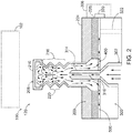
- Fig. 2 illustrates a cross section of an example 120 of heat transfer devices 100 comprising micro-bellows 216 and constructed of multiple component elements.
- example 120 of heat transfer device 100 includes surface layer 224 that includes pin cooling structure 208, rigid layer 226 adjacent to surface layer224, and second disc 300 defining inlet 302 and positioned adjacent to rigid layer 226 such that rigid layer 226 is disposed between surface layer 224 and second disc 300.
- the component elements of heat transfer device 100 i.e., surface layer224, rigid layer226, and second disc 300
- individual components may be printed using additive manufacturing. When the component elements are generated separately, this allows a quality control check to be conducted to ensure proper formation before assembly of the heat transfer device 100.
- the component elements of heat transfer device 100 may individually be composed of a same material, may be composed of different materials, or a combination thereof.
- rigid layer 226 and second disc 300 may be composed of a material having a lower modulus of elasticity and/or a higher coefficient of thermal expansion than surface layer 224.
- surface layer 224 may be composed of a material having a higher thermal conductivity and/or electrical conductivity, allowing pin cooling structures 208 to be a better conduit for the flow of heat and/or electricity between external body 102 and heat transfer device 100.
- Fig. 2 also shows the fluid pathway of fluid within heat transfer device 100.
- Fig. 2 shows fluid flowing into inlet 302.
- the fluid may flow into inlet 302 directly or indirectly from fluid reservoir 310.
- the fluid then flows out of injector 314 extending from inlet 302 and into internal pin volume 214.
- Fig. 2 shows the fluid pathway as optionally narrowing between inlet 302 and injector 314. This narrowing causes an increase in the velocity of the fluid as it enters internal pin volume 214.
- the increase in velocity of the fluid as it enters internal pin volume 214 increases the pressure applied to distal end 210 of pin cooling structure 208 when the fluid impacts internal surface 218 of distal end 210.
- This pressure applied to the distal end causes micro-bellows 216 to expand, which in turn causes distal end 210 of pin cooling structure 208 to be translated away from second disc 300.
- one or more expansion regions 220 e.g., chevrons and/or ribs
- This translation increases the amount of heat that flows into pin cooling structure 208 from external body 102.
- the translation may cause distal end 210 to be more proximate to external body 102, increasing the amount of heat transmitted via radiation and/or convection to pin cooling structure 208 from external body 102.
- the translation may cause distal end 210 to make physical contact and/or make a more flush contact with a surface of external body 102, allowing and/or increasing the heat transmitted between pin cooling structures 208 from external body 102 via conduction.
- the fluid impacting internal surface 218 of distal end 210 also causes flow turbulence within internal pin volume 214.
- This turbulence increases the opportunity for heat to flow from pin cooling structure 208 and into the fluid in internal pin volume 214.
- Fig. 2 further shows the fluid (and the heat absorbed from pin cooling structure 208 while the fluid was in internal pin volume 214) flowing out of internal pin volume 214 and into fluid channel 500.
- the fluid may flow past, between, and/or through one or more spacers 400.
- the fluid and the heat then flow within fluid channel 500 away from pin cooling structure 208.
- the fluid and the heat may flow into chimney 322 and/or exit interface 320 where it is exhausted into effusion/diffusion region 308, such as a storage receptacle, a sewer, an environment of the heat transfer device, etc.
- Fig. 3 illustrates a cross section of an example 130 of heat transfer devices 100 showing a plurality of pin cooling structures 208, and composed of a monolithic structure.
- each of first disc 200, second disc 300 positioned adjacent to rigid layer 226, and one or more spacers 400 of example 130 of heat transfer device 130 are formed of a single body.
- the single body may be formed using additive manufacturing, and may at least partially comprise one or more functionally gradient materials and/or shape memory alloys.
- Fig. 3 also shows first disc 200 as defining a plurality of apertures 206 and a plurality of pin cooling structures 208, wherein individual pin cooling structures 208 extend from corresponding aperture 206.
- second disc 300 as comprising a plurality of inlets 302, wherein each inlet 302 of the plurality of inlets 302 is configured to allow the fluid to flow from inlet 302 and into a corresponding internal pin volume 214 defined by a corresponding pin cooling structure 208 of the plurality of pin cooling structures 208.
- Figs. 4-5 illustrate cross sections of the unique AM (i.e. Additive Manufactured) heat transfer device 100 that illustrate the flow of fluid into fluid channel 500.
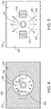
- Fig. 4 illustrates cross sections of an example of the aperture 206 of first disc 200 according to the present disclosure. Specifically, Fig. 4 illustrates a cross section of first disc 200 and aperture 206 which depicts inlet 302 defined by second disc 300, and a plurality of spacers 400. Fig. 4 also shows fluid pathways where the fluid is able to flow into fluid channel 500 around and/or between spacers 400.
- Fig. 5 illustrates cross sections of an example of fluid channel 500 according to the present disclosure. Specifically, Fig.
- FIG. 5 illustrates a cross section of the plurality of spacers 400 and fluid channel 500 which depicts inlet 302 defined by second disc 300.
- Fig. 5 further illustrates fluid pathways along which the fluid is able to flow through fluid channel 500 away from inlet 302.
- Fig. 5 further shows optional channel walls 502 that restrict the fluid so that it flows away from inlet 302 through a particular channel flow pathway 600.
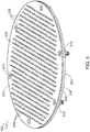
- Figs. 6-7 are a perspective view and a side view of heat transfer device 100.
- Figs. 6-7 show first disc 200 coupled to second disc 300 via a plurality of attaching mechanisms 610.
- Figs. 6-7 illustrate attaching mechanisms 610 as being counter sunk threaded fasteners, which enable the attaching mechanisms 610 to be flush with outer surface 202 of first disc 200.
- attaching mechanisms 610 may correspond to any combination of mechanical fasteners, adhesives, welding, and/or bonding between first disc 200 and second disc 300.
- heat transfer device 100 further comprises an adapter configured to affix the heat transfer device to a separate component.
- first disc 200 may be made up of surface layer 224 and rigid layer 226.
- Figs. 6-7 also show a plurality of pin cooling structures 208 that extend from outer surface 202 of first disc 200.
- Fig. 6 shows heat transfer device 100 as having a circular shape. However, in other examples the heat transfer device may have another shape, such as oval, ovoid, square, polygonal, etc. In some examples, the shape of heat transfer device 100 may reflect or otherwise be based on a shape and/or characteristics of a separate body 102. Moreover, in some examples, heat transfer device 100 may conformably wrap about a toroid, Vesica Pisces and/or thruster shape.
- the plurality of pin cooling structures 208 are illustrated in Fig. 6 as being arranged in a matrix array.
- pin cooling structures 208 may be arranged in any number of arrays such as radially symmetric patterns, offset matrix arrays, circular arrays, polygonal arrays, etc. Additionally, the arrangement of pin cooling structures 208 may be designed to reflect and/or align with external/separate body 102. For example, pin cooling structures 208 may be positioned so that they align with and/or contact regions of external/separate body 102 that generate and/or absorb excess heat.
- Fig. 8 is a perspective view of example 120 of heat transfer device 100 of Fig. 2 illustrating a temperature based deformation thereof.
- Fig. 8 shows a deformation pattern (i.e., an altered shape or geometry) of example 120 of heat transfer device 100 based on a temperature of heat transfer device 100.
- first disc 200, second disc 300, or both may deform. That is, first disc 200 and/or second disc 300 may be composed of materials that deform responsive to a temperature change.
- materials of first disc 200 and/or second disc 300 may be configured to so that heat transfer device 100 achieves a target deformation pattern (i.e., a desired shape or geometry) when heat transfer device 100 reaches a target temperature.
- a target deformation pattern i.e., a desired shape or geometry
- first disc 200 and second disc 300 may be composed of functionally gradient materials, where the properties (e.g., the coefficient of thermal expansion) of the functionally gradient materials are varied such as to cause one or both of first disc 200 and second disc 300 to achieve a target geometry when heat transfer device 100 reaches a target/threshold temperature.
- properties e.g., the coefficient of thermal expansion
- first disc 200 and/or second disc 300 are configured such that the patterns of the deformation of first disc 200 and/or second disc 300 responsive to a temperature change may be characterized by one or more mathematical representations, such as, for example, via a periodic convolution and/or periodic summation of one or more Zernike polynomials.
- Example Zernike polynomials may include sec spherical, primary septafoil, sec trefoil, sec tetrafoil, etc.
- first disc 200 and/or second disc 300 causes pin cooling structures 208 to be translated as the temperature of heat transfer device 100 increases. Such a translation may correspond to pin cooling structures 208 moving to a position more proximate to and/or better aligning with external body 102.
- Fig. 9 is a perspective view of example 120 of heat transfer device 100 as a component portion of a heat transfer puck 150 according to the present disclosure.
- Fig. 9 illustrates heat transfer apparatus 700 where heat transfer device 100 is mounted to the heat transfer puck 150.
- the heat transfer puck 150 may include a mechanism for releasing fluid. Once the fluid is released by heat transfer puck 150, the fluid may flow into inlet 302 of heat transfer device 100. The fluid may then flow along a fluid pathway through heat transfer device 100. In this way, in response to heat transfer puck 150 releasing the fluid, heat transfer device 100 may cool external body 102.
- heat transfer puck 150 may include one or more reservoirs for storing fluid. Alternatively, heat transfer puck 150 may selectively receive fluid from an external reservoir, and allow the fluid to subsequently flow to the heat transfer device 100.
- Heat transfer device 100 may comprise an adapter configured to affix heat transfer device 100 to heat transfer puck 150 or other device(s).
- the adapter may correspond to, or be separate from attaching mechanisms 610.
- Heat transfer device 100 may be located within and/or affixed to a structure that is impenetrable by non-destructive Inspection (NDI) devices, including, but not limited to, x-ray (radiography), computed tomography (CT) scanning, ultrasonic testing (UT), etc.
- NDI non-destructive Inspection
- heat transfer device 100 may be connected (including electrically) to one or more other devices that are identical or non-identical in properties including electrical and/or mechanical performance.
- Heat transfer device 100 may rotate, revolve, and/or translate with respect to an attaching surface and/or other devices (such as via bearings and/or electrically conductive bearings).
- heat transfer device 100 may rotate, revolve, and/or translate
- heat transfer device 100 may be functional in a singular position with respect to another surface, and/or in a plurality of positions with respect to the another surface. Additionally, the heat transfer device 100 may exhibit an altered performance (including mechanical performance and/or electrical performance) when based on the position of heat transfer device 100 of the plurality of positions.
- Fig. 10 schematically provides a flowchart that represents illustrative, non-exclusive examples of methods 1000 according to the present disclosure.
- some steps are illustrated in dashed boxes indicating that such steps may be optional or may correspond to an optional version of a method according to the present disclosure. That said, not all methods according to the present disclosure are required to include the steps illustrated in solid boxes.
- the methods and steps illustrated in Fig. 10 are not limiting and other methods and steps are within the scope of the present disclosure, including methods having greater than or fewer than the number of steps illustrated, as understood from the discussions herein.
- Fig. 10 is a flowchart schematically representing methods for conducting heat transfer with an external/separate body according to the present disclosure.
- Methods 1000 include flowing a fluid from inlet 302 and into internal pin volume 214 at 1002.
- the fluid may be flowed from inlet 302 defined by second disc 300 of heat transfer device 100 and into internal pin volume 214 defined by pin cooling structure 208.
- Pin cooling structure 208 is a component of first disc 200 of heat transfer device 100.
- First disc 200 is positioned adjacent to second disc 300.
- the fluid may flow from inlet 302 based on a passive driver, such as a passive pressure differential between the fluid and inlet 302, and/or based on an applied pressure, such as a pressure applied by a pump.
- the flowing of the fluid from inlet 302 in step 1002 may further comprise flowing the fluid from fluid reservoir 310 and into inlet 302.
- the fluid may flow directly from fluid reservoir 310 to inlet 302, or may indirectly flow from fluid reservoir 310 to inlet 302 via one or more conduits.
- heat transfer device 100 includes barrier element 312 (e.g., a burst disc, a permeable membrane, a plunger, a release valve, a pressure release valve, a check valve, a pyrotechnic valve, a solenoid valve, a ball and spring valve, etc.), the flowing of the fluid from inlet 302 may be in response to a trigger event.
- Example trigger events may include heat transfer device 100 reaching a trigger temperature; the fluid reaching a trigger pressure; or an external stimulus triggering barrier element 312 to open.
- Methods 1000 optionally may include translating distal end 210 of the pin cooling structure 208 away from first disc 200.
- the translating of distal end 210 may include causing the distal end 210 to contact an external body 102.
- the translation of distal end 210 may be based at least in part on the fluid flowing into internal pin volume 214.
- pin cooling structure 208 comprises micro-bellows 216, and wherein the translating distal end 210 of pin cooling structure 208 toward external body 102 corresponds at least in part to micro-bellows 216 expanding.
- Micro-bellows 216 is an elastic vessel that can be expanded when a pressure is applied to internal surface 218 of distal end 210.
- micro-bellows 216 For example, expansion of micro-bellows 216 causes distal end 210 of pin cooling structure 208 to be translated away from second disc 300.
- Micro-bellows 216 may include one or more expansion regions 220, such as chevrons and/or ribs, which are capable of expanding or contracting in response to applied pressures.
- internal surface 218 of distal end 210 comprises inset surface 211 opposite aperture 206.
- inset surface 211 may be configured to efficiently receive pressure from the fluid in internal pin volume 214 traveling away from aperture 206.
- Methods 1000 also may optionally include deforming at least one of first disc 200 and second disc 300 based on a change in temperature at step 1006.
- first disc 200 and/or second disc 300 may be composed of materials that deform responsive to a temperature change.
- materials of first disc 200 and/or second disc 300 may be configured so that heat transfer device 100 achieves a target shape when heat transfer device 100 reaches a target temperature.
- one or both of first disc 200 and second disc 300 may be composed of functionally gradient materials, where the properties of the functionally gradient materials cause one or both of first disc 200 and second disc 300 to achieve a target shape when heat transfer device 100 reaches a target/threshold temperature.
- first disc 200 and/or second disc 300 responsive to a temperature change may be characterized by one or more mathematical representations, such as, for example, one or more Zernike polynomials. Additionally, the deformation may cause pin cooling structures 208 extending from first disc 200 to be translated as the temperature of heat transfer device 100 increases.
- heat is transferred between external body 102 and the fluid within internal pin volume 214 via pin cooling structure 208.
- heat may first be transferred between external/separate body 102 and pin cooling structure 208, and then subsequently transferred from pin cooling structure 208 and to the fluid within internal pin volume 214.
- the heat may be transferred by any combination of conduction, radiation, and convection.
- Fluid channel 500 is at least partially defined by second disc 300 and first disc 200.
- the fluid flows through a spacer flow pathway 404 defined by a combination of inner surface 204 of first disc 200, inner surface 318 of second disc 300 and a plurality of spacers 400.
- spacer flow pathway 404 may correspond to a volume partially defined by two spacers of the plurality of separate spacers 400.
- spacer flow pathway 404 may correspond to an internal flow way 406 defined within spacer 400, and at least partially defined by corresponding spacer 400. In this way, internal flow way 406 allows the fluid to flow from internal pin volume 214 and fluid channel 500 by passing through corresponding spacer 400.
- methods 1000 also may optionally include exhausting the fluid from heat transfer device 100.
- the fluid may flow within fluid channel 500 until it reaches exit interface 320 and/or chimney 322.
- the fluid may then be exhausted into effusion/diffusion region 308, such as a storage receptacle, a sewer/chimney, an environment of the heat transfer device, etc.
- effusion/diffusion region 308, such as a storage receptacle, a sewer/chimney, an environment of the heat transfer device, etc.
- the terms “adapted” and “configured” mean that the element, component, or other subject matter is designed and/or intended to perform a given function. Thus, the use of the terms “adapted” and “configured” should not be construed to mean that a given element, component, or other subject matter is simply “capable of” performing a given function but that the element, component, and/or other subject matter is specifically selected, created, implemented, utilized, programmed, and/or designed for the purpose of performing the function. It is also within the scope of the present disclosure that elements, components, and/or other recited subject matter that is recited as being adapted to perform a particular function may additionally or alternatively be described as being configured to perform that function, and vice versa. Similarly, subject matter that is recited as being configured to perform a particular function may additionally or alternatively be described as being operative to perform that function.
- the term "and/or" placed between a first entity and a second entity means one of (1) the first entity, (2) the second entity, and (3) the first entity and the second entity.
- Multiple entries listed with “and/or” should be construed in the same manner, i.e., "one or more" of the entities so conjoined.
- Other entities optionally may be present other than the entities specifically identified by the "and/or” clause, whether related or unrelated to those entities specifically identified.
- a reference to "A and/or B," when used in conjunction with open-ended language such as “comprising,” may refer, in one example, to A only, as well as reoccurring absence/presence of A only, (optionally including entities other than B); in another example, to B only, as well as reoccurring absence/presence of B only, (optionally including entities other than A); in yet another example, to both A and B, as well as reoccurring absence/presence of A and B, (optionally including other entities).
- These entities may refer to elements, actions, structures, steps, operations, values, and the like.
Landscapes
- Engineering & Computer Science (AREA)
- Microelectronics & Electronic Packaging (AREA)
- Physics & Mathematics (AREA)
- Thermal Sciences (AREA)
- Mechanical Engineering (AREA)
- General Engineering & Computer Science (AREA)
- Cooling Or The Like Of Electrical Apparatus (AREA)
Claims (15)
- Wärmeübertragungsvorrichtung (100), die aufweist:
eine erste Scheibe (200), die eine Öffnung (206) definiert und die eine Stiftkühlstruktur (208) aufweist, die sich um die (206) erstreckt, wobei die Stiftkühlstruktur (208) aufweist:ein distales Ende (210), das zum Vereinfachen eines Wärmeaustauschs zwischen der Stiftkühlstruktur (208) und einem externen Körper (102) eingerichtet ist; undeine oder mehrere Seitenwände (212), wobei die eine oder mehreren Seitenwände (212), das distale Ende (210) und/oder die Öffnung (206) zumindest teilweise ein inneres Stiftvolumen (214) definieren;eine zweite Scheibe (300), die benachbart zur ersten Scheibe (200) positioniert ist und die einen Einlass (302) definiert, wobei der Einlass (302) eingerichtet ist:ein Fluid aufzunehmen; unddas Fluid vom Einlass (302) und in das innere Stiftvolumen (214) strömen zu lassen;zumindest einen Abstandshalter (400), der zwischen der ersten Scheibe (200) und der zweiten Scheibe (300) positioniert ist; undwobei ein Fluidkanal (500) zwischen der ersten Scheibe (200) und der zweiten Scheibe (300) definiert ist und wobei der Fluidkanal (500) in fluidischer Kommunikation mit dem inneren Stiftvolumen (214) steht. - Wärmeübertragungsvorrichtung (100) nach Anspruch 1, wobei die erste Scheibe (200), die zweite Scheibe (300) und der zumindest eine Abstandshalter (400) aus einem einzigen Körper gebildet sind.
- Wärmeübertragungsvorrichtung (100) nach Anspruch 1 oder 2, wobei die zweite Scheibe (300) ferner eine Injektionseinrichtung (314) aufweist, die sich vom Einlass (302) und in das innere Stiftvolumen (214) erstreckt und wobei die Injektionseinrichtung (314) einen Stiftkanal (316) definiert, der eingerichtet ist, das Fluid vom Einlass (302) und in das innere Stiftvolumen (214) strömen zu lassen.
- Wärmeübertragungsvorrichtung (100) nach einem der Ansprüche 1-3, wobei die Stiftkühlstruktur (208) ferner einen Mikrofaltenbalg (216) aufweist, der eingerichtet ist, sich in Reaktion auf das Fluid auszudehnen, das in das innere Stiftvolumen (214) der Stiftkühlstruktur (208) injiziert wird.
- Wärmeübertragungsvorrichtung (100) nach Anspruch 4, wobei der Mikrofaltenbalg (216) eingerichtet ist, sich in Reaktion darauf zu verformen, dass das distale Ende (210) der Stiftkühlstruktur (208) mit dem externen Körper (102) in Kontakt kommt.
- Wärmeübertragungsvorrichtung (100) nach einem der Ansprüche 1-5, die ferner ein Fluidreservoir (310) aufweist, das eingerichtet ist, das Fluid in den Einlass (302) aus dem Fluidreservoir (310) strömen zu lassen, und wobei die Wärmeübertragungsvorrichtung (100) eingerichtet ist, das Fluid in den Einlass (302) von dem Fluidreservoir (310) in Reaktion auf ein Auslöseereignis strömen zu lassen.
- Wärmeübertragungsvorrichtung (100) nach einem der Ansprüche 1-6, wobei die erste Scheibe (200) ferner eine Vielzahl von Öffnungen (206) definiert und ferner eine Vielzahl von entsprechenden Stiftkühlstrukturen (208) aufweist, und wobei die zweite Scheibe (300) ferner eine Vielzahl von Einlässen (302) aufweist, wobei jeder Einlass (302) der Vielzahl von Einlässen (302) eingerichtet ist, das Fluid von jedem Einlass (302) und in ein entsprechendes inneres Stiftvolumen (214) strömen zu lassen, das durch eine entsprechende Stiftkühlstruktur (208) der Vielzahl von Stiftkühlstrukturen (208) definiert wird.
- Wärmeübertragungsvorrichtung (100) nach einem der Ansprüche 1-7, wobei die erste Scheibe (200) und die zweite Scheibe (300) eingerichtet sind, sich in Reaktion auf eine Temperaturänderung der Wärmeübertragungsvorrichtung (100) zu verformen, und wobei eine Verformung der ersten Scheibe (200) und der zweiten Scheibe (300) in Reaktion auf die Temperaturänderung die Stiftkühlstruktur (208) sich bewegen lässt, wenn sich die Temperatur der Wärmeübertragungsvorrichtung (100) ändert.
- Wärmeübertragungsvorrichtung (100) nach Anspruch 8, wobei die erste Scheibe (200) und die zweite Scheibe (300) derart eingerichtet sind, dass die Verformung der ersten Scheibe (200) und der zweiten Scheibe (300) die Wärmeübertragungsvorrichtung (100) ein Zielverformungsmuster erzielen lässt, wenn die Wärmeübertragungsvorrichtung (100) eine Zieltemperatur erreicht.
- Wärmeübertragungsvorrichtung (100) nach Anspruch 9, wobei die erste Scheibe (200) und/oder die zweite Scheibe (300) aus funktionalen Gradientenmaterialien gebildet sind, und wobei die funktionalen Gradientenmaterialien eingerichtet sind, die Wärmeübertragungsvorrichtung (100) die geänderte Form erzielen zu lassen, wenn die Wärmeübertragungsvorrichtung (100) die Zieltemperatur erreicht.
- Wärmeübertragungsvorrichtung (100) nach einem der Ansprüche 1-10, wobei die erste Scheibe (200) aufweist:eine Flächenschicht (224), die die Stiftkühlstruktur (208) umfasst; undeine steife Schicht (226), die benachbart zur Flächenschicht (224) ist und die zwischen der Flächenschicht (224) und dem Fluidkanal (500) angeordnet ist, wobei die steife Schicht (226) teilweise den Fluidkanal (500) definiert und wobei die steife Schicht (226) aus einem Material gebildet ist, das einen niedrigeren Elastizitätsmoduls und einen höheren Wärmeausdehnungskoeffizienten (Coefficient of Thermal Expansion, CTE) als die Flächenschicht (224) aufweist.
- Verfahren (1000) zum Durchführen eines Wärmeaustauschs mit einem externen Körper (102), das aufweist:Strömen (1002) eines Fluids von einem Einlass (302), der durch eine zweite Scheibe (300) einer Wärmeübertragungsvorrichtung (100) gemäß einem der Ansprüche 1-11 definiert wird, und in ein inneres Stiftvolumen (214), das durch eine Stiftkühlstruktur (208) definiert wird, wobei die Stiftkühlstruktur (208) eine Komponente einer ersten Scheibe (200) der Wärmeübertragungsvorrichtung (100) ist und wobei die erste Scheibe (200) benachbart zur zweiten Scheibe (300) ist;Übertragen (1008) von Wärme zwischen dem externen Körper (102) und dem Fluid innerhalb des inneren Stiftvolumens (214) über die Stiftkühlstruktur (208); undStrömen (1010) des Fluids von dem inneren Stiftvolumen (214) zu einem Fluidkanal (500), wobei der Fluidkanal (500) durch die zweite Scheibe (300) und die erste Scheibe (200) definiert ist.
- Verfahren (1000) nach Anspruch 12, wobei ein Übertragen von Wärme zwischen dem externen Körper (102) und dem Fluid innerhalb des inneren Stiftvolumens (214) aufweist:Aufnehmen von Wärme von dem externen Körper (102) durch die Stiftkühlstruktur (208); undÜbertragen der Wärme, um von der Stiftkühlstruktur (208) an das Fluid innerhalb des inneren Stiftvolumen (214) zu strömen.
- Verfahren (1000) nach Anspruch 12 oder 13, wobei die Stiftkühlstruktur (208) einen Mikrofaltenbalg (216) aufweist, und wobei das Bewegen (1004) des distalen Endes (210) der Stiftkühlstruktur (208) in Richtung des externen Körpers (102) zumindest teilweise einem Ausdehnen des Mikrofaltenbalgs (216) entspricht.
- Verfahren (1000) nach einem der Ansprüche 12-14, das ferner ein Verformen (1006) der zweiten Scheibe (300) der Wärmeübertragungsvorrichtung (100) und/oder der ersten Scheibe (200) der Wärmeübertragungsvorrichtung (100) basierend auf einer Temperaturänderung der Wärmeübertragungsvorrichtung (100) aufweist, und wobei das Bewegen (1004) des distalen Endes (210) der Stiftkühlstruktur (208) zumindest teilweise auf dem Verformen (1006) von einer oder mehreren Scheiben (200, 300) basiert.
Applications Claiming Priority (1)
| Application Number | Priority Date | Filing Date | Title |
|---|---|---|---|
| US16/048,625 US10976119B2 (en) | 2018-07-30 | 2018-07-30 | Heat transfer devices and methods of transfering heat |
Publications (2)
| Publication Number | Publication Date |
|---|---|
| EP3606307A1 EP3606307A1 (de) | 2020-02-05 |
| EP3606307B1 true EP3606307B1 (de) | 2020-12-02 |
Family
ID=67211479
Family Applications (1)
| Application Number | Title | Priority Date | Filing Date |
|---|---|---|---|
| EP19180553.0A Active EP3606307B1 (de) | 2018-07-30 | 2019-06-17 | Wärmeübertragungsvorrichtungen und verfahren zur übertragung von wärme |
Country Status (3)
| Country | Link |
|---|---|
| US (1) | US10976119B2 (de) |
| EP (1) | EP3606307B1 (de) |
| CN (1) | CN110785051B (de) |
Cited By (1)
| Publication number | Priority date | Publication date | Assignee | Title |
|---|---|---|---|---|
| US11950394B2 (en) | 2021-10-12 | 2024-04-02 | Ge Aviation Systems Llc | Liquid-cooled assembly and method |
Families Citing this family (16)
| Publication number | Priority date | Publication date | Assignee | Title |
|---|---|---|---|---|
| WO2020210587A1 (en) | 2019-04-10 | 2020-10-15 | Jetcool Technologies, Inc. | Thermal management of electronics using co-located microjet nozzles and electronic elements |
| EP3977832B1 (de) | 2019-04-14 | 2025-06-04 | Jetcool Technologies, Inc. | Flüssigkeitsbasiertes kühlmodul mit direktem kontakt |
| CN113451170A (zh) * | 2020-03-27 | 2021-09-28 | 新科金朋私人有限公司 | 用于在溅镀期间冷却双面sip器件的冷却设备和过程 |
| US11434561B2 (en) | 2020-03-27 | 2022-09-06 | STATS ChipPAC Pte. Ltd. | Cooling device and process for cooling double-sided SiP devices during sputtering |
| US11963341B2 (en) | 2020-09-15 | 2024-04-16 | Jetcool Technologies Inc. | High temperature electronic device thermal management system |
| US12289871B2 (en) | 2020-09-15 | 2025-04-29 | Jetcool Technologies Inc. | High temperature electronic device thermal management system |
| US12288733B2 (en) | 2021-01-20 | 2025-04-29 | Jetcool Technologies Inc. | Conformal cooling assembly with substrate fluid-proofing for multi-die electronic assemblies |
| US12341082B2 (en) * | 2021-08-06 | 2025-06-24 | Baidu Usa Llc | Chip cooling package with multiple fluid paths |
| US12048118B2 (en) | 2021-08-13 | 2024-07-23 | Jetcool Technologies Inc. | Flow-through, hot-spot-targeting immersion cooling assembly |
| KR20230044955A (ko) | 2021-09-27 | 2023-04-04 | 에이에스엠 아이피 홀딩 비.브이. | 지그 및 지그를 사용하여 반도체 처리 시스템에서 기판 취급을 교시하는 방법 |
| WO2023086451A1 (en) | 2021-11-12 | 2023-05-19 | Jetcool Technologies Inc. | Liquid-in-liquid cooling system for electronic components |
| JP2023114654A (ja) * | 2022-02-07 | 2023-08-18 | 三菱重工業株式会社 | レーザプロファイル計測装置、及びレーザプロファイル計測方法 |
| TW202407925A (zh) | 2022-03-04 | 2024-02-16 | 美商捷控技術有限公司 | 用於電腦處理器及處理器組件之主動冷卻散熱蓋 |
| US12563707B2 (en) | 2022-10-24 | 2026-02-24 | Jetcool Technologies Inc. | Cooling module with integrated pump for immersion cooling in electronics |
| US12162606B1 (en) | 2023-09-08 | 2024-12-10 | Hamilton Sundstrand Corporation | Metal plated plastic ACM part with internal thermally adaptive structure |
| US12384515B2 (en) | 2023-09-08 | 2025-08-12 | Hamilton Sundstrand Corporation | Airfoil formed of thermally adaptive materials and a thermoelectric junction |
Family Cites Families (24)
| Publication number | Priority date | Publication date | Assignee | Title |
|---|---|---|---|---|
| JPS60160149A (ja) * | 1984-01-26 | 1985-08-21 | Fujitsu Ltd | 集積回路装置の冷却方式 |
| SE456935B (sv) * | 1984-05-24 | 1988-11-14 | Armaturjonsson Ab | Vaermevaexlare daer stroemningsplaatar med strilhaal aer placerade i varje slingaav ett serpentinformat roer samt saett foer framstaellning |
| JPS61222242A (ja) * | 1985-03-28 | 1986-10-02 | Fujitsu Ltd | 冷却装置 |
| JPS6267844A (ja) * | 1985-09-20 | 1987-03-27 | Fujitsu Ltd | 冷却構造 |
| US5126919A (en) * | 1985-10-04 | 1992-06-30 | Fujitsu Limited | Cooling system for an electronic circuit device |
| US4750086A (en) * | 1985-12-11 | 1988-06-07 | Unisys Corporation | Apparatus for cooling integrated circuit chips with forced coolant jet |
| KR890007419A (ko) * | 1987-10-21 | 1989-06-19 | 미다가쓰시게 | 반도체모듈 및 그 냉각장치 |
| US4998181A (en) * | 1987-12-15 | 1991-03-05 | Texas Instruments Incorporated | Coldplate for cooling electronic equipment |
| US5023695A (en) * | 1988-05-09 | 1991-06-11 | Nec Corporation | Flat cooling structure of integrated circuit |
| US5365400A (en) * | 1988-09-09 | 1994-11-15 | Hitachi, Ltd. | Heat sinks and semiconductor cooling device using the heat sinks |
| US4910642A (en) * | 1988-12-05 | 1990-03-20 | Sundstrand Corporation | Coolant activated contact compact high intensity cooler |
| JPH05136305A (ja) * | 1991-11-08 | 1993-06-01 | Hitachi Ltd | 発熱体の冷却装置 |
| JP2792304B2 (ja) * | 1992-01-22 | 1998-09-03 | 日本電気株式会社 | 集積回路用冷却装置 |
| US5239443A (en) * | 1992-04-23 | 1993-08-24 | International Business Machines Corporation | Blind hole cold plate cooling system |
| US6446336B1 (en) * | 1999-09-03 | 2002-09-10 | Sunpower, Inc. | Heat exchanger and method of constructing same |
| US20020186538A1 (en) * | 2001-06-08 | 2002-12-12 | Hiroaki Kase | Cooling module and the system using the same |
| US7316263B2 (en) * | 2003-11-19 | 2008-01-08 | Intel Corporation | Cold plate |
| JP2009516386A (ja) * | 2005-11-17 | 2009-04-16 | ユニバーシティ・オブ・リムリック | 冷却器 |
| US20090200007A1 (en) * | 2008-02-13 | 2009-08-13 | Lockheed Martin Corporation | Heat exchanger having temperature-actuated valves |
| US7817422B2 (en) * | 2008-08-18 | 2010-10-19 | General Electric Company | Heat sink and cooling and packaging stack for press-packages |
| SG181180A1 (en) * | 2010-11-12 | 2012-06-28 | Semicaps Pte Ltd | Apparatus and method for cooling a semiconductor device |
| US20130228315A1 (en) * | 2010-11-17 | 2013-09-05 | Tritium Holdings Pty Ltd. | Liquid Coolant Heat Transfer Device |
| FR2985808B1 (fr) * | 2012-01-13 | 2018-06-15 | Airbus Defence And Space | Dispositif de refroidissement adapte a la regulation thermique d'une source de chaleur d'un satellite, procede de realisation du dispositif de refroidissement et satellite associes |
| WO2016194158A1 (ja) * | 2015-06-03 | 2016-12-08 | 三菱電機株式会社 | 液冷冷却器、及び液冷冷却器に於ける放熱フィンの製造方法 |
-
2018
- 2018-07-30 US US16/048,625 patent/US10976119B2/en active Active
-
2019
- 2019-06-17 EP EP19180553.0A patent/EP3606307B1/de active Active
- 2019-07-29 CN CN201910686648.1A patent/CN110785051B/zh active Active
Non-Patent Citations (1)
| Title |
|---|
| None * |
Cited By (1)
| Publication number | Priority date | Publication date | Assignee | Title |
|---|---|---|---|---|
| US11950394B2 (en) | 2021-10-12 | 2024-04-02 | Ge Aviation Systems Llc | Liquid-cooled assembly and method |
Also Published As
| Publication number | Publication date |
|---|---|
| CN110785051B (zh) | 2024-05-31 |
| US20200033075A1 (en) | 2020-01-30 |
| CN110785051A (zh) | 2020-02-11 |
| EP3606307A1 (de) | 2020-02-05 |
| US10976119B2 (en) | 2021-04-13 |
Similar Documents
| Publication | Publication Date | Title |
|---|---|---|
| US10976119B2 (en) | Heat transfer devices and methods of transfering heat | |
| CA3044271C (en) | Heat transfer devices and methods of cooling heat sources | |
| CN109192329B (zh) | 一种热管型双模式空间核反应堆堆芯 | |
| US8413419B2 (en) | Regeneratively cooled porous media jacket | |
| US8859882B2 (en) | Solid state heat pipe heat rejection system for space power systems | |
| KR20200010581A (ko) | 체결구를 포함하는 3-d 프린팅된 부품 및 그 제조 방법 | |
| US11427330B2 (en) | System and method for cooling a leading edge of a high speed vehicle | |
| US11459127B2 (en) | Integrated thermal energy transport and storage structures | |
| AT521573B1 (de) | Wärmetransportvorrichtung | |
| JP5254771B2 (ja) | 燃料電池 | |
| JP5586410B2 (ja) | マイクロ波発熱体及びそれによる溶着方法 | |
| CN115802577B (zh) | 高载热中子靶系统 | |
| Yang et al. | Resealable, ultra-low leak micro valve using liquid surface tension sealing for vacuum applications | |
| EP3457051A1 (de) | Vorrichtung zur wärmeübertragung unter verwendung des joules-thomson-effekts | |
| EP4139622A1 (de) | Wärmerohr für elektronische vorrichtung und herstellungsverfahren dafür | |
| Fernandez et al. | Segmented hexagonal antenna reflector concentrically stacked using shape memory composite tubular hinges | |
| US11209219B1 (en) | Circumferential flow foam heat exchanger | |
| JP7656609B2 (ja) | 炉停止システム | |
| CN121876721A (zh) | 一种具有储能功能的记忆合金换热装置及方法 | |
| BR102019012716B1 (pt) | Dispositivo de transferência de calor, e, método para refrigerar uma fonte de calor | |
| Ambrose et al. | Heat Pipe with Axial Wick | |
| WO2025154732A1 (ja) | 熱交換器及び熱交換器付き電化製品 | |
| Cao | The development of polystyrene based microfluidic gas generation system | |
| WO2022063509A2 (en) | Pressure relief apparatus and method in a target material supply system | |
| Clements | Embedded spacecraft thermal control using ultrasonic consolidation |
Legal Events
| Date | Code | Title | Description |
|---|---|---|---|
| PUAI | Public reference made under article 153(3) epc to a published international application that has entered the european phase |
Free format text: ORIGINAL CODE: 0009012 |
|
| STAA | Information on the status of an ep patent application or granted ep patent |
Free format text: STATUS: REQUEST FOR EXAMINATION WAS MADE |
|
| 17P | Request for examination filed |
Effective date: 20190617 |
|
| AK | Designated contracting states |
Kind code of ref document: A1 Designated state(s): AL AT BE BG CH CY CZ DE DK EE ES FI FR GB GR HR HU IE IS IT LI LT LU LV MC MK MT NL NO PL PT RO RS SE SI SK SM TR |
|
| AX | Request for extension of the european patent |
Extension state: BA ME |
|
| GRAP | Despatch of communication of intention to grant a patent |
Free format text: ORIGINAL CODE: EPIDOSNIGR1 |
|
| STAA | Information on the status of an ep patent application or granted ep patent |
Free format text: STATUS: GRANT OF PATENT IS INTENDED |
|
| INTG | Intention to grant announced |
Effective date: 20200703 |
|
| GRAS | Grant fee paid |
Free format text: ORIGINAL CODE: EPIDOSNIGR3 |
|
| GRAA | (expected) grant |
Free format text: ORIGINAL CODE: 0009210 |
|
| STAA | Information on the status of an ep patent application or granted ep patent |
Free format text: STATUS: THE PATENT HAS BEEN GRANTED |
|
| AK | Designated contracting states |
Kind code of ref document: B1 Designated state(s): AL AT BE BG CH CY CZ DE DK EE ES FI FR GB GR HR HU IE IS IT LI LT LU LV MC MK MT NL NO PL PT RO RS SE SI SK SM TR |
|
| REG | Reference to a national code |
Ref country code: GB Ref legal event code: FG4D |
|
| REG | Reference to a national code |
Ref country code: CH Ref legal event code: EP Ref country code: AT Ref legal event code: REF Ref document number: 1342404 Country of ref document: AT Kind code of ref document: T Effective date: 20201215 |
|
| REG | Reference to a national code |
Ref country code: IE Ref legal event code: FG4D |
|
| REG | Reference to a national code |
Ref country code: DE Ref legal event code: R096 Ref document number: 602019001562 Country of ref document: DE |
|
| PG25 | Lapsed in a contracting state [announced via postgrant information from national office to epo] |
Ref country code: RS Free format text: LAPSE BECAUSE OF FAILURE TO SUBMIT A TRANSLATION OF THE DESCRIPTION OR TO PAY THE FEE WITHIN THE PRESCRIBED TIME-LIMIT Effective date: 20201202 Ref country code: FI Free format text: LAPSE BECAUSE OF FAILURE TO SUBMIT A TRANSLATION OF THE DESCRIPTION OR TO PAY THE FEE WITHIN THE PRESCRIBED TIME-LIMIT Effective date: 20201202 Ref country code: GR Free format text: LAPSE BECAUSE OF FAILURE TO SUBMIT A TRANSLATION OF THE DESCRIPTION OR TO PAY THE FEE WITHIN THE PRESCRIBED TIME-LIMIT Effective date: 20210303 Ref country code: NO Free format text: LAPSE BECAUSE OF FAILURE TO SUBMIT A TRANSLATION OF THE DESCRIPTION OR TO PAY THE FEE WITHIN THE PRESCRIBED TIME-LIMIT Effective date: 20210302 |
|
| REG | Reference to a national code |
Ref country code: NL Ref legal event code: MP Effective date: 20201202 |
|
| REG | Reference to a national code |
Ref country code: AT Ref legal event code: MK05 Ref document number: 1342404 Country of ref document: AT Kind code of ref document: T Effective date: 20201202 |
|
| PG25 | Lapsed in a contracting state [announced via postgrant information from national office to epo] |
Ref country code: BG Free format text: LAPSE BECAUSE OF FAILURE TO SUBMIT A TRANSLATION OF THE DESCRIPTION OR TO PAY THE FEE WITHIN THE PRESCRIBED TIME-LIMIT Effective date: 20210302 Ref country code: SE Free format text: LAPSE BECAUSE OF FAILURE TO SUBMIT A TRANSLATION OF THE DESCRIPTION OR TO PAY THE FEE WITHIN THE PRESCRIBED TIME-LIMIT Effective date: 20201202 Ref country code: PL Free format text: LAPSE BECAUSE OF FAILURE TO SUBMIT A TRANSLATION OF THE DESCRIPTION OR TO PAY THE FEE WITHIN THE PRESCRIBED TIME-LIMIT Effective date: 20201202 Ref country code: LV Free format text: LAPSE BECAUSE OF FAILURE TO SUBMIT A TRANSLATION OF THE DESCRIPTION OR TO PAY THE FEE WITHIN THE PRESCRIBED TIME-LIMIT Effective date: 20201202 |
|
| PG25 | Lapsed in a contracting state [announced via postgrant information from national office to epo] |
Ref country code: HR Free format text: LAPSE BECAUSE OF FAILURE TO SUBMIT A TRANSLATION OF THE DESCRIPTION OR TO PAY THE FEE WITHIN THE PRESCRIBED TIME-LIMIT Effective date: 20201202 Ref country code: NL Free format text: LAPSE BECAUSE OF FAILURE TO SUBMIT A TRANSLATION OF THE DESCRIPTION OR TO PAY THE FEE WITHIN THE PRESCRIBED TIME-LIMIT Effective date: 20201202 |
|
| REG | Reference to a national code |
Ref country code: LT Ref legal event code: MG9D |
|
| PG25 | Lapsed in a contracting state [announced via postgrant information from national office to epo] |
Ref country code: PT Free format text: LAPSE BECAUSE OF FAILURE TO SUBMIT A TRANSLATION OF THE DESCRIPTION OR TO PAY THE FEE WITHIN THE PRESCRIBED TIME-LIMIT Effective date: 20210405 Ref country code: RO Free format text: LAPSE BECAUSE OF FAILURE TO SUBMIT A TRANSLATION OF THE DESCRIPTION OR TO PAY THE FEE WITHIN THE PRESCRIBED TIME-LIMIT Effective date: 20201202 Ref country code: LT Free format text: LAPSE BECAUSE OF FAILURE TO SUBMIT A TRANSLATION OF THE DESCRIPTION OR TO PAY THE FEE WITHIN THE PRESCRIBED TIME-LIMIT Effective date: 20201202 Ref country code: CZ Free format text: LAPSE BECAUSE OF FAILURE TO SUBMIT A TRANSLATION OF THE DESCRIPTION OR TO PAY THE FEE WITHIN THE PRESCRIBED TIME-LIMIT Effective date: 20201202 Ref country code: SM Free format text: LAPSE BECAUSE OF FAILURE TO SUBMIT A TRANSLATION OF THE DESCRIPTION OR TO PAY THE FEE WITHIN THE PRESCRIBED TIME-LIMIT Effective date: 20201202 Ref country code: SK Free format text: LAPSE BECAUSE OF FAILURE TO SUBMIT A TRANSLATION OF THE DESCRIPTION OR TO PAY THE FEE WITHIN THE PRESCRIBED TIME-LIMIT Effective date: 20201202 Ref country code: EE Free format text: LAPSE BECAUSE OF FAILURE TO SUBMIT A TRANSLATION OF THE DESCRIPTION OR TO PAY THE FEE WITHIN THE PRESCRIBED TIME-LIMIT Effective date: 20201202 |
|
| PG25 | Lapsed in a contracting state [announced via postgrant information from national office to epo] |
Ref country code: AT Free format text: LAPSE BECAUSE OF FAILURE TO SUBMIT A TRANSLATION OF THE DESCRIPTION OR TO PAY THE FEE WITHIN THE PRESCRIBED TIME-LIMIT Effective date: 20201202 |
|
| REG | Reference to a national code |
Ref country code: DE Ref legal event code: R097 Ref document number: 602019001562 Country of ref document: DE |
|
| PG25 | Lapsed in a contracting state [announced via postgrant information from national office to epo] |
Ref country code: IS Free format text: LAPSE BECAUSE OF FAILURE TO SUBMIT A TRANSLATION OF THE DESCRIPTION OR TO PAY THE FEE WITHIN THE PRESCRIBED TIME-LIMIT Effective date: 20210402 |
|
| PLBE | No opposition filed within time limit |
Free format text: ORIGINAL CODE: 0009261 |
|
| STAA | Information on the status of an ep patent application or granted ep patent |
Free format text: STATUS: NO OPPOSITION FILED WITHIN TIME LIMIT |
|
| PG25 | Lapsed in a contracting state [announced via postgrant information from national office to epo] |
Ref country code: IT Free format text: LAPSE BECAUSE OF FAILURE TO SUBMIT A TRANSLATION OF THE DESCRIPTION OR TO PAY THE FEE WITHIN THE PRESCRIBED TIME-LIMIT Effective date: 20201202 Ref country code: AL Free format text: LAPSE BECAUSE OF FAILURE TO SUBMIT A TRANSLATION OF THE DESCRIPTION OR TO PAY THE FEE WITHIN THE PRESCRIBED TIME-LIMIT Effective date: 20201202 |
|
| 26N | No opposition filed |
Effective date: 20210903 |
|
| PG25 | Lapsed in a contracting state [announced via postgrant information from national office to epo] |
Ref country code: SI Free format text: LAPSE BECAUSE OF FAILURE TO SUBMIT A TRANSLATION OF THE DESCRIPTION OR TO PAY THE FEE WITHIN THE PRESCRIBED TIME-LIMIT Effective date: 20201202 Ref country code: DK Free format text: LAPSE BECAUSE OF FAILURE TO SUBMIT A TRANSLATION OF THE DESCRIPTION OR TO PAY THE FEE WITHIN THE PRESCRIBED TIME-LIMIT Effective date: 20201202 |
|
| PG25 | Lapsed in a contracting state [announced via postgrant information from national office to epo] |
Ref country code: MC Free format text: LAPSE BECAUSE OF FAILURE TO SUBMIT A TRANSLATION OF THE DESCRIPTION OR TO PAY THE FEE WITHIN THE PRESCRIBED TIME-LIMIT Effective date: 20201202 Ref country code: ES Free format text: LAPSE BECAUSE OF FAILURE TO SUBMIT A TRANSLATION OF THE DESCRIPTION OR TO PAY THE FEE WITHIN THE PRESCRIBED TIME-LIMIT Effective date: 20201202 |
|
| REG | Reference to a national code |
Ref country code: BE Ref legal event code: MM Effective date: 20210630 |
|
| PG25 | Lapsed in a contracting state [announced via postgrant information from national office to epo] |
Ref country code: LU Free format text: LAPSE BECAUSE OF NON-PAYMENT OF DUE FEES Effective date: 20210617 |
|
| PG25 | Lapsed in a contracting state [announced via postgrant information from national office to epo] |
Ref country code: IE Free format text: LAPSE BECAUSE OF NON-PAYMENT OF DUE FEES Effective date: 20210617 |
|
| PG25 | Lapsed in a contracting state [announced via postgrant information from national office to epo] |
Ref country code: IS Free format text: LAPSE BECAUSE OF FAILURE TO SUBMIT A TRANSLATION OF THE DESCRIPTION OR TO PAY THE FEE WITHIN THE PRESCRIBED TIME-LIMIT Effective date: 20210402 |
|
| PG25 | Lapsed in a contracting state [announced via postgrant information from national office to epo] |
Ref country code: BE Free format text: LAPSE BECAUSE OF NON-PAYMENT OF DUE FEES Effective date: 20210630 |
|
| REG | Reference to a national code |
Ref country code: CH Ref legal event code: PL |
|
| PG25 | Lapsed in a contracting state [announced via postgrant information from national office to epo] |
Ref country code: LI Free format text: LAPSE BECAUSE OF NON-PAYMENT OF DUE FEES Effective date: 20220630 Ref country code: CH Free format text: LAPSE BECAUSE OF NON-PAYMENT OF DUE FEES Effective date: 20220630 |
|
| P01 | Opt-out of the competence of the unified patent court (upc) registered |
Effective date: 20230516 |
|
| PG25 | Lapsed in a contracting state [announced via postgrant information from national office to epo] |
Ref country code: CY Free format text: LAPSE BECAUSE OF FAILURE TO SUBMIT A TRANSLATION OF THE DESCRIPTION OR TO PAY THE FEE WITHIN THE PRESCRIBED TIME-LIMIT Effective date: 20201202 |
|
| PG25 | Lapsed in a contracting state [announced via postgrant information from national office to epo] |
Ref country code: HU Free format text: LAPSE BECAUSE OF FAILURE TO SUBMIT A TRANSLATION OF THE DESCRIPTION OR TO PAY THE FEE WITHIN THE PRESCRIBED TIME-LIMIT; INVALID AB INITIO Effective date: 20190617 |
|
| PG25 | Lapsed in a contracting state [announced via postgrant information from national office to epo] |
Ref country code: MK Free format text: LAPSE BECAUSE OF FAILURE TO SUBMIT A TRANSLATION OF THE DESCRIPTION OR TO PAY THE FEE WITHIN THE PRESCRIBED TIME-LIMIT Effective date: 20201202 |
|
| PG25 | Lapsed in a contracting state [announced via postgrant information from national office to epo] |
Ref country code: MT Free format text: LAPSE BECAUSE OF FAILURE TO SUBMIT A TRANSLATION OF THE DESCRIPTION OR TO PAY THE FEE WITHIN THE PRESCRIBED TIME-LIMIT Effective date: 20201202 |
|
| PGFP | Annual fee paid to national office [announced via postgrant information from national office to epo] |
Ref country code: DE Payment date: 20250627 Year of fee payment: 7 |
|
| PGFP | Annual fee paid to national office [announced via postgrant information from national office to epo] |
Ref country code: GB Payment date: 20250627 Year of fee payment: 7 |
|
| PGFP | Annual fee paid to national office [announced via postgrant information from national office to epo] |
Ref country code: FR Payment date: 20250625 Year of fee payment: 7 |
|
| PG25 | Lapsed in a contracting state [announced via postgrant information from national office to epo] |
Ref country code: TR Free format text: LAPSE BECAUSE OF FAILURE TO SUBMIT A TRANSLATION OF THE DESCRIPTION OR TO PAY THE FEE WITHIN THE PRESCRIBED TIME-LIMIT Effective date: 20201202 |