EP3606096B1 - Hochtonlautsprecher - Google Patents
Hochtonlautsprecher Download PDFInfo
- Publication number
- EP3606096B1 EP3606096B1 EP18884847.7A EP18884847A EP3606096B1 EP 3606096 B1 EP3606096 B1 EP 3606096B1 EP 18884847 A EP18884847 A EP 18884847A EP 3606096 B1 EP3606096 B1 EP 3606096B1
- Authority
- EP
- European Patent Office
- Prior art keywords
- iron
- pitched
- hole
- cavity
- pitched loudspeaker
- Prior art date
- Legal status (The legal status is an assumption and is not a legal conclusion. Google has not performed a legal analysis and makes no representation as to the accuracy of the status listed.)
- Active
Links
Images



Classifications
-
- H—ELECTRICITY
- H04—ELECTRIC COMMUNICATION TECHNIQUE
- H04R—LOUDSPEAKERS, MICROPHONES, GRAMOPHONE PICK-UPS OR LIKE ACOUSTIC ELECTROMECHANICAL TRANSDUCERS; ELECTRIC HEARING AIDS; PUBLIC ADDRESS SYSTEMS
- H04R9/00—Transducers of moving-coil, moving-strip, or moving-wire type
- H04R9/02—Details
- H04R9/025—Magnetic circuit
-
- H—ELECTRICITY
- H04—ELECTRIC COMMUNICATION TECHNIQUE
- H04R—LOUDSPEAKERS, MICROPHONES, GRAMOPHONE PICK-UPS OR LIKE ACOUSTIC ELECTROMECHANICAL TRANSDUCERS; ELECTRIC HEARING AIDS; PUBLIC ADDRESS SYSTEMS
- H04R9/00—Transducers of moving-coil, moving-strip, or moving-wire type
- H04R9/06—Loudspeakers
-
- H—ELECTRICITY
- H04—ELECTRIC COMMUNICATION TECHNIQUE
- H04R—LOUDSPEAKERS, MICROPHONES, GRAMOPHONE PICK-UPS OR LIKE ACOUSTIC ELECTROMECHANICAL TRANSDUCERS; ELECTRIC HEARING AIDS; PUBLIC ADDRESS SYSTEMS
- H04R1/00—Details of transducers, loudspeakers or microphones
- H04R1/20—Arrangements for obtaining desired frequency or directional characteristics
- H04R1/22—Arrangements for obtaining desired frequency or directional characteristics for obtaining desired frequency characteristic only
- H04R1/28—Transducer mountings or enclosures modified by provision of mechanical or acoustic impedances, e.g. resonator, damping means
- H04R1/2869—Reduction of undesired resonances, i.e. standing waves within enclosure, or of undesired vibrations, i.e. of the enclosure itself
- H04R1/2876—Reduction of undesired resonances, i.e. standing waves within enclosure, or of undesired vibrations, i.e. of the enclosure itself by means of damping material, e.g. as cladding
- H04R1/288—Reduction of undesired resonances, i.e. standing waves within enclosure, or of undesired vibrations, i.e. of the enclosure itself by means of damping material, e.g. as cladding for loudspeaker transducers
-
- H—ELECTRICITY
- H04—ELECTRIC COMMUNICATION TECHNIQUE
- H04R—LOUDSPEAKERS, MICROPHONES, GRAMOPHONE PICK-UPS OR LIKE ACOUSTIC ELECTROMECHANICAL TRANSDUCERS; ELECTRIC HEARING AIDS; PUBLIC ADDRESS SYSTEMS
- H04R9/00—Transducers of moving-coil, moving-strip, or moving-wire type
- H04R9/02—Details
-
- H—ELECTRICITY
- H04—ELECTRIC COMMUNICATION TECHNIQUE
- H04R—LOUDSPEAKERS, MICROPHONES, GRAMOPHONE PICK-UPS OR LIKE ACOUSTIC ELECTROMECHANICAL TRANSDUCERS; ELECTRIC HEARING AIDS; PUBLIC ADDRESS SYSTEMS
- H04R2400/00—Loudspeakers
- H04R2400/11—Aspects regarding the frame of loudspeaker transducers
Definitions
- the invention relates to the field of loudspeaker, in particular to a high-pitched loudspeaker.
- Existing high-pitched speaker usually comprises frame, a diaphragm arranged on the frame, a voice coil connected to the diaphragm and a magnetic circuit system fixedly connected to the frame.
- the magnetic circuit systems are divided into an inner magnetic structure and an outer magnetic structure.
- the inner magnetic structure includes a T-iron, and an air gap cavity is formed between the T-iron and the voice coil and the diaphragm;
- the outer magnetic structure includes a front plate, a magnetic steel and a U-iron which are sequentially stacked, and an air gap cavity is formed between the front plate and the voice coil and the diaphragm.
- the air gap cavity of the existing high-pitched loudspeaker is small, the starting frequency is narrow and the distortion is large.
- the present invention aims to provide a high-pitched loudspeaker, which widens the starting frequency of the high-pitched loudspeaker, and the high-pitched loudspeaker has a smoother intermediate frequency curve and less distortion.
- the present invention provides a high-pitched according to claim 1.
- the damping material is arranged in the first cavity and/or the second cavity of the air gap cavity.
- the damping material is arranged between the magnetic circuit system and the back cover and covers the through-hole.
- one or more though holes are opened in the magnetic circuit system, and the through-hole is a round hole, a elliptical hole or a polygonal hole.
- the magnetic circuit system includes a T-iron, the magnetic steel and the front plate arranged around the T-iron, and the through-hole is arranged on the T-iron.
- the diaphragm is arranged on a frame, the front plate, the magnetic steel and the T-iron are fixedly connected to the frame, and the back cover is fixedly connected to the magnetic steel.
- the magnetic circuit system includes a front plate, a magnetic steel, and a U-iron sequentially arranged, the diaphragm is arranged on a frame, and an outer edge of the U-iron is fixedly connected between the frame, the front plate and the magnetic steel are located between the diaphragm and the U-iron, and the through-hole is arranged on the front plate, the magnetic steel and the U-iron, and sequentially penetrates the front plate, the magnetic steel and the U-iron.
- the back cover is fixedly connected to the frame.
- the present invention has the following advantages compared with the prior art: a back cover is arranged on the back side of the magnetic circuit system, a through-hole is opened on the magnetic circuit system of the high-pitched loudspeaker, and the cavity at the back of the high-pitched loudspeaker is increased, and the air gap of the high-pitched loudspeaker is increased, such that the F0 (loudspeaker's resonance frequency) of the high-pitched loudspeaker is lowered, the intermediate frequency portion of the high-pitched loudspeaker is extended forward further to widen the starting frequency of the high-pitched loudspeaker; the Q (quality factor) value of the high-pitched loudspeaker is reduced, thereby smoothing the intermediate frequency curve of the high-pitched loudspeaker, reducing the distortion of the high-pitched loudspeaker, and improving the sound quality.
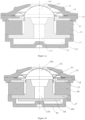
- Figure 1a shows a high-pitched loudspeaker not according to the claimed invention, comprising a panel 11, a frame 14, a front plate 15, a magnetic steel 16, and a T-iron 17, which are sequentially fixedly connected, wherein the front plate 15, the magnetic steel 16, and the T-iron 17 constitute a magnetic circuit system of the high-pitched loudspeaker, and the magnetic circuit system is an external magnetic structure.
- the diaphragm 12 is arranged on the frame 14, and the voice coil 13 is connected to the diaphragm 12, the front plate 15 and the magnetic steel 16 are arranged around the T-iron 17 and form a gap with the outer wall of the T-iron 17 for inserting the voice coil 13, the lower portion of the voice coil 13 is located in the gap, and the diaphragm 12 covers the front surface of the T-iron 17, so that a first cavity 101 is formed between the diaphragm 12, the voice coil 13, and the front surface of the T-iron 17.
- the high-pitched loudspeaker further comprises a back cover 19 fixedly connected to the back surface of the magnetic steel 16 and the T-iron 17, and the T-iron 17 is located between the diaphragm 12 and the back cover 19, and a second cavity 102 is formed between the back surface of the T-iron 17 and the back cover 19.
- the T-iron 17 is opened with a through-hole 170 extending from the front surface thereof to the back surface, and the through-hole 170 communicates the first cavity 101 and the second cavity 102 to constitute an air gap cavity of the high-pitched loudspeaker.
- Figure 1b shows another high-pitched loudspeaker of the present embodiment, which is further optimized for the high-pitched loudspeaker shown in Figure 1 .
- a damping material 18 is arranged in the air gap chamber, and the damping material 18 is a flexible gas permeable material such as polyurethane foam or foam rubber or felt.
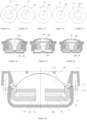
- the through-hole 170 on the T-iron 17 has various forms, and may be a circular hole, a square hole, an elliptical hole or a triangular hole, as shown in Figures 3a to 3d ; the number of the through-hole 170 is one, and may be plural, such as Figure 3e shows a circular arrangement.
- the damping material 18 is arranged in a plurality of manners, and may be arranged in the second cavity 102 and embedded between the back surface of the T-iron 17 and the back cover 19 as shown in Figure 4a ; or may be arranged in the first cavity 101 as shown in Figure 4b ; it may also be partially arranged in the second cavity 102 and another portion in the first cavity 101, as shown in Figure 4c .
- the damping material 18 covers the front and/or back of the through-hole 170.
- Figure 5a shows a high-pitched loudspeaker not according to the claimed invention, comprising a panel 21, a frame 24, a front plate 25, a magnetic steel 26 and a U-iron 27, wherein the front plate 25, the magnetic steel 26 and the U-iron 27 constitute a magnetic circuit system of the high pitch speaker, which is an internal magnetic structure.
- a diaphragm 22 is arranged on the frame 24, and a voice coil 23 is connected to the diaphragm 22.
- the outer edge of the U-iron 27 extends upward and is fixedly connected to the lower portion of the frame 24.
- the magnetic steel 26 is arranged on the U-iron 27, the front plate 25 is arranged on the magnetic steel 26, and the magnetic steel 26 and the front plate 25 are located between the diaphragm 22 and the U-iron 27.
- a gap is formed between the front plate 25 and the outer edge of the U-iron 27 for inserting the voice coil 23, the lower portion of the voice coil 23 is located in the gap, and the diaphragm 22 covers the front surface of the magnetic circuit system, so that a first cavity 201 is formed between the diaphragm 22, the voice coil 23, and the front surface of the front plate 25.
- the high-pitched loudspeaker further comprises a back cover 29 fixedly connected to the lower portion of the frame 24 such that the magnetic circuit system is located between the diaphragm 22 and the back cover 29, and a second cavity 202 is formed between the back surface of the U-iron 27 and the back cover 29.
- the front plate 25, the magnetic steel 26 and the U-iron 27 are respectively opened with through-holes 250, 260, 270 extending from the front surface thereof to the back surface, and the through-holes 250, 260, 270 communicates the first cavity 201 and the second cavity 202 to constitute an air gap cavity of the high-pitched loudspeaker.
- Figure 5b shows another high-pitched loudspeaker of the present embodiment, which is further optimized for the high-pitched loudspeaker shown in Figure 1 .
- a damping material 28 is arranged in the air gap chamber, and the damping material 28 is a flexible gas permeable material such as polyurethane foam or foam rubber or felt.
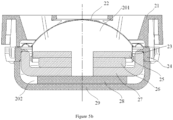
- the through-holes 250, 260, 270 on the U-iron 27, the magnetic steel 26 and the front plate 25 have various forms, and may be a circular hole, a square hole, an elliptical hole or a triangular hole, as shown in Figures 7a to 7d ; the number of each of the through-holes 250, 260, 270 is one, and may be plural, respectively, such as Figure 7e shows a circular arrangement.
- the damping material 28 is arranged in a plurality of manners, and may be arranged in the second cavity 202 and embedded between the back surface of the U-iron 27 and the back cover 29 as shown in Figure 8a ; or may be arranged in the first cavity 201 as shown in Figure 8b ; it may also be partially arranged in the second cavity 202 and another portion in the first cavity 201.
- the damping material 28 covers the front and/or back of the through-hole 170 as shown in Figure 8c .
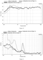
- Impedance tests of the existing ordinary high-pitched loudspeaker, the high-pitched loudspeaker shown in Figure 1a in the embodiment 1, and the high-pitched loudspeaker shown in Figure 1b in the embodiment 1 are performed to obtain high-pitched loudspeaker impedance curves, as shown in Figure 9 .
- the lightest line represents the impedance curve of the ordinary high-pitched loudspeaker
- the impedance curve of the high-pitched loudspeaker shown in Figure 1a
- the deepest line represents the impedance curve of the high-pitched loudspeaker shown in Figure 1b .
- the F0 of the ordinary high-pitched loudspeaker is at 1500 Hz and the peak value is 14 ohms;
- the F0 of the high-pitched loudspeaker shown in Figure 1a is at 950 Hz and the peak value is 12 ohms;
- the F0 of the high-pitched loudspeaker shown in Figure 1b is at 950 Hz, the peak value is 7 ohm.
- Frequency response tests of the existing ordinary high-pitched loudspeaker, the high-pitched loudspeaker shown in Figure 1a , and the high-pitched loudspeaker shown in Figure 1b in the embodiment 1 are performed to obtain high-pitched loudspeaker frequency response curves, as shown in Figure 10 .
- the lightest line represents the frequency response curve of the ordinary high-pitched loudspeaker
- the frequency response curve of the high-pitched loudspeaker shown in Figure 1a
- the deepest line represents the frequency response curve of the high-pitched loudspeaker shown in Figure 1b .
- Distortion tests of the existing ordinary high-pitched loudspeaker, the high-pitched loudspeaker shown in Figure 1a in the embodiment 1, and the high-pitched loudspeaker shown in Figure 1b are performed to obtain high-pitched loudspeaker distortion curves, as shown in Figure 11 .
- the lightest line represents the distortion curve of the ordinary high-pitched loudspeaker
- the distortion curve of the high-pitched loudspeaker shown in Figure 1a
- the deepest line represents the distortion curve of the high-pitched loudspeaker shown in Figure 1b .
- the ordinary high-pitched loudspeaker has a 1.3K Hz distortion of 7%; the high-pitched loudspeaker shown in Figure 1a has a 2.5K Hz distortion of 5.5%; the high-pitched loudspeaker shown in Figure 1b has a 1.3K Hz distortion of 3% and a 2.5 K Hz distortion of 2%.
- the F0 of the high-pitched loudspeaker is lowered, the intermediate frequency portion of the high-pitched loudspeaker is extended forward further to widen the starting frequency of the high-pitched loudspeaker.
Landscapes
- Physics & Mathematics (AREA)
- Engineering & Computer Science (AREA)
- Acoustics & Sound (AREA)
- Signal Processing (AREA)
- Health & Medical Sciences (AREA)
- Otolaryngology (AREA)
- Audible-Bandwidth Dynamoelectric Transducers Other Than Pickups (AREA)
- Obtaining Desirable Characteristics In Audible-Bandwidth Transducers (AREA)
- Diaphragms For Electromechanical Transducers (AREA)
Claims (9)
- Ein Hochtonlautsprecher, beinhaltend ein Magnetkreissystem, eine Schwingspule (13, 23) und eine mit der Schwingspule (13, 23) verbundene Membran (12, 22), wobei ein erster Hohlraum (101, 201) zwischen dem Magnetkreissystem und der Schwingspule (13, 23) und der Membran (12, 22) gebildet ist, der Hochtonlautsprecher dadurch gekennzeichnet ist, dass der Hochtonlautsprecher ferner eine hintere Abdeckung (19, 29) beinhaltet, das Magnetkreissystem zwischen der Membran (12, 22) und der hinteren Abdeckung (19, 29) angeordnet ist und ein zweiter Hohlraum (102, 202) zwischen der hinteren Abdeckung (19, 29) und dem Magnetkreissystem gebildet ist, mindestens ein Durchgangsloch (170, 250, 260, 270) in dem Magnetkreissystem geöffnet ist, und der erste Hohlraum (101, 201) und der zweite Hohlraum (102, 202) durch das mindestens eine Durchgangsloch (170, 250, 260, 270) miteinander in Kommunikation stehen, um einen Luftspalthohlraum des Hochtonlautsprechers zu bilden, der Hochtonlautsprecher ferner ein Dämpfungsmaterial (18, 28) beinhaltet, das in dem Luftspalthohlraum angeordnet ist, wobei das Dämpfungsmaterial (18, 28) Polyurethanschaum oder Schaumgummi oder Filz ist, wobei die hintere Abdeckung (19, 29) den zweiten Hohlraum auf der Rückseite des Magnetsystems umschließt.
- Hochtonlautsprecher gemäß Anspruch 1, dadurch gekennzeichnet, dass das Dämpfungsmaterial (18, 28) in dem ersten Hohlraum (101, 201) und/oder in dem zweiten Hohlraum (102, 202) des Luftspalthohlraums angeordnet ist.
- Hochtonlautsprecher gemäß Anspruch 2, dadurch gekennzeichnet, dass das Dämpfungsmaterial (18, 28) das Durchgangsloch (170, 250, 260, 270) abdeckt.
- Hochtonlautsprecher gemäß einem der vorhergehenden Ansprüche, dadurch gekennzeichnet, dass das mindestens eine Durchgangsloch (170, 250, 260, 270) ein rundes Loch, ein elliptisches Loch oder ein polygonales Loch ist.
- Hochtonlautsprecher gemäß Ansprüchen 1-3, dadurch gekennzeichnet, dass das mindestens eine Durchgangsloch (170, 250, 260, 270) ein quadratisches Loch oder ein dreieckiges Loch ist.
- Hochtonlautsprecher gemäß einem der vorhergehenden Ansprüche, dadurch gekennzeichnet, dass das Magnetkreissystem ein T-Eisen (17), einen Magnetstahl (16) und eine Frontplatte (15), die um das T-Eisen (17) herum angeordnet sind, umfasst, und dass das Durchgangsloch (170) auf dem T-Eisen (17) angeordnet ist.
- Hochtonlautsprecher gemäß Anspruch 6, dadurch gekennzeichnet, dass die Membran (12) auf einem Rahmen (14) angeordnet ist, die Frontplatte (15), der Magnetstahl (16) und das T-Eisen (17) fest mit dem Rahmen (14) verbunden sind und die hintere Abdeckung (19) fest mit dem Magnetstahl (16) verbunden ist.
- Hochtonlautsprecher gemäß einem der Ansprüche 1-5, dadurch gekennzeichnet, dass das Magnetkreissystem eine Frontplatte (25), einen Magnetstahl (26) und ein U-Eisen (27) umfasst, die hintereinander angeordnet sind, die Membran (22) auf einem Rahmen (24) angeordnet ist und ein äußerer Rand des U-Eisens (27) fest mit dem Rahmen (24) verbunden ist, sich die Frontplatte (25) und der Magnetstahl (26) zwischen der Membran (22) und dem U-Eisen (27) befinden und das mindestens eine Durchgangsloch (250, 260, 270) auf der Frontplatte (25), dem Magnetstahl (26) und dem U-Eisen (27) angeordnet ist und nacheinander die Frontplatte (25), den Magnetstahl (26) und das U-Eisen (27) durchdringt.
- Hochtonlautsprecher gemäß Anspruch 8, dadurch gekennzeichnet, dass die hintere Abdeckung (29) fest mit dem Rahmen (24) verbunden ist.
Applications Claiming Priority (2)
| Application Number | Priority Date | Filing Date | Title |
|---|---|---|---|
| CN201810455443.8A CN108347679B (zh) | 2018-05-14 | 2018-05-14 | 一种高音扬声器 |
| PCT/CN2018/106913 WO2019218564A1 (zh) | 2018-05-14 | 2018-09-21 | 一种高音扬声器 |
Publications (3)
| Publication Number | Publication Date |
|---|---|
| EP3606096A1 EP3606096A1 (de) | 2020-02-05 |
| EP3606096A4 EP3606096A4 (de) | 2020-03-04 |
| EP3606096B1 true EP3606096B1 (de) | 2024-01-31 |
Family
ID=62955523
Family Applications (1)
| Application Number | Title | Priority Date | Filing Date |
|---|---|---|---|
| EP18884847.7A Active EP3606096B1 (de) | 2018-05-14 | 2018-09-21 | Hochtonlautsprecher |
Country Status (5)
| Country | Link |
|---|---|
| US (1) | US11290822B2 (de) |
| EP (1) | EP3606096B1 (de) |
| JP (1) | JP7085553B2 (de) |
| CN (1) | CN108347679B (de) |
| WO (1) | WO2019218564A1 (de) |
Families Citing this family (4)
| Publication number | Priority date | Publication date | Assignee | Title |
|---|---|---|---|---|
| CN108347679B (zh) | 2018-05-14 | 2020-11-20 | 苏州上声电子股份有限公司 | 一种高音扬声器 |
| CN111629306B (zh) * | 2020-04-26 | 2024-06-14 | 苏州上声电子股份有限公司 | 一种高音扬声器 |
| CN112073880B (zh) * | 2020-09-02 | 2025-04-08 | 苏州上声电子股份有限公司 | 一种多音盆的小型扬声器 |
| CN118945569A (zh) * | 2024-08-07 | 2024-11-12 | 苏州上声电子股份有限公司 | 一种扩散罩及高音扬声器 |
Citations (2)
| Publication number | Priority date | Publication date | Assignee | Title |
|---|---|---|---|---|
| US5802195A (en) * | 1994-10-11 | 1998-09-01 | The United States Of America As Represented By The Administrator Of The National Aeronautics And Space Administration | High displacement solid state ferroelectric loudspeaker |
| EP3694221A1 (de) * | 2017-10-04 | 2020-08-12 | Panasonic Intellectual Property Management Co., Ltd. | Tonausgabevorrichtung, ohrhörer, hörgerät und mobiles endgerät |
Family Cites Families (18)
| Publication number | Priority date | Publication date | Assignee | Title |
|---|---|---|---|---|
| JPS5834490U (ja) * | 1981-08-27 | 1983-03-05 | 三菱電機株式会社 | スピ−カ |
| JPS6045584U (ja) * | 1983-09-05 | 1985-03-30 | パイオニア株式会社 | ド−ム・スピ−カ |
| JPH04150198A (ja) * | 1990-10-09 | 1992-05-22 | Yamaha Corp | スピーカ装置 |
| US6870941B2 (en) * | 2002-07-15 | 2005-03-22 | Glenn A. Marnie | Dipole radiating dynamic speaker |
| US20070003100A1 (en) * | 2005-07-01 | 2007-01-04 | Mei Shan Electronic Co., Ltd. | Loudspeaker structure with a lighting effect |
| US8213669B2 (en) * | 2007-08-16 | 2012-07-03 | Hi-Tech Sound System Co., Ltd. | Rotary tweeter mounting arrangement for a speaker assembly |
| CN101790891A (zh) * | 2007-09-12 | 2010-07-28 | 日本先锋公司 | 扬声器磁路、扬声器装置及扬声器磁路的制造方法 |
| CN202979242U (zh) * | 2012-11-29 | 2013-06-05 | 郁志曰 | 一种空气动力振动喇叭驱动单元及其头戴式耳机 |
| CN203378017U (zh) * | 2013-08-15 | 2014-01-01 | 廖朝红 | 一种耳机喇叭 |
| CN103945311A (zh) * | 2014-04-24 | 2014-07-23 | 中山市天键电声有限公司 | 一种新型双音圈动圈式扬声器 |
| CN105898657A (zh) * | 2014-12-18 | 2016-08-24 | 刘彦雄 | 听感零失真扬声器 |
| US9485587B1 (en) * | 2015-04-22 | 2016-11-01 | Cisco Technology, Inc. | Speaker device assembly with recoil vibration attenuating counter balance |
| CN204906712U (zh) * | 2015-07-01 | 2015-12-23 | 江西远宏科技有限公司 | 不带助听线圈的助听受话器 |
| CN107404689A (zh) * | 2016-05-18 | 2017-11-28 | 天津华伟精工电子有限公司 | 用于扬声器的t铁 |
| CN205987343U (zh) * | 2016-07-26 | 2017-02-22 | 广东佳禾声学科技有限公司 | 扬声器 |
| CN206272837U (zh) * | 2016-11-21 | 2017-06-20 | 深圳市冠旭电子股份有限公司 | 喇叭及耳机 |
| CN108347679B (zh) | 2018-05-14 | 2020-11-20 | 苏州上声电子股份有限公司 | 一种高音扬声器 |
| CN208158876U (zh) * | 2018-05-14 | 2018-11-27 | 苏州上声电子股份有限公司 | 一种高音扬声器 |
-
2018
- 2018-05-14 CN CN201810455443.8A patent/CN108347679B/zh active Active
- 2018-09-21 EP EP18884847.7A patent/EP3606096B1/de active Active
- 2018-09-21 US US16/495,782 patent/US11290822B2/en active Active
- 2018-09-21 WO PCT/CN2018/106913 patent/WO2019218564A1/zh not_active Ceased
- 2018-09-21 JP JP2019536520A patent/JP7085553B2/ja active Active
Patent Citations (2)
| Publication number | Priority date | Publication date | Assignee | Title |
|---|---|---|---|---|
| US5802195A (en) * | 1994-10-11 | 1998-09-01 | The United States Of America As Represented By The Administrator Of The National Aeronautics And Space Administration | High displacement solid state ferroelectric loudspeaker |
| EP3694221A1 (de) * | 2017-10-04 | 2020-08-12 | Panasonic Intellectual Property Management Co., Ltd. | Tonausgabevorrichtung, ohrhörer, hörgerät und mobiles endgerät |
Also Published As
| Publication number | Publication date |
|---|---|
| EP3606096A4 (de) | 2020-03-04 |
| JP7085553B2 (ja) | 2022-06-16 |
| CN108347679A (zh) | 2018-07-31 |
| EP3606096A1 (de) | 2020-02-05 |
| CN108347679B (zh) | 2020-11-20 |
| US11290822B2 (en) | 2022-03-29 |
| JP2020527296A (ja) | 2020-09-03 |
| US20210099803A1 (en) | 2021-04-01 |
| WO2019218564A1 (zh) | 2019-11-21 |
Similar Documents
| Publication | Publication Date | Title |
|---|---|---|
| US11290822B2 (en) | High-pitched loudspeaker | |
| US10889525B2 (en) | Sound absorption material preparation method, sound absorption material and filling method thereof | |
| US2766839A (en) | Loudspeaker system | |
| US20030096632A1 (en) | Speaker assembly for mobile phones | |
| US7280668B2 (en) | Ceramic metal matrix diaphragm for loudspeakers | |
| US20180206011A1 (en) | Loudspeaker module and terminal device | |
| US20250133331A1 (en) | Coaxial speaker box | |
| JP2002159083A (ja) | 低域再生用スピーカユニット | |
| CN208806972U (zh) | 扬声器 | |
| JP2023523055A (ja) | ツイーター及びカーオーディオシステム | |
| CN211321362U (zh) | 移动终端 | |
| CN112399303A (zh) | 扬声器及其音频设备、高频的尖峰频率的抑制方法 | |
| CN208158876U (zh) | 一种高音扬声器 | |
| JP4147311B2 (ja) | スピーカー | |
| CN209390245U (zh) | 一种迷宫式左右双向阻尼超薄音箱 | |
| CN207869388U (zh) | 扬声器 | |
| WO2020199132A1 (zh) | 喇叭音响 | |
| CN219999589U (zh) | 一种分频扬声器 | |
| CN2411646Y (zh) | 具有壳体外侧隔音层的音箱 | |
| JPH05130690A (ja) | スピーカ装置 | |
| CN217063924U (zh) | 二分频音箱 | |
| JP3647363B2 (ja) | 電気音響変換器 | |
| CN223843857U (zh) | 音响和汽车 | |
| CN220307368U (zh) | 微型扬声器 | |
| US12413910B2 (en) | Speaker device |
Legal Events
| Date | Code | Title | Description |
|---|---|---|---|
| STAA | Information on the status of an ep patent application or granted ep patent |
Free format text: STATUS: UNKNOWN |
|
| STAA | Information on the status of an ep patent application or granted ep patent |
Free format text: STATUS: THE INTERNATIONAL PUBLICATION HAS BEEN MADE |
|
| PUAI | Public reference made under article 153(3) epc to a published international application that has entered the european phase |
Free format text: ORIGINAL CODE: 0009012 |
|
| STAA | Information on the status of an ep patent application or granted ep patent |
Free format text: STATUS: REQUEST FOR EXAMINATION WAS MADE |
|
| 17P | Request for examination filed |
Effective date: 20190613 |
|
| AK | Designated contracting states |
Kind code of ref document: A1 Designated state(s): AL AT BE BG CH CY CZ DE DK EE ES FI FR GB GR HR HU IE IS IT LI LT LU LV MC MK MT NL NO PL PT RO RS SE SI SK SM TR |
|
| AX | Request for extension of the european patent |
Extension state: BA ME |
|
| A4 | Supplementary search report drawn up and despatched |
Effective date: 20200204 |
|
| RIC1 | Information provided on ipc code assigned before grant |
Ipc: H04R 9/06 20060101AFI20200129BHEP Ipc: H04R 9/02 20060101ALI20200129BHEP |
|
| STAA | Information on the status of an ep patent application or granted ep patent |
Free format text: STATUS: EXAMINATION IS IN PROGRESS |
|
| 17Q | First examination report despatched |
Effective date: 20210217 |
|
| DAV | Request for validation of the european patent (deleted) | ||
| DAX | Request for extension of the european patent (deleted) | ||
| GRAP | Despatch of communication of intention to grant a patent |
Free format text: ORIGINAL CODE: EPIDOSNIGR1 |
|
| STAA | Information on the status of an ep patent application or granted ep patent |
Free format text: STATUS: GRANT OF PATENT IS INTENDED |
|
| INTG | Intention to grant announced |
Effective date: 20231030 |
|
| GRAS | Grant fee paid |
Free format text: ORIGINAL CODE: EPIDOSNIGR3 |
|
| GRAA | (expected) grant |
Free format text: ORIGINAL CODE: 0009210 |
|
| STAA | Information on the status of an ep patent application or granted ep patent |
Free format text: STATUS: THE PATENT HAS BEEN GRANTED |
|
| AK | Designated contracting states |
Kind code of ref document: B1 Designated state(s): AL AT BE BG CH CY CZ DE DK EE ES FI FR GB GR HR HU IE IS IT LI LT LU LV MC MK MT NL NO PL PT RO RS SE SI SK SM TR |
|
| REG | Reference to a national code |
Ref country code: GB Ref legal event code: FG4D Ref country code: CH Ref legal event code: EP |
|
| REG | Reference to a national code |
Ref country code: DE Ref legal event code: R096 Ref document number: 602018064806 Country of ref document: DE |
|
| REG | Reference to a national code |
Ref country code: IE Ref legal event code: FG4D |
|
| P01 | Opt-out of the competence of the unified patent court (upc) registered |
Effective date: 20240126 |
|
| REG | Reference to a national code |
Ref country code: LT Ref legal event code: MG9D |
|
| REG | Reference to a national code |
Ref country code: NL Ref legal event code: MP Effective date: 20240131 |
|
| PG25 | Lapsed in a contracting state [announced via postgrant information from national office to epo] |
Ref country code: IS Free format text: LAPSE BECAUSE OF FAILURE TO SUBMIT A TRANSLATION OF THE DESCRIPTION OR TO PAY THE FEE WITHIN THE PRESCRIBED TIME-LIMIT Effective date: 20240531 |
|
| PG25 | Lapsed in a contracting state [announced via postgrant information from national office to epo] |
Ref country code: LT Free format text: LAPSE BECAUSE OF FAILURE TO SUBMIT A TRANSLATION OF THE DESCRIPTION OR TO PAY THE FEE WITHIN THE PRESCRIBED TIME-LIMIT Effective date: 20240131 |
|
| PG25 | Lapsed in a contracting state [announced via postgrant information from national office to epo] |
Ref country code: GR Free format text: LAPSE BECAUSE OF FAILURE TO SUBMIT A TRANSLATION OF THE DESCRIPTION OR TO PAY THE FEE WITHIN THE PRESCRIBED TIME-LIMIT Effective date: 20240501 |
|
| REG | Reference to a national code |
Ref country code: AT Ref legal event code: MK05 Ref document number: 1654629 Country of ref document: AT Kind code of ref document: T Effective date: 20240131 |
|
| PG25 | Lapsed in a contracting state [announced via postgrant information from national office to epo] |
Ref country code: NL Free format text: LAPSE BECAUSE OF FAILURE TO SUBMIT A TRANSLATION OF THE DESCRIPTION OR TO PAY THE FEE WITHIN THE PRESCRIBED TIME-LIMIT Effective date: 20240131 Ref country code: HR Free format text: LAPSE BECAUSE OF FAILURE TO SUBMIT A TRANSLATION OF THE DESCRIPTION OR TO PAY THE FEE WITHIN THE PRESCRIBED TIME-LIMIT Effective date: 20240131 Ref country code: RS Free format text: LAPSE BECAUSE OF FAILURE TO SUBMIT A TRANSLATION OF THE DESCRIPTION OR TO PAY THE FEE WITHIN THE PRESCRIBED TIME-LIMIT Effective date: 20240430 |
|
| PG25 | Lapsed in a contracting state [announced via postgrant information from national office to epo] |
Ref country code: ES Free format text: LAPSE BECAUSE OF FAILURE TO SUBMIT A TRANSLATION OF THE DESCRIPTION OR TO PAY THE FEE WITHIN THE PRESCRIBED TIME-LIMIT Effective date: 20240131 |
|
| PG25 | Lapsed in a contracting state [announced via postgrant information from national office to epo] |
Ref country code: AT Free format text: LAPSE BECAUSE OF FAILURE TO SUBMIT A TRANSLATION OF THE DESCRIPTION OR TO PAY THE FEE WITHIN THE PRESCRIBED TIME-LIMIT Effective date: 20240131 |
|
| PG25 | Lapsed in a contracting state [announced via postgrant information from national office to epo] |
Ref country code: RS Free format text: LAPSE BECAUSE OF FAILURE TO SUBMIT A TRANSLATION OF THE DESCRIPTION OR TO PAY THE FEE WITHIN THE PRESCRIBED TIME-LIMIT Effective date: 20240430 Ref country code: NO Free format text: LAPSE BECAUSE OF FAILURE TO SUBMIT A TRANSLATION OF THE DESCRIPTION OR TO PAY THE FEE WITHIN THE PRESCRIBED TIME-LIMIT Effective date: 20240430 Ref country code: NL Free format text: LAPSE BECAUSE OF FAILURE TO SUBMIT A TRANSLATION OF THE DESCRIPTION OR TO PAY THE FEE WITHIN THE PRESCRIBED TIME-LIMIT Effective date: 20240131 Ref country code: LT Free format text: LAPSE BECAUSE OF FAILURE TO SUBMIT A TRANSLATION OF THE DESCRIPTION OR TO PAY THE FEE WITHIN THE PRESCRIBED TIME-LIMIT Effective date: 20240131 Ref country code: IS Free format text: LAPSE BECAUSE OF FAILURE TO SUBMIT A TRANSLATION OF THE DESCRIPTION OR TO PAY THE FEE WITHIN THE PRESCRIBED TIME-LIMIT Effective date: 20240531 Ref country code: HR Free format text: LAPSE BECAUSE OF FAILURE TO SUBMIT A TRANSLATION OF THE DESCRIPTION OR TO PAY THE FEE WITHIN THE PRESCRIBED TIME-LIMIT Effective date: 20240131 Ref country code: GR Free format text: LAPSE BECAUSE OF FAILURE TO SUBMIT A TRANSLATION OF THE DESCRIPTION OR TO PAY THE FEE WITHIN THE PRESCRIBED TIME-LIMIT Effective date: 20240501 Ref country code: FI Free format text: LAPSE BECAUSE OF FAILURE TO SUBMIT A TRANSLATION OF THE DESCRIPTION OR TO PAY THE FEE WITHIN THE PRESCRIBED TIME-LIMIT Effective date: 20240131 Ref country code: ES Free format text: LAPSE BECAUSE OF FAILURE TO SUBMIT A TRANSLATION OF THE DESCRIPTION OR TO PAY THE FEE WITHIN THE PRESCRIBED TIME-LIMIT Effective date: 20240131 Ref country code: BG Free format text: LAPSE BECAUSE OF FAILURE TO SUBMIT A TRANSLATION OF THE DESCRIPTION OR TO PAY THE FEE WITHIN THE PRESCRIBED TIME-LIMIT Effective date: 20240131 Ref country code: AT Free format text: LAPSE BECAUSE OF FAILURE TO SUBMIT A TRANSLATION OF THE DESCRIPTION OR TO PAY THE FEE WITHIN THE PRESCRIBED TIME-LIMIT Effective date: 20240131 |
|
| PG25 | Lapsed in a contracting state [announced via postgrant information from national office to epo] |
Ref country code: PL Free format text: LAPSE BECAUSE OF FAILURE TO SUBMIT A TRANSLATION OF THE DESCRIPTION OR TO PAY THE FEE WITHIN THE PRESCRIBED TIME-LIMIT Effective date: 20240131 Ref country code: PT Free format text: LAPSE BECAUSE OF FAILURE TO SUBMIT A TRANSLATION OF THE DESCRIPTION OR TO PAY THE FEE WITHIN THE PRESCRIBED TIME-LIMIT Effective date: 20240531 |
|
| PG25 | Lapsed in a contracting state [announced via postgrant information from national office to epo] |
Ref country code: SE Free format text: LAPSE BECAUSE OF FAILURE TO SUBMIT A TRANSLATION OF THE DESCRIPTION OR TO PAY THE FEE WITHIN THE PRESCRIBED TIME-LIMIT Effective date: 20240131 Ref country code: PT Free format text: LAPSE BECAUSE OF FAILURE TO SUBMIT A TRANSLATION OF THE DESCRIPTION OR TO PAY THE FEE WITHIN THE PRESCRIBED TIME-LIMIT Effective date: 20240531 Ref country code: PL Free format text: LAPSE BECAUSE OF FAILURE TO SUBMIT A TRANSLATION OF THE DESCRIPTION OR TO PAY THE FEE WITHIN THE PRESCRIBED TIME-LIMIT Effective date: 20240131 Ref country code: LV Free format text: LAPSE BECAUSE OF FAILURE TO SUBMIT A TRANSLATION OF THE DESCRIPTION OR TO PAY THE FEE WITHIN THE PRESCRIBED TIME-LIMIT Effective date: 20240131 |
|
| PG25 | Lapsed in a contracting state [announced via postgrant information from national office to epo] |
Ref country code: DK Free format text: LAPSE BECAUSE OF FAILURE TO SUBMIT A TRANSLATION OF THE DESCRIPTION OR TO PAY THE FEE WITHIN THE PRESCRIBED TIME-LIMIT Effective date: 20240131 |
|
| PG25 | Lapsed in a contracting state [announced via postgrant information from national office to epo] |
Ref country code: SM Free format text: LAPSE BECAUSE OF FAILURE TO SUBMIT A TRANSLATION OF THE DESCRIPTION OR TO PAY THE FEE WITHIN THE PRESCRIBED TIME-LIMIT Effective date: 20240131 |
|
| PG25 | Lapsed in a contracting state [announced via postgrant information from national office to epo] |
Ref country code: EE Free format text: LAPSE BECAUSE OF FAILURE TO SUBMIT A TRANSLATION OF THE DESCRIPTION OR TO PAY THE FEE WITHIN THE PRESCRIBED TIME-LIMIT Effective date: 20240131 Ref country code: CZ Free format text: LAPSE BECAUSE OF FAILURE TO SUBMIT A TRANSLATION OF THE DESCRIPTION OR TO PAY THE FEE WITHIN THE PRESCRIBED TIME-LIMIT Effective date: 20240131 |
|
| PG25 | Lapsed in a contracting state [announced via postgrant information from national office to epo] |
Ref country code: SK Free format text: LAPSE BECAUSE OF FAILURE TO SUBMIT A TRANSLATION OF THE DESCRIPTION OR TO PAY THE FEE WITHIN THE PRESCRIBED TIME-LIMIT Effective date: 20240131 |
|
| PG25 | Lapsed in a contracting state [announced via postgrant information from national office to epo] |
Ref country code: SM Free format text: LAPSE BECAUSE OF FAILURE TO SUBMIT A TRANSLATION OF THE DESCRIPTION OR TO PAY THE FEE WITHIN THE PRESCRIBED TIME-LIMIT Effective date: 20240131 Ref country code: SK Free format text: LAPSE BECAUSE OF FAILURE TO SUBMIT A TRANSLATION OF THE DESCRIPTION OR TO PAY THE FEE WITHIN THE PRESCRIBED TIME-LIMIT Effective date: 20240131 Ref country code: RO Free format text: LAPSE BECAUSE OF FAILURE TO SUBMIT A TRANSLATION OF THE DESCRIPTION OR TO PAY THE FEE WITHIN THE PRESCRIBED TIME-LIMIT Effective date: 20240131 Ref country code: EE Free format text: LAPSE BECAUSE OF FAILURE TO SUBMIT A TRANSLATION OF THE DESCRIPTION OR TO PAY THE FEE WITHIN THE PRESCRIBED TIME-LIMIT Effective date: 20240131 Ref country code: DK Free format text: LAPSE BECAUSE OF FAILURE TO SUBMIT A TRANSLATION OF THE DESCRIPTION OR TO PAY THE FEE WITHIN THE PRESCRIBED TIME-LIMIT Effective date: 20240131 Ref country code: CZ Free format text: LAPSE BECAUSE OF FAILURE TO SUBMIT A TRANSLATION OF THE DESCRIPTION OR TO PAY THE FEE WITHIN THE PRESCRIBED TIME-LIMIT Effective date: 20240131 |
|
| REG | Reference to a national code |
Ref country code: DE Ref legal event code: R097 Ref document number: 602018064806 Country of ref document: DE |
|
| PLBE | No opposition filed within time limit |
Free format text: ORIGINAL CODE: 0009261 |
|
| STAA | Information on the status of an ep patent application or granted ep patent |
Free format text: STATUS: NO OPPOSITION FILED WITHIN TIME LIMIT |
|
| 26N | No opposition filed |
Effective date: 20241101 |
|
| PG25 | Lapsed in a contracting state [announced via postgrant information from national office to epo] |
Ref country code: SI Free format text: LAPSE BECAUSE OF FAILURE TO SUBMIT A TRANSLATION OF THE DESCRIPTION OR TO PAY THE FEE WITHIN THE PRESCRIBED TIME-LIMIT Effective date: 20240131 Ref country code: MC Free format text: LAPSE BECAUSE OF FAILURE TO SUBMIT A TRANSLATION OF THE DESCRIPTION OR TO PAY THE FEE WITHIN THE PRESCRIBED TIME-LIMIT Effective date: 20240131 |
|
| REG | Reference to a national code |
Ref country code: CH Ref legal event code: PL |
|
| PG25 | Lapsed in a contracting state [announced via postgrant information from national office to epo] |
Ref country code: LU Free format text: LAPSE BECAUSE OF NON-PAYMENT OF DUE FEES Effective date: 20240921 |
|
| GBPC | Gb: european patent ceased through non-payment of renewal fee |
Effective date: 20240921 |
|
| PG25 | Lapsed in a contracting state [announced via postgrant information from national office to epo] |
Ref country code: GB Free format text: LAPSE BECAUSE OF NON-PAYMENT OF DUE FEES Effective date: 20240921 |
|
| REG | Reference to a national code |
Ref country code: BE Ref legal event code: MM Effective date: 20240930 |
|
| PG25 | Lapsed in a contracting state [announced via postgrant information from national office to epo] |
Ref country code: BE Free format text: LAPSE BECAUSE OF NON-PAYMENT OF DUE FEES Effective date: 20240930 |
|
| PG25 | Lapsed in a contracting state [announced via postgrant information from national office to epo] |
Ref country code: CH Free format text: LAPSE BECAUSE OF NON-PAYMENT OF DUE FEES Effective date: 20240930 |
|
| PG25 | Lapsed in a contracting state [announced via postgrant information from national office to epo] |
Ref country code: IE Free format text: LAPSE BECAUSE OF NON-PAYMENT OF DUE FEES Effective date: 20240921 |
|
| PGFP | Annual fee paid to national office [announced via postgrant information from national office to epo] |
Ref country code: IT Payment date: 20250923 Year of fee payment: 8 |
|
| PGFP | Annual fee paid to national office [announced via postgrant information from national office to epo] |
Ref country code: FR Payment date: 20250929 Year of fee payment: 8 |
|
| PGFP | Annual fee paid to national office [announced via postgrant information from national office to epo] |
Ref country code: DE Payment date: 20250929 Year of fee payment: 8 |
|
| PG25 | Lapsed in a contracting state [announced via postgrant information from national office to epo] |
Ref country code: CY Free format text: LAPSE BECAUSE OF FAILURE TO SUBMIT A TRANSLATION OF THE DESCRIPTION OR TO PAY THE FEE WITHIN THE PRESCRIBED TIME-LIMIT; INVALID AB INITIO Effective date: 20180921 |
|
| PG25 | Lapsed in a contracting state [announced via postgrant information from national office to epo] |
Ref country code: HU Free format text: LAPSE BECAUSE OF FAILURE TO SUBMIT A TRANSLATION OF THE DESCRIPTION OR TO PAY THE FEE WITHIN THE PRESCRIBED TIME-LIMIT; INVALID AB INITIO Effective date: 20180921 |