EP3605658B1 - Verfahren und vorrichtung zum entwerfen einer flexiblen kupfersammelschiene einer leistungsbatterie - Google Patents
Verfahren und vorrichtung zum entwerfen einer flexiblen kupfersammelschiene einer leistungsbatterie Download PDFInfo
- Publication number
- EP3605658B1 EP3605658B1 EP19174680.9A EP19174680A EP3605658B1 EP 3605658 B1 EP3605658 B1 EP 3605658B1 EP 19174680 A EP19174680 A EP 19174680A EP 3605658 B1 EP3605658 B1 EP 3605658B1
- Authority
- EP
- European Patent Office
- Prior art keywords
- battery module
- connection portion
- battery
- flexible copper
- copper busbar
- Prior art date
- Legal status (The legal status is an assumption and is not a legal conclusion. Google has not performed a legal analysis and makes no representation as to the accuracy of the status listed.)
- Active
Links
Images


Classifications
-
- G—PHYSICS
- G06—COMPUTING OR CALCULATING; COUNTING
- G06F—ELECTRIC DIGITAL DATA PROCESSING
- G06F30/00—Computer-aided design [CAD]
- G06F30/20—Design optimisation, verification or simulation
- G06F30/23—Design optimisation, verification or simulation using finite element methods [FEM] or finite difference methods [FDM]
-
- H—ELECTRICITY
- H01—ELECTRIC ELEMENTS
- H01M—PROCESSES OR MEANS, e.g. BATTERIES, FOR THE DIRECT CONVERSION OF CHEMICAL ENERGY INTO ELECTRICAL ENERGY
- H01M50/00—Constructional details or processes of manufacture of the non-active parts of electrochemical cells other than fuel cells, e.g. hybrid cells
- H01M50/50—Current conducting connections for cells or batteries
- H01M50/502—Interconnectors for connecting terminals of adjacent batteries; Interconnectors for connecting cells outside a battery casing
- H01M50/503—Interconnectors for connecting terminals of adjacent batteries; Interconnectors for connecting cells outside a battery casing characterised by the shape of the interconnectors
-
- H—ELECTRICITY
- H01—ELECTRIC ELEMENTS
- H01M—PROCESSES OR MEANS, e.g. BATTERIES, FOR THE DIRECT CONVERSION OF CHEMICAL ENERGY INTO ELECTRICAL ENERGY
- H01M50/00—Constructional details or processes of manufacture of the non-active parts of electrochemical cells other than fuel cells, e.g. hybrid cells
- H01M50/50—Current conducting connections for cells or batteries
- H01M50/502—Interconnectors for connecting terminals of adjacent batteries; Interconnectors for connecting cells outside a battery casing
- H01M50/505—Interconnectors for connecting terminals of adjacent batteries; Interconnectors for connecting cells outside a battery casing comprising a single busbar
-
- H—ELECTRICITY
- H01—ELECTRIC ELEMENTS
- H01M—PROCESSES OR MEANS, e.g. BATTERIES, FOR THE DIRECT CONVERSION OF CHEMICAL ENERGY INTO ELECTRICAL ENERGY
- H01M50/00—Constructional details or processes of manufacture of the non-active parts of electrochemical cells other than fuel cells, e.g. hybrid cells
- H01M50/50—Current conducting connections for cells or batteries
- H01M50/502—Interconnectors for connecting terminals of adjacent batteries; Interconnectors for connecting cells outside a battery casing
- H01M50/521—Interconnectors for connecting terminals of adjacent batteries; Interconnectors for connecting cells outside a battery casing characterised by the material
- H01M50/522—Inorganic material
-
- H—ELECTRICITY
- H01—ELECTRIC ELEMENTS
- H01M—PROCESSES OR MEANS, e.g. BATTERIES, FOR THE DIRECT CONVERSION OF CHEMICAL ENERGY INTO ELECTRICAL ENERGY
- H01M2220/00—Batteries for particular applications
-
- Y—GENERAL TAGGING OF NEW TECHNOLOGICAL DEVELOPMENTS; GENERAL TAGGING OF CROSS-SECTIONAL TECHNOLOGIES SPANNING OVER SEVERAL SECTIONS OF THE IPC; TECHNICAL SUBJECTS COVERED BY FORMER USPC CROSS-REFERENCE ART COLLECTIONS [XRACs] AND DIGESTS
- Y02—TECHNOLOGIES OR APPLICATIONS FOR MITIGATION OR ADAPTATION AGAINST CLIMATE CHANGE
- Y02E—REDUCTION OF GREENHOUSE GAS [GHG] EMISSIONS, RELATED TO ENERGY GENERATION, TRANSMISSION OR DISTRIBUTION
- Y02E60/00—Enabling technologies; Technologies with a potential or indirect contribution to GHG emissions mitigation
- Y02E60/10—Energy storage using batteries
Definitions
- the invention relates to the field of power battery, and in particular relates to a method and apparatus for designing a flexible copper busbar of a power battery.
- a power battery is formed by connecting a plurality of battery modules in series.
- Property of the power battery is directly affected by the design of electric connection structures between battery modules.
- strict requirements are imposed on reliability, electric current carrying capacity and contact resistance between battery modules.
- flexible copper busbars have become one of the most popular electric connection structures between battery modules.
- CAE analysis generally comprises to analyze whether the stress in the flexible copper busbar exceeds a predetermined value in working conditions, such as when the power battery is subjected to vibration or shock.
- CAE modeling faces a big difficulty since the flexible copper busbar is formed by laminating multi layers of thin sheet copper.
- existing flexible copper busbar has a flat plate structure so the flexible copper busbar is easy to be stretched in harsh working conditions, which may further result in decreasing in fatigue life of the flexible copper busbar and changing in contact resistance.
- US 2018/097322 A1 discloses a flexible bus bar having at least three rigid sections and at least two flexible sections.
- CN 107423499 A discloses a system for improving anti-vibration performance of a battery pack.
- the invention provides a method and apparatus for designing a flexible copper busbar of a power battery, with an object of increasing the power battery designing efficiency and ensuring that there is no force transmission in the flexible copper busbar in harsh working conditions so that fatigue life of the flexible copper busbar and stability of contact resistance can be increased.
- a method for designing a flexible copper busbar of a power battery comprising a first connection portion (11), a second connection portion (12), and a convex portion (13) connected between the first connection portion (11) and the second connection portion (12); wherein the first connection portion (11) comprises a first connection hole, and the first connection portion is connected with the first battery module via the first connection hole; and wherein the second connection portion (12) comprises a second connection hole, and the second connection portion is connected with the second battery module via the second connection hole, the first battery module and the second battery module being adjacent to each other; the method being characterized in comprising:
- the safety factor is 2.
- An apparatus for designing a flexible copper busbar of a power battery comprising a first connection portion (11), a second connection portion (12), and a convex portion (13) connected between the first connection portion (11) and the second connection portion (12); wherein the first connection portion (11) comprises a first connection hole, and the first connection portion is connected with the first battery module via the first connection hole; and wherein the second connection portion (12) comprises a second connection hole, and the second connection portion is connected with the second battery module via the second connection hole, the first battery module and the second battery module being adjacent to each other; the apparatus being characterized in comprising:
- the safety factor is 2.
- the above technical solutions provide a flexible copper busbar which comprises a first connection portion (11), a second connection portion (12), and a convex portion (13) connected between the first connection portion (11) and the second connection portion (12).
- the convex portion (13) is stretched to become straightened under a force to become straightened, stress is distributed uniformly without stress concentration, and there is no force transmission. Fatigue life and contact resistance stability of the flexible copper busbar can be increased.
- the above technical solutions provide a method and apparatus for designing the above flexible copper busbar, in which, by analyzing the maximum space between first and second battery modules which are connected with opposite ends of the flexible copper busbar and then determining the total length of the flexible copper busbar, a procedure of investigating the stress by modeling the flexible copper busbar is avoided, and power battery designing efficiency can be increased.
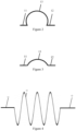
- FIG. 1 An example of a flexible copper busbar is illustrated in Figure 1 .
- the structure of the flexible copper busbar comprises: a first connection portion 11, a second connection portion 12, and a convex portion 13 connected between the first connection portion 11 and the second connection portion 12.
- the convex portion 13 shown in the present example particularly has a shape of a semi-circle.
- the convex portion 13 may alternatively have a shape of other types of arc, such as that shown in Figure 2 and Figure 3 , or have a shape of waves, such as that shown in Figure 4 and Figure 5 .
- the first connection portion 11 comprises a first connection hole and is connected to a first battery module 21 via the first connection hole.
- the second connection portion 12 comprises a second connection hole and is connected to the second battery module 22 via the second connection hole, the first battery module 21 and the second battery module 22 being adjacent to each other.
- connection portion between the first connection portion 11 and the second connection portion 12 By configuring the connection portion between the first connection portion 11 and the second connection portion 12 as the convex portion 13, the convex portion 13 is stretched to become straightened under a force in harsh working conditions, stress is distributed uniformly without stress concentration, and there is no force transmission. Fatigue life and contact resistance stability of the flexible copper busbar can be increased.
- An embodiment provides a method for designing the above described flexible copper busbar. As illustrated in Figure 6 , the method comprises the steps described below.
- S 11 performing mode analysis to a previously established finite element grid model of a power battery to find a direction with a minimum rigidity in the finite element grid model of the power battery.
- a finite element grid model of the power battery is previously defined in "Hypermesh" based on a three-dimensional model of the power battery.
- the finite element grid model of the power battery is a finite element model which reflects real structures of a battery pack casing, a battery module, a high voltage box and a BMS, both the mass of the flexible copper busbar and the mass of the harness being added into the battery module. That is to say, in the finite element grid model of the power battery, the structures of the harness and the flexible copper busbar are omitted so that modeling analysis to the flexible copper busbar is avoided, and the masses of the harness and the flexible copper busbar are given to the battery module so that the result of the analysis is more approximate to the real condition.
- the mass of the battery module equals to the real total mass of the battery module, the harness and the flexible copper busbar; the structure of the battery module has undergone simplification treatment, and the simplified battery module model comprises a simplified integer of end plates, side plates and all battery cells.
- "tie” treatment is used in the finite element grid model of the power battery; for bolted or welded connections in the battery pack, "rigid unit connection” is used in the finite element grid model of the power battery; for the welded connections in the battery pack, “seam” treatment may alternatively be used in the finite element grid model of the power battery.
- Mode analysis to the finite element grid model of the power battery is performed by using a finite element structure analysis software, such as "optistruct", with full restrains being applied to the mounting point of the power battery, the mode analysis frequency being in the range of 0-200 Hz, and participation factors and effective masses in the directions of 6 DOFs (degrees of freedom) being output.
- a finite element structure analysis software such as "optistruct”
- the mode analysis frequency being in the range of 0-200 Hz
- participation factors and effective masses in the directions of 6 DOFs (degrees of freedom) being output As shown in Figure 6 , the power battery is mounted to a vehicle, the driving direction is X-direction, the height direction is Z-direction, and the transverse direction of the vehicle is Y-direction. Basic frequencies in all the directions are determined based on results of the mode analysis.
- the effective mass in Z-direction reaches its maximum level at 20 Hz, so the basic frequency in Z-direction is 20 Hz; it is found by means of analysis that the effective mass in Y-direction reaches its maximum level at 30 Hz, so the basic frequency in Y-direction is 30 Hz; it is found by means of analysis that the effective mass in X-direction reaches its maximum level at 40 Hz, so the basic frequency in X-direction is 40 Hz. Since Z-direction has a lowest basic frequency, the power battery is considered to have a weakest rigidity in Z-direction, that is, the direction with a minimum rigidity in the finite element grid model of the power battery is Z-direction.
- the signal of the extreme mechanical shock working condition corresponds to data presented when a maximum space is created between the first battery module 21 and the second battery module 22.
- the signal of the extreme mechanical shock working condition is an acceleration of (25 g, 15 ms).
- 25 g means 25 times of the acceleration of gravity
- 15 ms represents a half-chord wave having a pulse width of 15 ms.
- a finite element analysis software such as "ls-dyna"
- DOFs in all 5 directions except Z-direction are restrained
- the signal of (25g, 15ms) is applied in Z-direction to the mounting point of the power battery, and corresponding relation of the space between the first battery module 21 and the second battery module 22 vs. time is obtained; and then the maximum space L1 between first battery module 21 and second battery module 22 can be obtained.
- Existing mode analysis methods and mechanical shock analysis methods can all be used in the present embodiment, and the invention imposes no limitation to concrete mode analysis procedures and mechanical shock analysis procedures.
- the total length L4 is the distance between the opposite ends of the flexible copper busbar in the condition that the flexible copper busbar is under a pulling force and the convex portion 13 is stretched to become straightened.
- L3 is the distance between the opposite ends of the flexible copper busbar in the condition that the flexible copper busbar is free of any pulling force.
- the value of the safety factor is selected from a range of [1, 3]. In a particular embodiment, the safety factor is selected to be 2, as a result of which, fatigue life and contact resistance stability of the flexible copper busbar can be increased on one hand, and there is little material waste on the other hand.
- An embodiment further provides an apparatus for designing the above described flexible copper busbar.
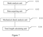
- the apparatus comprises: a mode analysis unit U11, a data acquiring unit U12, a mechanical shock analysis unit U13 and a total length calculating unit U14.
- the mode analysis unit U11 is configured to perform mode analysis to a previously established finite element grid model of a power battery to find a direction with a minimum rigidity in the finite element grid model of the power battery, the finite element grid model of the power battery being a finite element model in which real structures of a battery pack casing, battery modules, a high voltage box and a BMS are reflected, and the mass of the flexible copper busbar and the mass of the harness being added to the battery module.
- the data acquiring unit U12 is configured to obtain a signal of an extreme mechanical shock working condition, the signal of the extreme mechanical shock working condition corresponding to data presented when a maximum space is created between the first battery module and the second battery module.
- the mechanical shock analysis unit U13 is configured to apply the signal of the extreme mechanical shock working condition in the direction with the minimum rigidity in the finite element grid model of the power battery to perform mechanical shock analysis in which the maximum space between the first battery module and the second battery module is obtained.
- the total length calculating unit U14 is configured to subtract an initial space between the first battery module and the second battery module from the maximum space, to multiply the result thus obtained by a predetermined safety factor, and then to add an initial space between opposite ends of the flexible copper busbar to the result that has been multiplied with the safety factor so that the total length of the flexible copper busbar is obtained, the value of the safety factor being selected from a range of [1, 3].
- the apparatus embodiment considering that it corresponds substantially to the method embodiment, the features of the apparatus can be understood with reference to the description portion made to the method embodiment.
- the apparatus embodiment described above is only illustrative, in which units described as individual elements may be either physically separated from each other or not, and components shown as a unit may either form a physical unit or not, that is to say, these components may be arranged at one location or distributed into a plurality of network units.
- some or all the modules of the units can be selected to be used according to real requirements. This can be appreciated and implemented by those skilled in the art without doing inventive work.
Landscapes
- Chemical & Material Sciences (AREA)
- General Chemical & Material Sciences (AREA)
- Chemical Kinetics & Catalysis (AREA)
- Electrochemistry (AREA)
- Engineering & Computer Science (AREA)
- Inorganic Chemistry (AREA)
- Physics & Mathematics (AREA)
- Theoretical Computer Science (AREA)
- Computer Hardware Design (AREA)
- Evolutionary Computation (AREA)
- Geometry (AREA)
- General Engineering & Computer Science (AREA)
- General Physics & Mathematics (AREA)
- Connection Of Batteries Or Terminals (AREA)
Claims (4)
- Verfahren zum Entwerfen einer flexiblen Kupfersammelschiene einer Leistungsbatterie, wobei die flexible Kupfersammelschiene einen ersten Verbindungsabschnitt (11), einen zweiten Verbindungsabschnitt (12) und einen konvexen Abschnitt (13) umfasst, der zwischen dem ersten Verbindungsabschnitt (11) und dem zweiten Verbindungsabschnitt (12) angeschlossen ist; wobei der erste Verbindungsabschnitt (11) ein erstes Verbindungsloch umfasst und der erste Verbindungsabschnitt über das erste Verbindungsloch mit dem ersten Batteriemodul verbunden ist; und wobei der zweite Verbindungsabschnitt (12) ein zweites Verbindungsloch umfasst und der zweite Verbindungsabschnitt über das zweite Verbindungsloch mit dem zweiten Batteriemodul verbunden ist, wobei das erste Batteriemodul und das zweite Batteriemodul nebeneinander liegen;
wobei das Verfahren dadurch gekennzeichnet ist, dass es umfasst:Durchführen einer Modusanalyse an einem zuvor hergestellten Finite-Elemente-Gittermodell der Leistungsbatterie, um eine Richtung mit minimaler Steifigkeit im Finite-Elemente-Gittermodell der Leistungsbatterie zu finden, wobei das Finite-Elemente-Gittermodell der Leistungsbatterie ein Finite-Elemente-Modell ist, in dem reale Strukturen von einem Batteriepackgehäuse, Batteriemodulen, einer Hochspannungsbox und eines BMS widergespiegelt sind und sowohl die Masse der flexiblen Kupfersammelschiene als auch die Masse eines Kabelbaums der Leistungsbatterie in das Batteriemodul hinzugefügt werden;Erhalten eines Signals eines Betriebszustands mit extremen mechanischen Stößen, wobei das Signal des Betriebszustands mit extremen mechanischen Stößen Daten entspricht, die vorliegen, wenn zwischen dem ersten Batteriemodul und dem zweiten Batteriemodul ein maximaler Abstand geschaffen wird;Anwenden des Signals des Betriebszustands mit extremen mechanischen Stößen in der Richtung mit der minimalen Steifigkeit im Finite-Elemente-Gittermodell der Leistungsbatterie, um eine Analyse mechanischer Stöße durchzuführen, bei der der maximale Abstand zwischen dem ersten Batteriemodul und dem zweiten Batteriemodul erhalten wird; undErhalten der Gesamtlänge der flexiblen Kupfersammelschiene, indem zunächst ein Anfangsabstand zwischen dem ersten Batteriemodul und dem zweiten Batteriemodul vom maximalen Abstand abgezogen wird, dann das so erhaltene Ergebnis mit einem vorgegebenen Sicherheitsfaktor multipliziert wird und dann ein Anfangsabstand zwischen den gegenüberliegenden Enden der flexiblen Kupfersammelschiene zu dem mit dem Sicherheitsfaktor multiplizierten Ergebnis addiert wird, wobei der Wert des Sicherheitsfaktors aus einem Bereich von 1 bis 3 ausgewählt wird. - Verfahren nach Anspruch 1, dadurch gekennzeichnet, dass der Sicherheitsfaktor 2 beträgt.
- Vorrichtung zum Entwerfen einer flexiblen Kupfersammelschiene einer Leistungsbatterie, wobei die flexible Kupfersammelschiene einen ersten Verbindungsabschnitt (11), einen zweiten Verbindungsabschnitt (12) und einen konvexen Abschnitt (13) umfasst, der zwischen dem ersten Verbindungsabschnitt (11) und dem zweiten Verbindungsabschnitt (12) angeschlossen ist; wobei der erste Verbindungsabschnitt (11) ein erstes Verbindungsloch umfasst und der erste Verbindungsabschnitt über das erste Verbindungsloch mit dem ersten Batteriemodul verbunden ist; und wobei der zweite Verbindungsabschnitt (12) ein zweites Verbindungsloch umfasst und der zweite Verbindungsabschnitt über das zweite Verbindungsloch mit dem zweiten Batteriemodul verbunden ist, wobei das erste Batteriemodul und das zweite Batteriemodul nebeneinander liegen;
wobei die Vorrichtung dadurch gekennzeichnet ist, dass sie umfasst:eine Modusanalyseeinheit, die dazu konfiguriert ist, eine Modusanalyse an einem zuvor hergestellten Finite-Elemente-Gittermodell der Leistungsbatterie durchzuführen, um eine Richtung mit minimaler Steifigkeit im Finite-Elemente-Gittermodell der Leistungsbatterie zu finden, wobei das Finite-Elemente-Gittermodell der Leistungsbatterie ein Finite-Elemente-Modell ist, in dem reale Strukturen von einem Batteriepackgehäuse, Batteriemodulen, einer Hochspannungsbox und eines BMS widergespiegelt sind und sowohl die Masse der flexiblen Kupfersammelschiene als auch die Masse eines Kabelbaums der Leistungsbatterie in das Batteriemodul hinzugefügt werden;eine Datenerfassungseinheit, die dazu konfiguriert ist, ein Signal eines Betriebszustands mit extremen mechanischen Stößen zu erhalten, wobei das Signal des Betriebszustands mit extremen mechanischen Stößen Daten entspricht, die vorliegen, wenn zwischen dem ersten Batteriemodul und dem zweiten Batteriemodul ein maximaler Abstand geschaffen wird;eine Analyseeinheit für mechanische Stöße, die dazu konfiguriert ist, das Signal des Betriebszustands mit extremen mechanischen Stößen in der Richtung mit der minimalen Steifigkeit im Finite-Elemente-Gittermodell der Leistungsbatterie anzuwenden, um eine Analyse mechanischer Stöße durchzuführen, bei der der maximale Abstand zwischen dem ersten Batteriemodul und dem zweiten Batteriemodul erhalten wird; undeine Gesamtlängenberechnungseinheit, die dazu konfiguriert ist, ein Anfangsabstand zwischen dem ersten Batteriemodul und dem zweiten Batteriemodul vom maximalen Abstand abzuziehen, das so erhaltene Ergebnis mit einem vorgegebenen Sicherheitsfaktor zu multiplizieren und dann ein Anfangsabstand zwischen den gegenüberliegenden Enden der flexiblen Kupfersammelschiene zu dem mit dem Sicherheitsfaktor multiplizierten Ergebnis zu addieren, sodass die Gesamtlänge der flexiblen Kupfersammelschiene erhalten wird, wobei der Wert des Sicherheitsfaktors aus einem Bereich von 1 bis 3 ausgewählt wird. - Vorrichtung nach Anspruch 3, dadurch gekennzeichnet, dass der Sicherheitsfaktor 2 beträgt.
Applications Claiming Priority (1)
| Application Number | Priority Date | Filing Date | Title |
|---|---|---|---|
| CN201810871078.9A CN110854348B (zh) | 2018-08-02 | 2018-08-02 | 一种软铜排、动力电池的软铜排的设计方法及装置 |
Publications (2)
| Publication Number | Publication Date |
|---|---|
| EP3605658A1 EP3605658A1 (de) | 2020-02-05 |
| EP3605658B1 true EP3605658B1 (de) | 2025-01-15 |
Family
ID=66597503
Family Applications (1)
| Application Number | Title | Priority Date | Filing Date |
|---|---|---|---|
| EP19174680.9A Active EP3605658B1 (de) | 2018-08-02 | 2019-05-15 | Verfahren und vorrichtung zum entwerfen einer flexiblen kupfersammelschiene einer leistungsbatterie |
Country Status (2)
| Country | Link |
|---|---|
| EP (1) | EP3605658B1 (de) |
| CN (1) | CN110854348B (de) |
Families Citing this family (6)
| Publication number | Priority date | Publication date | Assignee | Title |
|---|---|---|---|---|
| KR102194843B1 (ko) * | 2017-09-07 | 2020-12-23 | 주식회사 엘지화학 | 모노 프레임의 구조해석 툴 및 모노 프레임 설계방법 |
| JP7661937B2 (ja) * | 2022-06-28 | 2025-04-15 | トヨタ自動車株式会社 | 車両電源装置 |
| CN116227295B (zh) * | 2023-03-10 | 2023-11-28 | 宁夏宝丰昱能科技有限公司 | 电池包有限元建模方法、装置、计算机设备及存储介质 |
| CN118399123B (zh) * | 2024-06-28 | 2024-08-23 | 湖南蠡庄智能科技有限公司 | 一种具有锁紧结构的模组连接铜排 |
| CN119044782B (zh) * | 2024-09-10 | 2025-09-23 | 孝感楚能新能源创新科技有限公司 | 一种电池包铜排寿命预测方法和装置 |
| CN119803218B (zh) * | 2024-12-06 | 2025-10-28 | 中航西安飞机工业集团股份有限公司 | 一种飞机零件圆弧检测装置及其稳定性评价方法 |
Family Cites Families (10)
| Publication number | Priority date | Publication date | Assignee | Title |
|---|---|---|---|---|
| CN200953386Y (zh) * | 2006-09-14 | 2007-09-26 | 比亚迪股份有限公司 | 一种用于连接单元电池的连接件 |
| CN102254059B (zh) * | 2011-05-09 | 2014-01-22 | 北京信息科技大学 | 一种惯性测量单元外壳结构的优化设计方法 |
| CN203013993U (zh) * | 2012-12-07 | 2013-06-19 | 安费诺-泰姆斯(常州)通讯设备有限公司 | 用于电连接的柔性软铜排组件 |
| CN102945711B (zh) * | 2012-12-07 | 2015-05-13 | 安费诺-泰姆斯(常州)通讯设备有限公司 | 用于电连接的柔性软铜排组件的制备方法 |
| CN203406359U (zh) * | 2013-08-09 | 2014-01-22 | 奇瑞汽车股份有限公司 | 一种电动汽车动力电池的连接结构 |
| JP2015099759A (ja) * | 2013-11-20 | 2015-05-28 | 株式会社東芝 | 組電池用バスバーおよび組電池 |
| CN103824991B (zh) * | 2014-03-13 | 2016-08-17 | 苏州易美新思新能源科技有限公司 | 一种用于电池包的叠加式软连接结构 |
| US20180097322A1 (en) * | 2016-09-30 | 2018-04-05 | Faraday&Future Inc. | Flexible bus bar |
| CN107423499A (zh) * | 2017-07-17 | 2017-12-01 | 江苏银基烯碳能源科技有限公司 | 提高电池包抗振性能的系统及方法 |
| CN107665748B (zh) * | 2017-10-31 | 2024-02-23 | 深圳巴斯巴科技发展有限公司 | 一种软铜排端镀结构及端镀工艺 |
-
2018
- 2018-08-02 CN CN201810871078.9A patent/CN110854348B/zh not_active Expired - Fee Related
-
2019
- 2019-05-15 EP EP19174680.9A patent/EP3605658B1/de active Active
Also Published As
| Publication number | Publication date |
|---|---|
| CN110854348B (zh) | 2022-05-10 |
| EP3605658A1 (de) | 2020-02-05 |
| CN110854348A (zh) | 2020-02-28 |
Similar Documents
| Publication | Publication Date | Title |
|---|---|---|
| EP3605658B1 (de) | Verfahren und vorrichtung zum entwerfen einer flexiblen kupfersammelschiene einer leistungsbatterie | |
| US9945098B2 (en) | Shovel including power storage device with housing having coolant flow path | |
| CN211320199U (zh) | 采样组件、电池模块、电池组及装置 | |
| CN109580151A (zh) | 一种基于cae的新能源汽车电池包的振动疲劳性模拟测试方法 | |
| CN207425965U (zh) | 一种电池包壳体 | |
| DE102014222694A1 (de) | Vorrichtung und Verfahren zur Erkennung eines Kontaktfehlers bei einer Batteriezelle sowie Batteriemodul, Batterie, Batteriesystem, Fahrzeug, Computerprogramm und Computerprogrammprodukt | |
| Arab et al. | Free vibration response of internally-thickness-tapered laminated composite square plates based on an energy method | |
| WO2010131085A2 (en) | Fastening structure of power unit | |
| Ruan et al. | Simulation and optimization of a new energy vehicle power battery pack structure | |
| CN210040349U (zh) | 电池模组的模组外壳、电池模组及动力电池 | |
| CN221861839U (zh) | 电池装置及用电装置 | |
| Bala et al. | Design and optimization of battery housing in electric cars | |
| CN219873946U (zh) | 一种电池包及新能源汽车 | |
| CN107271361A (zh) | 电池模组强度预估方法 | |
| CN116579197A (zh) | 一种提升电池包随机振动疲劳性能的方法及系统 | |
| Zhang et al. | Lightweight threshing rack under multisource excitation based on modal optimization method | |
| CN104979866A (zh) | 用于大数量电池单元监测的输电线通信 | |
| CN117648754A (zh) | 一种电池包框架的构建方法、装置、电子设备及介质 | |
| Keränen | Considering vibration in hybrid and electric non-road mobile machinery battery systems | |
| Lu et al. | Modal analysis and optimization of electric vehicle’s fast-swap battery box | |
| CN209843889U (zh) | 变形监控板以及电池包 | |
| JP3888283B2 (ja) | バッテリーモジュール | |
| CN206312983U (zh) | 电池箱 | |
| CN222191048U (zh) | 一种电池包框架结构、电池包箱体及车辆 | |
| Yang et al. | COLLISION SIMULATION AND LIGHTWEIGHTING RESEARCH ON BATTERY PACK STRUCTURE OF NEW ENERGY VEHICLES. |
Legal Events
| Date | Code | Title | Description |
|---|---|---|---|
| PUAI | Public reference made under article 153(3) epc to a published international application that has entered the european phase |
Free format text: ORIGINAL CODE: 0009012 |
|
| STAA | Information on the status of an ep patent application or granted ep patent |
Free format text: STATUS: THE APPLICATION HAS BEEN PUBLISHED |
|
| AK | Designated contracting states |
Kind code of ref document: A1 Designated state(s): AL AT BE BG CH CY CZ DE DK EE ES FI FR GB GR HR HU IE IS IT LI LT LU LV MC MK MT NL NO PL PT RO RS SE SI SK SM TR |
|
| AX | Request for extension of the european patent |
Extension state: BA ME |
|
| STAA | Information on the status of an ep patent application or granted ep patent |
Free format text: STATUS: REQUEST FOR EXAMINATION WAS MADE |
|
| 17P | Request for examination filed |
Effective date: 20200716 |
|
| RBV | Designated contracting states (corrected) |
Designated state(s): AL AT BE BG CH CY CZ DE DK EE ES FI FR GB GR HR HU IE IS IT LI LT LU LV MC MK MT NL NO PL PT RO RS SE SI SK SM TR |
|
| STAA | Information on the status of an ep patent application or granted ep patent |
Free format text: STATUS: EXAMINATION IS IN PROGRESS |
|
| 17Q | First examination report despatched |
Effective date: 20230207 |
|
| REG | Reference to a national code |
Ref country code: DE Ref legal event code: R079 Free format text: PREVIOUS MAIN CLASS: H01M0002200000 Ipc: G06F0030230000 Ref document number: 602019064804 Country of ref document: DE |
|
| RIC1 | Information provided on ipc code assigned before grant |
Ipc: H01M 50/522 20210101ALI20240723BHEP Ipc: H01M 50/505 20210101ALI20240723BHEP Ipc: H01M 50/503 20210101ALI20240723BHEP Ipc: G06F 30/23 20200101AFI20240723BHEP |
|
| GRAP | Despatch of communication of intention to grant a patent |
Free format text: ORIGINAL CODE: EPIDOSNIGR1 |
|
| STAA | Information on the status of an ep patent application or granted ep patent |
Free format text: STATUS: GRANT OF PATENT IS INTENDED |
|
| INTG | Intention to grant announced |
Effective date: 20240927 |
|
| GRAS | Grant fee paid |
Free format text: ORIGINAL CODE: EPIDOSNIGR3 |
|
| GRAA | (expected) grant |
Free format text: ORIGINAL CODE: 0009210 |
|
| STAA | Information on the status of an ep patent application or granted ep patent |
Free format text: STATUS: THE PATENT HAS BEEN GRANTED |
|
| AK | Designated contracting states |
Kind code of ref document: B1 Designated state(s): AL AT BE BG CH CY CZ DE DK EE ES FI FR GB GR HR HU IE IS IT LI LT LU LV MC MK MT NL NO PL PT RO RS SE SI SK SM TR |
|
| REG | Reference to a national code |
Ref country code: CH Ref legal event code: EP Ref country code: GB Ref legal event code: FG4D |
|
| REG | Reference to a national code |
Ref country code: DE Ref legal event code: R096 Ref document number: 602019064804 Country of ref document: DE |
|
| REG | Reference to a national code |
Ref country code: IE Ref legal event code: FG4D |
|
| REG | Reference to a national code |
Ref country code: NL Ref legal event code: MP Effective date: 20250115 |
|
| PG25 | Lapsed in a contracting state [announced via postgrant information from national office to epo] |
Ref country code: NL Free format text: LAPSE BECAUSE OF FAILURE TO SUBMIT A TRANSLATION OF THE DESCRIPTION OR TO PAY THE FEE WITHIN THE PRESCRIBED TIME-LIMIT Effective date: 20250115 |
|
| PG25 | Lapsed in a contracting state [announced via postgrant information from national office to epo] |
Ref country code: RS Free format text: LAPSE BECAUSE OF FAILURE TO SUBMIT A TRANSLATION OF THE DESCRIPTION OR TO PAY THE FEE WITHIN THE PRESCRIBED TIME-LIMIT Effective date: 20250415 |
|
| PG25 | Lapsed in a contracting state [announced via postgrant information from national office to epo] |
Ref country code: FI Free format text: LAPSE BECAUSE OF FAILURE TO SUBMIT A TRANSLATION OF THE DESCRIPTION OR TO PAY THE FEE WITHIN THE PRESCRIBED TIME-LIMIT Effective date: 20250115 |
|
| PG25 | Lapsed in a contracting state [announced via postgrant information from national office to epo] |
Ref country code: PL Free format text: LAPSE BECAUSE OF FAILURE TO SUBMIT A TRANSLATION OF THE DESCRIPTION OR TO PAY THE FEE WITHIN THE PRESCRIBED TIME-LIMIT Effective date: 20250115 |
|
| PG25 | Lapsed in a contracting state [announced via postgrant information from national office to epo] |
Ref country code: ES Free format text: LAPSE BECAUSE OF FAILURE TO SUBMIT A TRANSLATION OF THE DESCRIPTION OR TO PAY THE FEE WITHIN THE PRESCRIBED TIME-LIMIT Effective date: 20250115 |
|
| REG | Reference to a national code |
Ref country code: LT Ref legal event code: MG9D |
|
| PG25 | Lapsed in a contracting state [announced via postgrant information from national office to epo] |
Ref country code: IS Free format text: LAPSE BECAUSE OF FAILURE TO SUBMIT A TRANSLATION OF THE DESCRIPTION OR TO PAY THE FEE WITHIN THE PRESCRIBED TIME-LIMIT Effective date: 20250515 Ref country code: NO Free format text: LAPSE BECAUSE OF FAILURE TO SUBMIT A TRANSLATION OF THE DESCRIPTION OR TO PAY THE FEE WITHIN THE PRESCRIBED TIME-LIMIT Effective date: 20250415 |
|
| REG | Reference to a national code |
Ref country code: AT Ref legal event code: MK05 Ref document number: 1760299 Country of ref document: AT Kind code of ref document: T Effective date: 20250115 |
|
| PG25 | Lapsed in a contracting state [announced via postgrant information from national office to epo] |
Ref country code: HR Free format text: LAPSE BECAUSE OF FAILURE TO SUBMIT A TRANSLATION OF THE DESCRIPTION OR TO PAY THE FEE WITHIN THE PRESCRIBED TIME-LIMIT Effective date: 20250115 |
|
| PG25 | Lapsed in a contracting state [announced via postgrant information from national office to epo] |
Ref country code: PT Free format text: LAPSE BECAUSE OF FAILURE TO SUBMIT A TRANSLATION OF THE DESCRIPTION OR TO PAY THE FEE WITHIN THE PRESCRIBED TIME-LIMIT Effective date: 20250515 Ref country code: LV Free format text: LAPSE BECAUSE OF FAILURE TO SUBMIT A TRANSLATION OF THE DESCRIPTION OR TO PAY THE FEE WITHIN THE PRESCRIBED TIME-LIMIT Effective date: 20250115 |
|
| PG25 | Lapsed in a contracting state [announced via postgrant information from national office to epo] |
Ref country code: BG Free format text: LAPSE BECAUSE OF FAILURE TO SUBMIT A TRANSLATION OF THE DESCRIPTION OR TO PAY THE FEE WITHIN THE PRESCRIBED TIME-LIMIT Effective date: 20250115 Ref country code: GR Free format text: LAPSE BECAUSE OF FAILURE TO SUBMIT A TRANSLATION OF THE DESCRIPTION OR TO PAY THE FEE WITHIN THE PRESCRIBED TIME-LIMIT Effective date: 20250416 |
|
| PG25 | Lapsed in a contracting state [announced via postgrant information from national office to epo] |
Ref country code: AT Free format text: LAPSE BECAUSE OF FAILURE TO SUBMIT A TRANSLATION OF THE DESCRIPTION OR TO PAY THE FEE WITHIN THE PRESCRIBED TIME-LIMIT Effective date: 20250115 |
|
| PG25 | Lapsed in a contracting state [announced via postgrant information from national office to epo] |
Ref country code: SE Free format text: LAPSE BECAUSE OF FAILURE TO SUBMIT A TRANSLATION OF THE DESCRIPTION OR TO PAY THE FEE WITHIN THE PRESCRIBED TIME-LIMIT Effective date: 20250115 |
|
| PG25 | Lapsed in a contracting state [announced via postgrant information from national office to epo] |
Ref country code: SM Free format text: LAPSE BECAUSE OF FAILURE TO SUBMIT A TRANSLATION OF THE DESCRIPTION OR TO PAY THE FEE WITHIN THE PRESCRIBED TIME-LIMIT Effective date: 20250115 |
|
| PG25 | Lapsed in a contracting state [announced via postgrant information from national office to epo] |
Ref country code: DK Free format text: LAPSE BECAUSE OF FAILURE TO SUBMIT A TRANSLATION OF THE DESCRIPTION OR TO PAY THE FEE WITHIN THE PRESCRIBED TIME-LIMIT Effective date: 20250115 |
|
| PG25 | Lapsed in a contracting state [announced via postgrant information from national office to epo] |
Ref country code: IT Free format text: LAPSE BECAUSE OF FAILURE TO SUBMIT A TRANSLATION OF THE DESCRIPTION OR TO PAY THE FEE WITHIN THE PRESCRIBED TIME-LIMIT Effective date: 20250115 |
|
| REG | Reference to a national code |
Ref country code: DE Ref legal event code: R097 Ref document number: 602019064804 Country of ref document: DE |
|
| PG25 | Lapsed in a contracting state [announced via postgrant information from national office to epo] |
Ref country code: EE Free format text: LAPSE BECAUSE OF FAILURE TO SUBMIT A TRANSLATION OF THE DESCRIPTION OR TO PAY THE FEE WITHIN THE PRESCRIBED TIME-LIMIT Effective date: 20250115 Ref country code: CZ Free format text: LAPSE BECAUSE OF FAILURE TO SUBMIT A TRANSLATION OF THE DESCRIPTION OR TO PAY THE FEE WITHIN THE PRESCRIBED TIME-LIMIT Effective date: 20250115 |
|
| PG25 | Lapsed in a contracting state [announced via postgrant information from national office to epo] |
Ref country code: RO Free format text: LAPSE BECAUSE OF FAILURE TO SUBMIT A TRANSLATION OF THE DESCRIPTION OR TO PAY THE FEE WITHIN THE PRESCRIBED TIME-LIMIT Effective date: 20250115 |
|
| PG25 | Lapsed in a contracting state [announced via postgrant information from national office to epo] |
Ref country code: SK Free format text: LAPSE BECAUSE OF FAILURE TO SUBMIT A TRANSLATION OF THE DESCRIPTION OR TO PAY THE FEE WITHIN THE PRESCRIBED TIME-LIMIT Effective date: 20250115 |
|
| PLBE | No opposition filed within time limit |
Free format text: ORIGINAL CODE: 0009261 |
|
| STAA | Information on the status of an ep patent application or granted ep patent |
Free format text: STATUS: NO OPPOSITION FILED WITHIN TIME LIMIT |
|
| REG | Reference to a national code |
Ref country code: CH Ref legal event code: L10 Free format text: ST27 STATUS EVENT CODE: U-0-0-L10-L00 (AS PROVIDED BY THE NATIONAL OFFICE) Effective date: 20251126 |
|
| REG | Reference to a national code |
Ref country code: DE Ref legal event code: R119 Ref document number: 602019064804 Country of ref document: DE |
|
| REG | Reference to a national code |
Ref country code: CH Ref legal event code: H13 Free format text: ST27 STATUS EVENT CODE: U-0-0-H10-H13 (AS PROVIDED BY THE NATIONAL OFFICE) Effective date: 20251223 |
|
| 26N | No opposition filed |
Effective date: 20251016 |
|
| PG25 | Lapsed in a contracting state [announced via postgrant information from national office to epo] |
Ref country code: LU Free format text: LAPSE BECAUSE OF NON-PAYMENT OF DUE FEES Effective date: 20250515 |
|
| PG25 | Lapsed in a contracting state [announced via postgrant information from national office to epo] |
Ref country code: CH Free format text: LAPSE BECAUSE OF NON-PAYMENT OF DUE FEES Effective date: 20250531 |
|
| REG | Reference to a national code |
Ref country code: BE Ref legal event code: MM Effective date: 20250531 |
|
| PG25 | Lapsed in a contracting state [announced via postgrant information from national office to epo] |
Ref country code: MC Free format text: LAPSE BECAUSE OF FAILURE TO SUBMIT A TRANSLATION OF THE DESCRIPTION OR TO PAY THE FEE WITHIN THE PRESCRIBED TIME-LIMIT Effective date: 20250115 |
|
| PGFP | Annual fee paid to national office [announced via postgrant information from national office to epo] |
Ref country code: GB Payment date: 20260306 Year of fee payment: 8 |
|
| PG25 | Lapsed in a contracting state [announced via postgrant information from national office to epo] |
Ref country code: DE Free format text: LAPSE BECAUSE OF NON-PAYMENT OF DUE FEES Effective date: 20251202 Ref country code: IE Free format text: LAPSE BECAUSE OF NON-PAYMENT OF DUE FEES Effective date: 20250515 |
|
| PG25 | Lapsed in a contracting state [announced via postgrant information from national office to epo] |
Ref country code: BE Free format text: LAPSE BECAUSE OF NON-PAYMENT OF DUE FEES Effective date: 20250531 |
|
| PG25 | Lapsed in a contracting state [announced via postgrant information from national office to epo] |
Ref country code: FR Free format text: LAPSE BECAUSE OF NON-PAYMENT OF DUE FEES Effective date: 20250531 |