EP3604846A2 - Nasskupplungsmechanismus und drehmomentübertragungsmodul, das einen solchen nasskupplungsmechanismus umfasst - Google Patents
Nasskupplungsmechanismus und drehmomentübertragungsmodul, das einen solchen nasskupplungsmechanismus umfasst Download PDFInfo
- Publication number
- EP3604846A2 EP3604846A2 EP19182068.7A EP19182068A EP3604846A2 EP 3604846 A2 EP3604846 A2 EP 3604846A2 EP 19182068 A EP19182068 A EP 19182068A EP 3604846 A2 EP3604846 A2 EP 3604846A2
- Authority
- EP
- European Patent Office
- Prior art keywords
- clutch mechanism
- wet clutch
- disc holder
- transmission module
- torque transmission
- Prior art date
- Legal status (The legal status is an assumption and is not a legal conclusion. Google has not performed a legal analysis and makes no representation as to the accuracy of the status listed.)
- Granted
Links
Images


Classifications
-
- F—MECHANICAL ENGINEERING; LIGHTING; HEATING; WEAPONS; BLASTING
- F16—ENGINEERING ELEMENTS AND UNITS; GENERAL MEASURES FOR PRODUCING AND MAINTAINING EFFECTIVE FUNCTIONING OF MACHINES OR INSTALLATIONS; THERMAL INSULATION IN GENERAL
- F16D—COUPLINGS FOR TRANSMITTING ROTATION; CLUTCHES; BRAKES
- F16D25/00—Fluid-actuated clutches
- F16D25/06—Fluid-actuated clutches in which the fluid actuates a piston incorporated in, i.e. rotating with the clutch
- F16D25/062—Fluid-actuated clutches in which the fluid actuates a piston incorporated in, i.e. rotating with the clutch the clutch having friction surfaces
- F16D25/063—Fluid-actuated clutches in which the fluid actuates a piston incorporated in, i.e. rotating with the clutch the clutch having friction surfaces with clutch members exclusively moving axially
- F16D25/0635—Fluid-actuated clutches in which the fluid actuates a piston incorporated in, i.e. rotating with the clutch the clutch having friction surfaces with clutch members exclusively moving axially with flat friction surfaces, e.g. discs
- F16D25/0638—Fluid-actuated clutches in which the fluid actuates a piston incorporated in, i.e. rotating with the clutch the clutch having friction surfaces with clutch members exclusively moving axially with flat friction surfaces, e.g. discs with more than two discs, e.g. multiple lamellae
-
- F—MECHANICAL ENGINEERING; LIGHTING; HEATING; WEAPONS; BLASTING
- F16—ENGINEERING ELEMENTS AND UNITS; GENERAL MEASURES FOR PRODUCING AND MAINTAINING EFFECTIVE FUNCTIONING OF MACHINES OR INSTALLATIONS; THERMAL INSULATION IN GENERAL
- F16D—COUPLINGS FOR TRANSMITTING ROTATION; CLUTCHES; BRAKES
- F16D13/00—Friction clutches
- F16D13/22—Friction clutches with axially-movable clutching members
- F16D13/38—Friction clutches with axially-movable clutching members with flat clutching surfaces, e.g. discs
- F16D13/385—Friction clutches with axially-movable clutching members with flat clutching surfaces, e.g. discs double clutches, i.e. comprising two friction disc mounted on one driven shaft
-
- F—MECHANICAL ENGINEERING; LIGHTING; HEATING; WEAPONS; BLASTING
- F16—ENGINEERING ELEMENTS AND UNITS; GENERAL MEASURES FOR PRODUCING AND MAINTAINING EFFECTIVE FUNCTIONING OF MACHINES OR INSTALLATIONS; THERMAL INSULATION IN GENERAL
- F16D—COUPLINGS FOR TRANSMITTING ROTATION; CLUTCHES; BRAKES
- F16D25/00—Fluid-actuated clutches
- F16D25/08—Fluid-actuated clutches with fluid-actuated member not rotating with a clutching member
- F16D25/082—Fluid-actuated clutches with fluid-actuated member not rotating with a clutching member the line of action of the fluid-actuated members co-inciding with the axis of rotation
-
- F—MECHANICAL ENGINEERING; LIGHTING; HEATING; WEAPONS; BLASTING
- F16—ENGINEERING ELEMENTS AND UNITS; GENERAL MEASURES FOR PRODUCING AND MAINTAINING EFFECTIVE FUNCTIONING OF MACHINES OR INSTALLATIONS; THERMAL INSULATION IN GENERAL
- F16D—COUPLINGS FOR TRANSMITTING ROTATION; CLUTCHES; BRAKES
- F16D25/00—Fluid-actuated clutches
- F16D25/10—Clutch systems with a plurality of fluid-actuated clutches
-
- F—MECHANICAL ENGINEERING; LIGHTING; HEATING; WEAPONS; BLASTING
- F16—ENGINEERING ELEMENTS AND UNITS; GENERAL MEASURES FOR PRODUCING AND MAINTAINING EFFECTIVE FUNCTIONING OF MACHINES OR INSTALLATIONS; THERMAL INSULATION IN GENERAL
- F16D—COUPLINGS FOR TRANSMITTING ROTATION; CLUTCHES; BRAKES
- F16D25/00—Fluid-actuated clutches
- F16D25/12—Details not specific to one of the before-mentioned types
-
- F—MECHANICAL ENGINEERING; LIGHTING; HEATING; WEAPONS; BLASTING
- F16—ENGINEERING ELEMENTS AND UNITS; GENERAL MEASURES FOR PRODUCING AND MAINTAINING EFFECTIVE FUNCTIONING OF MACHINES OR INSTALLATIONS; THERMAL INSULATION IN GENERAL
- F16D—COUPLINGS FOR TRANSMITTING ROTATION; CLUTCHES; BRAKES
- F16D25/00—Fluid-actuated clutches
- F16D25/12—Details not specific to one of the before-mentioned types
- F16D25/123—Details not specific to one of the before-mentioned types in view of cooling and lubrication
-
- F—MECHANICAL ENGINEERING; LIGHTING; HEATING; WEAPONS; BLASTING
- F16—ENGINEERING ELEMENTS AND UNITS; GENERAL MEASURES FOR PRODUCING AND MAINTAINING EFFECTIVE FUNCTIONING OF MACHINES OR INSTALLATIONS; THERMAL INSULATION IN GENERAL
- F16D—COUPLINGS FOR TRANSMITTING ROTATION; CLUTCHES; BRAKES
- F16D21/00—Systems comprising a plurality of actuated clutches
- F16D21/02—Systems comprising a plurality of actuated clutches for interconnecting three or more shafts or other transmission members in different ways
- F16D21/06—Systems comprising a plurality of actuated clutches for interconnecting three or more shafts or other transmission members in different ways at least two driving shafts or two driven shafts being concentric
- F16D2021/0661—Hydraulically actuated multiple lamellae clutches
-
- F—MECHANICAL ENGINEERING; LIGHTING; HEATING; WEAPONS; BLASTING
- F16—ENGINEERING ELEMENTS AND UNITS; GENERAL MEASURES FOR PRODUCING AND MAINTAINING EFFECTIVE FUNCTIONING OF MACHINES OR INSTALLATIONS; THERMAL INSULATION IN GENERAL
- F16D—COUPLINGS FOR TRANSMITTING ROTATION; CLUTCHES; BRAKES
- F16D2300/00—Special features for couplings or clutches
- F16D2300/12—Mounting or assembling
-
- F—MECHANICAL ENGINEERING; LIGHTING; HEATING; WEAPONS; BLASTING
- F16—ENGINEERING ELEMENTS AND UNITS; GENERAL MEASURES FOR PRODUCING AND MAINTAINING EFFECTIVE FUNCTIONING OF MACHINES OR INSTALLATIONS; THERMAL INSULATION IN GENERAL
- F16H—GEARING
- F16H57/00—General details of gearing
- F16H2057/005—Mounting preassembled units, i.e. using pre-mounted structures to speed up final mounting process
-
- F—MECHANICAL ENGINEERING; LIGHTING; HEATING; WEAPONS; BLASTING
- F16—ENGINEERING ELEMENTS AND UNITS; GENERAL MEASURES FOR PRODUCING AND MAINTAINING EFFECTIVE FUNCTIONING OF MACHINES OR INSTALLATIONS; THERMAL INSULATION IN GENERAL
- F16H—GEARING
- F16H57/00—General details of gearing
- F16H57/02—Gearboxes; Mounting gearing therein
- F16H2057/02039—Gearboxes for particular applications
- F16H2057/02043—Gearboxes for particular applications for vehicle transmissions
- F16H2057/02056—Gearboxes for particular applications for vehicle transmissions for utility vehicles, e.g. tractors or agricultural machines
-
- F—MECHANICAL ENGINEERING; LIGHTING; HEATING; WEAPONS; BLASTING
- F16—ENGINEERING ELEMENTS AND UNITS; GENERAL MEASURES FOR PRODUCING AND MAINTAINING EFFECTIVE FUNCTIONING OF MACHINES OR INSTALLATIONS; THERMAL INSULATION IN GENERAL
- F16H—GEARING
- F16H57/00—General details of gearing
- F16H57/02—Gearboxes; Mounting gearing therein
- F16H2057/02039—Gearboxes for particular applications
- F16H2057/02043—Gearboxes for particular applications for vehicle transmissions
- F16H2057/0206—Gearboxes for particular applications for vehicle transmissions for commercial vehicles, e.g. buses or trucks
Definitions
- the present invention relates to a wet clutch mechanism and a torque transmission module, and relates more particularly to the assembly of such a torque transmission module on a transmission, in particular for a motor vehicle or for a so-called vehicle.
- industrial the latter being for example a heavy goods vehicle, a public transport vehicle, or an agricultural vehicle.
- torque transmission modules that can be assembled and disassembled on a transmission chain in a single block.
- the torque transmission module then comprises a wet clutch mechanism pre-assembled with an actuation system so as to form a unitary block.
- This module is fixed directly to a transmission casing, for example a gearbox casing.
- this assembly on the transmission chain is a difficult step to implement due to the difficulty of access to a device for fixing said module to the gearbox casing.
- This configuration simplifies the fixing step by positioning the screws radially on an outside diameter beyond the clutch mechanism, thus creating an access allowing the passage of a tool for fixing said clutch mechanism.
- this additional space leads to a larger radial size of said torque transmission module; It is also necessary to size the radial extension arms as support for the fixing screws and requires adapting to the dimensional constraints of the gearbox housing.
- patent application WO201802930 A1 describes a fixing device using screws oriented axially through the wet double clutch mechanism, in order to collaborate with a threaded bore located on a face opposite the transmission.
- the object of the invention is in particular to provide a simple, effective and economical solution to this problem.
- the object of the present invention is in particular to propose a wet clutch mechanism for a transmission system of torque making it possible to solve at least part of certain drawbacks of the prior art.
- This wet clutch mechanism according to the invention has the advantage of being able to be assembled and disassembled on the torque transmission module without destruction. This allows maintenance of the torque transmission module at a lower cost.
- the wet clutch mechanism in the present case forms a pre-assembled sub-assembly whose attachment to the actuation system is simplified by the presence of the threaded portion.
- the lubrication ring can be in axial support on the guide bearing.
- the lubrication ring simultaneously performs the functions of axial setting at within the wet clutch mechanism, fixing and participates in the lubrication of the first clutch.
- the wet clutch mechanism can comprise gripping means formed on the lubrication ring, the gripping means being able to receive a gripping tool.
- These gripping means have the advantage of simplifying the assembly of the wet clutch mechanism on the torque transmission module. The use of a gripping tool minimizes the risk of assembly errors.
- the lubrication ring may include an inner bore and an outer periphery and lubrication lines passing radially right through said ring. This lubrication ring has the advantage of channeling the cooling fluid towards the first clutch and promotes lubrication of the first clutch.
- This torque transmission module includes a backlash-free connection between the two sub-assemblies.
- the backlash-free connection has the advantage thanks to the presence of the threaded portion of being removable and reliable.
- the threaded connection also makes it possible to recover all of the assembly and manufacturing tolerances present in a wet clutch mechanism.
- Another subject of the invention is, according to another of its aspects, an assembly kit comprising a torque transmission module incorporating all or part of the characteristics mentioned above and a gripping tool capable of being inserted into the passage openings of 'tool formed on the wet clutch mechanism to screw the wet clutch mechanism on the actuation system.
- the mounting process is simplified thanks to the presence of the threaded connection provided between the wet clutch mechanism and the actuation system.
- the use of a gripping tool allows torque tightening of the inner guide ring on the axial extension surface and minimizes the risks of assembly error.
- the different openings are coincident and allow a visual check of the presence of the different components of the wet clutch mechanism.
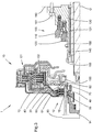
- the torque transmission module 1 is in an assembled state and comprises in particular a wet clutch mechanism 10 of axis of rotation O fixed on an actuation system 100.
- the wet clutch mechanism 10 is a wet double clutch mechanism comprising a first clutch E1 and a second clutch E2.
- the wet clutch mechanism 10 comprises around the axis O at least one input element 12 which is linked in rotation to a driving shaft (not shown).
- the input element 12 is located at the rear of the double clutch mechanism.
- the input element 12 generally having an “L” shape, comprises an annular portion of radial orientation formed by an entry veil 13 and a portion of axial orientation formed by a hub 14.
- the entry web 13 and the inlet hub 14 are integral and welded together by laser welding by transparency.
- the hub 14 is arranged radially inside with respect to the inlet web 13.
- the input hub 14 is for example linked in rotation by means of grooves to the output of a damping device (such as a double damping flywheel, etc.) whose input is linked, by the particularly through an engine flywheel, the driving shaft formed by a crankshaft which rotates an engine fitted to the motor vehicle.
- a damping device such as a double damping flywheel, etc.
- the entry veil 13 has, at its external radial end of axial orientation, teeth 19 which extend radially outwards and which are supported on an entry disc holder 20.
- the veil 13 of input and the input torque carrier 20 are rotational and have a common function of transmitting the input torque.
- the entry veil 13 is in this case attached to the entry disc holder 20.
- the entry veil can be welded to the entry disc holder 20.
- the entry veil can be directly integrated into the entry disc holder 20 so that it forms a single piece. In this way, the input disc holder 20 is arranged to be linked in rotation with the driving shaft according to an axis of rotation O.
- the wet clutch mechanism 10 is controlled to selectively couple said shaft leading to a first driven shaft A1 and to a second driven shaft A2 connected to a gearbox fitted to the motor vehicle.
- first driven shaft A1 and the second driven shaft A2 are coaxial.
- the first driven shaft A1 is driven in rotation when said first clutch E1 is closed and the second driven shaft A2 is driven in rotation when said second clutch E2 is closed.
- the torque transmission module 1 also includes an actuation system 100 arranged to engage or disengage said first and second clutches E1, E2.
- the actuation system 100 comprises an axial extension range 140 integrated in the casing and extending axially in the direction of the input element 12.
- the axial extension range 140 of the actuation system 100 is coupled in rotation with the housing 130.
- the axial extension range 140 is made in one piece with the housing 130.
- the axial extension range 140 comprises a free end oriented in the direction of the input hub 14.
- a guide bearing 150 is arranged radially between the axial extension bearing 140 acting as a clutch support and the input disc holder 20.
- the guide bearing 150 which can be a ball bearing or a needle bearing , guides the first and second clutches E1, E2 in rotation relative to the actuation system 100.
- the guide bearing 150 is in axial support on the input disc holder 20.
- the guide bearing 150 is inserted in a portion cylindrical support 23 of the input disc holder 20 so as to be able to withstand the radial forces of the wet clutch mechanism.
- the guide bearing 150 also takes up the axial forces.
- said guide bearing 150 is an angular contact ball bearing and comprises bearing elements 151 arranged radially between an outer guide ring 152 and an inner guide ring 153.
- a lubrication ring 60 is also disposed radially between the axial extension surface 140 and the input disc holder 20.
- the lubrication ring is in axial support on the guide bearing 150.
- the lubrication ring notably comprises a portion threaded 62 adapted to be screwed onto the torque transmission module.
- the wet clutch mechanism and the actuation system are fixed integrally by means of a threaded connection 62, 155 in which the lubrication ring 60 is screwed directly on the axial extension bearing 140.
- the threaded connection 62, 155 is arranged on the free end of the axial extending bearing 140.
- the axial extension range 140 of the actuation system 100 comprises a threaded portion 155 complementary to the threaded portion 62 of the lubrication ring 60.
- the guide bearing 150 is in axial support on a stop element 156.
- the stop element 156 is a split ring, inserted in an annular groove formed in the axial extension surface.
- the stop element can be a shoulder formed directly in the axial extension surface.
- the first clutch E1 is arranged radially beyond the second clutch E2.
- the multi-disc assembly of the first clutch E1 comprises flanges 31 linked in rotation to the input disc holder 20 and friction discs 32 linked in rotation to a first torque output disc holder 30.
- the friction discs 32 are, individually, axially interposed between two successive flanges 31.
- the output disc holder 33 of the first clutch E1 is linked in rotation by engagement with the friction discs 12 and by a splined connection with said first driven shaft A1.
- the output disc holder 33 comprises an output hub 34 connected to the driven shaft A1.
- the multi-disc assembly of the second clutch E2 comprises flanges 41 linked in rotation to the input disc holder 20 and friction discs 42 linked in rotation to a second output disc holder 43 of torque.
- the output disc holder 43 of the second clutch E2 is linked in rotation by engagement with the friction discs 42 and by a splined connection with said second driven shaft A2.
- the output disc holder 43 comprises an output hub 44 connected to the driven shaft A2.
- the input torque carrier 20 is common to the first and second clutch E1 and E2.
- the input disc holder 20 further comprises an outer disc holder 21 of the first clutch E1 and an inner disc holder 22 of the second clutch E2.
- the external disc carrier 21 of the first clutch E1 notably comprises an axial extension arranged to receive the multi-disc assembly of the first clutch.
- the axial extension forms an internal groove receiving the flanges 31 of the multidisk assembly of the first clutch E1.
- the inner disc holder 22 of the second clutch E2 comprises an axial extension arranged to receive the multi-disc assembly of the second clutch.
- the axial extension forms an internal groove receiving the flanges 41 of the multidisk assembly of the second clutch E2.
- the input disc holder 20 On its internal periphery, the input disc holder 20 comprises the cylindrical support portion 23 into which the guide bearing 150 is inserted.
- the wet clutch mechanism 10 comprises the lubrication ring 60 of the clutch axially interposed between the inner guide ring 153 of the guide bearing and the outlet hub 34 of the first outlet disc holder 33.
- the lubrication ring 60 is of annular shape.
- the inner bore of the lubrication ring is threaded.
- the lubrication ring comprises lubrication lines 61 passing radially right through the ring and opening onto the outer periphery.
- the casing 130 of the actuation system 100 comprises cooling fluid supply lines 131 which communicate directly with the lubrication lines 61 of the lubrication ring.
- the lubrication ring 60 thus channels the cooling fluid coming from the actuation system towards the first and second clutches E1, E2 and promotes their lubrication.
- the lubrication ring 60 also includes a cylindrical centering surface 64 intended to center an axial bearing 25.
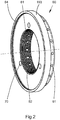
- the wet clutch mechanism 10 also comprises gripping means 70 formed on the lubrication ring 60. These gripping means are capable of receiving a gripping tool used during the assembly of the wet clutch mechanism on the module torque transmission.
- the gripping means 70 formed on the lubrication ring 60 comprise blind holes 70 distributed angularly around the axis O.
- the blind holes 70 are oriented axially parallel to the axis O.
- the gripping means 70 are formed on a lateral face of the lubrication ring 60 oriented axially in the direction of the input element 12.
- the lubrication ring 60 comprises a threaded portion 62 formed on the inner bore of the ring.
- the lubrication lines 61 are angularly distributed around the axis O.
- the lubrication lines 61 open into the inner bore and the outer periphery of the lubrication ring 60.
- the blind holes 70 do not communicate with the lubrication lines 61. The cooling efficiency of the wet clutch mechanism 10 is thus improved .
- the torque transmission module 1 is in a disassembled state.
- the wet clutch mechanism 10 is detached from the actuation system 100.
- the actuation system 100 is shown fixed to a transmission casing 160 by means of fixing screws 161.
- the assembly requires the use of a gripping tool 80 which is supplied with the torque transmission module 1 so as to form an assembly kit.
- the gripping tool 80 is able to penetrate into the gripping means 70 produced in the form of blind holes or grooves.
- Tool passage openings 15, 35, 45 are arranged on the input disc holder 20 and on the first and second outlet disc holders 33, 43.
- the tool passage openings are oriented axially in the direction gripping means 70 and allow the tool to pass through the clutches E1 and E2 when the wet clutch mechanism is placed in a first indexing position. In this first angular indexing position of the input and output disc holders, the tool passage openings are substantially coaxial with the blind holes 70 of the lubrication ring 60.
- the succession of tool passage openings 15, 35, 45 forms a set of tool passage openings.
- the wet clutch mechanism can comprise several sets of tool passage openings distributed angularly around the axis O.
- the set of tool passage openings 15, 35, 45 delimits a rectilinear passage channel along an axis of penetration parallel to the axis of rotation O which passes through the wet clutch mechanism right through up to the gripping means 70 formed on the lubrication ring 60.
- the set of tool passage openings comprises a first opening 15 formed in the inlet web 13, a second opening 35 formed in the outlet hub 34 of the first outlet disc holder 33 and a third opening 45 formed in the outlet hub 44 of the second outlet disc holder 43.
- the torque transmission module is completely assembled.
- the screwing takes place until the wet clutch mechanism 10 abuts on the housing 130 of the actuating system, that is to say until the guide bearing 150 comes into abutment on the stop element 156.
- the screwing of the pre-assembled sub-assembly, constituted by the wet clutch mechanism 10, on the casing of the actuation system creates a connection without play between the two sub-assemblies.
- the threaded connection makes it possible to recover all of the assembly and manufacturing tolerances present in the wet clutch mechanism 10.
- the figure 4 presents a second embodiment of the invention similar to the first embodiment in which the lubrication ring 60 comprises a threaded portion 62 formed on an external bearing of said ring.
- the threaded portion 62 is external.
- the threaded portion 62 is screwed onto a complementary threaded portion 155 formed on the inner bore of the free end of the axial extension surface 140.
- the actuation system 100 comprises an axial extension range 140 attached to the casing 130 of the actuation system 100.
- the axial extension range 140 is force-fitted into the casing 130 of the actuation system 100.
- the torque transmission module illustrated on the figure 4 is functionally identical to that illustrated on the Figures 1 to 3 .
- the invention is not limited to the exemplary embodiments which have just been described.
- the wet clutch mechanism according to the invention may also be suitable for the cut-off clutch mechanism, of type K0, used in hybrid transmissions for couple the internal combustion engine to the electric motor after the vehicle has started up.
- the wet clutch mechanism includes only one clutch.
Landscapes
- Engineering & Computer Science (AREA)
- General Engineering & Computer Science (AREA)
- Mechanical Engineering (AREA)
- Mechanical Operated Clutches (AREA)
- Hydraulic Clutches, Magnetic Clutches, Fluid Clutches, And Fluid Joints (AREA)
Applications Claiming Priority (1)
| Application Number | Priority Date | Filing Date | Title |
|---|---|---|---|
| FR1857163A FR3084707B1 (fr) | 2018-07-31 | 2018-07-31 | Mecanisme d'embrayage humide et module de transmission de couple comprenant ce mecanisme d'embrayage humide |
Publications (3)
| Publication Number | Publication Date |
|---|---|
| EP3604846A2 true EP3604846A2 (de) | 2020-02-05 |
| EP3604846A3 EP3604846A3 (de) | 2020-03-04 |
| EP3604846B1 EP3604846B1 (de) | 2022-08-31 |
Family
ID=65200966
Family Applications (1)
| Application Number | Title | Priority Date | Filing Date |
|---|---|---|---|
| EP19182068.7A Active EP3604846B1 (de) | 2018-07-31 | 2019-06-24 | Nasskupplungsmechanismus und drehmomentübertragungsmodul, das einen solchen nasskupplungsmechanismus umfasst |
Country Status (4)
| Country | Link |
|---|---|
| EP (1) | EP3604846B1 (de) |
| KR (1) | KR20200014226A (de) |
| CN (1) | CN110778617B (de) |
| FR (1) | FR3084707B1 (de) |
Families Citing this family (3)
| Publication number | Priority date | Publication date | Assignee | Title |
|---|---|---|---|---|
| CN116249843B (zh) * | 2020-10-28 | 2026-03-20 | 舍弗勒技术股份两合公司 | 离合器和混合动力系统 |
| CN117136282A (zh) * | 2021-03-29 | 2023-11-28 | 麦格纳Pt有限两合公司 | 具有连接的补偿室的多重片式离合器装置、尤其三重片式离合器 |
| CN117120738A (zh) * | 2021-03-29 | 2023-11-24 | 麦格纳Pt有限两合公司 | 具有支撑盘的多重片式离合器装置、尤其三重片式离合器 |
Citations (2)
| Publication number | Priority date | Publication date | Assignee | Title |
|---|---|---|---|---|
| US20140182994A1 (en) | 2011-07-11 | 2014-07-03 | Schaeffler Technologies Gmbh & Co. Kg | Release device |
| WO2018002930A1 (en) | 2016-06-30 | 2018-01-04 | Stem Cell Medicine Ltd. | Treatment of inflammatory bowel disease with long acting glatiramer and adipose-derived stem cells |
Family Cites Families (10)
| Publication number | Priority date | Publication date | Assignee | Title |
|---|---|---|---|---|
| EP1515059B1 (de) * | 2003-09-09 | 2008-03-19 | BorgWarner Inc. | Einrichtung zur axialen Sicherung einer Kupplungseinrichtung an einer Drehdurchführung |
| DE102004012948B4 (de) * | 2004-03-17 | 2012-05-31 | Zf Friedrichshafen Ag | Doppelkupplungseinrichtung in axialer Bauart |
| DE102007024788A1 (de) * | 2007-02-08 | 2008-08-14 | Borgwarner Inc., Auburn Hills | Kupplungseinrichtung mit Befestigungsmittel zur Fixierung der Ausgangsnabe |
| DE102010010922C5 (de) * | 2009-08-14 | 2024-08-08 | Borgwarner Inc. | Parallele Doppelkupplungseinrichtung und Antriebsstrang mit einer solchen parallelen Doppelkupplungseinrichtung |
| CN102200173A (zh) * | 2010-03-25 | 2011-09-28 | 博格华纳公司 | 同心双离合器装置 |
| DE102012006730B4 (de) * | 2012-04-02 | 2024-07-18 | Borgwarner Inc. | Kupplungseinrichtung |
| FR3049023B1 (fr) * | 2016-03-16 | 2019-04-26 | Valeo Embrayages | Double embrayage humide supporte sur son systeme de commande |
| FR3049025B1 (fr) * | 2016-03-16 | 2019-04-26 | Valeo Embrayages | Mecanisme d'embrayage et procede d'assemblage d'un tel mecanisme sur une chaine de transmission |
| FR3049022B1 (fr) * | 2016-03-16 | 2019-04-26 | Valeo Embrayages | Double embrayage humide a organes de transmission de force centres |
| FR3051861B1 (fr) * | 2016-05-31 | 2019-07-26 | Valeo Embrayages | Systeme de refroidissement pour mecanisme d’embrayage |
-
2018
- 2018-07-31 FR FR1857163A patent/FR3084707B1/fr not_active Expired - Fee Related
-
2019
- 2019-06-24 EP EP19182068.7A patent/EP3604846B1/de active Active
- 2019-07-29 KR KR1020190091927A patent/KR20200014226A/ko not_active Ceased
- 2019-07-29 CN CN201910688354.2A patent/CN110778617B/zh active Active
Patent Citations (2)
| Publication number | Priority date | Publication date | Assignee | Title |
|---|---|---|---|---|
| US20140182994A1 (en) | 2011-07-11 | 2014-07-03 | Schaeffler Technologies Gmbh & Co. Kg | Release device |
| WO2018002930A1 (en) | 2016-06-30 | 2018-01-04 | Stem Cell Medicine Ltd. | Treatment of inflammatory bowel disease with long acting glatiramer and adipose-derived stem cells |
Also Published As
| Publication number | Publication date |
|---|---|
| KR20200014226A (ko) | 2020-02-10 |
| FR3084707A1 (fr) | 2020-02-07 |
| EP3604846A3 (de) | 2020-03-04 |
| CN110778617B (zh) | 2023-11-28 |
| FR3084707B1 (fr) | 2021-11-26 |
| EP3604846B1 (de) | 2022-08-31 |
| CN110778617A (zh) | 2020-02-11 |
Similar Documents
| Publication | Publication Date | Title |
|---|---|---|
| EP2990678B1 (de) | Kupplungsvorrichtung für kraftfahrzeug | |
| EP3604846B1 (de) | Nasskupplungsmechanismus und drehmomentübertragungsmodul, das einen solchen nasskupplungsmechanismus umfasst | |
| EP3879133B1 (de) | Doppelnasskupplung | |
| EP3580468B1 (de) | Lösbarer doppelkupplungsmechanismus | |
| FR3084708A1 (fr) | Mecanisme d'embrayage humide et module de transmission de couple comprenant ce mecanisme d'embrayage humide | |
| FR3081952A1 (fr) | Porte-disque assemble et mecanisme d'embrayage humide comprenant ce porte-disque assemble | |
| FR3059065A1 (fr) | Assemblage radial d'un mecanisme d'embrayage sur une transmission | |
| FR3081948A1 (fr) | Systeme de transmission de couple et transmission comprenant un tel systeme de transmission de couple | |
| EP3825568A1 (de) | Vorrichtung zur drehmomentübertragung | |
| FR3078378A1 (fr) | Dispositif de transmission pour vehicule | |
| EP4180681B1 (de) | Verbesserte nasskupplung für ein motorisiertes antriebssystem | |
| EP1801441A1 (de) | Einscheibentrockenkupplung für Fahrzeuggetriebe mit Verstärkungvorrichtung für das Einkuppeln | |
| FR3122232A1 (fr) | Porte-disque assemblé et embrayage humide comprenant ce porte-disque assemblé | |
| FR3097603A1 (fr) | Mecanisme a double embrayage humide et module de transmission de couple comprenant un tel mecanisme | |
| FR3092373A1 (fr) | Double embrayage humide et dispositif de rappel elastique pour un tel double embrayage humide | |
| EP3857090B1 (de) | Kompakter doppelnasskupplungsmechanismus | |
| FR3078376A1 (fr) | Dispositif de transmission pour vehicule hybride | |
| FR3078377A1 (fr) | Dispositif de transmission pour vehicule hybride | |
| EP1445513A1 (de) | Getriebegehäuse | |
| WO2020216870A1 (fr) | Systeme de transmission de couple pour un vehicule hybride ou electrique | |
| FR3097921A1 (fr) | Dispositif de transmission pour véhicule hybride | |
| EP3810947A1 (de) | Schmierungsring und kupplungsmodul mit einem solchen schmierungsring | |
| FR3117063A1 (fr) | Dispositif de transmission de couple, en particulier pour véhicule automobile | |
| FR3115081A1 (fr) | « dispositif de rappel elastique pour systeme d’embrayage » | |
| FR3077857A1 (fr) | Dispositif de transmission pour vehicule hybride |
Legal Events
| Date | Code | Title | Description |
|---|---|---|---|
| PUAI | Public reference made under article 153(3) epc to a published international application that has entered the european phase |
Free format text: ORIGINAL CODE: 0009012 |
|
| STAA | Information on the status of an ep patent application or granted ep patent |
Free format text: STATUS: REQUEST FOR EXAMINATION WAS MADE |
|
| PUAL | Search report despatched |
Free format text: ORIGINAL CODE: 0009013 |
|
| 17P | Request for examination filed |
Effective date: 20190624 |
|
| AK | Designated contracting states |
Kind code of ref document: A2 Designated state(s): AL AT BE BG CH CY CZ DE DK EE ES FI FR GB GR HR HU IE IS IT LI LT LU LV MC MK MT NL NO PL PT RO RS SE SI SK SM TR |
|
| AX | Request for extension of the european patent |
Extension state: BA ME |
|
| STAA | Information on the status of an ep patent application or granted ep patent |
Free format text: STATUS: EXAMINATION IS IN PROGRESS |
|
| AK | Designated contracting states |
Kind code of ref document: A3 Designated state(s): AL AT BE BG CH CY CZ DE DK EE ES FI FR GB GR HR HU IE IS IT LI LT LU LV MC MK MT NL NO PL PT RO RS SE SI SK SM TR |
|
| AX | Request for extension of the european patent |
Extension state: BA ME |
|
| RIC1 | Information provided on ipc code assigned before grant |
Ipc: F16D 25/12 20060101ALI20200127BHEP Ipc: F16D 25/10 20060101AFI20200127BHEP Ipc: F16D 21/06 20060101ALI20200127BHEP |
|
| 17Q | First examination report despatched |
Effective date: 20200218 |
|
| GRAP | Despatch of communication of intention to grant a patent |
Free format text: ORIGINAL CODE: EPIDOSNIGR1 |
|
| STAA | Information on the status of an ep patent application or granted ep patent |
Free format text: STATUS: GRANT OF PATENT IS INTENDED |
|
| INTG | Intention to grant announced |
Effective date: 20220422 |
|
| GRAS | Grant fee paid |
Free format text: ORIGINAL CODE: EPIDOSNIGR3 |
|
| GRAA | (expected) grant |
Free format text: ORIGINAL CODE: 0009210 |
|
| STAA | Information on the status of an ep patent application or granted ep patent |
Free format text: STATUS: THE PATENT HAS BEEN GRANTED |
|
| AK | Designated contracting states |
Kind code of ref document: B1 Designated state(s): AL AT BE BG CH CY CZ DE DK EE ES FI FR GB GR HR HU IE IS IT LI LT LU LV MC MK MT NL NO PL PT RO RS SE SI SK SM TR |
|
| REG | Reference to a national code |
Ref country code: CH Ref legal event code: EP Ref country code: GB Ref legal event code: FG4D Free format text: NOT ENGLISH |
|
| REG | Reference to a national code |
Ref country code: AT Ref legal event code: REF Ref document number: 1515493 Country of ref document: AT Kind code of ref document: T Effective date: 20220915 |
|
| REG | Reference to a national code |
Ref country code: DE Ref legal event code: R096 Ref document number: 602019018853 Country of ref document: DE |
|
| REG | Reference to a national code |
Ref country code: IE Ref legal event code: FG4D Free format text: LANGUAGE OF EP DOCUMENT: FRENCH |
|
| REG | Reference to a national code |
Ref country code: LT Ref legal event code: MG9D |
|
| REG | Reference to a national code |
Ref country code: NL Ref legal event code: MP Effective date: 20220831 |
|
| PG25 | Lapsed in a contracting state [announced via postgrant information from national office to epo] |
Ref country code: SE Free format text: LAPSE BECAUSE OF FAILURE TO SUBMIT A TRANSLATION OF THE DESCRIPTION OR TO PAY THE FEE WITHIN THE PRESCRIBED TIME-LIMIT Effective date: 20220831 Ref country code: RS Free format text: LAPSE BECAUSE OF FAILURE TO SUBMIT A TRANSLATION OF THE DESCRIPTION OR TO PAY THE FEE WITHIN THE PRESCRIBED TIME-LIMIT Effective date: 20220831 Ref country code: NO Free format text: LAPSE BECAUSE OF FAILURE TO SUBMIT A TRANSLATION OF THE DESCRIPTION OR TO PAY THE FEE WITHIN THE PRESCRIBED TIME-LIMIT Effective date: 20221130 Ref country code: LV Free format text: LAPSE BECAUSE OF FAILURE TO SUBMIT A TRANSLATION OF THE DESCRIPTION OR TO PAY THE FEE WITHIN THE PRESCRIBED TIME-LIMIT Effective date: 20220831 Ref country code: LT Free format text: LAPSE BECAUSE OF FAILURE TO SUBMIT A TRANSLATION OF THE DESCRIPTION OR TO PAY THE FEE WITHIN THE PRESCRIBED TIME-LIMIT Effective date: 20220831 Ref country code: FI Free format text: LAPSE BECAUSE OF FAILURE TO SUBMIT A TRANSLATION OF THE DESCRIPTION OR TO PAY THE FEE WITHIN THE PRESCRIBED TIME-LIMIT Effective date: 20220831 |
|
| REG | Reference to a national code |
Ref country code: AT Ref legal event code: MK05 Ref document number: 1515493 Country of ref document: AT Kind code of ref document: T Effective date: 20220831 |
|
| PG25 | Lapsed in a contracting state [announced via postgrant information from national office to epo] |
Ref country code: PL Free format text: LAPSE BECAUSE OF FAILURE TO SUBMIT A TRANSLATION OF THE DESCRIPTION OR TO PAY THE FEE WITHIN THE PRESCRIBED TIME-LIMIT Effective date: 20220831 Ref country code: IS Free format text: LAPSE BECAUSE OF FAILURE TO SUBMIT A TRANSLATION OF THE DESCRIPTION OR TO PAY THE FEE WITHIN THE PRESCRIBED TIME-LIMIT Effective date: 20221231 Ref country code: HR Free format text: LAPSE BECAUSE OF FAILURE TO SUBMIT A TRANSLATION OF THE DESCRIPTION OR TO PAY THE FEE WITHIN THE PRESCRIBED TIME-LIMIT Effective date: 20220831 Ref country code: GR Free format text: LAPSE BECAUSE OF FAILURE TO SUBMIT A TRANSLATION OF THE DESCRIPTION OR TO PAY THE FEE WITHIN THE PRESCRIBED TIME-LIMIT Effective date: 20221201 |
|
| PG25 | Lapsed in a contracting state [announced via postgrant information from national office to epo] |
Ref country code: SM Free format text: LAPSE BECAUSE OF FAILURE TO SUBMIT A TRANSLATION OF THE DESCRIPTION OR TO PAY THE FEE WITHIN THE PRESCRIBED TIME-LIMIT Effective date: 20220831 Ref country code: RO Free format text: LAPSE BECAUSE OF FAILURE TO SUBMIT A TRANSLATION OF THE DESCRIPTION OR TO PAY THE FEE WITHIN THE PRESCRIBED TIME-LIMIT Effective date: 20220831 Ref country code: PT Free format text: LAPSE BECAUSE OF FAILURE TO SUBMIT A TRANSLATION OF THE DESCRIPTION OR TO PAY THE FEE WITHIN THE PRESCRIBED TIME-LIMIT Effective date: 20230102 Ref country code: ES Free format text: LAPSE BECAUSE OF FAILURE TO SUBMIT A TRANSLATION OF THE DESCRIPTION OR TO PAY THE FEE WITHIN THE PRESCRIBED TIME-LIMIT Effective date: 20220831 Ref country code: DK Free format text: LAPSE BECAUSE OF FAILURE TO SUBMIT A TRANSLATION OF THE DESCRIPTION OR TO PAY THE FEE WITHIN THE PRESCRIBED TIME-LIMIT Effective date: 20220831 Ref country code: CZ Free format text: LAPSE BECAUSE OF FAILURE TO SUBMIT A TRANSLATION OF THE DESCRIPTION OR TO PAY THE FEE WITHIN THE PRESCRIBED TIME-LIMIT Effective date: 20220831 Ref country code: AT Free format text: LAPSE BECAUSE OF FAILURE TO SUBMIT A TRANSLATION OF THE DESCRIPTION OR TO PAY THE FEE WITHIN THE PRESCRIBED TIME-LIMIT Effective date: 20220831 |
|
| PG25 | Lapsed in a contracting state [announced via postgrant information from national office to epo] |
Ref country code: SK Free format text: LAPSE BECAUSE OF FAILURE TO SUBMIT A TRANSLATION OF THE DESCRIPTION OR TO PAY THE FEE WITHIN THE PRESCRIBED TIME-LIMIT Effective date: 20220831 Ref country code: EE Free format text: LAPSE BECAUSE OF FAILURE TO SUBMIT A TRANSLATION OF THE DESCRIPTION OR TO PAY THE FEE WITHIN THE PRESCRIBED TIME-LIMIT Effective date: 20220831 |
|
| REG | Reference to a national code |
Ref country code: DE Ref legal event code: R097 Ref document number: 602019018853 Country of ref document: DE |
|
| PG25 | Lapsed in a contracting state [announced via postgrant information from national office to epo] |
Ref country code: NL Free format text: LAPSE BECAUSE OF FAILURE TO SUBMIT A TRANSLATION OF THE DESCRIPTION OR TO PAY THE FEE WITHIN THE PRESCRIBED TIME-LIMIT Effective date: 20220831 Ref country code: AL Free format text: LAPSE BECAUSE OF FAILURE TO SUBMIT A TRANSLATION OF THE DESCRIPTION OR TO PAY THE FEE WITHIN THE PRESCRIBED TIME-LIMIT Effective date: 20220831 |
|
| PLBE | No opposition filed within time limit |
Free format text: ORIGINAL CODE: 0009261 |
|
| STAA | Information on the status of an ep patent application or granted ep patent |
Free format text: STATUS: NO OPPOSITION FILED WITHIN TIME LIMIT |
|
| P01 | Opt-out of the competence of the unified patent court (upc) registered |
Effective date: 20230528 |
|
| 26N | No opposition filed |
Effective date: 20230601 |
|
| PG25 | Lapsed in a contracting state [announced via postgrant information from national office to epo] |
Ref country code: SI Free format text: LAPSE BECAUSE OF FAILURE TO SUBMIT A TRANSLATION OF THE DESCRIPTION OR TO PAY THE FEE WITHIN THE PRESCRIBED TIME-LIMIT Effective date: 20220831 |
|
| PG25 | Lapsed in a contracting state [announced via postgrant information from national office to epo] |
Ref country code: MC Free format text: LAPSE BECAUSE OF FAILURE TO SUBMIT A TRANSLATION OF THE DESCRIPTION OR TO PAY THE FEE WITHIN THE PRESCRIBED TIME-LIMIT Effective date: 20220831 |
|
| PG25 | Lapsed in a contracting state [announced via postgrant information from national office to epo] |
Ref country code: MC Free format text: LAPSE BECAUSE OF FAILURE TO SUBMIT A TRANSLATION OF THE DESCRIPTION OR TO PAY THE FEE WITHIN THE PRESCRIBED TIME-LIMIT Effective date: 20220831 |
|
| REG | Reference to a national code |
Ref country code: CH Ref legal event code: PL |
|
| REG | Reference to a national code |
Ref country code: BE Ref legal event code: MM Effective date: 20230630 |
|
| GBPC | Gb: european patent ceased through non-payment of renewal fee |
Effective date: 20230624 |
|
| PG25 | Lapsed in a contracting state [announced via postgrant information from national office to epo] |
Ref country code: LU Free format text: LAPSE BECAUSE OF NON-PAYMENT OF DUE FEES Effective date: 20230624 |
|
| REG | Reference to a national code |
Ref country code: IE Ref legal event code: MM4A |
|
| PG25 | Lapsed in a contracting state [announced via postgrant information from national office to epo] |
Ref country code: LU Free format text: LAPSE BECAUSE OF NON-PAYMENT OF DUE FEES Effective date: 20230624 |
|
| PG25 | Lapsed in a contracting state [announced via postgrant information from national office to epo] |
Ref country code: IE Free format text: LAPSE BECAUSE OF NON-PAYMENT OF DUE FEES Effective date: 20230624 |
|
| PG25 | Lapsed in a contracting state [announced via postgrant information from national office to epo] |
Ref country code: IE Free format text: LAPSE BECAUSE OF NON-PAYMENT OF DUE FEES Effective date: 20230624 Ref country code: GB Free format text: LAPSE BECAUSE OF NON-PAYMENT OF DUE FEES Effective date: 20230624 Ref country code: CH Free format text: LAPSE BECAUSE OF NON-PAYMENT OF DUE FEES Effective date: 20230630 |
|
| PG25 | Lapsed in a contracting state [announced via postgrant information from national office to epo] |
Ref country code: IT Free format text: LAPSE BECAUSE OF FAILURE TO SUBMIT A TRANSLATION OF THE DESCRIPTION OR TO PAY THE FEE WITHIN THE PRESCRIBED TIME-LIMIT Effective date: 20220831 Ref country code: BE Free format text: LAPSE BECAUSE OF NON-PAYMENT OF DUE FEES Effective date: 20230630 |
|
| PG25 | Lapsed in a contracting state [announced via postgrant information from national office to epo] |
Ref country code: BG Free format text: LAPSE BECAUSE OF FAILURE TO SUBMIT A TRANSLATION OF THE DESCRIPTION OR TO PAY THE FEE WITHIN THE PRESCRIBED TIME-LIMIT Effective date: 20220831 |
|
| PG25 | Lapsed in a contracting state [announced via postgrant information from national office to epo] |
Ref country code: BG Free format text: LAPSE BECAUSE OF FAILURE TO SUBMIT A TRANSLATION OF THE DESCRIPTION OR TO PAY THE FEE WITHIN THE PRESCRIBED TIME-LIMIT Effective date: 20220831 |
|
| PGFP | Annual fee paid to national office [announced via postgrant information from national office to epo] |
Ref country code: DE Payment date: 20250617 Year of fee payment: 7 |
|
| PGFP | Annual fee paid to national office [announced via postgrant information from national office to epo] |
Ref country code: FR Payment date: 20250630 Year of fee payment: 7 |
|
| PG25 | Lapsed in a contracting state [announced via postgrant information from national office to epo] |
Ref country code: CY Free format text: LAPSE BECAUSE OF FAILURE TO SUBMIT A TRANSLATION OF THE DESCRIPTION OR TO PAY THE FEE WITHIN THE PRESCRIBED TIME-LIMIT; INVALID AB INITIO Effective date: 20190624 |
|
| PG25 | Lapsed in a contracting state [announced via postgrant information from national office to epo] |
Ref country code: HU Free format text: LAPSE BECAUSE OF FAILURE TO SUBMIT A TRANSLATION OF THE DESCRIPTION OR TO PAY THE FEE WITHIN THE PRESCRIBED TIME-LIMIT; INVALID AB INITIO Effective date: 20190624 |
|
| PG25 | Lapsed in a contracting state [announced via postgrant information from national office to epo] |
Ref country code: TR Free format text: LAPSE BECAUSE OF FAILURE TO SUBMIT A TRANSLATION OF THE DESCRIPTION OR TO PAY THE FEE WITHIN THE PRESCRIBED TIME-LIMIT Effective date: 20220831 |