EP3604814A1 - Screw type fluid machine - Google Patents
Screw type fluid machine Download PDFInfo
- Publication number
- EP3604814A1 EP3604814A1 EP17861211.5A EP17861211A EP3604814A1 EP 3604814 A1 EP3604814 A1 EP 3604814A1 EP 17861211 A EP17861211 A EP 17861211A EP 3604814 A1 EP3604814 A1 EP 3604814A1
- Authority
- EP
- European Patent Office
- Prior art keywords
- female
- male
- oil
- rotor
- penetration hole
- Prior art date
- Legal status (The legal status is an assumption and is not a legal conclusion. Google has not performed a legal analysis and makes no representation as to the accuracy of the status listed.)
- Withdrawn
Links
- 239000012530 fluid Substances 0.000 title claims abstract description 52
- 230000035515 penetration Effects 0.000 claims abstract description 56
- 238000004891 communication Methods 0.000 claims description 10
- 238000010438 heat treatment Methods 0.000 abstract description 9
- 239000007789 gas Substances 0.000 description 23
- 230000007423 decrease Effects 0.000 description 4
- 238000005553 drilling Methods 0.000 description 4
- 239000002826 coolant Substances 0.000 description 2
- 238000000034 method Methods 0.000 description 2
- CURLTUGMZLYLDI-UHFFFAOYSA-N Carbon dioxide Chemical class O=C=O CURLTUGMZLYLDI-UHFFFAOYSA-N 0.000 description 1
- 238000007792 addition Methods 0.000 description 1
- 238000004378 air conditioning Methods 0.000 description 1
- 229910002092 carbon dioxide Inorganic materials 0.000 description 1
- 230000006835 compression Effects 0.000 description 1
- 238000007906 compression Methods 0.000 description 1
- 238000012986 modification Methods 0.000 description 1
- 230000004048 modification Effects 0.000 description 1
- 238000005057 refrigeration Methods 0.000 description 1
Images




Classifications
-
- F—MECHANICAL ENGINEERING; LIGHTING; HEATING; WEAPONS; BLASTING
- F04—POSITIVE - DISPLACEMENT MACHINES FOR LIQUIDS; PUMPS FOR LIQUIDS OR ELASTIC FLUIDS
- F04C—ROTARY-PISTON, OR OSCILLATING-PISTON, POSITIVE-DISPLACEMENT MACHINES FOR LIQUIDS; ROTARY-PISTON, OR OSCILLATING-PISTON, POSITIVE-DISPLACEMENT PUMPS
- F04C18/00—Rotary-piston pumps specially adapted for elastic fluids
- F04C18/08—Rotary-piston pumps specially adapted for elastic fluids of intermeshing-engagement type, i.e. with engagement of co-operating members similar to that of toothed gearing
- F04C18/12—Rotary-piston pumps specially adapted for elastic fluids of intermeshing-engagement type, i.e. with engagement of co-operating members similar to that of toothed gearing of other than internal-axis type
- F04C18/14—Rotary-piston pumps specially adapted for elastic fluids of intermeshing-engagement type, i.e. with engagement of co-operating members similar to that of toothed gearing of other than internal-axis type with toothed rotary pistons
- F04C18/16—Rotary-piston pumps specially adapted for elastic fluids of intermeshing-engagement type, i.e. with engagement of co-operating members similar to that of toothed gearing of other than internal-axis type with toothed rotary pistons with helical teeth, e.g. chevron-shaped, screw type
-
- F—MECHANICAL ENGINEERING; LIGHTING; HEATING; WEAPONS; BLASTING
- F04—POSITIVE - DISPLACEMENT MACHINES FOR LIQUIDS; PUMPS FOR LIQUIDS OR ELASTIC FLUIDS
- F04C—ROTARY-PISTON, OR OSCILLATING-PISTON, POSITIVE-DISPLACEMENT MACHINES FOR LIQUIDS; ROTARY-PISTON, OR OSCILLATING-PISTON, POSITIVE-DISPLACEMENT PUMPS
- F04C29/00—Component parts, details or accessories of pumps or pumping installations, not provided for in groups F04C18/00 - F04C28/00
- F04C29/02—Lubrication; Lubricant separation
Definitions
- the present invention relates to a screw fluid machine that handles HFC-based and HFO-based coolants, natural coolants such as air or carbon dioxides, and other compressible gases.
- a screw fluid machine has been broadly used as a refrigeration and air-conditioning compressor and an air compressor.
- the screw fluid machine is a main component of a heat pump apparatus such as an air-conditioner, a chiller, and a refrigerator.
- a heat pump apparatus such as an air-conditioner, a chiller, and a refrigerator.
- a conventional screw fluid machine is configured such that oil that has lubricated shaft support means that rotatably supports the rotor shafts of a male rotor and a female rotor flows into an inlet along the wall surfaces close to the male rotor and the female rotor, and the oil is mixed with the main stream of gas sucked from the inlet and is returned to an oil reservoir.
- an object of the present invention is to provide a screw fluid machine having high energy efficiency and high performance, capable of suppressing oil from being mixed with the main stream of gas sucked from an inlet to suppress intake gas heating.
- a screw fluid machine includes: a male rotor and a female rotor configured to rotate while engaging with each other; shaft support means for rotatably supporting driving shafts of the male rotor and the female rotor; driving means for driving the male rotor and the female rotor; a casing configured to accommodate the male rotor, the female rotor, the shaft support means, and the driving means; and oil supply means for supplying oil to the shaft support means, wherein the casing has an intermediate portion positioned between the driving means, and the male rotor and the female rotor, the intermediate portion includes, formed therein, a male penetration hole through which the driving shaft of the male rotor passes, a female penetration hole through which the driving shaft of the female rotor passes, an inlet opening for sucking gas from the driving means toward the male rotor and the female rotor, and an oil exhaust passage portion communicating with the male penetration hole and the female penetration hole so as to return the oil that has lubric
- this screw fluid machine having high energy efficiency and high performance, this screw fluid machine being capable of suppressing oil from being mixed with the main stream of gas sucked from an inlet to suppress intake gas heating.
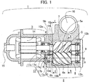
- Fig. 1 illustrates a horizontal cross-sectional view of the screw fluid machine 1 according to the present embodiment
- Fig. 2 illustrates a cross-sectional view along line A-A in Fig. 1 , of the screw fluid machine 1 of the first embodiment
- Fig. 3 illustrates a cross-sectional view along line B-B in Fig. 1 , of the screw fluid machine 1 according to the first embodiment
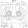
- Fig. 4 illustrates a cross-sectional view along line C-C in Fig. 1 , of the screw fluid machine 1 according to the first embodiment.
- the screw fluid machine 1 includes a compressing portion 2, a driving portion 3, and a casing 4 that accommodates the compressing portion 2 and the driving portion 3.
- the screw fluid machine 1 causes gas sucked from an inlet port 15 formed in the casing 4 into the screw fluid machine 1 to pass through a motor 14 and then causes the gas to be sucked into an operating chamber from an inlet opening 10 of the operating chamber formed in an intermediate portion 4A.
- the screw fluid machine 1 compresses the sucked gas and exhausts the gas outside the screw fluid machine 1 from an exhaust port 16 through an exhaust opening 11 of the operating chamber.
- the compressing portion 2 includes a male rotor 5 that is rotated by the motor 14 which is driving means arranged in the driving portion 3, a female rotor 6 that rotates while engaging with the male rotor 5, the casing 4 that accommodates the male rotor 5 and the female rotor 6, shaft support means 12a, 12b, 13a, and 13b, oil supply means 17 of inlet-side shaft support means, and oil supply means (not illustrated) of exhaust-side shaft support means.
- the male rotor 5 and the female rotor 6 include a male rotor shaft 5b and a female rotor shaft 6b, respectively, as rotating shafts.
- the inlet-side shaft support means 12a is made up of two roller bearings that support an inlet side of the male rotor shaft 5b of the male rotor 5, and the exhaust-side shaft support means 12b is made up of a roller bearing and a ball bearing that support an exhaust side of the male rotor shaft 5b of the male rotor 5.
- the inlet-side shaft support means 13a is made up of a roller bearing that supports an inlet side of the female rotor shaft 6b of the female rotor 6, and the exhaust-side shaft support means 13b is made up of a roller bearing and a ball bearing that support an exhaust side of the female rotor shaft 6b of the female rotor 6.
- the casing 4 includes the intermediate portion 4A positioned between the compressing portion 2 and the driving portion 3.
- a male penetration hole 4b, a female penetration hole 4c, an inlet opening 10, and an oil exhaust passage portion 20 are formed in the intermediate portion 4A.
- the male rotor shaft 5b of the male rotor 5 also passes through the male penetration hole 4b to form a male oil passage 17d.
- the female rotor shaft 6b of the female rotor 6 passes through the female penetration hole 4c to form a female oil passage 17e.
- the inlet opening 10 has horizontal edges 10a and 10b positioned on the lower sides of the male penetration hole 4b and the female penetration hole 4c. Moreover, the inlet opening 10 is widely open to the male rotor 5 and narrowly open to the female rotor 6.
- a plurality of operating chambers are formed by tooth spaces 5a and 6a of the male rotor 5 and the female rotor 6, a bore 7 (a wall surface facing each rotor in a radial direction) of the casing 4, an inlet end surface 8 of the casing 4, and an exhaust end surface 9 of the casing 4.
- the casing 4 illustrated in Fig. 1 is illustrated as an integral structure as an example, the casing 4 may have a divided structure in which the casing 4 is divided into the compressing portion 2 and the driving portion 3 or the compressing portion 2 is divided by a casing portion in which the exhaust-side shaft support means of the male and female rotors is arranged.
- An oil supply main path 17a and an oil supply branch path 17b are formed in the casing 4 as oil supply paths to the inlet-side shaft support means 12a of the male rotor 5 and the inlet-side shaft support means 13a of the female rotor 6.
- oil is supplied using a method of supplying oil separated by an oil separator (not illustrated) by pressure difference, oil may be supplied using other methods.
- oil supplied from the oil supply main path 17a to the inlet-side shaft support means 12a does not flow toward the motor 14 with the aid of a seal member 17c that prevents oil from leaking toward the motor 14 but flows up to the male oil passage 17d formed when the male rotor shaft 5b of the male rotor 5 passes through the male penetration hole 4b of the intermediate portion 4A after the oil lubricates the inlet-side shaft support means 12a.
- oil supplied from the oil supply branch path 17b to the inlet-side shaft support means 13a flows up to a female oil passage 17e formed when the female rotor shaft 6b of the female rotor 6 passes through the female penetration hole 4c of the intermediate portion 4A after the oil lubricates the inlet-side shaft support means 13a.
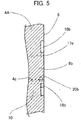
- the oil exhaust passage portion 20 for guiding oil from the male oil passage 17d and the female oil passage 17e toward an oil reservoir 21 will be described with reference to Figs. 4 and 5 .
- Fig. 5 illustrates a cross-sectional view along line D-D in Fig. 4 , of the screw fluid machine 1 according to the first embodiment.
- the inlet opening 10 of the operating chamber and a male rotor-side inlet groove 18a and a female rotor-side inlet groove 18b formed on an anti-rotor side of the inlet end surface 8 are formed in the inlet end surface 8 of the intermediate portion 4A.
- the oil exhaust passage portion 20 is also formed in the intermediate portion 4A.
- the inlet opening 10 are formed below the male rotor shaft 5a and the female rotor shaft 6b.
- the male inlet groove 18a and the female inlet groove 18b are formed so as to extend along portions of the outer circumferences of the male rotor shaft 5a and the female rotor shaft 6b, respectively.
- a boundary 19a between the inlet opening 10 and the male inlet groove 18a is positioned on a right side of a lower portion of the female rotor shaft 6b in Fig. 4
- a boundary 19b between the inlet opening 10 and the female inlet groove 18b is positioned immediately below the female rotor shaft 6b.
- the boundaries 19a and 19b correspond to the edges 10a and 10b in the horizontal direction of the inlet opening 10, respectively.
- the oil exhaust passage portion 20 includes a communication passage 20a, an exhaust passage 20b, a plug 20c, and an exhaust groove 20d.
- the communication passage 20a, the exhaust passage 20b, and the exhaust groove 20d are formed by performing a single instance of drilling on the casing 4 so as to extend in a horizontal direction, and the plug 20c closes the hole in the outer surface of the casing 4.
- the communication passage 20a connects the lower portion of the male oil passage 17d and the lower portion of the female oil passage 17e.
- the exhaust passage 20b connects the female inlet groove 18b and the lower portion of the female oil passage 17e.
- the exhaust passage 20b communicates with the female penetration hole 4c and extends toward a side away from the male penetration hole 4b and is open to the female inlet groove 18b. Since the oil exhaust passage portion 20 is processed as a large-diameter hole, the exhaust groove 20d is formed by cutting the bottom surface of the female inlet groove 18b. Due to this, when the oil exhaust passage portion 20 is processed as a small-diameter hole, the exhaust groove 20d is not formed.
- the oil exhausted to the female inlet groove 18b falls along the female inlet groove 18b and flows into the oil reservoir 21 positioned close to the motor 14 from the edge 10b of the inlet opening 10.
- the oil that has lubricated the inlet-side shaft support means 12a and 13a flows in a direction (a horizontal direction in the present embodiment) crossing a vertical direction due to the oil exhaust passage portion 20 and then flows toward the motor 14 from the edge 10b of the inlet opening 10.
- the oil that has lubricated the inlet-side shaft support means 12a and 13a flows in a direction (a horizontal direction in the present embodiment) crossing the vertical direction due to the oil exhaust passage portion 20 and falls along the female inlet groove 18b so that the amount of oil present as an oil film on the female inlet groove 18b, it is possible to decrease the temperature of the oil by exchanging heat with the casing 4. As a result, it is possible to reduce heating of the gas sucked from the inlet opening 10.
- the communication passage 20a of the oil exhaust passage portion 20 communicates with the male penetration hole 4b and the female penetration hole 4c, and the exhaust passage 20b of the oil exhaust passage portion 20 communicates with the female penetration hole 4c and extends toward a side away from the male penetration hole 4b. Due to this, since the communication passage 20a and the exhaust passage 20b can be formed by performing a single instance of drilling on the casing 4, it is possible to form the communication passage 20a and the exhaust passage 20b easily.
- the motor 14 rotates the male rotor 5, and the exhaust passage 20b communicates with the female penetration hole 4c and extends toward a side away from the male penetration hole 4b. Since an opening of the casing 4 narrows with a decrease in the size of the casing 4 on the side of the inlet opening 10 where the motor 14 is not provided, when the exhaust passage 20b is configured to extend from the female penetration hole 4c toward a side away from the male penetration hole 4b, it is possible to increase the distance from an exit of the exhaust passage 20b to the inlet opening 10 and to decrease the temperature of the oil. Therefore, it is possible to suppress heating of the gas sucked from the inlet opening 10.
- a screw fluid machine 1 according to a second embodiment of the present invention will be described with reference to Fig. 6 .
- the same members as those of the screw fluid machine 1 according to the first embodiment will be denoted by the same reference numerals, and the description thereof will be omitted and different portions only will be described.
- Fig. 6 illustrates a cross-sectional view along line C-C in Fig. 1 , of the screw fluid machine 1 according to the second embodiment.
- the inlet opening 10 is positioned at the center of the male rotor shaft 5b and the female rotor shaft 6b and has a shape symmetrical to a surface parallel to the drawing sheet.
- a male oil exhaust passage portion 50 and a female oil exhaust passage portion 51 are formed in the intermediate portion 4A instead of the oil exhaust passage portion 20, and the communication passage 20a that connects the lower portion of the male oil passage 17d and the lower portion of the female oil passage 17e is not formed.
- the male oil exhaust passage portion 50 includes a male exhaust passage 50a, a plug 50b, and an exhaust groove 50c.
- the male exhaust passage 50a and the exhaust groove 50c are formed by performing drilling on the casing 4 so as to extend in a horizontal direction, and the plug 50b closes a hole in the outer surface of the casing 4.
- the male exhaust passage 50a connects the male inlet groove 18a and the lower portion of the male oil passage 17d. That is, the male exhaust passage 50a communicates with the male penetration hole 4b and extends toward a side away from the female penetration hole 4c and is open to the male inlet groove 18a. Since the male oil exhaust passage portion 50 is processed as a large-diameter hole, the exhaust groove 50c is formed by cutting the bottom surface of the male inlet groove 18a.
- the female oil exhaust passage portion 51 includes a female exhaust passage 51a, a plug 51b, and an exhaust groove 51c.
- the female exhaust passage 51a and the exhaust groove 51c are formed by performing drilling on the casing 4 so as to extend in a horizontal direction, and the plug 51b closes a hole in the outer surface of the casing 4.
- the female exhaust passage 51a connects the female inlet groove 18b and a lower portion of the female oil passage 17e. That is, the female exhaust passage 51a communicates with the female penetration hole 4c and extends toward a side away from the male penetration hole 4b and is open to the female inlet groove 18b. Since the female oil exhaust passage portion 51 is processed as a large-diameter hole, the exhaust groove 51c is formed by cutting the bottom surface of the female inlet groove 18b.
- the oil exhausted to the male inlet groove 18a falls along the male inlet groove 18a and flows from the edge 10a of the inlet opening 10 into the oil reservoir 21 positioned close to the motor 14.
- the oil that has lubricated the inlet-side shaft support means 12a flows from the edge 10a of the inlet opening 10 toward the motor 14 after flowing in a direction (a horizontal direction in the present embodiment) crossing a vertical direction due to the male oil exhaust passage portion 50.
- the oil that has lubricated the inlet-side shaft support means 13a flows from the edge 10b of the inlet opening 10 toward the motor 14 after flowing in a direction (a horizontal direction in the present embodiment) crossing in a vertical direction due to the female oil exhaust passage portion 51.
- the screw fluid machine 1 of the present embodiment since the screw fluid machine 1 has the male oil exhaust passage portion 50 close to the male rotor 5 and the female oil exhaust passage portion 51 close to the female rotor 6, it is possible to cause the oil to pass from both edges 10a and 10b of the inlet opening 10 and to suppress heat exchange between the oil and the inlet gas. Therefore, it is possible to realize the screw fluid machine 1 having high energy efficiency and high performance, capable of suppressing intake gas heating.
- Fig. 7 illustrates a cross-sectional view along line C-C in Fig. 1 , of the screw fluid machine 1 according to the third embodiment.
- an exhaust relief groove 40 that exhausts oil to a side lower than the inlet opening 10 is formed in a portion of a surface in which the female inlet groove 18b is formed and which is positioned below the female rotor shaft 6b of the female rotor 6.
- the motor 14 drives the male rotor 5
- the motor 14 may drive the female rotor 6.
- the oil exhaust passage portion 20 may be formed in the male oil passage 17d rather than the female oil passage 17e.
- the exhaust relief groove 40 may be formed in both the male inlet groove 18a and the female inlet groove 18b of the second embodiment.
Landscapes
- Engineering & Computer Science (AREA)
- Mechanical Engineering (AREA)
- General Engineering & Computer Science (AREA)
- Applications Or Details Of Rotary Compressors (AREA)
Abstract
Description
- The present invention relates to a screw fluid machine that handles HFC-based and HFO-based coolants, natural coolants such as air or carbon dioxides, and other compressible gases.
- A screw fluid machine has been broadly used as a refrigeration and air-conditioning compressor and an air compressor. The screw fluid machine is a main component of a heat pump apparatus such as an air-conditioner, a chiller, and a refrigerator. There is a strong demand for energy-saving apparatuses, and it has become more important to achieve high energy efficiency and high performance.
- A conventional screw fluid machine is configured such that oil that has lubricated shaft support means that rotatably supports the rotor shafts of a male rotor and a female rotor flows into an inlet along the wall surfaces close to the male rotor and the female rotor, and the oil is mixed with the main stream of gas sucked from the inlet and is returned to an oil reservoir.
- However, in the oil returning configuration of the conventional screw fluid machine, since the oil is mixed with the main stream of gas sucked from the inlet, heat exchange occurs between gas and oil to increase intake gas heating, and compression efficiency decreases.
- Therefore, an object of the present invention is to provide a screw fluid machine having high energy efficiency and high performance, capable of suppressing oil from being mixed with the main stream of gas sucked from an inlet to suppress intake gas heating.
- In order to solve the problem, a screw fluid machine according to an aspect of the present invention includes: a male rotor and a female rotor configured to rotate while engaging with each other; shaft support means for rotatably supporting driving shafts of the male rotor and the female rotor; driving means for driving the male rotor and the female rotor; a casing configured to accommodate the male rotor, the female rotor, the shaft support means, and the driving means; and oil supply means for supplying oil to the shaft support means, wherein the casing has an intermediate portion positioned between the driving means, and the male rotor and the female rotor, the intermediate portion includes, formed therein, a male penetration hole through which the driving shaft of the male rotor passes, a female penetration hole through which the driving shaft of the female rotor passes, an inlet opening for sucking gas from the driving means toward the male rotor and the female rotor, and an oil exhaust passage portion communicating with the male penetration hole and the female penetration hole so as to return the oil that has lubricated the shaft support means toward the driving means, and the oil that has lubricated the shaft support means is returned from the inlet opening toward the driving means through the oil exhaust passage portion so as to avoid the gas that passes through the inlet opening.
- According to the present invention, it is possible to provide a screw fluid machine having high energy efficiency and high performance, this screw fluid machine being capable of suppressing oil from being mixed with the main stream of gas sucked from an inlet to suppress intake gas heating.
-
- [
Fig. 1 ]
Fig. 1 illustrates a horizontal cross-sectional view of a screw fluid machine according to a first embodiment. - [
Fig. 2 ]
Fig. 2 illustrates a cross-sectional view along line A-A inFig. 1 , of the screw fluid machine according to the first embodiment. - [
Fig. 3 ]
Fig. 3 illustrates a cross-sectional view along line B-B inFig. 1 , of the screw fluid machine according to the first embodiment. - [
Fig. 4 ]
Fig. 4 illustrates a cross-sectional view along line C-C inFig. 1 , of the screw fluid machine according to the first embodiment. - [
Fig. 5 ]
Fig. 5 illustrates a cross-sectional view along line D-D inFig. 4 , of the screw fluid machine according to the first embodiment. - [
Fig. 6 ]
Fig. 6 illustrates a cross-sectional view along line C-C inFig. 1 , of a screw fluid machine according to a second embodiment. - [
Fig. 7 ]
Fig. 7 illustrates a cross-sectional view along line C-C inFig. 1 , of a screw fluid machine according to a third embodiment. - Hereinafter, a
screw fluid machine 1 according to a first embodiment of the present invention will be described with reference toFig. 1 . - An overall configuration of the
screw fluid machine 1 will be described with reference toFigs. 1 to 4 . -
Fig. 1 illustrates a horizontal cross-sectional view of thescrew fluid machine 1 according to the present embodiment andFig. 2 illustrates a cross-sectional view along line A-A inFig. 1 , of thescrew fluid machine 1 of the first embodiment.Fig. 3 illustrates a cross-sectional view along line B-B inFig. 1 , of thescrew fluid machine 1 according to the first embodiment.Fig. 4 illustrates a cross-sectional view along line C-C inFig. 1 , of thescrew fluid machine 1 according to the first embodiment. - As illustrated in
Fig. 1 , thescrew fluid machine 1 includes acompressing portion 2, adriving portion 3, and acasing 4 that accommodates thecompressing portion 2 and thedriving portion 3. As illustrated inFigs. 1 and2 , thescrew fluid machine 1 causes gas sucked from aninlet port 15 formed in thecasing 4 into thescrew fluid machine 1 to pass through amotor 14 and then causes the gas to be sucked into an operating chamber from an inlet opening 10 of the operating chamber formed in anintermediate portion 4A. Thescrew fluid machine 1 compresses the sucked gas and exhausts the gas outside thescrew fluid machine 1 from anexhaust port 16 through anexhaust opening 11 of the operating chamber. - The compressing
portion 2 includes amale rotor 5 that is rotated by themotor 14 which is driving means arranged in thedriving portion 3, afemale rotor 6 that rotates while engaging with themale rotor 5, thecasing 4 that accommodates themale rotor 5 and thefemale rotor 6, shaft support means 12a, 12b, 13a, and 13b, oil supply means 17 of inlet-side shaft support means, and oil supply means (not illustrated) of exhaust-side shaft support means. - The
male rotor 5 and thefemale rotor 6 include amale rotor shaft 5b and afemale rotor shaft 6b, respectively, as rotating shafts. The inlet-side shaft support means 12a is made up of two roller bearings that support an inlet side of themale rotor shaft 5b of themale rotor 5, and the exhaust-side shaft support means 12b is made up of a roller bearing and a ball bearing that support an exhaust side of themale rotor shaft 5b of themale rotor 5. The inlet-side shaft support means 13a is made up of a roller bearing that supports an inlet side of thefemale rotor shaft 6b of thefemale rotor 6, and the exhaust-side shaft support means 13b is made up of a roller bearing and a ball bearing that support an exhaust side of thefemale rotor shaft 6b of thefemale rotor 6. - The
casing 4 includes theintermediate portion 4A positioned between the compressingportion 2 and thedriving portion 3. Amale penetration hole 4b, afemale penetration hole 4c, an inlet opening 10, and an oilexhaust passage portion 20 are formed in theintermediate portion 4A. Themale rotor shaft 5b of themale rotor 5 also passes through themale penetration hole 4b to form amale oil passage 17d. Thefemale rotor shaft 6b of thefemale rotor 6 passes through thefemale penetration hole 4c to form afemale oil passage 17e. The inlet opening 10 hashorizontal edges male penetration hole 4b and thefemale penetration hole 4c. Moreover, the inlet opening 10 is widely open to themale rotor 5 and narrowly open to thefemale rotor 6. - A plurality of operating chambers are formed by
tooth spaces male rotor 5 and thefemale rotor 6, a bore 7 (a wall surface facing each rotor in a radial direction) of thecasing 4, aninlet end surface 8 of thecasing 4, and anexhaust end surface 9 of thecasing 4. Here, although thecasing 4 illustrated inFig. 1 is illustrated as an integral structure as an example, thecasing 4 may have a divided structure in which thecasing 4 is divided into the compressingportion 2 and thedriving portion 3 or the compressingportion 2 is divided by a casing portion in which the exhaust-side shaft support means of the male and female rotors is arranged. - Next, a configuration of the oil supply means 17 will be described in detail.
- An oil supply main path 17a and an oil
supply branch path 17b are formed in thecasing 4 as oil supply paths to the inlet-side shaft support means 12a of themale rotor 5 and the inlet-side shaft support means 13a of thefemale rotor 6. Although oil is supplied using a method of supplying oil separated by an oil separator (not illustrated) by pressure difference, oil may be supplied using other methods. In themale rotor 5, oil supplied from the oil supply main path 17a to the inlet-side shaft support means 12a does not flow toward themotor 14 with the aid of aseal member 17c that prevents oil from leaking toward themotor 14 but flows up to themale oil passage 17d formed when themale rotor shaft 5b of themale rotor 5 passes through themale penetration hole 4b of theintermediate portion 4A after the oil lubricates the inlet-side shaft support means 12a. In thefemale rotor 6, oil supplied from the oilsupply branch path 17b to the inlet-side shaft support means 13a flows up to afemale oil passage 17e formed when thefemale rotor shaft 6b of thefemale rotor 6 passes through thefemale penetration hole 4c of theintermediate portion 4A after the oil lubricates the inlet-side shaft support means 13a. - The oil
exhaust passage portion 20 for guiding oil from themale oil passage 17d and thefemale oil passage 17e toward anoil reservoir 21 will be described with reference toFigs. 4 and5 . -
Fig. 5 illustrates a cross-sectional view along line D-D inFig. 4 , of thescrew fluid machine 1 according to the first embodiment. - As illustrated in
Figs. 4 and5 , the inlet opening 10 of the operating chamber and a male rotor-side inlet groove 18a and a female rotor-side inlet groove 18b formed on an anti-rotor side of theinlet end surface 8 are formed in theinlet end surface 8 of theintermediate portion 4A. Moreover, the oilexhaust passage portion 20 is also formed in theintermediate portion 4A. - The
inlet opening 10 are formed below themale rotor shaft 5a and thefemale rotor shaft 6b. Themale inlet groove 18a and thefemale inlet groove 18b are formed so as to extend along portions of the outer circumferences of themale rotor shaft 5a and thefemale rotor shaft 6b, respectively. Aboundary 19a between the inlet opening 10 and themale inlet groove 18a is positioned on a right side of a lower portion of thefemale rotor shaft 6b inFig. 4 , and aboundary 19b between the inlet opening 10 and thefemale inlet groove 18b is positioned immediately below thefemale rotor shaft 6b. Theboundaries edges - The oil
exhaust passage portion 20 includes acommunication passage 20a, anexhaust passage 20b, aplug 20c, and anexhaust groove 20d. Thecommunication passage 20a, theexhaust passage 20b, and theexhaust groove 20d are formed by performing a single instance of drilling on thecasing 4 so as to extend in a horizontal direction, and theplug 20c closes the hole in the outer surface of thecasing 4. Thecommunication passage 20a connects the lower portion of themale oil passage 17d and the lower portion of thefemale oil passage 17e. Theexhaust passage 20b connects thefemale inlet groove 18b and the lower portion of thefemale oil passage 17e. That is, theexhaust passage 20b communicates with thefemale penetration hole 4c and extends toward a side away from themale penetration hole 4b and is open to thefemale inlet groove 18b. Since the oilexhaust passage portion 20 is processed as a large-diameter hole, theexhaust groove 20d is formed by cutting the bottom surface of thefemale inlet groove 18b. Due to this, when the oilexhaust passage portion 20 is processed as a small-diameter hole, theexhaust groove 20d is not formed. - A large part of the oil that has lubricated the inlet-side shaft support means 12a and has flowed into the
male oil passage 17d flows into thecommunication passage 20a, flowing in a horizontal direction to flow into thefemale oil passage 17e, and merges with the oil that has lubricated the inlet-side shaft support means 13a in thefemale oil passage 17e, and a large part of the merging oil flows in a horizontal direction while passing through theexhaust passage 20b and is exhausted toward thefemale inlet groove 18b. The oil exhausted to thefemale inlet groove 18b falls along thefemale inlet groove 18b and flows into theoil reservoir 21 positioned close to themotor 14 from theedge 10b of theinlet opening 10. In this manner, the oil that has lubricated the inlet-side shaft support means 12a and 13a flows in a direction (a horizontal direction in the present embodiment) crossing a vertical direction due to the oilexhaust passage portion 20 and then flows toward themotor 14 from theedge 10b of theinlet opening 10. - Therefore, since the oil that has lubricated the inlet-side shaft support means 12a and 13a is returned to the
motor 14 while creeping along the wall that forms theedge 10b of theinlet opening 10, it is possible to suppress the oil from being mixed with the main stream of gas sucked from theinlet opening 10 and to suppress intake gas heating. In this way, it is possible to realize thescrew fluid machine 1 having high energy efficiency and high performance. - Since the oil that has lubricated the inlet-side shaft support means 12a and 13a flows in a direction (a horizontal direction in the present embodiment) crossing the vertical direction due to the oil
exhaust passage portion 20 and falls along thefemale inlet groove 18b so that the amount of oil present as an oil film on thefemale inlet groove 18b, it is possible to decrease the temperature of the oil by exchanging heat with thecasing 4. As a result, it is possible to reduce heating of the gas sucked from theinlet opening 10. - The
communication passage 20a of the oilexhaust passage portion 20 communicates with themale penetration hole 4b and thefemale penetration hole 4c, and theexhaust passage 20b of the oilexhaust passage portion 20 communicates with thefemale penetration hole 4c and extends toward a side away from themale penetration hole 4b. Due to this, since thecommunication passage 20a and theexhaust passage 20b can be formed by performing a single instance of drilling on thecasing 4, it is possible to form thecommunication passage 20a and theexhaust passage 20b easily. - The
motor 14 rotates themale rotor 5, and theexhaust passage 20b communicates with thefemale penetration hole 4c and extends toward a side away from themale penetration hole 4b. Since an opening of thecasing 4 narrows with a decrease in the size of thecasing 4 on the side of the inlet opening 10 where themotor 14 is not provided, when theexhaust passage 20b is configured to extend from thefemale penetration hole 4c toward a side away from themale penetration hole 4b, it is possible to increase the distance from an exit of theexhaust passage 20b to theinlet opening 10 and to decrease the temperature of the oil. Therefore, it is possible to suppress heating of the gas sucked from theinlet opening 10. - Next, a
screw fluid machine 1 according to a second embodiment of the present invention will be described with reference toFig. 6 . The same members as those of thescrew fluid machine 1 according to the first embodiment will be denoted by the same reference numerals, and the description thereof will be omitted and different portions only will be described. -
Fig. 6 illustrates a cross-sectional view along line C-C inFig. 1 , of thescrew fluid machine 1 according to the second embodiment. - As illustrated in
Fig. 6 , theinlet opening 10 is positioned at the center of themale rotor shaft 5b and thefemale rotor shaft 6b and has a shape symmetrical to a surface parallel to the drawing sheet. A male oilexhaust passage portion 50 and a female oilexhaust passage portion 51 are formed in theintermediate portion 4A instead of the oilexhaust passage portion 20, and thecommunication passage 20a that connects the lower portion of themale oil passage 17d and the lower portion of thefemale oil passage 17e is not formed. - The male oil
exhaust passage portion 50 includes amale exhaust passage 50a, aplug 50b, and anexhaust groove 50c. Themale exhaust passage 50a and theexhaust groove 50c are formed by performing drilling on thecasing 4 so as to extend in a horizontal direction, and theplug 50b closes a hole in the outer surface of thecasing 4. Themale exhaust passage 50a connects themale inlet groove 18a and the lower portion of themale oil passage 17d. That is, themale exhaust passage 50a communicates with themale penetration hole 4b and extends toward a side away from thefemale penetration hole 4c and is open to themale inlet groove 18a. Since the male oilexhaust passage portion 50 is processed as a large-diameter hole, theexhaust groove 50c is formed by cutting the bottom surface of themale inlet groove 18a. - The female oil
exhaust passage portion 51 includes afemale exhaust passage 51a, aplug 51b, and anexhaust groove 51c. Thefemale exhaust passage 51a and theexhaust groove 51c are formed by performing drilling on thecasing 4 so as to extend in a horizontal direction, and theplug 51b closes a hole in the outer surface of thecasing 4. Thefemale exhaust passage 51a connects thefemale inlet groove 18b and a lower portion of thefemale oil passage 17e. That is, thefemale exhaust passage 51a communicates with thefemale penetration hole 4c and extends toward a side away from themale penetration hole 4b and is open to thefemale inlet groove 18b. Since the female oilexhaust passage portion 51 is processed as a large-diameter hole, theexhaust groove 51c is formed by cutting the bottom surface of thefemale inlet groove 18b. - A large part of the oil that has lubricated the inlet-side shaft support means 12a and has flowed into the
male oil passage 17d flows in a horizontal direction while passing through themale exhaust passage 50a and flows into themale inlet groove 18a. The oil exhausted to themale inlet groove 18a falls along themale inlet groove 18a and flows from theedge 10a of the inlet opening 10 into theoil reservoir 21 positioned close to themotor 14. In this manner, the oil that has lubricated the inlet-side shaft support means 12a flows from theedge 10a of the inlet opening 10 toward themotor 14 after flowing in a direction (a horizontal direction in the present embodiment) crossing a vertical direction due to the male oilexhaust passage portion 50. - A large part of the oil that has lubricated the inlet-side shaft support means 13a and has flowed into the
female oil passage 17e flows in a horizontal direction while passing through thefemale exhaust passage 51a and is exhausted to thefemale inlet groove 18b. The oil exhausted to thefemale inlet groove 18b falls along thefemale inlet groove 18b and flows from theedge 10b of the inlet opening 10 into theoil reservoir 21 positioned close to themotor 14. In this manner, the oil that has lubricated the inlet-side shaft support means 13a flows from theedge 10b of the inlet opening 10 toward themotor 14 after flowing in a direction (a horizontal direction in the present embodiment) crossing in a vertical direction due to the female oilexhaust passage portion 51. - According to the
screw fluid machine 1 of the present embodiment, since thescrew fluid machine 1 has the male oilexhaust passage portion 50 close to themale rotor 5 and the female oilexhaust passage portion 51 close to thefemale rotor 6, it is possible to cause the oil to pass from bothedges inlet opening 10 and to suppress heat exchange between the oil and the inlet gas. Therefore, it is possible to realize thescrew fluid machine 1 having high energy efficiency and high performance, capable of suppressing intake gas heating. - Next, the
screw fluid machine 1 according to a third embodiment of the present invention will be described with reference toFig. 7 . The same members as those of thescrew fluid machine 1 according to the first embodiment will be denoted by the same reference numerals, and the description thereof will be omitted and different portions only will be described. -
Fig. 7 illustrates a cross-sectional view along line C-C inFig. 1 , of thescrew fluid machine 1 according to the third embodiment. - As illustrated in
Fig. 7 , anexhaust relief groove 40 that exhausts oil to a side lower than theinlet opening 10 is formed in a portion of a surface in which thefemale inlet groove 18b is formed and which is positioned below thefemale rotor shaft 6b of thefemale rotor 6. - In this way, since oil is returned from a side lower than the
inlet opening 10, it is possible to further suppress the oil from being mixed with the main stream of the gas sucked from theinlet opening 10 and to further suppress intake gas heating. In this way, it is possible to realize thescrew fluid machine 1 having higher energy efficiency and higher performance. - The present invention is not limited to the above-described embodiments. Various additions and modifications can be conceived by those skilled in the art without departing from the spirit of the present invention.
- For example, although the
motor 14 drives themale rotor 5, themotor 14 may drive thefemale rotor 6. In this case, the oilexhaust passage portion 20 may be formed in themale oil passage 17d rather than thefemale oil passage 17e. Moreover, theexhaust relief groove 40 may be formed in both themale inlet groove 18a and thefemale inlet groove 18b of the second embodiment. -
- 1
- Screw fluid machine
- 4
- Casing
- 4A
- Intermediate portion
- 4b
- Male penetration hole
- 4c
- Female penetration hole
- 5
- Male rotor
- 5b
- Male rotor shaft
- 6
- Female rotor
- 6b
- Female rotor shaft
- 8
- End surface
- 10
- Inlet opening
- 10a, 10b
- Edge
- 12a, 13a
- Inlet-side shaft support means
- 14
- Motor
- 17
- Oil supply means
- 17d
- Male oil passage
- 17e
- Female oil passage
- 18a
- Male inlet groove
- 18b
- Female inlet groove
- 20
- Oil exhaust passage portion
- 20a
- Communication passage
- 20b
- Exhaust passage
- 50
- Male oil exhaust passage portion
- 50a
- Male exhaust passage
- 51
- Female oil exhaust passage portion
- 51a
- Female exhaust passage
Claims (9)
- A screw fluid machine comprising:a male rotor and a female rotor configured to rotate while engaging with each other;shaft support means for rotatably supporting driving shafts of the male rotor and the female rotor;driving means for driving the male rotor and the female rotor;a casing configured to accommodate the male rotor, the female rotor, the shaft support means, and the driving means; andoil supply means for supplying oil to the shaft support means, whereinthe casing has an intermediate portion positioned between the driving means, and the male rotor and the female rotor,the intermediate portion includes, formed therein, a male penetration hole through which the driving shaft of the male rotor passes, a female penetration hole through which the driving shaft of the female rotor passes, an inlet opening for sucking gas from the driving means toward the male rotor and the female rotor, and an oil exhaust passage portion communicating with the male penetration hole and the female penetration hole so as to return the oil that has lubricated the shaft support means toward the driving means, andthe oil that has lubricated the shaft support means is returned from the inlet opening toward the driving means through the oil exhaust passage portion so as to avoid the gas that passes through the inlet opening.
- The screw fluid machine according to claim 1, wherein
the inlet opening is positioned below the male penetration hole and the female penetration hole, and
the oil that has lubricated the shaft support means is caused to flow into the oil exhaust passage portion through a male oil passage formed by passing the driving shaft of the male rotor through the male penetration hole and a female oil passage formed by passing the driving shaft of the female rotor through the female penetration hole so that the oil flows from an edge in a horizontal direction of the inlet opening toward the driving means. - The screw fluid machine according to claim 2, wherein
the oil exhaust passage portion is configured to cause the oil to flow in a direction crossing a vertical direction. - The screw fluid machine according to claim 2 or 3, wherein
the oil exhaust passage portion has a communication passage that communicates with the male penetration hole and the female penetration hole, and an exhaust passage that communicates with the male penetration hole and extends toward a side away from the female penetration hole, or communicates with the female penetration hole and extends toward a side away from the male penetration hole. - The screw fluid machine according to claim 4, wherein
the exhaust passage communicates with the female penetration hole and extends toward the side away from the male penetration hole when the driving means rotates the male rotor, and
the exhaust passage communicates with the male penetration hole and extends toward the side away from the female penetration hole when the driving means rotates the female rotor. - The screw fluid machine according to claim 4, wherein
a male inlet groove that communicates with an end on one side, in a horizontal direction, of the inlet opening along a portion of an outer circumference of the driving shaft of the male rotor and a female inlet groove that communicates with an end on the other side, in the horizontal direction, of the inlet opening along a portion of an outer circumference of the driving shaft of the female rotor are formed in an end surface of the intermediate portion close to the male rotor and the female rotor, and
the exhaust passage of the oil exhaust passage portion is open to the male inlet groove or the female inlet groove. - The screw fluid machine according to claim 2 or 3, wherein
the oil exhaust passage portion has a male exhaust passage that communicates with the male penetration hole and extends toward a side away from the female penetration hole and a female exhaust passage that communicates with the female penetration hole and extends toward a side away from the female penetration hole. - The screw fluid machine according to claim 7, wherein
a male inlet groove that communicates with an end on one side, in a horizontal direction, of the inlet opening along a portion of an outer circumference of the driving shaft of the male rotor and a female inlet groove that communicates with an end on the other side, in the horizontal direction, of the inlet opening along a portion of an outer circumference of the driving shaft of the female rotor are formed in end surfaces of the intermediate portion close to the male rotor and the female rotor, and
the male exhaust passage is open to the male inlet groove and the female exhaust passage is open to the female inlet groove. - The screw fluid machine according to claim 6 or 8, wherein
an exhaust relief groove that exhausts oil to a side lower than the inlet opening is formed in a portion of a surface, in which the male inlet groove and/or the female inlet groove are/is formed, and which is positioned below the rotor shaft of the male rotor and/or the female rotor.
Applications Claiming Priority (2)
| Application Number | Priority Date | Filing Date | Title |
|---|---|---|---|
| JP2017059472A JP6448698B2 (en) | 2017-03-24 | 2017-03-24 | Screw fluid machinery |
| PCT/JP2017/041299 WO2018173362A1 (en) | 2017-03-24 | 2017-11-16 | Screw type fluid machine |
Publications (2)
| Publication Number | Publication Date |
|---|---|
| EP3604814A1 true EP3604814A1 (en) | 2020-02-05 |
| EP3604814A4 EP3604814A4 (en) | 2020-11-18 |
Family
ID=63584423
Family Applications (1)
| Application Number | Title | Priority Date | Filing Date |
|---|---|---|---|
| EP17861211.5A Withdrawn EP3604814A4 (en) | 2017-03-24 | 2017-11-16 | Screw type fluid machine |
Country Status (4)
| Country | Link |
|---|---|
| EP (1) | EP3604814A4 (en) |
| JP (1) | JP6448698B2 (en) |
| CN (1) | CN108934174B (en) |
| WO (1) | WO2018173362A1 (en) |
Cited By (1)
| Publication number | Priority date | Publication date | Assignee | Title |
|---|---|---|---|---|
| US12025129B2 (en) | 2020-02-25 | 2024-07-02 | Hitachi Industrial Equipment Systems Co., Ltd. | Liquid supply type screw compressor |
Family Cites Families (7)
| Publication number | Priority date | Publication date | Assignee | Title |
|---|---|---|---|---|
| US3178104A (en) * | 1962-08-20 | 1965-04-13 | Gardner Denver Co | Bearing lubrication system for compressor apparatus |
| JP2001323887A (en) * | 2000-05-12 | 2001-11-22 | Hitachi Ltd | Oiled screw compressor |
| JP5177081B2 (en) * | 2009-06-01 | 2013-04-03 | 株式会社日立プラントテクノロジー | Screw compressor |
| JP6088212B2 (en) * | 2012-11-07 | 2017-03-01 | 株式会社日立産機システム | Screw compressor |
| CN103821713A (en) * | 2012-11-19 | 2014-05-28 | 珠海格力电器股份有限公司 | Screw compressor, oil circuit circulation system and air conditioning unit |
| JP6125375B2 (en) * | 2013-08-26 | 2017-05-10 | ジョンソンコントロールズ ヒタチ エア コンディショニング テクノロジー(ホンコン)リミテッド | Screw compressor |
| CN104481875A (en) * | 2014-12-19 | 2015-04-01 | 珠海格力电器股份有限公司 | Screw compressor |
-
2017
- 2017-03-24 JP JP2017059472A patent/JP6448698B2/en active Active
- 2017-11-16 EP EP17861211.5A patent/EP3604814A4/en not_active Withdrawn
- 2017-11-16 WO PCT/JP2017/041299 patent/WO2018173362A1/en not_active Ceased
- 2017-11-16 CN CN201780003784.5A patent/CN108934174B/en active Active
Cited By (1)
| Publication number | Priority date | Publication date | Assignee | Title |
|---|---|---|---|---|
| US12025129B2 (en) | 2020-02-25 | 2024-07-02 | Hitachi Industrial Equipment Systems Co., Ltd. | Liquid supply type screw compressor |
Also Published As
| Publication number | Publication date |
|---|---|
| JP6448698B2 (en) | 2019-01-09 |
| CN108934174A (en) | 2018-12-04 |
| CN108934174B (en) | 2019-12-27 |
| WO2018173362A1 (en) | 2018-09-27 |
| EP3604814A4 (en) | 2020-11-18 |
| JP2018162694A (en) | 2018-10-18 |
Similar Documents
| Publication | Publication Date | Title |
|---|---|---|
| CN102762867B (en) | There is dry vacuum pump and the blowing method of purge gas system | |
| KR20120109088A (en) | Scroll compressor | |
| CN111295518B (en) | Liquid-cooled screw compressor | |
| US9803639B2 (en) | Sectional sealing system for rotary screw compressor | |
| WO2019076080A1 (en) | Scroll compressor having lubricating structure | |
| JP6126512B2 (en) | Compressor | |
| RU2723001C1 (en) | Element for injecting lubricating fluid into compressor or expansion device and method of controlling injection | |
| CN110701047A (en) | Two-stage screw fluid machine | |
| CN205064281U (en) | Rotary compressor | |
| CN105275815B (en) | compressor lower flange component and compressor | |
| US11965510B2 (en) | Compressor body and compressor to supply liquid into working chambers and whose downstream portion reaches a suction bearing chamber | |
| JP6511321B2 (en) | Refueling displacement compressor | |
| JP2016048070A (en) | Screw compressor | |
| CN106286306B (en) | Horizontal sliding vane compressor and air conditioner | |
| KR102447838B1 (en) | rotary compressor | |
| CN108934174B (en) | Screw fluid machine | |
| CN111279081B (en) | Liquid-cooled screw compressor | |
| CN205154558U (en) | Horizontal compressor and air conditioner | |
| CN105370541B (en) | Horizontal compressor and air conditioner | |
| JP6835681B2 (en) | Screw fluid machine | |
| JP2026511686A (en) | Roots pump rotor and Roots pump with pneumatic seal groove | |
| CN205154636U (en) | Compressor slip sheet backpressure structure, compressor and air conditioner | |
| JPH09250480A (en) | Vane type compressor | |
| CN105402130B (en) | Compressor vane back pressure structure and compressor, air conditioner | |
| CN102536842A (en) | Dry type-wet type dual-purpose pump unit |
Legal Events
| Date | Code | Title | Description |
|---|---|---|---|
| STAA | Information on the status of an ep patent application or granted ep patent |
Free format text: STATUS: UNKNOWN |
|
| STAA | Information on the status of an ep patent application or granted ep patent |
Free format text: STATUS: THE INTERNATIONAL PUBLICATION HAS BEEN MADE |
|
| PUAI | Public reference made under article 153(3) epc to a published international application that has entered the european phase |
Free format text: ORIGINAL CODE: 0009012 |
|
| STAA | Information on the status of an ep patent application or granted ep patent |
Free format text: STATUS: REQUEST FOR EXAMINATION WAS MADE |
|
| 17P | Request for examination filed |
Effective date: 20190726 |
|
| AK | Designated contracting states |
Kind code of ref document: A1 Designated state(s): AL AT BE BG CH CY CZ DE DK EE ES FI FR GB GR HR HU IE IS IT LI LT LU LV MC MK MT NL NO PL PT RO RS SE SI SK SM TR |
|
| AX | Request for extension of the european patent |
Extension state: BA ME |
|
| DAV | Request for validation of the european patent (deleted) | ||
| DAX | Request for extension of the european patent (deleted) | ||
| A4 | Supplementary search report drawn up and despatched |
Effective date: 20201019 |
|
| RIC1 | Information provided on ipc code assigned before grant |
Ipc: F04C 29/02 20060101ALI20201013BHEP Ipc: F04C 18/16 20060101AFI20201013BHEP |
|
| STAA | Information on the status of an ep patent application or granted ep patent |
Free format text: STATUS: EXAMINATION IS IN PROGRESS |
|
| 17Q | First examination report despatched |
Effective date: 20230324 |
|
| STAA | Information on the status of an ep patent application or granted ep patent |
Free format text: STATUS: THE APPLICATION IS DEEMED TO BE WITHDRAWN |
|
| 18D | Application deemed to be withdrawn |
Effective date: 20230804 |