EP3604205B1 - Kraftstoffspender mit anti-fraktur-expansionsvorrichtung - Google Patents
Kraftstoffspender mit anti-fraktur-expansionsvorrichtung Download PDFInfo
- Publication number
- EP3604205B1 EP3604205B1 EP19197486.4A EP19197486A EP3604205B1 EP 3604205 B1 EP3604205 B1 EP 3604205B1 EP 19197486 A EP19197486 A EP 19197486A EP 3604205 B1 EP3604205 B1 EP 3604205B1
- Authority
- EP
- European Patent Office
- Prior art keywords
- fluid
- fuel
- piston
- expansion device
- cuff
- Prior art date
- Legal status (The legal status is an assumption and is not a legal conclusion. Google has not performed a legal analysis and makes no representation as to the accuracy of the status listed.)
- Active
Links
Images





Classifications
-
- B—PERFORMING OPERATIONS; TRANSPORTING
- B67—OPENING, CLOSING OR CLEANING BOTTLES, JARS OR SIMILAR CONTAINERS; LIQUID HANDLING
- B67D—DISPENSING, DELIVERING OR TRANSFERRING LIQUIDS, NOT OTHERWISE PROVIDED FOR
- B67D7/00—Apparatus or devices for transferring liquids from bulk storage containers or reservoirs into vehicles or into portable containers, e.g. for retail sale purposes
- B67D7/06—Details or accessories
- B67D7/32—Arrangements of safety or warning devices; Means for preventing unauthorised delivery of liquid
- B67D7/3209—Arrangements of safety or warning devices; Means for preventing unauthorised delivery of liquid relating to spillage or leakage, e.g. spill containments, leak detection
-
- B—PERFORMING OPERATIONS; TRANSPORTING
- B60—VEHICLES IN GENERAL
- B60K—ARRANGEMENT OR MOUNTING OF PROPULSION UNITS OR OF TRANSMISSIONS IN VEHICLES; ARRANGEMENT OR MOUNTING OF PLURAL DIVERSE PRIME-MOVERS IN VEHICLES; AUXILIARY DRIVES FOR VEHICLES; INSTRUMENTATION OR DASHBOARDS FOR VEHICLES; ARRANGEMENTS IN CONNECTION WITH COOLING, AIR INTAKE, GAS EXHAUST OR FUEL SUPPLY OF PROPULSION UNITS IN VEHICLES
- B60K13/00—Arrangement in connection with combustion air intake or gas exhaust of propulsion units
- B60K13/04—Arrangement in connection with combustion air intake or gas exhaust of propulsion units concerning exhaust
-
- B—PERFORMING OPERATIONS; TRANSPORTING
- B67—OPENING, CLOSING OR CLEANING BOTTLES, JARS OR SIMILAR CONTAINERS; LIQUID HANDLING
- B67D—DISPENSING, DELIVERING OR TRANSFERRING LIQUIDS, NOT OTHERWISE PROVIDED FOR
- B67D7/00—Apparatus or devices for transferring liquids from bulk storage containers or reservoirs into vehicles or into portable containers, e.g. for retail sale purposes
- B67D7/02—Apparatus or devices for transferring liquids from bulk storage containers or reservoirs into vehicles or into portable containers, e.g. for retail sale purposes for transferring liquids other than fuel or lubricants
-
- B—PERFORMING OPERATIONS; TRANSPORTING
- B67—OPENING, CLOSING OR CLEANING BOTTLES, JARS OR SIMILAR CONTAINERS; LIQUID HANDLING
- B67D—DISPENSING, DELIVERING OR TRANSFERRING LIQUIDS, NOT OTHERWISE PROVIDED FOR
- B67D7/00—Apparatus or devices for transferring liquids from bulk storage containers or reservoirs into vehicles or into portable containers, e.g. for retail sale purposes
- B67D7/04—Apparatus or devices for transferring liquids from bulk storage containers or reservoirs into vehicles or into portable containers, e.g. for retail sale purposes for transferring fuels, lubricants or mixed fuels and lubricants
-
- B—PERFORMING OPERATIONS; TRANSPORTING
- B67—OPENING, CLOSING OR CLEANING BOTTLES, JARS OR SIMILAR CONTAINERS; LIQUID HANDLING
- B67D—DISPENSING, DELIVERING OR TRANSFERRING LIQUIDS, NOT OTHERWISE PROVIDED FOR
- B67D7/00—Apparatus or devices for transferring liquids from bulk storage containers or reservoirs into vehicles or into portable containers, e.g. for retail sale purposes
- B67D7/06—Details or accessories
- B67D7/08—Arrangements of devices for controlling, indicating, metering or registering quantity or price of liquid transferred
-
- B—PERFORMING OPERATIONS; TRANSPORTING
- B67—OPENING, CLOSING OR CLEANING BOTTLES, JARS OR SIMILAR CONTAINERS; LIQUID HANDLING
- B67D—DISPENSING, DELIVERING OR TRANSFERRING LIQUIDS, NOT OTHERWISE PROVIDED FOR
- B67D7/00—Apparatus or devices for transferring liquids from bulk storage containers or reservoirs into vehicles or into portable containers, e.g. for retail sale purposes
- B67D7/06—Details or accessories
- B67D7/32—Arrangements of safety or warning devices; Means for preventing unauthorised delivery of liquid
-
- B—PERFORMING OPERATIONS; TRANSPORTING
- B67—OPENING, CLOSING OR CLEANING BOTTLES, JARS OR SIMILAR CONTAINERS; LIQUID HANDLING
- B67D—DISPENSING, DELIVERING OR TRANSFERRING LIQUIDS, NOT OTHERWISE PROVIDED FOR
- B67D7/00—Apparatus or devices for transferring liquids from bulk storage containers or reservoirs into vehicles or into portable containers, e.g. for retail sale purposes
- B67D7/06—Details or accessories
- B67D7/36—Arrangements of flow- or pressure-control valves
-
- B—PERFORMING OPERATIONS; TRANSPORTING
- B67—OPENING, CLOSING OR CLEANING BOTTLES, JARS OR SIMILAR CONTAINERS; LIQUID HANDLING
- B67D—DISPENSING, DELIVERING OR TRANSFERRING LIQUIDS, NOT OTHERWISE PROVIDED FOR
- B67D7/00—Apparatus or devices for transferring liquids from bulk storage containers or reservoirs into vehicles or into portable containers, e.g. for retail sale purposes
- B67D7/06—Details or accessories
- B67D7/58—Arrangements of pumps
- B67D7/62—Arrangements of pumps power operated
-
- B—PERFORMING OPERATIONS; TRANSPORTING
- B67—OPENING, CLOSING OR CLEANING BOTTLES, JARS OR SIMILAR CONTAINERS; LIQUID HANDLING
- B67D—DISPENSING, DELIVERING OR TRANSFERRING LIQUIDS, NOT OTHERWISE PROVIDED FOR
- B67D7/00—Apparatus or devices for transferring liquids from bulk storage containers or reservoirs into vehicles or into portable containers, e.g. for retail sale purposes
- B67D7/06—Details or accessories
- B67D7/42—Filling nozzles
-
- F—MECHANICAL ENGINEERING; LIGHTING; HEATING; WEAPONS; BLASTING
- F01—MACHINES OR ENGINES IN GENERAL; ENGINE PLANTS IN GENERAL; STEAM ENGINES
- F01N—GAS-FLOW SILENCERS OR EXHAUST APPARATUS FOR MACHINES OR ENGINES IN GENERAL; GAS-FLOW SILENCERS OR EXHAUST APPARATUS FOR INTERNAL-COMBUSTION ENGINES
- F01N2610/00—Adding substances to exhaust gases
- F01N2610/14—Arrangements for the supply of substances, e.g. conduits
- F01N2610/1406—Storage means for substances, e.g. tanks or reservoirs
-
- F—MECHANICAL ENGINEERING; LIGHTING; HEATING; WEAPONS; BLASTING
- F01—MACHINES OR ENGINES IN GENERAL; ENGINE PLANTS IN GENERAL; STEAM ENGINES
- F01N—GAS-FLOW SILENCERS OR EXHAUST APPARATUS FOR MACHINES OR ENGINES IN GENERAL; GAS-FLOW SILENCERS OR EXHAUST APPARATUS FOR INTERNAL-COMBUSTION ENGINES
- F01N2610/00—Adding substances to exhaust gases
- F01N2610/14—Arrangements for the supply of substances, e.g. conduits
- F01N2610/1406—Storage means for substances, e.g. tanks or reservoirs
- F01N2610/1413—Inlet and filling arrangements therefore
Definitions
- the present disclosure relates generally to an internal dynamic freeze device for preventing cracking of a fluid-filled chamber.
- Diesel Exhaust Fluid helps meet EPA 2010 NOx emissions standards. Most large diesel engine vehicles manufactured since 2010 utilize Selective Catalytic Reduction (SCR) requiring DEF injected into the exhaust stream to reduce NOx emissions in the engine's exhaust. Unlike diesel fuel, DEF freezes at approximately -11 degrees Celsius (12° Fahrenheit). When DEF freezes, it can expand up to 7%. When disposed within a container or tank, such as a flow meter, expansion of the DEF can result in significant damage.
- SCR Selective Catalytic Reduction
- Freeze plugs or expansion plugs are often used in the engine block of a car to prevent damage when water or coolant freezes.
- a freeze plug is a round plug that is pressed into a hole formed in the engine block and it is designed to "pop out” to allow for expansion of the water upon freezing.
- a fuel dispenser with a freeze plug is known from US 5 234 036 A1 .
- Another freeze plug is disclosed in WO 2015/130209 A1 .
- traditional freeze plugs are not designed for use when the system is in operation. Therefore, once a freeze plug has "popped out," the system must receive maintenance before it can be placed back in service. For these reasons, it is not practical or reasonable to use a traditional freeze plug in a fuel dispenser.
- an anti-fracture expansion device in one embodiment, includes a cap having external threads configured to mate with threads formed within a bore in a housing.
- a cuff is disposed within the cap and is freely rotatable relative to the cap.
- the device also includes a piston having a proximal end slidably disposed within the cuff and extending distally from the cuff.
- the piston is configured such that, when the cap is threadably mated to a bore in a sealed fluid-filled housing, the piston slides relative to the cuff and cap when a pressure within the fluid-filled housing increases to thereby expand a volume of the fluid-filled chamber.
- the proximal end of the piston can include a stabilizing sleeve that is slidably disposed within the cuff.
- the stabilizing sleeve and the cuff can define a chamber therebetween, such as a sealed chamber.
- An external surface of the stabilizing sleeve can be in a sealing engagement within an internal surface of the cuff.
- the piston can include a sleeve having at least one opening formed therein for allowing fluid to flow therethrough.
- the sleeve can be slidably disposed around an elongate shaft having a distal end with at least one fluid inlet port, an inner lumen extending therethrough, and a proximal end with at least fluid outlet port that is aligned with the at least one opening formed in the sleeve such that fluid can flow through the elongate shaft and exit from the proximal end.
- the device can include a bearing assembly disposed between the cuff and the cap for allowing rotation of the cuff relative to the cap.
- the device an also include a spring that biases the piston away from the cap.
- the device can include a fluid-filled housing having a bore formed therein and having threads formed within the bore that mate with the threads on the cap. The piston can be disposed within the housing when the cap is threadably disposed within the bore.
- a fuel dispenser in another embodiment, includes a hydraulics cabinet having fuel dispensing components disposed therein, an electronics compartment having electronics configured to process payment for fuel dispensed by the fuel dispensing components, and at least one dynamic anti-fracture device disposed internally within a fluid-filled chamber of the fuel dispenser.
- the dynamic anti-fracture device can be configured to allow a volume of the fluid-filled chamber to increase when a pressure of the fluid within the fluid-filled chamber exceeds a predetermined threshold pressure.
- the fluid-filled chamber can include a fluid inlet and a fluid outlet
- the dynamic anti-fracture device can be configured to control fluid flow through one of the fluid inlet and the fluid outlet.
- the dynamic anti-fracture device can maintain a check valve disposed within a fluid inlet of the fluid-filled chamber in an open position for allowing fluid to flow into the fluid-filled chamber.
- the dynamic anti-fracture device can include a compressible ball seated within an opening of the fluid-filled chamber. The ball can be configured to compress when the pressure of the fluid within the fluid-filled chamber exceeds the predetermined threshold pressure. Additionally, the ball can be configured to control a flow of fluid through the opening when the pressure of the fluid is less than the predetermined threshold pressure.
- a dynamic anti-fracture device and valve assembly in another embodiment, includes a housing having an inlet, an outlet, and an inner chamber in fluid communication with the inlet and the outlet.
- An anti-fracture device is at least partially disposed within the inner chamber and is configured to control fluid flow through the inlet of the housing and to increase a volume of the inner chamber when a pressure within the inner chamber exceeds a predetermined threshold pressure.
- an anti-fracture expansion device can be disposed internally within a fluid-filled chamber such that during a freeze event displaced fluid can compress or flow into the anti-fracture expansion device, thereby reducing the likelihood that the chamber will rupture.
- the internal disposition of the expansion device prevents it from interfering with other components that may be connected to or adjacent to the fluid chamber, thereby conserving space.
- the expansion device can have a dual function wherein it can act as a flow control valve in addition to functioning as an anti-fracture expansion device.
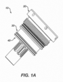
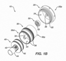
- FIGS. 1A-1C illustrate one embodiment of an anti-fracture expansion device 10 that includes a piston assembly 40 that is slidably disposed within a cylinder or cuff 30 so as to accommodate displaced fluid during a freeze event.
- the illustrated anti-fracture expansion device 10 can also include a cap 20 that is coupled to the cuff 30, and that includes threads 22 on an external surface thereof for threadably mating with threads formed in a bore of a fluid-filled housing.
- the illustrated piston assembly 40 includes a piston 42 and a centering sleeve 44 extending from the piston 42, however a person skilled in the art will appreciate that the sleeve 44 is optional and other centering techniques can be provided.
- the cap 20 can have a variety of configurations, but in general is in the form of a hollow cylindrical housing with a sealed proximal end 20p.
- the cap 20 includes external threads 22 for mating with a threaded bore in a fluid-filled housing, and a cavity 24 for receiving the cuff 30.
- An inner protrusion 26 is configured to mate, e.g., via friction, with an internal lumen 52 of a bearing 50 that is seated within the cavity 24 of the cuff 20.
- the bearing 50 allows the cap 20 to rotate independent of the cuff 30, while still fixing the cuff 30 to the cap 20.
- the piston assembly 40 can have a variety of configurations, but in general has a cylindrical piston head 42 with a central opening 43 extending therethrough.
- the central opening 43 is configured to receive an inner shaft 32 of the cuff 30.
- Internal sealing elements 46 can be disposed therein to form a seal between the central opening 43 of the piston head 42 and the inner shaft 32 of the cuff 30.
- External sealing elements 48 can also be provided around the piston head 42 to form a seal between the outer-facing surface of the piston head 42 and the inside of the cuff 30.
- a sleeve 44 can extend distally from the piston head 42. The sleeve 44, if provided, can facilitate alignment of the piston assembly 40, as will be discussed in more detail below.
- the cuff 30 may not have an inner shaft 32, and the piston head 42 may not have a central opening 43. In that event, the piston head 42 would need to be configured such that it would remain longitudinally aligned during sliding movement within the cuff 30.
- the cuff 30 is generally cylindrical and has a cylindrical cavity 34 formed therein for receiving the piston head 42.
- the cavity 34 is open at the distal end 30d and closed at the proximal end 30p.
- the proximal end 30p can include a recess or cavity 36 that is configured to receive the protrusion 26 formed within the cap 20.
- a bearing assembly 50 can be disposed therebetween for allowing free rotation of the cap 20 relative to the cuff 30.
- the bearing assembly 50 is a radial ball bearing having inner and outer bearing races 51a, 51b with balls 52 therebetween such that the inner and outer bearing races 51a, 51b can rotate independently.
- the outer-facing surface of the outer bearing race 51b can form a friction fit within the cavity 34 at the proximal end 30p of the cuff 30.
- the inner-facing surface of the inner bearing race 51a can similarly form a friction fit with the protrusion 26 within the cap 20, thus mating the two components.
- the bearing assembly 50 thus allows the cap to be rotated to threadably mate with a housing without causing corresponding rotation of the cuff 30.
- the cuff 30 can also include an inner shaft 32 formed therein for slidably receiving the piston assembly 40 therearound, as will be discussed in more detail below.
- a number of external sealing rings 36 e.g., o-ring(s), can be disposed around the cuff 30 to form a seal between the cuff 30 and the fluid-filled housing. Additional sealing rings can be provided to form a seal between the cuff 30 and other components as may be needed.
- a biasing element (not shown) can be disposed between the piston head 42 and the cuff 30, and it can be configured to bias the piston 40 away from the cuff 30 and into a distal position during normal operation.
- the biasing element can be a spring (or equivalent), or alternatively/additionally the assembled device may form a sealed air-tight volume between the piston head 42 and the cuff 30, in which case the air pressure within the assembly would act as a biasing element. If a spring (or equivalent) is used, then the piston head 42 and cuff 30 can form a pressurized volume, but they do not need to, e.g., the cuff could vent to atmosphere.
- the pressure exerted on the piston head 42 by the biasing element may be varied or selected based on fluid pressure variances which may occur during normal operating conditions. Regardless of the configuration of the biasing element, it should apply a force to the piston head 42 that is sufficient to prevent movement of the piston 40 during normal operating conditions, but that allows movement of the piston 40, and thus expansion of the chamber volume, during a freeze event.
- the biasing element provides a pressure in the range of 13.8 bar to 20.7 bar (200 to 300 psi).
- the piston 40 and cuff 30 When fully assembled, the piston 40 and cuff 30 are fully inserted into a fluid filled housing, and the threaded cap 20 is threaded into a bore in the housing to seal the housing.
- the piston 40 will remain in a distal position within the cuff 30, as shown in FIG. 1C , either due to the spring-bias or the pressure within the cuff.
- the force that maintains the piston 40 in the distal position can be designed to be greater than the normal operating pressure of the fluid within the fluid-filled housing to accommodate possible pressure fluctuations.
- fluid within the housing will increase the pressure within the chamber. As the pressure increases and eventually exceeds the force that maintains the piston in the distal position, it will force the piston 40 to move proximally into the cuff 30, thereby expanding the chamber volume and relieving pressure within the housing, thus preventing cracking or other damage to the housing.
- the fluid pressure on the piston 40 will decrease, and the biasing element can move the piston 40 in the distal direction back to its initial position.
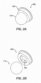
- FIGS. 3A and 3B illustrate one embodiment of a fuel dispenser 200.
- the fuel dispenser 200 generally includes an electronics compartment 210 and a pump compartment 220.
- the electronics compartment 210 houses electronics for facilitating payment for fuel and for facilitating the dispensing of the fuel.
- the electronics include, for example, a fuel controller configured to control dispensing of the fuel from the pump compartment, a communication unit configured to transmit and receive wired and/or wireless communications, a display 212 configured to show information (e.g., media content, payment information, etc.) thereon, a memory configured to store data therein, and a payment terminal (e.g., a card reader, etc.) configured to process customer payment. Only the display 212 is shown in FIGS. 3A and 3B . Similar components can be located on the other side of the electronics compartment 210.
- the pump compartment 220 houses a pump configured to pump fuel from a fuel tank or other reservoir and has therein a fuel meter configured to monitor fuel flow.
- the pump compartment 220 can include other components to facilitate fuel dispensing, such as valves, a strainer/filtering system, a vapor recovery system, etc.
- the pump compartment 220 is isolated from the electronics compartment 210 within the fuel dispenser 200 to facilitate safety, security, and/or maintenance, as will be appreciated by a person skilled in the art. Fuel is thus not allowed to flow from the pump compartment 220 to the electronics compartment 220.
- the fuel dispenser 200 is configured to be connected to the fuel tank or other reservoir containing fuel.
- the fuel When filling up the tank of a motor vehicle, the fuel is pumped from the tank or reservoir by the pump located in the pump compartment 220 and ultimately to a nozzle 216 via a fuel pipe (not shown) and a fuel hose 214.
- a fuel pipe not shown
- a fuel hose 214 When each fuel hose 214 is not in use, the fuel hose 214 hangs along the fuel dispenser 200, and its associated nozzle 216 is seated in a nozzle boot 218.
- the illustrated fuel dispenser 200 is configured to have two hoses 214 and two nozzles 216 on one side of the dispenser 200 and two hoses 214 and two nozzles 216 on the other side of the dispenser 200, but as will be appreciated by a person skilled in the art, the fuel dispenser 200 can include any number of hoses and nozzles. A person skilled in the art will also appreciate that the fuel dispenser can have various other configurations.
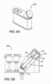
- FIG. 4A illustrates the fuel dispenser 200 of FIGS. 3A and 3B , showing some of the internal components of the pump compartment 220.
- an expansion device can be located in a meter assembly.
- FIG. 4A illustrates one embodiment of a metering assembly 300 disposed within the pump compartment
- FIG. 4B illustrates the metering assembly 300 of FIG. 4A , as well as an additional embodiment of a metering assembly 400.
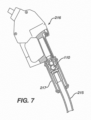
- an expansion device can be disposed within a nozzle 216 of the fuel dispenser 200.
- the anti-fracture expansion devices disclosed herein can be incorporated into any meter assembly known in the art, or into any fluid-filled location within a fuel dispenser that is susceptible to damage due to a freeze event.
- FIGS. 5A-5C illustrate an embodiment of an anti-fracture expansion device employed in a filtering and metering assembly 300 shown in FIG. 4B .
- the expansion device is identical to the device 10 discussed above with respect to FIGS. 1A-1C , however in this embodiment the device 10' includes a fluid delivery shaft 60 and a valve assembly 70 located at the distal end of the shaft.
- the fluid delivery shaft 60 is in the form of an elongate hollow shaft having a proximal end 60p with a threaded protrusion 62 extending proximally therefrom for mating with threads formed within the inner shaft 32 of the cuff 30, which is disposed within the central opening 43 of the piston head 42, thereby fixing the position of the fluid delivery shaft 60 relative to the cuff 30.
- the proximal end 60p can also include several fluid outlets 64 formed therein and spaced around a perimeter thereof for allowing fluid to exit the shaft 60 and to flow into the surrounding chamber. The fluid outlets 64 align with the cutouts in the sleeve 44, though they need not be aligned to permit fluid flow.
- the distal end of the fluid delivery shaft 60 can be configured to couple to the valve assembly, and as shown in FIG. 5C the distal end 60d includes a head 66 formed thereon that is received within a nut 72 of the valve assembly 70.
- the head 66 functions as a sealing ring to form a seal with the nut 72.
- the head 66 can also function to open a valve by pushing against it, which will be discussed below.
- An opening 69 is formed in the head 66 for allowing fluid flow into the inner lumen of the fluid delivery shaft 60.
- a stop flange 68 can be located just proximal of the head 66 for functioning as a stop to control an insertion depth of the head 66 into the nut 72.
- the valve assembly has a nut 72, as mentioned above, that is threaded on the distal portion for threadably mating with a threaded bore in a wall of the fluid-filled housing, i.e., the filter/strainer housing of the meter assembly.
- a valve seal 74 is received within a distal end of the lock nut 72 and is biased proximally toward the closed position.
- the valve assembly is installed into the chamber of a fluid-filled housing via threading or some other means of securing the assembly into the chamber.
- the head 66 on the fluid delivery shaft 60 is inserted into the lock nut 72 such that the sealing rings on the fluid delivery shaft form a seal with the internal wall of the lock nut.
- the cap 20 is threaded into the chamber, the device moves distally until the cap is secure.
- the stop flange 68 on the fluid delivery shaft 60 will abut the lock nut 72. In this position, the head 66 will push the valve seal 74 distally, thereby moving the valve seal 74 from the closed position to an open position.
- Fluid can thus flow past the valve seal 74 and into the fluid delivery shaft 60, which guides the fluid into the chamber in a controlled manner. If the cap is removed, the pressure on the valve seal is released, and the seal will close. This serves as a safety mechanism to prevent unwanted outflow during maintenance operations.
- valve assembly need not include a lock-nut, specifically.
- valve could be connected to a plate that is welded or champed to the chamber.
- fluid enters through the chamber inlet and the valve opening, flows into the distal opening of the fluid delivery shaft 60, traverses the length of the shaft 60, and exits through the fluid outlets 64 in the shaft and the cutouts in the sleeve 44.
- the elongate cut-outs in the sleeve 43 align with the fluid outlets 64 in the fluid delivery shaft 60 to allow fluid to pass therethrough, regardless of the position of the piston assembly 40.
- the fluid may be filtered, treated, stored, etc., as desired.
- a filter or strainer can be disposed within the chamber around the fluid delivery shaft 60 for filtering the fluid as it flows therethrough. Once treatment has been completed, the fluid may be released through an outlet to be passed through a metering system.
- fluid within the housing will increase the pressure within the chamber. As the pressure increases and eventually exceeds the force that maintains the piston in the distal position, it will force the piston to move proximally into the cuff, thereby expanding the chamber volume and relieving pressure within the housing. When the frozen fluid begins to thaw, the fluid pressure on the piston will decrease, and the biasing element can move the piston distally back to its initial position.
Landscapes
- Engineering & Computer Science (AREA)
- Mechanical Engineering (AREA)
- Physics & Mathematics (AREA)
- Mathematical Physics (AREA)
- Theoretical Computer Science (AREA)
- Chemical & Material Sciences (AREA)
- Combustion & Propulsion (AREA)
- Transportation (AREA)
- Infusion, Injection, And Reservoir Apparatuses (AREA)
- Safety Valves (AREA)
- Loading And Unloading Of Fuel Tanks Or Ships (AREA)
- Supply Devices, Intensifiers, Converters, And Telemotors (AREA)
Claims (3)
- Kraftstoffspender (200), der Folgendes umfasst:einen Hydraulikschrank, der darin angeordnete Kraftstoffspendekomponenten aufweist;ein Elektronikfach mit Elektronik, die ausgelegt ist zum Verarbeiten von Bezahlung für durch die Kraftstoffspendekomponenten ausgegebenen Kraftstoff; und zumindest eine Anti-Fraktur-Expansionsvorrichtung (10), intern angeordnet innerhalb einer fluidgefüllten Kammer des Kraftstoffspenders,dadurch gekennzeichnet, dass die Anti-Fraktur-Expansionsvorrichtung (10) eine Kappe (20) umfasst, die einen Kolben (42) aufweist, der gleitbar damit gekoppelt ist und innerhalb der fluidgefüllten Kammer angeordnet ist, wobei der Kolben (42) dazu ausgelegt ist, relativ zur Kappe (20) zu gleiten, wenn der Druck des Fluids innerhalb der fluidgefüllten Kammer den vorbestimmten Schwelldruck überschreitet, um zu ermöglichen, dass sich ein Volumen der fluidgefüllten Kammer vergrößert.
- Kraftstoffspender (200) nach Anspruch 1, wobei die fluidgefüllte Kammer einen Fluideinlass und einen Fluidauslass umfasst, und wobei die Anti-Fraktur-Expansionsvorrichtung (10) dazu ausgelegt ist, Fluidströmung durch einen aus dem Fluideinlass und dem Fluidauslass zu steuern.
- Kraftstoffspender (200) nach Anspruch 1, wobei die Anti-Fraktur-Expansionsvorrichtung (10) ein innerhalb eines Fluideinlasses der fluidgefüllten Kammer angeordnetes Rückschlagventil in einer offenen Position hält, um Fluid zu ermöglichen, in die fluidgefüllte Kammer zu strömen.
Priority Applications (1)
| Application Number | Priority Date | Filing Date | Title |
|---|---|---|---|
| EP24206035.8A EP4467511A3 (de) | 2016-10-26 | 2017-10-24 | Vorrichtung zur erweiterung gegen bruch |
Applications Claiming Priority (3)
| Application Number | Priority Date | Filing Date | Title |
|---|---|---|---|
| US15/334,521 US10538425B2 (en) | 2016-10-26 | 2016-10-26 | Anti-fracture expansion device |
| PCT/US2017/058016 WO2018081071A2 (en) | 2016-10-26 | 2017-10-24 | Anti-fracture expansion device |
| EP17795142.3A EP3532329B1 (de) | 2016-10-26 | 2017-10-24 | Vorrichtung zur vermeidung des bruchs eines behälters mit dehnbarer flüssigkeit |
Related Parent Applications (2)
| Application Number | Title | Priority Date | Filing Date |
|---|---|---|---|
| EP17795142.3A Division-Into EP3532329B1 (de) | 2016-10-26 | 2017-10-24 | Vorrichtung zur vermeidung des bruchs eines behälters mit dehnbarer flüssigkeit |
| EP17795142.3A Division EP3532329B1 (de) | 2016-10-26 | 2017-10-24 | Vorrichtung zur vermeidung des bruchs eines behälters mit dehnbarer flüssigkeit |
Related Child Applications (1)
| Application Number | Title | Priority Date | Filing Date |
|---|---|---|---|
| EP24206035.8A Division EP4467511A3 (de) | 2016-10-26 | 2017-10-24 | Vorrichtung zur erweiterung gegen bruch |
Publications (3)
| Publication Number | Publication Date |
|---|---|
| EP3604205A1 EP3604205A1 (de) | 2020-02-05 |
| EP3604205B1 true EP3604205B1 (de) | 2024-10-16 |
| EP3604205C0 EP3604205C0 (de) | 2024-10-16 |
Family
ID=60269955
Family Applications (3)
| Application Number | Title | Priority Date | Filing Date |
|---|---|---|---|
| EP24206035.8A Pending EP4467511A3 (de) | 2016-10-26 | 2017-10-24 | Vorrichtung zur erweiterung gegen bruch |
| EP17795142.3A Active EP3532329B1 (de) | 2016-10-26 | 2017-10-24 | Vorrichtung zur vermeidung des bruchs eines behälters mit dehnbarer flüssigkeit |
| EP19197486.4A Active EP3604205B1 (de) | 2016-10-26 | 2017-10-24 | Kraftstoffspender mit anti-fraktur-expansionsvorrichtung |
Family Applications Before (2)
| Application Number | Title | Priority Date | Filing Date |
|---|---|---|---|
| EP24206035.8A Pending EP4467511A3 (de) | 2016-10-26 | 2017-10-24 | Vorrichtung zur erweiterung gegen bruch |
| EP17795142.3A Active EP3532329B1 (de) | 2016-10-26 | 2017-10-24 | Vorrichtung zur vermeidung des bruchs eines behälters mit dehnbarer flüssigkeit |
Country Status (6)
| Country | Link |
|---|---|
| US (2) | US10538425B2 (de) |
| EP (3) | EP4467511A3 (de) |
| CN (1) | CN110177705A (de) |
| ES (2) | ES3004558T3 (de) |
| PT (1) | PT3532329T (de) |
| WO (1) | WO2018081071A2 (de) |
Families Citing this family (2)
| Publication number | Priority date | Publication date | Assignee | Title |
|---|---|---|---|---|
| US10538425B2 (en) | 2016-10-26 | 2020-01-21 | Wayne Fueling Systems Llc | Anti-fracture expansion device |
| KR102855194B1 (ko) * | 2020-08-04 | 2025-09-03 | 현대자동차주식회사 | 차량용 요소수 캡 조립체 및 이를 포함하는 요소수 공급 시스템 |
Family Cites Families (14)
| Publication number | Priority date | Publication date | Assignee | Title |
|---|---|---|---|---|
| US4972972A (en) * | 1989-09-11 | 1990-11-27 | Goguen Daniel J | Portable fuel dispensing container |
| US5234036A (en) * | 1991-03-04 | 1993-08-10 | Amoco Corporation | Dispensing fuel with aspiration of condensed vapors |
| US5259424A (en) * | 1991-06-27 | 1993-11-09 | Dvco, Inc. | Method and apparatus for dispensing natural gas |
| US6203117B1 (en) * | 1997-10-20 | 2001-03-20 | Kelsey-Hayes Corporation | Compensator assembly in a hydraulic control unit for vehicular brake systems |
| US6913046B2 (en) * | 2002-10-24 | 2005-07-05 | Gilbarco Inc. | Fuel dispenser shear valve assembly |
| DE10249750B4 (de) * | 2002-10-25 | 2014-11-06 | Cummins Ltd. | Ausgleichsvorrichtung zur Aufnahme der Volumenausdehnung von Medien, insbesondere einer Harnstoff-Wasser-Lösung, beim Einfrieren |
| DE10362140C5 (de) | 2003-12-29 | 2015-10-08 | Cummins Ltd. | Gefriertaugliche Abgasnachbehandlungseinrichtung für ein Kraftfahrzeug |
| US7264142B2 (en) * | 2004-01-27 | 2007-09-04 | Medical Instill Technologies, Inc. | Dispenser having variable-volume storage chamber and depressible one-way valve assembly for dispensing creams and other substances |
| FR2899136B1 (fr) * | 2006-03-29 | 2008-07-04 | Airlessystems Soc Par Actions | Dispositif de distribution de produit fluide |
| US8376185B2 (en) * | 2009-08-05 | 2013-02-19 | Gilbarco Inc. | System and method for fraud detection and shut-off at a fuel dispenser |
| FR2967141B1 (fr) * | 2010-11-04 | 2014-02-21 | Valois Sas | Tete de distribution de produit fluide et distributeur comprenant une telle tete de distribution. |
| CA2844894A1 (en) * | 2013-03-15 | 2014-09-15 | Bpc Acquisition Company | Fuel dispensers |
| CN106029551B (zh) * | 2014-02-26 | 2018-01-02 | 艾登蒂克股份公司 | 分配枪 |
| US10538425B2 (en) * | 2016-10-26 | 2020-01-21 | Wayne Fueling Systems Llc | Anti-fracture expansion device |
-
2016
- 2016-10-26 US US15/334,521 patent/US10538425B2/en active Active
-
2017
- 2017-10-24 ES ES19197486T patent/ES3004558T3/es active Active
- 2017-10-24 EP EP24206035.8A patent/EP4467511A3/de active Pending
- 2017-10-24 ES ES17795142T patent/ES2834328T3/es active Active
- 2017-10-24 WO PCT/US2017/058016 patent/WO2018081071A2/en not_active Ceased
- 2017-10-24 EP EP17795142.3A patent/EP3532329B1/de active Active
- 2017-10-24 PT PT177951423T patent/PT3532329T/pt unknown
- 2017-10-24 CN CN201780065594.6A patent/CN110177705A/zh active Pending
- 2017-10-24 EP EP19197486.4A patent/EP3604205B1/de active Active
-
2020
- 2020-01-17 US US16/746,245 patent/US11286155B2/en active Active
Also Published As
| Publication number | Publication date |
|---|---|
| ES3004558T3 (en) | 2025-03-12 |
| CN110177705A (zh) | 2019-08-27 |
| US10538425B2 (en) | 2020-01-21 |
| EP3532329B1 (de) | 2020-08-26 |
| EP4467511A3 (de) | 2025-01-22 |
| WO2018081071A3 (en) | 2018-06-21 |
| US11286155B2 (en) | 2022-03-29 |
| EP4467511A2 (de) | 2024-11-27 |
| US20200148529A1 (en) | 2020-05-14 |
| WO2018081071A2 (en) | 2018-05-03 |
| ES2834328T3 (es) | 2021-06-17 |
| EP3532329A2 (de) | 2019-09-04 |
| EP3604205A1 (de) | 2020-02-05 |
| US20180111819A1 (en) | 2018-04-26 |
| PT3532329T (pt) | 2020-11-26 |
| EP3604205C0 (de) | 2024-10-16 |
Similar Documents
| Publication | Publication Date | Title |
|---|---|---|
| US5039284A (en) | Fuel pump with a vapor vent valve | |
| EP3604205B1 (de) | Kraftstoffspender mit anti-fraktur-expansionsvorrichtung | |
| JP2604995B2 (ja) | 加圧流体用高速連結装置 | |
| US3604446A (en) | Valve | |
| US9121334B2 (en) | Oil jet | |
| US20180038358A1 (en) | Systems and methods for purging an exhaust reductant delivery system | |
| RU2302273C2 (ru) | Клапанный элемент | |
| CN102027284B (zh) | 加压气体分配装置、包括这种装置和控制装置的组件以及设有这种分配装置的容器 | |
| KR20180033534A (ko) | 분사 밸브, 배기가스 후처리 시스템 | |
| US8807180B2 (en) | Dual fluid fueling nozzle | |
| US11719373B2 (en) | Coupling with pressure relief | |
| US11125372B2 (en) | Coupling, and method for transferring fluids | |
| JPS6316312B2 (de) | ||
| US5911562A (en) | High pressure fluid delivery system with automatic priming valve | |
| US20150321836A1 (en) | Receiver for reductant tank | |
| JP5000834B2 (ja) | 車両エンジン用のコモンレール式ガソリン燃料噴射装置 | |
| CN101415978B (zh) | 限压装置 | |
| RU2068304C1 (ru) | Устройство для впрыска жидкости в сжатый газ | |
| CN109282065B (zh) | 一种换向阀 | |
| KR100707759B1 (ko) | 가압 펌프를 지닌 고압 유체 용기 구조 | |
| EP3516289B1 (de) | Sicherheitsventil mit metallelementen für eine gaskassette | |
| US6722131B1 (en) | Fuel control valve | |
| EP2256392A1 (de) | Ventilanordnung | |
| US2311078A (en) | Engine primer | |
| JP2004514999A (ja) | 予め調整されていて使用者が変更できない固定圧力を有する流体用膨張バルブアセンブリ |
Legal Events
| Date | Code | Title | Description |
|---|---|---|---|
| PUAI | Public reference made under article 153(3) epc to a published international application that has entered the european phase |
Free format text: ORIGINAL CODE: 0009012 |
|
| STAA | Information on the status of an ep patent application or granted ep patent |
Free format text: STATUS: THE APPLICATION HAS BEEN PUBLISHED |
|
| AC | Divisional application: reference to earlier application |
Ref document number: 3532329 Country of ref document: EP Kind code of ref document: P |
|
| AK | Designated contracting states |
Kind code of ref document: A1 Designated state(s): AL AT BE BG CH CY CZ DE DK EE ES FI FR GB GR HR HU IE IS IT LI LT LU LV MC MK MT NL NO PL PT RO RS SE SI SK SM TR |
|
| AX | Request for extension of the european patent |
Extension state: BA ME |
|
| STAA | Information on the status of an ep patent application or granted ep patent |
Free format text: STATUS: REQUEST FOR EXAMINATION WAS MADE |
|
| 17P | Request for examination filed |
Effective date: 20200709 |
|
| RBV | Designated contracting states (corrected) |
Designated state(s): AL AT BE BG CH CY CZ DE DK EE ES FI FR GB GR HR HU IE IS IT LI LT LU LV MC MK MT NL NO PL PT RO RS SE SI SK SM TR |
|
| STAA | Information on the status of an ep patent application or granted ep patent |
Free format text: STATUS: EXAMINATION IS IN PROGRESS |
|
| 17Q | First examination report despatched |
Effective date: 20220311 |
|
| GRAP | Despatch of communication of intention to grant a patent |
Free format text: ORIGINAL CODE: EPIDOSNIGR1 |
|
| STAA | Information on the status of an ep patent application or granted ep patent |
Free format text: STATUS: GRANT OF PATENT IS INTENDED |
|
| INTG | Intention to grant announced |
Effective date: 20240515 |
|
| GRAS | Grant fee paid |
Free format text: ORIGINAL CODE: EPIDOSNIGR3 |
|
| GRAA | (expected) grant |
Free format text: ORIGINAL CODE: 0009210 |
|
| STAA | Information on the status of an ep patent application or granted ep patent |
Free format text: STATUS: THE PATENT HAS BEEN GRANTED |
|
| AC | Divisional application: reference to earlier application |
Ref document number: 3532329 Country of ref document: EP Kind code of ref document: P |
|
| AK | Designated contracting states |
Kind code of ref document: B1 Designated state(s): AL AT BE BG CH CY CZ DE DK EE ES FI FR GB GR HR HU IE IS IT LI LT LU LV MC MK MT NL NO PL PT RO RS SE SI SK SM TR |
|
| REG | Reference to a national code |
Ref country code: GB Ref legal event code: FG4D |
|
| REG | Reference to a national code |
Ref country code: CH Ref legal event code: EP |
|
| REG | Reference to a national code |
Ref country code: IE Ref legal event code: FG4D |
|
| REG | Reference to a national code |
Ref country code: DE Ref legal event code: R096 Ref document number: 602017085593 Country of ref document: DE |
|
| U01 | Request for unitary effect filed |
Effective date: 20241114 |
|
| U07 | Unitary effect registered |
Designated state(s): AT BE BG DE DK EE FI FR IT LT LU LV MT NL PT RO SE SI Effective date: 20241121 |
|
| U20 | Renewal fee for the european patent with unitary effect paid |
Year of fee payment: 8 Effective date: 20241127 |
|
| REG | Reference to a national code |
Ref country code: ES Ref legal event code: FG2A Ref document number: 3004558 Country of ref document: ES Kind code of ref document: T3 Effective date: 20250312 |
|
| PG25 | Lapsed in a contracting state [announced via postgrant information from national office to epo] |
Ref country code: HR Free format text: LAPSE BECAUSE OF FAILURE TO SUBMIT A TRANSLATION OF THE DESCRIPTION OR TO PAY THE FEE WITHIN THE PRESCRIBED TIME-LIMIT Effective date: 20241016 Ref country code: IS Free format text: LAPSE BECAUSE OF FAILURE TO SUBMIT A TRANSLATION OF THE DESCRIPTION OR TO PAY THE FEE WITHIN THE PRESCRIBED TIME-LIMIT Effective date: 20250216 |
|
| PG25 | Lapsed in a contracting state [announced via postgrant information from national office to epo] |
Ref country code: NO Free format text: LAPSE BECAUSE OF FAILURE TO SUBMIT A TRANSLATION OF THE DESCRIPTION OR TO PAY THE FEE WITHIN THE PRESCRIBED TIME-LIMIT Effective date: 20250116 |
|
| PG25 | Lapsed in a contracting state [announced via postgrant information from national office to epo] |
Ref country code: GR Free format text: LAPSE BECAUSE OF FAILURE TO SUBMIT A TRANSLATION OF THE DESCRIPTION OR TO PAY THE FEE WITHIN THE PRESCRIBED TIME-LIMIT Effective date: 20250117 |
|
| PG25 | Lapsed in a contracting state [announced via postgrant information from national office to epo] |
Ref country code: PL Free format text: LAPSE BECAUSE OF FAILURE TO SUBMIT A TRANSLATION OF THE DESCRIPTION OR TO PAY THE FEE WITHIN THE PRESCRIBED TIME-LIMIT Effective date: 20241016 |
|
| PG25 | Lapsed in a contracting state [announced via postgrant information from national office to epo] |
Ref country code: RS Free format text: LAPSE BECAUSE OF FAILURE TO SUBMIT A TRANSLATION OF THE DESCRIPTION OR TO PAY THE FEE WITHIN THE PRESCRIBED TIME-LIMIT Effective date: 20250116 |
|
| REG | Reference to a national code |
Ref country code: CH Ref legal event code: PL |
|
| PG25 | Lapsed in a contracting state [announced via postgrant information from national office to epo] |
Ref country code: SM Free format text: LAPSE BECAUSE OF FAILURE TO SUBMIT A TRANSLATION OF THE DESCRIPTION OR TO PAY THE FEE WITHIN THE PRESCRIBED TIME-LIMIT Effective date: 20241016 |
|
| PG25 | Lapsed in a contracting state [announced via postgrant information from national office to epo] |
Ref country code: MC Free format text: LAPSE BECAUSE OF FAILURE TO SUBMIT A TRANSLATION OF THE DESCRIPTION OR TO PAY THE FEE WITHIN THE PRESCRIBED TIME-LIMIT Effective date: 20241016 |
|
| PG25 | Lapsed in a contracting state [announced via postgrant information from national office to epo] |
Ref country code: CH Free format text: LAPSE BECAUSE OF NON-PAYMENT OF DUE FEES Effective date: 20241031 |
|
| PG25 | Lapsed in a contracting state [announced via postgrant information from national office to epo] |
Ref country code: SK Free format text: LAPSE BECAUSE OF FAILURE TO SUBMIT A TRANSLATION OF THE DESCRIPTION OR TO PAY THE FEE WITHIN THE PRESCRIBED TIME-LIMIT Effective date: 20241016 |
|
| PLBE | No opposition filed within time limit |
Free format text: ORIGINAL CODE: 0009261 |
|
| STAA | Information on the status of an ep patent application or granted ep patent |
Free format text: STATUS: NO OPPOSITION FILED WITHIN TIME LIMIT |
|
| 26N | No opposition filed |
Effective date: 20250717 |
|
| PG25 | Lapsed in a contracting state [announced via postgrant information from national office to epo] |
Ref country code: IE Free format text: LAPSE BECAUSE OF NON-PAYMENT OF DUE FEES Effective date: 20241024 |
|
| U20 | Renewal fee for the european patent with unitary effect paid |
Year of fee payment: 9 Effective date: 20251027 |
|
| PGFP | Annual fee paid to national office [announced via postgrant information from national office to epo] |
Ref country code: GB Payment date: 20251023 Year of fee payment: 9 |
|
| PGFP | Annual fee paid to national office [announced via postgrant information from national office to epo] |
Ref country code: CZ Payment date: 20251017 Year of fee payment: 9 |
|
| PG25 | Lapsed in a contracting state [announced via postgrant information from national office to epo] |
Ref country code: CY Free format text: LAPSE BECAUSE OF FAILURE TO SUBMIT A TRANSLATION OF THE DESCRIPTION OR TO PAY THE FEE WITHIN THE PRESCRIBED TIME-LIMIT; INVALID AB INITIO Effective date: 20171024 |
|
| PGFP | Annual fee paid to national office [announced via postgrant information from national office to epo] |
Ref country code: ES Payment date: 20251118 Year of fee payment: 9 |
|
| PG25 | Lapsed in a contracting state [announced via postgrant information from national office to epo] |
Ref country code: HU Free format text: LAPSE BECAUSE OF FAILURE TO SUBMIT A TRANSLATION OF THE DESCRIPTION OR TO PAY THE FEE WITHIN THE PRESCRIBED TIME-LIMIT; INVALID AB INITIO Effective date: 20171024 |