EP2256392A1 - Ventilanordnung - Google Patents
Ventilanordnung Download PDFInfo
- Publication number
- EP2256392A1 EP2256392A1 EP20090007191 EP09007191A EP2256392A1 EP 2256392 A1 EP2256392 A1 EP 2256392A1 EP 20090007191 EP20090007191 EP 20090007191 EP 09007191 A EP09007191 A EP 09007191A EP 2256392 A1 EP2256392 A1 EP 2256392A1
- Authority
- EP
- European Patent Office
- Prior art keywords
- valve
- pressure
- outlet
- valve element
- pressure chamber
- Prior art date
- Legal status (The legal status is an assumption and is not a legal conclusion. Google has not performed a legal analysis and makes no representation as to the accuracy of the status listed.)
- Granted
Links
- XLYOFNOQVPJJNP-UHFFFAOYSA-N water Substances O XLYOFNOQVPJJNP-UHFFFAOYSA-N 0.000 description 46
- 239000012530 fluid Substances 0.000 description 5
- 238000010276 construction Methods 0.000 description 3
- 230000001627 detrimental effect Effects 0.000 description 1
- 239000007788 liquid Substances 0.000 description 1
- 239000003595 mist Substances 0.000 description 1
- 230000000284 resting effect Effects 0.000 description 1
- 238000007789 sealing Methods 0.000 description 1
- 239000008400 supply water Substances 0.000 description 1
Images


Classifications
-
- F—MECHANICAL ENGINEERING; LIGHTING; HEATING; WEAPONS; BLASTING
- F16—ENGINEERING ELEMENTS AND UNITS; GENERAL MEASURES FOR PRODUCING AND MAINTAINING EFFECTIVE FUNCTIONING OF MACHINES OR INSTALLATIONS; THERMAL INSULATION IN GENERAL
- F16K—VALVES; TAPS; COCKS; ACTUATING-FLOATS; DEVICES FOR VENTING OR AERATING
- F16K31/00—Actuating devices; Operating means; Releasing devices
- F16K31/12—Actuating devices; Operating means; Releasing devices actuated by fluid
- F16K31/36—Actuating devices; Operating means; Releasing devices actuated by fluid in which fluid from the circuit is constantly supplied to the fluid motor
- F16K31/40—Actuating devices; Operating means; Releasing devices actuated by fluid in which fluid from the circuit is constantly supplied to the fluid motor with electrically-actuated member in the discharge of the motor
- F16K31/406—Actuating devices; Operating means; Releasing devices actuated by fluid in which fluid from the circuit is constantly supplied to the fluid motor with electrically-actuated member in the discharge of the motor acting on a piston
-
- Y—GENERAL TAGGING OF NEW TECHNOLOGICAL DEVELOPMENTS; GENERAL TAGGING OF CROSS-SECTIONAL TECHNOLOGIES SPANNING OVER SEVERAL SECTIONS OF THE IPC; TECHNICAL SUBJECTS COVERED BY FORMER USPC CROSS-REFERENCE ART COLLECTIONS [XRACs] AND DIGESTS
- Y10—TECHNICAL SUBJECTS COVERED BY FORMER USPC
- Y10T—TECHNICAL SUBJECTS COVERED BY FORMER US CLASSIFICATION
- Y10T137/00—Fluid handling
- Y10T137/7722—Line condition change responsive valves
- Y10T137/7837—Direct response valves [i.e., check valve type]
Definitions
- the invention concerns a valve arrangement comprising a flow path connecting an inlet and an outlet, a closing means arranged in said flow path, a resetting means and a first pressure in a first pressure chamber acting in a closing direction on said closing means, a pressure of said outlet and a second pressure in a second pressure chamber corresponding to a pressure of said inlet when said closing means is closed acting in opening direction on said closing means, said first pressure chamber being connectable to the outlet via an auxiliary valve.
- Such a valve arrangement is known from WO 2005/031202 A1 .
- the closing means forms a pilot controlled valve means.
- a valve means is particularly used in connection with a control of water, which is exposed to a high pressure.
- Applications are, for example, snow generating devices and moistening devices.
- a snow generating device is used as example for illustrating the present invention.
- the invention is not limited to a valve arrangement in connection with a snow generating device.
- a snow generating devices uses water which is supplied with a rather high pressure of 20 to 120 bar. This water is atomised and sprayed into cold air in order to produce snow. When the snow generating device is not in use, it must be emptied in order to avoid damages caused by frozen water.
- the valve arrangement When the operation of the snow generating device starts, the valve arrangement is opened by actuating the pilot valve. However, since the water is supplied to the empty snow generating device with the above mentioned high pressure in the range of 20 to 120 bar, a pressure pulse is generated in the snow generating device which can be detrimental.
- the invention is based on the task to keep a pressure pulse small when opening the valve arrangement.
- this task is solved in that said closing means having a first opening state and a second opening state, a flow resistance of said closing means in said first opening state being larger than a flow resistance of said closing means in said second opening state.
- the flow resistance of the closing device in the second opening state is far lower than in the first opening state.
- a permanent supply of water under high pressure is required.
- the supply can be realised since the closing device in the second opening state has only a rather low flow resistance.
- any other suitable hydraulic fluid can be used. In the following the invention is illustrated using water as an example of an hydraulic fluid. However, the invention is not limited to water as hydraulic fluid.
- the second opening state of said closing means is established by a pressure at the outlet which exceeds a predetermined value.
- the valve arrangement is self-controlled. The water supplied to the snow generating device fills the snow generating device increasing the pressure at the outlet. When the predetermined pressure value is reached, the valve arrangement "knows" that it now can fully open and supply water without having the risk of a strong pressure pulse in an empty system.
- said resetting means comprises at least a spring.
- a spring is a rather simple embodiment of a resetting means. It has the advantage that the spring force increases when the spring is compressed. This characteristic can be used to establish the different opening degrees or opening states of the closing means.
- said closing means comprises at least a first valve element and a second valve element.
- Using at least two valve elements gives a rather simple construction of the valve arrangement in which two different opening conditions can be established.
- said first pressure chamber and said second pressure chamber are connected via an orifice running through said first valve element.
- water is supplied from the second pressure chamber to the first pressure chamber. It is therefore possible to create a sufficient pressure in the first pressure chamber to move the first valve element from an opening position to a closing position in case the valve arrangement should close. Since the orifice is arranged in the valve element it is not possible that this orifice is closed by a movement of said first valve element.
- the first valve element together with a first valve seat forms a valve means
- the second valve element together with a second valve seat forms a throttling means and the valve means and the throttling means are connected in series.
- the valve means opens, the flow of water is restricted by the throttling means. Only when the throttling means opens too, the flow of water is almost unrestricted. This is a rather simple construction of the valve arrangement.
- said first valve element is slidingly arranged around said second valve element, said second valve element protrudes through said first valve seat, and said second valve seat is formed by a ring bearing said first valve seat.
- a gap between the second valve element and the second valve seat forms the throttling means. It is possible to determine the throttling characteristics of this throttling means by forming the second valve element and/or the second valve seat with corresponding geometries.
- a first spring acts on said first valve element and a second spring acts on said second valve element.
- the closing means it is possible to make the closing means so that the movement of the first valve element requires a smaller force than the movement of the second valve element. Since the second valve element moves in opening direction under the control of the pressure at the outlet, the second spring can be dimensioned depending on the predetermined pressure at which the closing device should be brought into the second opening state.
- said second valve element comprises a moving restrictor stopping a movement of said second valve element in closing direction.
- a moving restrictor can be made by a step or any other protrusion abutting against a part of the housing in which the second valve element is arranged.
- Such a second valve element can be positioned in the second valve seat with a rather high precision.
- said first pressure chamber is connected with said outlet via a second orifice
- said second valve element together with a second valve seat is forming a second valve means arranged parallel to said second orifice. Since the second pressure chamber and the first pressure chamber are connected via the first orifice, the first orifice and the second orifice form a pressure divider when the auxiliary valve is opened. This means that in the first pressure chamber a pressure is established which is between the pressure at the inlet and the pressure at the outlet. This "medium" pressure acts in closing direction on the first valve element so that the first valve element is moved only a short distance away from the first valve seat until this medium pressure together with the force of the resetting means has an equilibrium to the force generated by the pressure of the outlet.
- said second valve element is actuatable by a pressure at said outlet.
- the second valve is opened connecting automatically the first pressure chamber with the outlet so that the closing means is automatically moved to the fully opened state.
- a third valve means is arranged between said inlet and said outlet opening a restricted flow passage when it is loaded by said first pressure in said first pressure chamber which loading is controlled by said auxiliary valve.
- the third valve means is a kind of pre-filling means by which water (or like in all other embodiments any other fluid) can flow from the inlet to the outlet without causing a pressure pulse in the empty outlet. This allows a controlled increase of the pressure in the outlet.
- the closing means can fully open to supply the outlet and the snow generating device with the required flow of water.
- said second valve element opens a passage between the first pressure chamber and said outlet when the pressure at said outlet exceeds a predetermined value.
- the second valve element is opened automatically when the outlet and the snow generating device are filled sufficiently with water so that a pressure pulse in an empty or only partly filled system can be avoided.
- the first valve element can be moved away from the first valve seat since the pressure in the first pressure chamber is sufficiently low and the pressure at the inlet acts in opening direction on the first valve element. No further action from the outside is required.
- Fig. 1 shows an hydraulic circuit 1 supplying a snow generating device 2 with water under high pressure.
- the snow generating device 2 comprises nozzles 2a through which the water is outputted generating water droplets or a water mist. Therefore, in operation the snow generating device has a permanent water requirement.
- a pump 3 driven by a motor 4 generates a pressure in the range of 20 bar or more. The pressure is limited by a safety valve 5 having an opening pressure of 110 bar for example. When the safety valve 5 opens, water is drained to a tank 6.
- the pump 3 can be replaced by any other pressure generating device, e.g. a tank or a reservoir being arranged higher than the snow generating device 2.
- the snow generating device 2 is connected to the pump 3 via a valve arrangement 7. Furthermore, it is connected to the tank 6 via a draining valve 8. When the snow generating device is not in use, the draining valve 8 is opened to let the water come out in order to avoid damages by frozen water in the snow generating device.
- the valve arrangement 7 comprises an inlet 9 and an outlet 10 which are connected by a flow path 11.
- a closing means 12 is arranged in said flow path 11, said closing means having a fully closed condition. This condition is shown in the Fig. Furthermore, said closing means has a first opening state A and a second opening state B. The flow resistance of said closing means 12 in said first opening state A is larger than the flow resistance of the said closing means 12 in said second opening state B. In other words, the closing means 12 is fully opened in the second opening state B and partly opened in the said first opening state A.
- Fig. 1B shows the pressure P over the time t at the outlet. Pressure P1 is the outlet pressure of pump 3. From time t1 to time t2 the closing means 12 is only partly opened so that the pressure can only increase slowly from zero to a pressure P2. At time t2 the closing means 12 is opened to the fully opened condition B so that the pressure is rapidly increased to a pressure value P3. This pressure value P3 is maintained constant until the closing means 12 is fully closed.
- the increase from pressure P2 to pressure P3 is performed when the snow generating device 2 is completely or almost completely filled with water so that no air or only small volumes of air are compressed by the incoming water. From time t2 to time t3 water is supplied with sufficient pressure and sufficient flow in order to enable the snow generating device 2 to produce snow.
- an auxiliary valve 13 is arranged between the inlet 9 and the outlet 10 parallel to the closing means 12.
- a first pressure chamber 14 is connected via a first orifice 15 with the inlet 9. Therefore, when the closing means 12 is closed, in the first pressure chamber 14 there is a first pressure corresponding to the pressure at the inlet 9. This first pressure in said first pressure chamber 14 acts in closing direction on said closing means 12.
- a resetting means in form of a spring 16 also acts in closing direction on said closing means 12.
- the first pressure chamber 14 is connected to the outlet 10 via the auxiliary valve 13 and a second orifice 17.
- the first pressure in said first pressure chamber 14 will be an intermediate pressure between the pressure at said inlet 9 and said outlet 10.
- Said inlet 9 is connected to a second pressure chamber 18.
- the pressure in said pressure chamber 18 (“the second pressure") acts in opening direction on the closing means 12.
- the outlet 10 is connected to a third pressure chamber 19. Therefore, the pressure at the outlet 10 acts in opening direction on said closing device 12.
- the auxiliary valve 13 When the auxiliary valve 13 is closed, the first pressure in the first pressure chamber 14 together with the resetting means (spring 16) move the closing means 12 in fully closed condition. No further water is supplied to the snow generating device 2.
- the snow generating device 2 can be emptied via the draining valve 8.
- the draining valve 8 When the snow generating device 2 is started, the draining valve 8 is closed. The auxiliary valve 13 is opened. The first pressure in the first pressure chamber 14 is lowered via the second orifice 17. The pressure difference between the second pressure chamber 18 and the first pressure chamber 14 exceeds the force of the spring 16, so that the closing means 12 is moved into the first opening state A, i.e. into a partly opened condition. A further movement is not possible at this moment since the closing means 12 is stopped by a stop 20 which is supported by a second spring 21.
- the auxiliary valve 13 closes.
- the first pressure in the first pressure chamber 14 increases to the outlet pressure P1 of the pump.
- the effective pressure area in the first pressure chamber 14 is larger than the effective area in the second pressure chamber 18. Therefore, the closing means 12 is closed.
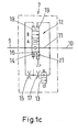
- Fig. 1c shows a slightly modified valve arrangement 7 in which a chamber in which the second spring 21 is arranged is open to atmosphere. All other elements are the same.
- Fig. 2 to 5 show a first embodiment of said valve arrangement 7 with more details.
- the inlet 9 and the outlet 10 are arranged in a housing 22 forming a first valve seat 23 and a second valve seat 24.
- the second valve seat 24 is formed at the radial inner part of a ring section 25 of the housing 22 bearing the first valve seat 23.
- a first valve element 26 together with said first valve seat 23 form a valve means.
- the valve arrangement 7 is fully closed.
- a second valve element 27 protrudes through said second valve seat 24 and together with said second valve seat 24 form a throttling means. In other words, there is a small gap between the second valve element 27 and the second valve seat 24.
- the inlet 9 is connected to the second pressure chamber 18.
- the outlet 10 is connected to the first pressure chamber 14 via the auxiliary valve 13.
- the auxiliary valve 13 comprises an electromagnet 28.
- the auxiliary valve 13 is arranged in a channel 29 connecting the second pressure chamber 18 and the outlet 10.
- the first spring 16 acts on the first valve element 26 in closing direction.
- the second spring 21 acts on the second valve element 27 in closing direction.
- the second valve element 27 comprises a moving restrictor 30 bearing against the housing 22 when the throttling means exhibits the largest flow restriction.
- the second spring 21 is arranged in a spring chamber which opens to atmosphere.
- the second spring 21 is a resetting means.
- other means can be used to generate a resetting force, e.g. an external fluid pressure (liquid or gas), a motor or a lever loaded from the outside.
- the pressure in the first pressure chamber 14 acts on a first pressure area 31.
- the pressure in the second pressure chamber 18 acts on a second pressure area 32.
- the second pressure area 32 is larger than the first pressure area 31.
- the first valve element 26 is slidingly arranged around the second valve element 27, i.e. it forms a hollow cylinder, the inner diameter of which corresponds to the outer diameter of the second valve element 27. Sealing means 33 are provided to prevent a flow of water between the first valve element 26 and the second valve element 27.
- An orifice 34 is provided in the first valve element 26 connecting the first pressure chamber 14 and the second pressure chamber 18, i.e. the first pressure chamber 14 and the inlet 9. This orifice 34 corresponds to the orifice 15 of Fig. 1 .
- valve arrangement 7 The operation of this valve arrangement 7 is explained in connection with Figs. 2 to 5 .
- the flow of water from the inlet 9 to the outlet 10 is restricted by the throttling means formed by the second valve element 27 and the second valve seat 24, i.e. the water flows through a gap between the second valve element 27 and the second valve seat 24.
- This gap can be shaped ring-like having a radial thickness of 15/100 mm, for example. It may be smaller or larger depending on the application and the desired flow restriction.
- the throttling characteristic of this throttling means can be adjusted by designing the form of the second valve seat 24 and the form of the second vale element 27.
- the first pressure chamber 14 receives permanently water from the inlet 9 via the orifice 34. However, this water escapes through the channel 29 to the outlet 10 as long as the auxiliary valve 13 is open.
- Fig. 6 shows a second embodiment of a valve arrangement 7 in which like elements as in Fig. 1 to 5 are designated with the same numerals.
- valve arrangement 7 In the condition shown the valve arrangement 7 is fully closed.
- the first valve element 26 together with the first valve seat 23 seal a connection between the inlet 9 and the outlet 10.
- the first pressure chamber 14 is connected via a second orifice 35 and the auxiliary valve 13 to the outlet 10.
- the first pressure in the first pressure chamber 14 equals the pressure at the inlet 9.
- the pressure at the outlet 10 is almost zero.
- the first pressure area 31 is much larger than the second pressure area 32.
- the auxiliary valve 13 opens, a flow is established between the inlet 9 and the outlet 10 via the two orifices 34, 35. Therefore, the first pressure in the first pressure chamber 14 drops to an intermediate value between the pressure at the inlet 9 and the pressure at the outlet 10.
- the orifices 34, 35 are so designed that the force difference over the first valve element 26 which is generated by the pressure in the first pressure chamber 14 acting on the first pressure area 31 and the pressure in the second pressure chamber 18 acting on the second pressure 32 exceeds slightly the force of the first spring 16.
- the force difference is only slightly larger than the force of the first spring 26. Therefore, an equilibrium is reached when the first valve element 26 is moved away from the first valve seat 23 by a small distance in the range of a few millimetres or less. In this condition, a restricted flow from the inlet 9 to the outlet 10 is possible. This flow increases the pressure at the outlet 10.
- the second valve element 27 together with the second valve seat 24 form a second valve means which is arranged parallel to the second orifice 35.
- the second valve element 27 is forced against the second valve seat 24 by means of the second spring 21.
- the pressure in the channel 29 which corresponds to the pressure at the outlet 10 acts on a pressure area 36 of the second valve element 27.
- Fig. 7 shows a further embodiment of a valve arrangement 7. Like elements as in Figs. 1 to 6 are designated with the same numerals.
- valve arrangement 7 In the condition shown in Fig. 7 the valve arrangement 7 is fully closed.
- the first valve element 26 together with the first valve seat 23 stop any flow from the inlet 9 to the outlet 10.
- the first pressure in the first pressure chamber 14 corresponds to the pressure at the inlet 9 since the inlet 9 is connected to the first pressure chamber 14 by the first orifice 34.
- a third valve means 37 is provided having a third valve element 38 arranged in a bore 39.
- the third vale element 38 comprises a circumferential grove 40.
- the bore 39 intersects an auxiliary channel 41.
- a third spring 43 acts on the third valve element 38 in order to bring the grove 40 out of overlap with the auxiliary channel 41. Therefore, the auxiliary channel 41 between the inlet 9 and the outlet 10 is closed.
- the auxiliary valve When the auxiliary valve opens, the first pressure in the first pressure chamber 14 acts on the third valve element 38 in opening direction and moves the third valve element 38 so that the grove 40 overlaps the auxiliary channel 41. Therefore, a flow of water is established between the inlet 9 and the outlet 10. The first valve element 26 resting against the first valve seat 23. The flow of water through the auxiliary channel 41 is restricted by the third valve means 37, i.e. the pressure in the outlet 10 increases only slowly by a kind of prefilling.
- the second valve element 27 likewise comprises a circumferential grove 43.
- the second spring 21 shifts the second valve element 27 within a bore 44 to bring the grove 43 out of overlapping with an channel 45.
- the second valve element 27 When the pressure in the outlet 10 generates a force on the second valve element 27 exceeding the force of the second spring 21, the second valve element 27 is moved so that the grove 43 overlaps the channel 45. This overlapping establishes a connection from the first pressure chamber 14 via the channel 29 and the channel 45, the auxiliary valve 13 and the channel 45 to the outlet 10.
- the first pressure in the first pressure chamber 14 rapidly drops so that this first pressure together with the force of the first spring 16 is no longer able to withstand the force generated by the pressure in the second pressure chamber 18 acting on the second pressure area 32 of the first valve element 26.
- the first valve element 26 is moved away from the first valve seat 23 against the force of the first spring 16, and the valve arrangement is fully opened.
- the auxiliary valve 13 is closed so that the first pressure in the first pressure chamber 14 increases to the pressure at the inlet 9 via the orifice 34, and the first valve element 26 is moved back to contact the valve seat 23.
Priority Applications (5)
| Application Number | Priority Date | Filing Date | Title |
|---|---|---|---|
| EP20090007191 EP2256392B1 (de) | 2009-05-29 | 2009-05-29 | Ventilanordnung |
| AT09007191T ATE555342T1 (de) | 2009-05-29 | 2009-05-29 | Ventilanordnung |
| US12/785,727 US8444110B2 (en) | 2009-05-29 | 2010-05-24 | Valve arrangement |
| CN2010101948249A CN101900217B (zh) | 2009-05-29 | 2010-05-31 | 阀结构 |
| US13/868,618 US20130306887A1 (en) | 2009-05-29 | 2013-04-23 | Valve arrangement |
Applications Claiming Priority (1)
| Application Number | Priority Date | Filing Date | Title |
|---|---|---|---|
| EP20090007191 EP2256392B1 (de) | 2009-05-29 | 2009-05-29 | Ventilanordnung |
Publications (2)
| Publication Number | Publication Date |
|---|---|
| EP2256392A1 true EP2256392A1 (de) | 2010-12-01 |
| EP2256392B1 EP2256392B1 (de) | 2012-04-25 |
Family
ID=41210911
Family Applications (1)
| Application Number | Title | Priority Date | Filing Date |
|---|---|---|---|
| EP20090007191 Not-in-force EP2256392B1 (de) | 2009-05-29 | 2009-05-29 | Ventilanordnung |
Country Status (4)
| Country | Link |
|---|---|
| US (2) | US8444110B2 (de) |
| EP (1) | EP2256392B1 (de) |
| CN (1) | CN101900217B (de) |
| AT (1) | ATE555342T1 (de) |
Families Citing this family (2)
| Publication number | Priority date | Publication date | Assignee | Title |
|---|---|---|---|---|
| GB2449503A (en) * | 2007-05-25 | 2008-11-26 | Flight Refueling Ltd | Pressure regulator |
| DE102010003958A1 (de) * | 2010-04-14 | 2011-10-20 | Robert Bosch Gmbh | Magnetventil |
Citations (6)
| Publication number | Priority date | Publication date | Assignee | Title |
|---|---|---|---|---|
| US2925985A (en) * | 1956-08-10 | 1960-02-23 | Irving Dumm Iii | Electrically actuated, pilot operated valve |
| DE1196458B (de) * | 1960-11-12 | 1965-07-08 | Erich Herion | Druckmittelbetaetigtes Ventil mit Steuerung durch ein Dreiwege-Hilfsventil und mit einem Entlastungsventil |
| US3631894A (en) * | 1969-09-19 | 1972-01-04 | White Sales Corp Graham | Air start valve |
| DE3306317A1 (de) * | 1983-02-23 | 1984-08-23 | Herion-Werke Kg, 7012 Fellbach | Mengenventil |
| WO1997038363A1 (en) * | 1996-04-04 | 1997-10-16 | The Curators Of The University Of Missouri | Low operating power, fast-response servovalve |
| WO2005031202A1 (en) | 2003-09-30 | 2005-04-07 | Danfoss A/S | Valve arrangement |
Family Cites Families (19)
| Publication number | Priority date | Publication date | Assignee | Title |
|---|---|---|---|---|
| US3279498A (en) * | 1965-06-16 | 1966-10-18 | Controls Co Of America | Dual fluid valve |
| US3624753A (en) | 1970-04-27 | 1971-11-30 | Grove Valve & Regulator Co | Two-stage opening valve |
| US3620247A (en) * | 1970-05-28 | 1971-11-16 | Sperry Rand Corp | Power transmission |
| DE2137314B2 (de) | 1971-07-26 | 1976-11-04 | Schoch, Titus, 7241 Dettingen | Zweistufenventil |
| US3980095A (en) * | 1975-02-10 | 1976-09-14 | Mcavoy Dennis J | Power transmission |
| DK149741C (da) | 1983-02-16 | 1987-12-28 | Christian Chemnitz | Elektrisk svejseapparat |
| US4699351A (en) * | 1984-07-11 | 1987-10-13 | Target Rock Corporation | Pressure responsive, pilot actuated, modulating valve |
| US5069420A (en) * | 1990-02-08 | 1991-12-03 | Applied Power Inc. | Proportional pressure control valve |
| DE4130832C1 (de) | 1991-09-17 | 1993-05-13 | Deere & Co., Moline, Ill., Us, Niederlassung Deere & Co. European Office, 6800 Mannheim, De | |
| US5328147A (en) * | 1993-06-17 | 1994-07-12 | Applied Power Inc. | Two stage pressure control valve |
| US5421545A (en) * | 1993-09-03 | 1995-06-06 | Caterpillar Inc. | Poppet valve with force feedback control |
| US5645263A (en) * | 1993-10-04 | 1997-07-08 | Caterpillar Inc. | Pilot valve for a flow amplyifying poppet valve |
| SE510129C2 (sv) | 1996-09-09 | 1999-04-19 | Lennart Nilsson | Aktivt styrd kulventil |
| US6161769A (en) | 1997-12-16 | 2000-12-19 | Boyne Usa, Inc. | Adjustable snow making tower |
| DE29912814U1 (de) | 1999-07-22 | 1999-12-02 | Buerkert Werke Gmbh & Co | Zapfsystem für Tanksäulen |
| ITBO20010059U1 (it) | 2001-06-29 | 2002-12-29 | Paioli Spa | Valvola automatica a portata variabile alla variazione della pressione particolarmente per l'alimentazione di scambiatori di calore per impi |
| DE102004054888B3 (de) | 2004-11-12 | 2006-04-06 | Technoalpin Gmbh | Ventilanordnung |
| DE102005058526B4 (de) | 2005-12-08 | 2019-06-19 | Robert Bosch Gmbh | Zweistufiges Ventil zum Steuern von Fluiden |
| DE102006060333B3 (de) * | 2006-12-20 | 2008-08-21 | Sauer-Danfoss Aps | Hydraulische Ventilanordnung |
-
2009
- 2009-05-29 AT AT09007191T patent/ATE555342T1/de active
- 2009-05-29 EP EP20090007191 patent/EP2256392B1/de not_active Not-in-force
-
2010
- 2010-05-24 US US12/785,727 patent/US8444110B2/en not_active Expired - Fee Related
- 2010-05-31 CN CN2010101948249A patent/CN101900217B/zh not_active Expired - Fee Related
-
2013
- 2013-04-23 US US13/868,618 patent/US20130306887A1/en not_active Abandoned
Patent Citations (6)
| Publication number | Priority date | Publication date | Assignee | Title |
|---|---|---|---|---|
| US2925985A (en) * | 1956-08-10 | 1960-02-23 | Irving Dumm Iii | Electrically actuated, pilot operated valve |
| DE1196458B (de) * | 1960-11-12 | 1965-07-08 | Erich Herion | Druckmittelbetaetigtes Ventil mit Steuerung durch ein Dreiwege-Hilfsventil und mit einem Entlastungsventil |
| US3631894A (en) * | 1969-09-19 | 1972-01-04 | White Sales Corp Graham | Air start valve |
| DE3306317A1 (de) * | 1983-02-23 | 1984-08-23 | Herion-Werke Kg, 7012 Fellbach | Mengenventil |
| WO1997038363A1 (en) * | 1996-04-04 | 1997-10-16 | The Curators Of The University Of Missouri | Low operating power, fast-response servovalve |
| WO2005031202A1 (en) | 2003-09-30 | 2005-04-07 | Danfoss A/S | Valve arrangement |
Also Published As
| Publication number | Publication date |
|---|---|
| CN101900217A (zh) | 2010-12-01 |
| CN101900217B (zh) | 2013-06-19 |
| US20130306887A1 (en) | 2013-11-21 |
| ATE555342T1 (de) | 2012-05-15 |
| US20110000555A1 (en) | 2011-01-06 |
| EP2256392B1 (de) | 2012-04-25 |
| US8444110B2 (en) | 2013-05-21 |
Similar Documents
| Publication | Publication Date | Title |
|---|---|---|
| US8662411B2 (en) | Fuel injection valve for internal combustion engines | |
| JP3655938B2 (ja) | 内燃機関用の燃料噴射装置 | |
| EP1923544B1 (de) | Brennstoffsystem und Ökoventil zur Verwendung dabei | |
| JPH04262072A (ja) | 水圧モータ制御装置 | |
| US10704705B2 (en) | Valve for switching fluids, extinguishing system and method | |
| JP2007500816A (ja) | 内燃機関のための燃料噴射装置 | |
| JP2006526741A (ja) | バルブ | |
| KR20020074481A (ko) | 분사 장치 및 유체 분사 방법 | |
| JP6118396B2 (ja) | ボールおよび絞りを有する流量制限装置 | |
| EP2256392B1 (de) | Ventilanordnung | |
| US4119016A (en) | Hydraulic control device | |
| US4385640A (en) | Hydraulic unloader | |
| JP2006503206A (ja) | 燃料噴射系ためのフィルタ配置構造 | |
| JP4887421B2 (ja) | 高圧ガソリン燃料噴射用供給ポンプ | |
| KR970017750A (ko) | 차단기의 유체압 구동 장치 및 이를 이용한 차단기 | |
| JP4443410B2 (ja) | ガス交換弁を操作するための液圧式の弁調節器 | |
| JP4842716B2 (ja) | パイロットチェック弁及びこれを備えた流体圧回路 | |
| CN110036194B (zh) | 燃料喷射器总成 | |
| US5971353A (en) | Dump/stop valve for surface controlled subsurface safety valve | |
| CN109854551B (zh) | 用于成型机、特别是用于压铸机的液压系统 | |
| EP3150839B1 (de) | Kraftstoffeinspritzventil | |
| JP6191825B2 (ja) | 定圧自動開閉弁 | |
| EP3605266B1 (de) | Bypass- und druckregelventil | |
| KR20090093955A (ko) | 유체 레벨 제어 밸브 | |
| JPH07139307A (ja) | 制御弁用アクチュエータ |
Legal Events
| Date | Code | Title | Description |
|---|---|---|---|
| PUAI | Public reference made under article 153(3) epc to a published international application that has entered the european phase |
Free format text: ORIGINAL CODE: 0009012 |
|
| 17P | Request for examination filed |
Effective date: 20091223 |
|
| AK | Designated contracting states |
Kind code of ref document: A1 Designated state(s): AT BE BG CH CY CZ DE DK EE ES FI FR GB GR HR HU IE IS IT LI LT LU LV MC MK MT NL NO PL PT RO SE SI SK TR |
|
| AX | Request for extension of the european patent |
Extension state: AL BA RS |
|
| GRAP | Despatch of communication of intention to grant a patent |
Free format text: ORIGINAL CODE: EPIDOSNIGR1 |
|
| GRAS | Grant fee paid |
Free format text: ORIGINAL CODE: EPIDOSNIGR3 |
|
| GRAA | (expected) grant |
Free format text: ORIGINAL CODE: 0009210 |
|
| AK | Designated contracting states |
Kind code of ref document: B1 Designated state(s): AT BE BG CH CY CZ DE DK EE ES FI FR GB GR HR HU IE IS IT LI LT LU LV MC MK MT NL NO PL PT RO SE SI SK TR |
|
| REG | Reference to a national code |
Ref country code: GB Ref legal event code: FG4D |
|
| REG | Reference to a national code |
Ref country code: CH Ref legal event code: NV Representative=s name: LUCHS & PARTNER PATENTANWAELTE Ref country code: CH Ref legal event code: EP |
|
| REG | Reference to a national code |
Ref country code: AT Ref legal event code: REF Ref document number: 555342 Country of ref document: AT Kind code of ref document: T Effective date: 20120515 |
|
| REG | Reference to a national code |
Ref country code: IE Ref legal event code: FG4D |
|
| REG | Reference to a national code |
Ref country code: DE Ref legal event code: R096 Ref document number: 602009006470 Country of ref document: DE Effective date: 20120621 |
|
| REG | Reference to a national code |
Ref country code: NL Ref legal event code: VDEP Effective date: 20120425 |
|
| LTIE | Lt: invalidation of european patent or patent extension |
Effective date: 20120425 |
|
| PG25 | Lapsed in a contracting state [announced via postgrant information from national office to epo] |
Ref country code: IS Free format text: LAPSE BECAUSE OF FAILURE TO SUBMIT A TRANSLATION OF THE DESCRIPTION OR TO PAY THE FEE WITHIN THE PRESCRIBED TIME-LIMIT Effective date: 20120825 Ref country code: CY Free format text: LAPSE BECAUSE OF FAILURE TO SUBMIT A TRANSLATION OF THE DESCRIPTION OR TO PAY THE FEE WITHIN THE PRESCRIBED TIME-LIMIT Effective date: 20120425 Ref country code: SE Free format text: LAPSE BECAUSE OF FAILURE TO SUBMIT A TRANSLATION OF THE DESCRIPTION OR TO PAY THE FEE WITHIN THE PRESCRIBED TIME-LIMIT Effective date: 20120425 Ref country code: PL Free format text: LAPSE BECAUSE OF FAILURE TO SUBMIT A TRANSLATION OF THE DESCRIPTION OR TO PAY THE FEE WITHIN THE PRESCRIBED TIME-LIMIT Effective date: 20120425 Ref country code: NO Free format text: LAPSE BECAUSE OF FAILURE TO SUBMIT A TRANSLATION OF THE DESCRIPTION OR TO PAY THE FEE WITHIN THE PRESCRIBED TIME-LIMIT Effective date: 20120725 Ref country code: FI Free format text: LAPSE BECAUSE OF FAILURE TO SUBMIT A TRANSLATION OF THE DESCRIPTION OR TO PAY THE FEE WITHIN THE PRESCRIBED TIME-LIMIT Effective date: 20120425 Ref country code: LT Free format text: LAPSE BECAUSE OF FAILURE TO SUBMIT A TRANSLATION OF THE DESCRIPTION OR TO PAY THE FEE WITHIN THE PRESCRIBED TIME-LIMIT Effective date: 20120425 |
|
| PG25 | Lapsed in a contracting state [announced via postgrant information from national office to epo] |
Ref country code: GR Free format text: LAPSE BECAUSE OF FAILURE TO SUBMIT A TRANSLATION OF THE DESCRIPTION OR TO PAY THE FEE WITHIN THE PRESCRIBED TIME-LIMIT Effective date: 20120726 Ref country code: LV Free format text: LAPSE BECAUSE OF FAILURE TO SUBMIT A TRANSLATION OF THE DESCRIPTION OR TO PAY THE FEE WITHIN THE PRESCRIBED TIME-LIMIT Effective date: 20120425 Ref country code: PT Free format text: LAPSE BECAUSE OF FAILURE TO SUBMIT A TRANSLATION OF THE DESCRIPTION OR TO PAY THE FEE WITHIN THE PRESCRIBED TIME-LIMIT Effective date: 20120827 Ref country code: HR Free format text: LAPSE BECAUSE OF FAILURE TO SUBMIT A TRANSLATION OF THE DESCRIPTION OR TO PAY THE FEE WITHIN THE PRESCRIBED TIME-LIMIT Effective date: 20120425 Ref country code: SI Free format text: LAPSE BECAUSE OF FAILURE TO SUBMIT A TRANSLATION OF THE DESCRIPTION OR TO PAY THE FEE WITHIN THE PRESCRIBED TIME-LIMIT Effective date: 20120425 |
|
| PG25 | Lapsed in a contracting state [announced via postgrant information from national office to epo] |
Ref country code: BE Free format text: LAPSE BECAUSE OF FAILURE TO SUBMIT A TRANSLATION OF THE DESCRIPTION OR TO PAY THE FEE WITHIN THE PRESCRIBED TIME-LIMIT Effective date: 20120425 Ref country code: MC Free format text: LAPSE BECAUSE OF NON-PAYMENT OF DUE FEES Effective date: 20120531 |
|
| PG25 | Lapsed in a contracting state [announced via postgrant information from national office to epo] |
Ref country code: SK Free format text: LAPSE BECAUSE OF FAILURE TO SUBMIT A TRANSLATION OF THE DESCRIPTION OR TO PAY THE FEE WITHIN THE PRESCRIBED TIME-LIMIT Effective date: 20120425 Ref country code: EE Free format text: LAPSE BECAUSE OF FAILURE TO SUBMIT A TRANSLATION OF THE DESCRIPTION OR TO PAY THE FEE WITHIN THE PRESCRIBED TIME-LIMIT Effective date: 20120425 Ref country code: NL Free format text: LAPSE BECAUSE OF FAILURE TO SUBMIT A TRANSLATION OF THE DESCRIPTION OR TO PAY THE FEE WITHIN THE PRESCRIBED TIME-LIMIT Effective date: 20120425 Ref country code: RO Free format text: LAPSE BECAUSE OF FAILURE TO SUBMIT A TRANSLATION OF THE DESCRIPTION OR TO PAY THE FEE WITHIN THE PRESCRIBED TIME-LIMIT Effective date: 20120425 Ref country code: CZ Free format text: LAPSE BECAUSE OF FAILURE TO SUBMIT A TRANSLATION OF THE DESCRIPTION OR TO PAY THE FEE WITHIN THE PRESCRIBED TIME-LIMIT Effective date: 20120425 Ref country code: DK Free format text: LAPSE BECAUSE OF FAILURE TO SUBMIT A TRANSLATION OF THE DESCRIPTION OR TO PAY THE FEE WITHIN THE PRESCRIBED TIME-LIMIT Effective date: 20120425 |
|
| REG | Reference to a national code |
Ref country code: IE Ref legal event code: MM4A |
|
| PG25 | Lapsed in a contracting state [announced via postgrant information from national office to epo] |
Ref country code: MK Free format text: LAPSE BECAUSE OF FAILURE TO SUBMIT A TRANSLATION OF THE DESCRIPTION OR TO PAY THE FEE WITHIN THE PRESCRIBED TIME-LIMIT Effective date: 20120425 Ref country code: IT Free format text: LAPSE BECAUSE OF FAILURE TO SUBMIT A TRANSLATION OF THE DESCRIPTION OR TO PAY THE FEE WITHIN THE PRESCRIBED TIME-LIMIT Effective date: 20120425 |
|
| PLBE | No opposition filed within time limit |
Free format text: ORIGINAL CODE: 0009261 |
|
| REG | Reference to a national code |
Ref country code: FR Ref legal event code: ST Effective date: 20130131 |
|
| STAA | Information on the status of an ep patent application or granted ep patent |
Free format text: STATUS: NO OPPOSITION FILED WITHIN TIME LIMIT |
|
| 26N | No opposition filed |
Effective date: 20130128 |
|
| PG25 | Lapsed in a contracting state [announced via postgrant information from national office to epo] |
Ref country code: FR Free format text: LAPSE BECAUSE OF NON-PAYMENT OF DUE FEES Effective date: 20120625 Ref country code: IE Free format text: LAPSE BECAUSE OF NON-PAYMENT OF DUE FEES Effective date: 20120529 Ref country code: ES Free format text: LAPSE BECAUSE OF FAILURE TO SUBMIT A TRANSLATION OF THE DESCRIPTION OR TO PAY THE FEE WITHIN THE PRESCRIBED TIME-LIMIT Effective date: 20120805 |
|
| REG | Reference to a national code |
Ref country code: DE Ref legal event code: R097 Ref document number: 602009006470 Country of ref document: DE Effective date: 20130128 |
|
| PG25 | Lapsed in a contracting state [announced via postgrant information from national office to epo] |
Ref country code: BG Free format text: LAPSE BECAUSE OF FAILURE TO SUBMIT A TRANSLATION OF THE DESCRIPTION OR TO PAY THE FEE WITHIN THE PRESCRIBED TIME-LIMIT Effective date: 20120725 Ref country code: MT Free format text: LAPSE BECAUSE OF FAILURE TO SUBMIT A TRANSLATION OF THE DESCRIPTION OR TO PAY THE FEE WITHIN THE PRESCRIBED TIME-LIMIT Effective date: 20120425 |
|
| GBPC | Gb: european patent ceased through non-payment of renewal fee |
Effective date: 20130529 |
|
| PG25 | Lapsed in a contracting state [announced via postgrant information from national office to epo] |
Ref country code: GB Free format text: LAPSE BECAUSE OF NON-PAYMENT OF DUE FEES Effective date: 20130529 Ref country code: TR Free format text: LAPSE BECAUSE OF FAILURE TO SUBMIT A TRANSLATION OF THE DESCRIPTION OR TO PAY THE FEE WITHIN THE PRESCRIBED TIME-LIMIT Effective date: 20120425 |
|
| PG25 | Lapsed in a contracting state [announced via postgrant information from national office to epo] |
Ref country code: LU Free format text: LAPSE BECAUSE OF NON-PAYMENT OF DUE FEES Effective date: 20120529 |
|
| PG25 | Lapsed in a contracting state [announced via postgrant information from national office to epo] |
Ref country code: HU Free format text: LAPSE BECAUSE OF FAILURE TO SUBMIT A TRANSLATION OF THE DESCRIPTION OR TO PAY THE FEE WITHIN THE PRESCRIBED TIME-LIMIT Effective date: 20090529 |
|
| PGFP | Annual fee paid to national office [announced via postgrant information from national office to epo] |
Ref country code: CH Payment date: 20170512 Year of fee payment: 9 Ref country code: DE Payment date: 20170523 Year of fee payment: 9 |
|
| PGFP | Annual fee paid to national office [announced via postgrant information from national office to epo] |
Ref country code: AT Payment date: 20170425 Year of fee payment: 9 |
|
| REG | Reference to a national code |
Ref country code: DE Ref legal event code: R119 Ref document number: 602009006470 Country of ref document: DE |
|
| REG | Reference to a national code |
Ref country code: CH Ref legal event code: PL |
|
| REG | Reference to a national code |
Ref country code: AT Ref legal event code: MM01 Ref document number: 555342 Country of ref document: AT Kind code of ref document: T Effective date: 20180529 |
|
| PG25 | Lapsed in a contracting state [announced via postgrant information from national office to epo] |
Ref country code: AT Free format text: LAPSE BECAUSE OF NON-PAYMENT OF DUE FEES Effective date: 20180529 |
|
| PG25 | Lapsed in a contracting state [announced via postgrant information from national office to epo] |
Ref country code: CH Free format text: LAPSE BECAUSE OF NON-PAYMENT OF DUE FEES Effective date: 20180531 Ref country code: LI Free format text: LAPSE BECAUSE OF NON-PAYMENT OF DUE FEES Effective date: 20180531 |
|
| PG25 | Lapsed in a contracting state [announced via postgrant information from national office to epo] |
Ref country code: DE Free format text: LAPSE BECAUSE OF NON-PAYMENT OF DUE FEES Effective date: 20181201 |