EP3604166A2 - Reclosable package and deep draw packaging machine and method - Google Patents
Reclosable package and deep draw packaging machine and method Download PDFInfo
- Publication number
- EP3604166A2 EP3604166A2 EP19188799.1A EP19188799A EP3604166A2 EP 3604166 A2 EP3604166 A2 EP 3604166A2 EP 19188799 A EP19188799 A EP 19188799A EP 3604166 A2 EP3604166 A2 EP 3604166A2
- Authority
- EP
- European Patent Office
- Prior art keywords
- clamping section
- packaging
- shell
- deep
- mold
- Prior art date
- Legal status (The legal status is an assumption and is not a legal conclusion. Google has not performed a legal analysis and makes no representation as to the accuracy of the status listed.)
- Withdrawn
Links
- 238000004806 packaging method and process Methods 0.000 title claims abstract description 80
- 238000000034 method Methods 0.000 title claims abstract description 9
- 238000007789 sealing Methods 0.000 claims abstract description 29
- 238000003856 thermoforming Methods 0.000 claims description 20
- 238000000465 moulding Methods 0.000 claims description 12
- 239000000853 adhesive Substances 0.000 claims description 5
- 230000001070 adhesive effect Effects 0.000 claims description 5
- 238000006073 displacement reaction Methods 0.000 claims description 5
- 238000001816 cooling Methods 0.000 claims description 3
- 230000032258 transport Effects 0.000 description 4
- 238000010276 construction Methods 0.000 description 3
- 244000208734 Pisonia aculeata Species 0.000 description 2
- 238000005452 bending Methods 0.000 description 2
- 239000011888 foil Substances 0.000 description 2
- 238000004519 manufacturing process Methods 0.000 description 2
- 238000007493 shaping process Methods 0.000 description 2
- 230000005540 biological transmission Effects 0.000 description 1
- 230000015572 biosynthetic process Effects 0.000 description 1
- 238000011161 development Methods 0.000 description 1
- 230000018109 developmental process Effects 0.000 description 1
- 230000000694 effects Effects 0.000 description 1
- 235000013305 food Nutrition 0.000 description 1
- 238000010438 heat treatment Methods 0.000 description 1
- 238000007373 indentation Methods 0.000 description 1
- 230000000977 initiatory effect Effects 0.000 description 1
- 230000009191 jumping Effects 0.000 description 1
- 230000002787 reinforcement Effects 0.000 description 1
- 230000001360 synchronised effect Effects 0.000 description 1
Images


Classifications
-
- B—PERFORMING OPERATIONS; TRANSPORTING
- B65—CONVEYING; PACKING; STORING; HANDLING THIN OR FILAMENTARY MATERIAL
- B65B—MACHINES, APPARATUS OR DEVICES FOR, OR METHODS OF, PACKAGING ARTICLES OR MATERIALS; UNPACKING
- B65B9/00—Enclosing successive articles, or quantities of material, e.g. liquids or semiliquids, in flat, folded, or tubular webs of flexible sheet material; Subdividing filled flexible tubes to form packages
- B65B9/02—Enclosing successive articles, or quantities of material between opposed webs
- B65B9/04—Enclosing successive articles, or quantities of material between opposed webs one or both webs being formed with pockets for the reception of the articles, or of the quantities of material
-
- B—PERFORMING OPERATIONS; TRANSPORTING
- B65—CONVEYING; PACKING; STORING; HANDLING THIN OR FILAMENTARY MATERIAL
- B65D—CONTAINERS FOR STORAGE OR TRANSPORT OF ARTICLES OR MATERIALS, e.g. BAGS, BARRELS, BOTTLES, BOXES, CANS, CARTONS, CRATES, DRUMS, JARS, TANKS, HOPPERS, FORWARDING CONTAINERS; ACCESSORIES, CLOSURES, OR FITTINGS THEREFOR; PACKAGING ELEMENTS; PACKAGES
- B65D77/00—Packages formed by enclosing articles or materials in preformed containers, e.g. boxes, cartons, sacks or bags
- B65D77/10—Container closures formed after filling
- B65D77/20—Container closures formed after filling by applying separate lids or covers, i.e. flexible membrane or foil-like covers
- B65D77/2024—Container closures formed after filling by applying separate lids or covers, i.e. flexible membrane or foil-like covers the cover being welded or adhered to the container
- B65D77/2068—Means for reclosing the cover after its first opening
- B65D77/2096—Adhesive means
-
- B—PERFORMING OPERATIONS; TRANSPORTING
- B29—WORKING OF PLASTICS; WORKING OF SUBSTANCES IN A PLASTIC STATE IN GENERAL
- B29C—SHAPING OR JOINING OF PLASTICS; SHAPING OF MATERIAL IN A PLASTIC STATE, NOT OTHERWISE PROVIDED FOR; AFTER-TREATMENT OF THE SHAPED PRODUCTS, e.g. REPAIRING
- B29C51/00—Shaping by thermoforming, i.e. shaping sheets or sheet like preforms after heating, e.g. shaping sheets in matched moulds or by deep-drawing; Apparatus therefor
- B29C51/18—Thermoforming apparatus
- B29C51/20—Thermoforming apparatus having movable moulds or mould parts
- B29C51/22—Thermoforming apparatus having movable moulds or mould parts rotatable about an axis
-
- B—PERFORMING OPERATIONS; TRANSPORTING
- B29—WORKING OF PLASTICS; WORKING OF SUBSTANCES IN A PLASTIC STATE IN GENERAL
- B29C—SHAPING OR JOINING OF PLASTICS; SHAPING OF MATERIAL IN A PLASTIC STATE, NOT OTHERWISE PROVIDED FOR; AFTER-TREATMENT OF THE SHAPED PRODUCTS, e.g. REPAIRING
- B29C51/00—Shaping by thermoforming, i.e. shaping sheets or sheet like preforms after heating, e.g. shaping sheets in matched moulds or by deep-drawing; Apparatus therefor
- B29C51/26—Component parts, details or accessories; Auxiliary operations
- B29C51/42—Heating or cooling
- B29C51/427—Cooling of the material with a fluid blast
-
- B—PERFORMING OPERATIONS; TRANSPORTING
- B29—WORKING OF PLASTICS; WORKING OF SUBSTANCES IN A PLASTIC STATE IN GENERAL
- B29C—SHAPING OR JOINING OF PLASTICS; SHAPING OF MATERIAL IN A PLASTIC STATE, NOT OTHERWISE PROVIDED FOR; AFTER-TREATMENT OF THE SHAPED PRODUCTS, e.g. REPAIRING
- B29C66/00—General aspects of processes or apparatus for joining preformed parts
- B29C66/80—General aspects of machine operations or constructions and parts thereof
- B29C66/84—Specific machine types or machines suitable for specific applications
- B29C66/849—Packaging machines
-
- B—PERFORMING OPERATIONS; TRANSPORTING
- B65—CONVEYING; PACKING; STORING; HANDLING THIN OR FILAMENTARY MATERIAL
- B65B—MACHINES, APPARATUS OR DEVICES FOR, OR METHODS OF, PACKAGING ARTICLES OR MATERIALS; UNPACKING
- B65B47/00—Apparatus or devices for forming pockets or receptacles in or from sheets, blanks, or webs, comprising essentially a die into which the material is pressed or a folding die through which the material is moved
- B65B47/04—Apparatus or devices for forming pockets or receptacles in or from sheets, blanks, or webs, comprising essentially a die into which the material is pressed or a folding die through which the material is moved by application of mechanical pressure
-
- B—PERFORMING OPERATIONS; TRANSPORTING
- B65—CONVEYING; PACKING; STORING; HANDLING THIN OR FILAMENTARY MATERIAL
- B65B—MACHINES, APPARATUS OR DEVICES FOR, OR METHODS OF, PACKAGING ARTICLES OR MATERIALS; UNPACKING
- B65B47/00—Apparatus or devices for forming pockets or receptacles in or from sheets, blanks, or webs, comprising essentially a die into which the material is pressed or a folding die through which the material is moved
- B65B47/08—Apparatus or devices for forming pockets or receptacles in or from sheets, blanks, or webs, comprising essentially a die into which the material is pressed or a folding die through which the material is moved by application of fluid pressure
- B65B47/10—Apparatus or devices for forming pockets or receptacles in or from sheets, blanks, or webs, comprising essentially a die into which the material is pressed or a folding die through which the material is moved by application of fluid pressure by vacuum
-
- B—PERFORMING OPERATIONS; TRANSPORTING
- B65—CONVEYING; PACKING; STORING; HANDLING THIN OR FILAMENTARY MATERIAL
- B65B—MACHINES, APPARATUS OR DEVICES FOR, OR METHODS OF, PACKAGING ARTICLES OR MATERIALS; UNPACKING
- B65B7/00—Closing containers or receptacles after filling
- B65B7/16—Closing semi-rigid or rigid containers or receptacles not deformed by, or not taking-up shape of, contents, e.g. boxes or cartons
- B65B7/28—Closing semi-rigid or rigid containers or receptacles not deformed by, or not taking-up shape of, contents, e.g. boxes or cartons by applying separate preformed closures, e.g. lids, covers
- B65B7/2842—Securing closures on containers
-
- B—PERFORMING OPERATIONS; TRANSPORTING
- B65—CONVEYING; PACKING; STORING; HANDLING THIN OR FILAMENTARY MATERIAL
- B65D—CONTAINERS FOR STORAGE OR TRANSPORT OF ARTICLES OR MATERIALS, e.g. BAGS, BARRELS, BOTTLES, BOXES, CANS, CARTONS, CRATES, DRUMS, JARS, TANKS, HOPPERS, FORWARDING CONTAINERS; ACCESSORIES, CLOSURES, OR FITTINGS THEREFOR; PACKAGING ELEMENTS; PACKAGES
- B65D1/00—Containers having bodies formed in one piece, e.g. by casting metallic material, by moulding plastics, by blowing vitreous material, by throwing ceramic material, by moulding pulped fibrous material, by deep-drawing operations performed on sheet material
- B65D1/34—Trays or like shallow containers
-
- B—PERFORMING OPERATIONS; TRANSPORTING
- B65—CONVEYING; PACKING; STORING; HANDLING THIN OR FILAMENTARY MATERIAL
- B65D—CONTAINERS FOR STORAGE OR TRANSPORT OF ARTICLES OR MATERIALS, e.g. BAGS, BARRELS, BOTTLES, BOXES, CANS, CARTONS, CRATES, DRUMS, JARS, TANKS, HOPPERS, FORWARDING CONTAINERS; ACCESSORIES, CLOSURES, OR FITTINGS THEREFOR; PACKAGING ELEMENTS; PACKAGES
- B65D77/00—Packages formed by enclosing articles or materials in preformed containers, e.g. boxes, cartons, sacks or bags
- B65D77/10—Container closures formed after filling
- B65D77/20—Container closures formed after filling by applying separate lids or covers, i.e. flexible membrane or foil-like covers
- B65D77/2024—Container closures formed after filling by applying separate lids or covers, i.e. flexible membrane or foil-like covers the cover being welded or adhered to the container
- B65D77/2068—Means for reclosing the cover after its first opening
- B65D77/2072—Mechanical means
- B65D77/2076—Mechanical means provided by the cover itself
- B65D77/2084—Mechanical means provided by the cover itself the cover being maintained reclosed by a part folded over the container rim
-
- B—PERFORMING OPERATIONS; TRANSPORTING
- B29—WORKING OF PLASTICS; WORKING OF SUBSTANCES IN A PLASTIC STATE IN GENERAL
- B29C—SHAPING OR JOINING OF PLASTICS; SHAPING OF MATERIAL IN A PLASTIC STATE, NOT OTHERWISE PROVIDED FOR; AFTER-TREATMENT OF THE SHAPED PRODUCTS, e.g. REPAIRING
- B29C51/00—Shaping by thermoforming, i.e. shaping sheets or sheet like preforms after heating, e.g. shaping sheets in matched moulds or by deep-drawing; Apparatus therefor
- B29C51/26—Component parts, details or accessories; Auxiliary operations
- B29C51/30—Moulds
- B29C51/34—Moulds for undercut articles
-
- B—PERFORMING OPERATIONS; TRANSPORTING
- B29—WORKING OF PLASTICS; WORKING OF SUBSTANCES IN A PLASTIC STATE IN GENERAL
- B29L—INDEXING SCHEME ASSOCIATED WITH SUBCLASS B29C, RELATING TO PARTICULAR ARTICLES
- B29L2031/00—Other particular articles
- B29L2031/712—Containers; Packaging elements or accessories, Packages
-
- B—PERFORMING OPERATIONS; TRANSPORTING
- B65—CONVEYING; PACKING; STORING; HANDLING THIN OR FILAMENTARY MATERIAL
- B65D—CONTAINERS FOR STORAGE OR TRANSPORT OF ARTICLES OR MATERIALS, e.g. BAGS, BARRELS, BOTTLES, BOXES, CANS, CARTONS, CRATES, DRUMS, JARS, TANKS, HOPPERS, FORWARDING CONTAINERS; ACCESSORIES, CLOSURES, OR FITTINGS THEREFOR; PACKAGING ELEMENTS; PACKAGES
- B65D2577/00—Packages formed by enclosing articles or materials in preformed containers, e.g. boxes, cartons, sacks, bags
- B65D2577/10—Container closures formed after filling
- B65D2577/20—Container closures formed after filling by applying separate lids or covers
- B65D2577/2025—Multi-layered container, e.g. laminated, coated
- B65D2577/2033—Multi-layered container, e.g. laminated, coated with one or more layers of container being torn off upon initial opening
-
- B—PERFORMING OPERATIONS; TRANSPORTING
- B65—CONVEYING; PACKING; STORING; HANDLING THIN OR FILAMENTARY MATERIAL
- B65D—CONTAINERS FOR STORAGE OR TRANSPORT OF ARTICLES OR MATERIALS, e.g. BAGS, BARRELS, BOTTLES, BOXES, CANS, CARTONS, CRATES, DRUMS, JARS, TANKS, HOPPERS, FORWARDING CONTAINERS; ACCESSORIES, CLOSURES, OR FITTINGS THEREFOR; PACKAGING ELEMENTS; PACKAGES
- B65D2577/00—Packages formed by enclosing articles or materials in preformed containers, e.g. boxes, cartons, sacks, bags
- B65D2577/10—Container closures formed after filling
- B65D2577/20—Container closures formed after filling by applying separate lids or covers
- B65D2577/2041—Pull tabs
- B65D2577/205—Pull tabs integral with the closure
-
- B—PERFORMING OPERATIONS; TRANSPORTING
- B65—CONVEYING; PACKING; STORING; HANDLING THIN OR FILAMENTARY MATERIAL
- B65D—CONTAINERS FOR STORAGE OR TRANSPORT OF ARTICLES OR MATERIALS, e.g. BAGS, BARRELS, BOTTLES, BOXES, CANS, CARTONS, CRATES, DRUMS, JARS, TANKS, HOPPERS, FORWARDING CONTAINERS; ACCESSORIES, CLOSURES, OR FITTINGS THEREFOR; PACKAGING ELEMENTS; PACKAGES
- B65D2577/00—Packages formed by enclosing articles or materials in preformed containers, e.g. boxes, cartons, sacks, bags
- B65D2577/10—Container closures formed after filling
- B65D2577/20—Container closures formed after filling by applying separate lids or covers
- B65D2577/2066—Means on, or attached to, container flange facilitating opening, e.g. non-bonding region, cut-out
-
- B—PERFORMING OPERATIONS; TRANSPORTING
- B65—CONVEYING; PACKING; STORING; HANDLING THIN OR FILAMENTARY MATERIAL
- B65D—CONTAINERS FOR STORAGE OR TRANSPORT OF ARTICLES OR MATERIALS, e.g. BAGS, BARRELS, BOTTLES, BOXES, CANS, CARTONS, CRATES, DRUMS, JARS, TANKS, HOPPERS, FORWARDING CONTAINERS; ACCESSORIES, CLOSURES, OR FITTINGS THEREFOR; PACKAGING ELEMENTS; PACKAGES
- B65D2577/00—Packages formed by enclosing articles or materials in preformed containers, e.g. boxes, cartons, sacks, bags
- B65D2577/10—Container closures formed after filling
- B65D2577/20—Container closures formed after filling by applying separate lids or covers
- B65D2577/2075—Lines of weakness or apertures
- B65D2577/2083—Lines of weakness or apertures in container flange
Definitions
- the present invention relates to a reclosable packaging and a thermoforming packaging machine for producing such packaging and a method for operating the thermoforming packaging machine.
- Packaging is increasingly being used which comprises a shell which is deep-drawn from a stable lower film or hard film and which is closed with an upper film. Particularly for food products, these packages can be resealed after the first opening, which is achieved, for example, by an adhesive seam that at least partially maintains their effect.
- Such packaging is for example from the DE 10 2015 205 221 A1 known. However, it has been found that the adhesive seam often no longer provides sufficient adhesive force, in particular after repeated opening and closing, in order to prevent the interior of the packaging from exchanging air with the surroundings.
- the deep-drawn shells of the packaging are usually designed in a rectangular cross-sectional shape, in the form of a parallelogram or in a trapezoidal shape, in which the horizontal cross-section of the shell tapers from top to bottom.
- the tray can be removed upwards or diagonally upwards from a mold cavity after the bottom film has been deep-drawn, for example in FIG US 5,014,500 shown.
- the object of the present invention is to provide a packaging with an improved reclosing mechanism and a thermoforming packaging machine for producing such a packaging.
- thermoforming packaging machine according to claim 8 and a method for operating a thermoforming packaging machine according to claim 15.
- Advantageous further developments are specified in the subclaims.
- a packaging according to the invention in particular thermoformed film packaging, comprises a tray for inserting a product with a substantially horizontal edge running around an upper side of the tray, to which a clamping section is detachably connected at least in sections by means of a dividing line.
- the dividing line can be a cutting line or perforation and can be designed to open and thus separate the clamping section from the horizontal edge when the clamping section is angled or kinked around the dividing line from the horizontal.
- the packaging further comprises an upper film which extends at least in sections over the shell, the edge and the clamping section and is detachably connected to the edge with a circumferential first sealing seam and thus closes the shell in a gas-tight manner.
- the top film is connected to the clamping section with a second sealing seam.
- a rear pull which has a projection, the projection being suitable for locking the clamping section when the clamping section is detached from the edge at the dividing line and at least in sections between the projection of the rear pull and the side surface the shell is located.
- the packaging can be opened by pulling the top film off the tray.
- the clamping section which was separated from the horizontal edge of the shell by a bending movement, remains connected to the upper film.
- a section of the upper film expediently on a side of the shell opposite the clamping section, remains connected to the latter by not completely pulling off the upper film.
- the packaging can now be closed again by placing the top film back on the tray and pivoting the clamping section still connected to the top film down and between the side surface adjacent to the clamping section and the projection of the rear pull formed on this side surface is clamped.
- the top film tightens and lies essentially flat on the upper horizontal edge of the shell and closes it with it.
- the packaging can furthermore be opened and closed several times, the product remaining in the packaging being stored essentially airtight.
- the distance between a vertex of the projection and the dividing line is expediently less than a width of the clamping section. This ensures that the clamping section cannot release itself from the locking mechanism.
- sections of the packaging tray are elastically bent with a certain amount of force, for example the upper edge of the tray adjacent to the clamping section or the side surface on which the rear pull is formed.
- the clamping section has a contour designed in this way in order to ensure sufficient strength of the clamping section so that it remains locked when a tensile force is exerted on the upper film.
- the contour which can be, for example, a notch formed in sections or continuously over the length of the clamping section, can already be formed during deep drawing.
- structured surfaces have a higher flexural and torsional strength than completely flat surfaces. Accordingly, an unwanted bending of the clamping section and a release from the locking is prevented.
- the clamping section has a third sealing seam.
- the clamping section is thus connected to a total of two sealing seams and is therefore particularly stably connected to the upper film.
- the contour can be arranged in the center and the top film can be connected to the clamping section on both sides of the contour.
- the rear profile viewed in the lateral profile, essentially corresponds to a quarter of an oval.
- the backing therefore has no hard corners or edges, particularly on its outer shape, which improves the feel and appearance of the packaging, especially since it does not cause such corners and edges to be pressed in or deformed, and also when locking the Forces occurring in the clamping section can advantageously be derived into the side surface of the shell.
- the second and / or third sealing seam is preferably non-detachable.
- the sealing seams that connect the top film to the clamping section cannot be accidentally pulled open by the consumer.
- the first sealing seam is preferably designed as a reclosable adhesive connection.
- the top film can also be pressed on again to seal the packaging particularly airtight. Together with the holding down of the film by clamping the clamping section behind the projection of the pull-back, a particularly reliable airtight closure of the packaging is achieved.
- a deep-drawing packaging machine for producing a packaging, in particular a packaging according to the preceding description, comprises a molding station for deep-drawing a bottom film, the molding station in turn comprising a lower mold part with a mold cavity and the mold cavity having a wall segment which is designed with a side surface of the package to form a deceit.
- the wall segment comprises an upper part and a lower part and is displaceably mounted from a first position, in which the mold cavity is in a deep-drawing configuration, to a second position, in which the mold cavity is in a removal configuration.
- the deep-drawing configuration is suitable for deep-drawing the bottom film
- the removal configuration is suitable for lowering the lower part of the mold and thus for removing the packaging, in particular without collisions.
- the upper part is articulated on the lower part in order to be displaced therewith and thereby execute a rotary movement relative to the lower part.
- the wall segment including the upper and lower part, is arranged so that the molding station can be closed by bringing an upper mold part into contact with the lower mold part.
- the bottom film introduced into the molding station can then be deep-drawn into the mold cavity by forming a pressure difference between its top and bottom and, if necessary, by heating. it adapts to the surfaces and contours of the mold cavity, creating a suitably shaped shell.
- the molding station is opened and, for example, the lower part of the mold is moved downwards in order to release the shell for lateral removal.
- the shell and the mold trough are not readily possible, since the rear recess formed on one side surface would collide with the wall segment. This is remedied by moving the wall segment to the side away from the mold cavity. Since a package of the type described at the outset has a rear section with a projection arranged on it at the top, a mere lateral displacement is also not possible, since the projection would collide with the wall segment.
- a cutting tool can also be integrated in the forming station in order to cut the dividing line between the clamping section and the upper edge of the shell as a cut line or perforation.
- a cutting tool can also be provided separately and expediently as the next station of the thermoforming packaging machine downstream. This is usually followed by a station for inserting the products into the tray, a sealing station for closing the tray with an upper film, and a cutting station for cutting and separating the sealed packages.
- the top part is hinged to the bottom part such that the top part, when performing the rotational movement while moving the wall segment, always remains below its uppermost vertical extension, which it has in the position when the mold cavity is in the deep-drawing configuration.
- the movements of the wall segment are hindered by other sections of the mold trough or the deep-drawn bottom film and, for example, a wall segment is only moved with simultaneous vertical movement of the deep-drawn shell or can be rotated.
- the upper part does not abut an upper edge of the shell when the rotary movement is carried out. It can therefore also serve itself as a contact surface for shaping the upper edge of the shell.
- moving the wall segment and releasing the packaging tray can be planned as a process in the manufacturing process that is independent of the actual removal of the packaging trays.
- the upper part is articulated on an axis of rotation arranged on the lower part.
- This is a particularly simple and expedient construction, since the upper part does not require any further guides or connections on or with the lower part of the mold. Accordingly, the power transmission for initiating the rotary movement takes place only via the lower part of the displaceable wall segment.
- the upper part usually lies in a form-fitting manner on the lower part in the deep-drawing configuration of the mold cavity.
- the upper part can rest against the lower part in such a way that a molding pressure occurring during deep drawing is diverted into the lower part and thus an unwanted one Rotation around the axis of rotation is prevented.
- a contact surface of the upper part is formed at an end remote from the axis of rotation.
- the upper part is articulated on the lower part with a resetting mechanism, in particular a spring, in order to automatically return to an end position when the wall segment is moved.
- a resetting mechanism in particular a spring
- the mold lower part preferably has nozzle bores in order to blow air onto the wall segment for cooling purposes, the nozzle bores being closed when the mold cavity is in the deep-drawing configuration and are active when the mold cavity is in the removal configuration.
- the opening and closing of the nozzle bores can be carried out by an independent mechanism that is synchronized with the movement of the wall segment.
- a section of the wall segment itself can cover or uncover the nozzle bores in an airtight manner.
- cooling of the wall segment can take place in the open state if the air can flow out.
- thermoforming packaging machine has a linear drive which engages with a slide in order to move it, and the slide has a curved control groove.
- the displaceable wall segment comprises a pin which engages with the control groove, so that the wall segment is displaced linearly when the drive is actuated.
- this is a particularly space-saving arrangement which translates a linear movement into a linear movement perpendicular thereto.
- the slide can be designed with a plurality of control grooves in order to move a plurality of wall segments lying next to one another at the same time.
- the slide is mounted and the control groove is shaped so that the wall segment cannot be pressed open by a molding pressure, since only a lateral movement of the slide, parallel to the mold cavity, can cause the wall segment to shift.
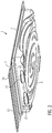
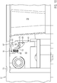
- Figure 1 shows a deep-drawn packaging 1, comprising a shell 3 and an upper film, which is not shown here for the sake of clarity.
- a circumferential, horizontal edge 7 is formed on an upper side 5 of the shell 3, on which a first sealing seam 9 forms the shell 3 the top film connects.
- a clamping section 13 is arranged on the edge 7 via a dividing line 11, which can be a pre-cut or a perforation.
- the one-piece top film is connected to the clamping section 13 via a second and third sealing seam 15, 17.
- the clamping section 13 has a centrally arranged contour 19.
- the sealed packaging 1 is separated and cut after the sealing process, so that the top film with the shell 3, in particular with the edge 7 and the clamping section 13, is congruent in its horizontal shape.
- Two rear extensions 23 are formed on a side surface 21.
- the shell 3 has further structures 25 in order to improve the stability and handling of the packaging 1.
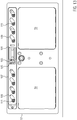
- Figure 2 shows the package 1 in an oblique view from below.
- the two rear extensions 23 can be seen, which essentially correspond to a quarter of an oval in cross section.
- the hind legs 23 each have a projection 27, behind which the clamping section 13 is clamped when the package 1 is closed again.
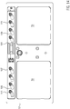
- Figure 3 shows the packaging 1 Figure 1 and 2 , in which the clamping section 13 was folded down on the dividing line 11 and pushed behind the projections 27.
- the clamping section 13 is expediently grasped and the upper film connected to it is at least partially removed from the shell 3, the first sealing seam 9 being released, but at least on the side of the edge 7 opposite the clamping section 13, the upper film and the shell 3 remains connected over part of the sealing seam 9.
- the clamping section 13 can be clamped behind the projections 27 and locked by the latter, the upper film stretching and exerting an outward pull on the clamping section 13.
- the clamping section 13 is clamped behind the projections 27 and the removal takes place with an elastic bend or twisting of the clamping section 13 and / or the rear sections 23 or other parts of the shell 3, with sufficient stability being present in the locked position shown to enable an independent movement To prevent the clamping section 13 from jumping out.
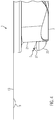
- Figure 4 shows a side sectional view of a package 1 with rear pull 23 and clamping section 13.
- the profile of the rear pull 23 and the projection 27 can be seen, the highest point of which is the apex S. From the apex S to the side surface 21, the profile of the Projection 27 here in a straight line, but it can also be concave, for example.
- the clamping section 13 has the contour 19 in the form of a downward bulge.
- Figure 5 shows the side sectional view of a package 1 according to Figure 4 , wherein the clamping portion 13 is pivoted down on the dividing line 11 and locked behind the projection 27.
- a width B of the clamping section 13 is larger than the direct distance A of the vertex S from the dividing line 11.
- the different sections are for clamping the clamping section 13 behind the projection 27 and for releasing the shell 3 is suitable to be elastically deformed to a small extent.
- the clamping section 13 can be bent slightly, an upward force can be exerted on the upper horizontal edge 7 and finally the side surface 21 can also twist to a limited extent.
- FIG. 6 shows a schematic view of a thermoformed packaging machine 41 with a forming station 43, a sealing station 45 and a cutting device 47.
- a lower film 49 is first rolled off a roll and, for example, clamped on both sides in transport chains, is fed to the forming station 43, where a tray 3 with a pull-back 23 is deep-drawn type described above.
- a cutting tool can be provided in the forming station 43 or separately.
- the dividing line 11 is expediently cut or perforated after the deep-drawing of the shell 3, since it should only be present in the lower foil 49, but not in the upper foil 53 spanning it.
- a product 51 is inserted into the shell 3 and the shell 3 sealed in the sealing station 45 with the top film 53.
- the deep drawing, filling and sealing can be carried out for each work step for one or also for several trays 3 which are arranged next to one another and / or one behind the other.
- the packaging 1 is then cut and separated by means of the cutting device 47, for example with round corner cuts of the upper edge 7 and the clamping section 13.
- a removal unit 55 transports the packaging 1 out of the thermoforming packaging machine 41.
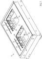
- Figure 7 shows a perspective view of a lower mold part 57 with two mold cavities 59 in a deep-drawing configuration.
- Each mold cavity 59 has two displaceable wall segments 61, which comprise an upper part 63 and a lower part 65.
- the wall segments 61 are arranged in a form-fitting and flush manner with the adjacent inner side surfaces 67 of the mold depression 59 and have a recess 69 for forming the rear pull-out 23.
- An upper support surface 71 is used to form the upper horizontal edge 7 and Clamping section 13, wherein the edge 7 is later cut to the desired dimensions by means of the cutting device 47.
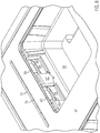
- Figure 8 shows an enlarged perspective view of a mold trough 59 in the removal configuration.
- the wall segments 61 are displaced outward, as a result of which the rear sections 23 of a deep-drawn shell 3 are released for vertical movement. Since a projection 27 is formed on the upper side of the rear extensions 23, the upper parts 63 of the wall segments 61 are rotated about the projections 27 in addition to their horizontal movement, for example by an angle of approximately 30 °.
- Figure 9 shows a side sectional view of a mold cavity 59 or the mold lower part 57 in a deep-drawing configuration accordingly Figure 7 ,
- the wall segment 61 and thus its upper part 63 and lower part 65 are flush with the other side surfaces 67 of the mold cavity 59 and form the desired profile for forming the rear section 23 and the projection 27 of the shell 3.
- one or more air channels 81 can be provided in the upper part 63 to form a negative pressure.
- the air duct 81 is expediently arranged at a most withdrawn position of the recesses 69, 79.
- the upper part 63 not only closes positively with the adjacent side surfaces 67 of the mold depression 59, but also abuts the lower part 65 of the wall segment 61 with a lateral section 83. As a result, a molding pressure can be derived from the stably mounted lower part 65.
- Figure 10 shows a side sectional view of a mold cavity 59 or the mold lower part 57 in the removal configuration accordingly Figure 8 .
- the wall segment 61 is displaced outwards, to the left in this illustration, in order to release the shell 3 for vertical removal.
- the wall segment 61 is therefore moved into a position in which the rear pull 23 does not collide with the wall segment 61, in particular the upper part 63, when the lower part 57 of the mold is lowered.
- the upper part 63 is rotatably supported about an axis of rotation 85 and is rotated when the wall segment 61 is moved upward around the projection 27 into the position shown.
- the axis of rotation 85 is mounted on the lower part 65. Due to the shape of an upper edge 87 of the upper part 63, this always remains below its uppermost vertical extent, which the upper part 63 also assumes during the deep-drawing configuration, during the rotation through the relevant angular range.
- the upper edge 87 is designed in the form of a circular arc concentric about the axis of rotation 85, this shape also being suitable for shaping the shell 3 at the same time.
- a reset mechanism 89 here in the form of a spiral spring, is connected to the upper part 63 via a lever section 91 and is mounted on the lower part 65, and can cause the upper part 63 to rotate into a corresponding end position by means of a tensile or compressive force.
- a nozzle bore 93 is formed in the lower mold part 57, which is closed, for example in the deep-drawing configuration of the lower mold part 57, by the wall segment 61 and is released in the removal configuration as shown in order to allow an air flow on and along the wall segment 61 and to cool it.
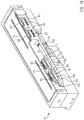
- Figure 11 shows a perspective view of four wall segments 61 with drive components in the positions for the deep-drawing configuration.
- the representation is comparable to an exploded drawing, the relative arrangement of the components being indicated by dashed lines.
- a linear drive 101 for example an electric motor or a pneumatic cylinder, comprises a rod, at the end of which a plate 103 is arranged, the drive 101 being configured to move the plate 103 back and forth along the direction of movement Z.
- the plate 103 engages with a clamp 105 of a slide 107 and causes the slide 107 to move accordingly.
- the slide 107 has one or more curved control grooves 109, in each of which a pin 111 of the wall segment 61 is slidably mounted.
- the wall segment 61 is mounted in guides of the lower mold part 57 such that the movement of the slide 107 along the direction of movement Z causes the wall segment 61 to move perpendicularly thereto.
- Wall segments 61 each with two pins 111 are shown here. However, it is also conceivable to provide only one pin 111, for example arranged in the center, per wall segment 61.
- Figure 12 shows a perspective view of four wall segments 61 with drive components in removal configuration. Compared to Figure 11 is the plate 103, and thus the slide 107, moved to the right by means of a rod 113. Since the wall segments 61 have no degree of freedom of movement in the direction Z due to their guidance in the lower mold part 57, they only perform a movement perpendicular thereto, caused by the control groove 109. At the same time, the rotational movement of the upper parts 63 of the wall segment 61 is caused.
- Figure 13 shows a horizontal sectional view of a lower mold part 57 in a deep-drawing configuration.
- the plate 103 is in a retracted position and the slide 107 in a position on the right in this illustration.
- the control groove 109 thus move the pin 111 and thus the wall segment 61 so that a shell 3 can be deep drawn.
- Figure 14 shows a horizontal sectional view of a mold lower part 57 in the removal configuration.
- the slide 107 is shifted to the left so that the pins 111 and thus the wall segments 61 are moved away from the mold cavity 59 in order to allow the lower part of the mold 57 to be lowered and thus the further transport of the shells 3 after the deep-drawing.
- Figure 15 shows a perspective view of an angled section of the lower mold part 57 in a deep-drawing configuration corresponding to FIG Figures 11 and 13 ,
- the side surface 67 of the mold cavity 59 is shown in order to show the flush termination of the wall segments 61 with precisely this side surface 67 in the deep-drawing configuration.
- the side face 67 has been left open to show the slide 107.
- Figure 16 shows a perspective view of an angled section of the mold lower part 57 in the removal configuration corresponding to FIG Figures 12 and 14 ,
- the wall segments 61 are moved away from the mold depression 59 and outwards by means of the control groove 109 and the pins 111 arranged therein due to the rightward displacement of the slide 107.
- the upper parts 63 are rotated.
- a lower film 49 is first fed to a molding station 43, clamped in it between a lower mold part 57 and an upper mold part when the forming station 43 is closed, and then deep-drawn into a mold 3 to form a shell 3 with the formation of suitable temperatures and pressure differences. Doing so by means of a suitable recess 69, which is formed in a displaceable wall segment 61, a rear pull 23 with a projection 27 is formed on a side surface 21.
- a dividing line 11 between an upper edge 7 and a clamping section 13, which is formed as an extension of the upper edge 7, is then cut or perforated in or subsequent to the forming station 43, the dividing line 11 being designed such that the clamping section 13 is initially in Connection to the edge 7 remains, but detaches from the edge 7 at a first kink at the dividing line 11.
- the wall segment 61 is displaced outward and away from the mold cavity 59.
- An upper part 63 of the wall segment 61 additionally executes a rotary movement so that it does not collide with a projection 27 of the rear section 23 during the horizontal displacement movement of the wall segment 61.
- the shell 3 is filled with a product 51 and sealed in a gas-tight manner in a sealing station 45 with an upper film 53.
- the upper film 53 extends both over the edge 7 of the shell 3 and over the clamping section 13 and there is a first sealing seam 9 on the edge 7 and a second sealing seam 15 on the clamping section 13 and optionally a third sealing seam 17 with the upper film 53 trained.
- the contour of the upper edge 7 and of the clamping section 13 is then cut in a cutting device 47, the corners preferably being given a round cut. If several trays 3 are formed and sealed next to or in succession per work step in the thermoforming packaging machine 41, the packages 1 are also separated by means of the cutting device 47. The individual packages 1 are removed by means of a removal unit 55.
- the mold trough 59 can also have a round or oval shape on the side in order to produce corresponding packagings 1, the wall segments 61 also being adapted accordingly.
- the displaceable wall segments 61 can also have knobs, pins or the like in order to form contours protruding into the pack.
Abstract
Verpackung (1), insbesondere Tiefziehfolienverpackung, mit einer Schale (3) zum Einlegen eines Produkts (51) und einem an einer Oberseite (5) der Schale (3) umlaufenden, im Wesentlichen horizontalen Rand (7), mit dem zumindest abschnittsweise ein Klemmabschnitt (13) mittels einer Trennlinie (11) lösbar verbunden ist. Die Verpackung (1) umfasst des Weiteren eine Oberfolie (53), welche sich wenigstens abschnittsweise über die Schale (3), den Rand (7) und den Klemmabschnitt (13) erstreckt und mit einer umlaufenden ersten Siegelnaht (9) mit dem Rand (7) lösbar verbunden ist und so die Schale (3) gasdicht verschließt, und die Oberfolie (53) mit einer zweiten Siegelnaht (15) mit dem Klemmabschnitt (13) verbunden ist. An einer Seitenfläche (21) der Schale (3) ist ein Hinterzug (23) angeordnet, der einen Vorsprung (27) aufweist, wobei der Vorsprung (27) dazu geeignet ist, den Klemmabschnitt (13) zu arretieren, wenn der Klemmabschnitt (13) an der Trennlinie (11) von dem Rand (7) gelöst ist und sich zumindest abschnittsweise zwischen dem Vorsprung (27) des Hinterzugs (23) und der Seitenfläche (21) der Schale (3) befindet. Desweiteren wird eine Tiefziehverpackungsmaschine (41) mit einem verschiebbaren Wandsegment (61) und ein Verfahren zum Betrieb der Tiefziehverpackungsmaschine (41) beschrieben.Packaging (1), in particular thermoformed film packaging, with a tray (3) for inserting a product (51) and an essentially horizontal edge (7) surrounding an upper side (5) of the tray (3), with a clamping section at least in sections (13) is detachably connected by means of a dividing line (11). The packaging (1) further comprises an upper film (53) which extends at least in sections over the shell (3), the edge (7) and the clamping section (13) and with a circumferential first sealing seam (9) with the edge ( 7) is detachably connected and thus seals the shell (3) in a gastight manner, and the top film (53) is connected to the clamping section (13) with a second sealing seam (15). On one side surface (21) of the shell (3) there is a rear pull (23) which has a projection (27), the projection (27) being suitable for locking the clamping section (13) when the clamping section (13 ) on the dividing line (11) from the edge (7) and is at least in sections between the projection (27) of the rear pull (23) and the side surface (21) of the shell (3). Furthermore, a deep-drawing packaging machine (41) with a displaceable wall segment (61) and a method for operating the deep-drawing packaging machine (41) are described.
Description
Die vorliegende Erfindung betrifft eine wiederverschließbare Verpackung sowie eine Tiefziehverpackungsmaschine zum Herstellen einer solchen Verpackung und ein Verfahren zum Betrieb der Tiefziehverpackungsmasch i ne.The present invention relates to a reclosable packaging and a thermoforming packaging machine for producing such packaging and a method for operating the thermoforming packaging machine.
Zunehmend Verwendung finden Verpackungen, die eine aus einer stabilen Unterfolie bzw. Hartfolie tiefgezogene Schale umfassen, welche mit einer Oberfolie verschlossen ist. Besonders für Lebensmittelprodukte sind diese Verpackungen nach dem ersten Öffnen wiederverschließbar, was beispielsweise durch eine ihre Wirkung zumindest teilweise beibehaltende Klebenaht erreicht wird. Eine solche Verpackung ist beispielsweise aus der
Die tiefgezogenen Schalen der Verpackungen sind üblicherweise in einer im Querschnitt betrachtet rechteckigen Form, in Form eines Parallelogramms oder in Trapezform, bei welcher sich der horizontale Querschnitt der Schale von oben nach unten verjüngt, ausgebildet. In allen diesen Fällen ist ein Entnehmen der Schale nach oben, bzw. schräg nach oben aus einer Formmulde nach dem Tiefziehen der Unterfolie problemlos möglich, wie beispielsweise in der
Es kann jedoch auch mitunter nötig sein, von diesen Standardformen abzuweichen und Schalen zu fertigen, welche an den Seitenflächen sich nach unten hin verbeiternde Abschnitte oder Ausbuchtungen, sogenannte Hinterzüge, oder auch Einstülpungen in Richtung des Schaleninneren aufweisen. Damit kann die Schale nach dem Tiefziehen nicht mehr ohne Weiteres aus der Formmulde entnommen werden, da diese Konturen der Schale mit den entsprechenden Teilen der Formmulde kollidieren. Abhilfe schafft hier das Wegschieben oder Wegklappen von Wandsegmenten der Formmulde, wie beispielsweise in der
Aufgabe der vorliegenden Erfindung ist es, eine Verpackung mit verbessertem Wiederverschließmechanismus und eine Tiefziehverpackungsmaschine zur Herstellung einer solchen Verpackung bereit zu stellen.The object of the present invention is to provide a packaging with an improved reclosing mechanism and a thermoforming packaging machine for producing such a packaging.
Die Aufgabe wird erfindungsgemäß gelöst durch eine Verpackung gemäß Anspruch 1 sowie eine Tiefziehverpackungsmaschine gemäß Anspruch 8 und ein Verfahren zum Betrieb einer Tiefziehverpackungsmaschine gemäß Anspruch 15. Vorteilhafte Weiterbildungen sind in den Unteransprüchen angegeben.The object is achieved according to the invention by a packaging according to claim 1 and a thermoforming packaging machine according to claim 8 and a method for operating a thermoforming packaging machine according to
Eine erfindungsgemäße Verpackung, insbesondere Tiefziehfolienverpackung, umfasst eine Schale zum Einlegen eines Produkts mit einem an einer Oberseite der Schale umlaufenden, im Wesentlichen horizontalen Rand, mit dem zumindest abschnittsweise ein Klemmabschnitt mittels einer Trennlinie lösbar verbunden ist. Die Trennlinie kann eine Schneidlinie oder Perforation sein und derart ausgeführt sein, sich zu öffnen und damit den Klemmabschnitt vom horizontalen Rand zu trennen, wenn der Klemmabschnitt um die Trennlinie aus der Horizontalen abgewinkelt bzw. geknickt wird. Die Verpackung umfasst des Weiteren eine Oberfolie, welche sich wenigstens abschnittsweise über die Schale, den Rand und den Klemmabschnitt erstreckt und mit einer umlaufenden ersten Siegelnaht mit dem Rand lösbar verbunden ist und so die Schale gasdicht verschließt. Zudem ist die Oberfolie mit einer zweiten Siegelnaht mit dem Klemmabschnitt verbunden. An einer Seitenfläche der Schale ist ein Hinterzug angeordnet, der einen Vorsprung aufweist, wobei der Vorsprung dazu geeignet ist, den Klemmabschnitt zu arretieren, wenn der Klemmabschnitt an der Trennlinie von dem Rand gelöst ist und sich zumindest abschnittsweise zwischen dem Vorsprung des Hinterzugs und der Seitenfläche der Schale befindet.A packaging according to the invention, in particular thermoformed film packaging, comprises a tray for inserting a product with a substantially horizontal edge running around an upper side of the tray, to which a clamping section is detachably connected at least in sections by means of a dividing line. The dividing line can be a cutting line or perforation and can be designed to open and thus separate the clamping section from the horizontal edge when the clamping section is angled or kinked around the dividing line from the horizontal. The packaging further comprises an upper film which extends at least in sections over the shell, the edge and the clamping section and is detachably connected to the edge with a circumferential first sealing seam and thus closes the shell in a gas-tight manner. In addition, the top film is connected to the clamping section with a second sealing seam. On one side surface of the shell there is a rear pull which has a projection, the projection being suitable for locking the clamping section when the clamping section is detached from the edge at the dividing line and at least in sections between the projection of the rear pull and the side surface the shell is located.
So kann die Verpackung geöffnet werden, indem die Oberfolie von der Schale abgezogen wird. Dabei bleibt der Klemmabschnitt, welcher durch eine Knickbewegung von dem horizontalen Rand der Schale getrennt wurde, mit der Oberfolie verbunden. Ebenso bleibt ein Abschnitt der Oberfolie, zweckmäßigerweise an einer dem Klemmabschnitt gegenüberliegenden Seite der Schale, mit dieser verbunden, indem die Oberfolie nicht vollständig abgezogen wird. Wird nur ein Teil des Produkts aus der Schale entnommen, so kann nun die Verpackung wieder verschlossen werden, indem die Oberfolie wieder auf die Schale aufgelegt wird und der weiterhin mit der Oberfolie verbundene Klemmabschnitt nach unten geschwenkt und zwischen die zum Klemmabschnitt benachbarte Seitenfläche und den Vorsprung des an dieser Seitenfläche ausgebildeten Hinterzugs geklemmt wird. Dabei spannt sich die Oberfolie und liegt im Wesentlichen plan auf dem oberen horizontalen Rand der Schale auf und verschließt diese damit. Die Verpackung kann weiterhin mehrmals geöffnet und wieder geschlossen werden, wobei das in der Verpackung verbleibende Produkt im Wesentlichen luftdicht gelagert wird.The packaging can be opened by pulling the top film off the tray. The clamping section, which was separated from the horizontal edge of the shell by a bending movement, remains connected to the upper film. Likewise, a section of the upper film, expediently on a side of the shell opposite the clamping section, remains connected to the latter by not completely pulling off the upper film. If only a part of the product is removed from the tray, the packaging can now be closed again by placing the top film back on the tray and pivoting the clamping section still connected to the top film down and between the side surface adjacent to the clamping section and the projection of the rear pull formed on this side surface is clamped. The top film tightens and lies essentially flat on the upper horizontal edge of the shell and closes it with it. The packaging can furthermore be opened and closed several times, the product remaining in the packaging being stored essentially airtight.
Zweckmäßig ist der Abstand eines Scheitels des Vorsprungs zu der Trennlinie geringer als eine Breite des Klemmabschnitts. Somit ist sichergestellt, dass sich der Klemmabschnitt nicht selbständig aus der Arretierung lösen kann. Zum Einklemmen des Klemmabschnitts und zum Herausnehmen aus der Arretierung hinter dem Vorsprung werden Abschnitte der Verpackungsschale mit einem gewissen Kraftaufwand elastisch gebogen, so zum Beispiel der obere Rand der Schale benachbart zum Klemmabschnitt oder die Seitenfläche, an welcher der Hinterzug ausgebildet ist.The distance between a vertex of the projection and the dividing line is expediently less than a width of the clamping section. This ensures that the clamping section cannot release itself from the locking mechanism. To clamp the clamping section and to take it out of the catch behind the projection, sections of the packaging tray are elastically bent with a certain amount of force, for example the upper edge of the tray adjacent to the clamping section or the side surface on which the rear pull is formed.
In einer üblichen Variante weist der Klemmabschnitt eine derart gestaltete Kontur auf, um eine ausreichende Festigkeit des Klemmabschnitts zu gewährleisten, so dass dieser arretiert bleibt, wenn eine Zugkraft von der Oberfolie auf diesen ausgeübt wird. Die Kontur, welche beispielsweise eine abschnittsweise oder durchgängig über die Länge des Klemmabschnitts ausgebildete Einkerbung sein kann, kann bereits beim Tiefziehen ausgebildet werden. Wie bekannt ist, weisen strukturierte Flächen eine höhere Biege- und Verwindungsfestigkeit als vollständig ebene Flächen auf. Dementsprechend wird ein ungewolltes Verbiegen des Klemmabschnitts und ein Lösen aus der Arretierung verhindert.In a conventional variant, the clamping section has a contour designed in this way in order to ensure sufficient strength of the clamping section so that it remains locked when a tensile force is exerted on the upper film. The contour, which can be, for example, a notch formed in sections or continuously over the length of the clamping section, can already be formed during deep drawing. As is known, structured surfaces have a higher flexural and torsional strength than completely flat surfaces. Accordingly, an unwanted bending of the clamping section and a release from the locking is prevented.
In einer vorteilhaften Variante weist der Klemmabschnitt eine dritte Siegelnaht auf. Somit ist der Klemmabschnitt mit insgesamt zwei Siegelnähten und damit besonders stabil mit der Oberfolie verbunden. Insbesondere wenn der Klemmabschnitt eine Kontur zur Verstärkung aufweist, wie im vorangegangenen Abschnitt beschrieben, kann die Kontur mittig angeordnet und die Oberfolie beidseitig der Kontur mit dem Klemmabschnitt verbunden sein.In an advantageous variant, the clamping section has a third sealing seam. The clamping section is thus connected to a total of two sealing seams and is therefore particularly stably connected to the upper film. In particular if the clamping section has a contour for reinforcement, as described in the previous section, the contour can be arranged in the center and the top film can be connected to the clamping section on both sides of the contour.
In einer weiteren Variante entspricht der Hinterzug im seitlichen Profil betrachtet im Wesentlichen einem Viertel eines Ovals. Der Hinterzug weist also, insbesondere an seinem äußeren Verlauf, keine harten Ecken oder Kanten auf, was einerseits die Haptik und Optik der Verpackung verbessert, besonders da damit auch ein Eindrücken oder Verformen solcher Ecken und Kanten nicht stattfindet, und andererseits auch die beim Arretieren des Klemmabschnitts auftretenden Kräfte vorteilhaft in die Seitenfläche der Schale abgeleitet werden.In a further variant, the rear profile, viewed in the lateral profile, essentially corresponds to a quarter of an oval. The backing therefore has no hard corners or edges, particularly on its outer shape, which improves the feel and appearance of the packaging, especially since it does not cause such corners and edges to be pressed in or deformed, and also when locking the Forces occurring in the clamping section can advantageously be derived into the side surface of the shell.
Bevorzugt ist die zweite und/oder dritte Siegelnaht nicht-lösbar ausgebildet. Die Siegelnähte, welche die Oberfolie mit dem Klemmabschnitt verbinden, können damit nicht versehentlich von dem Konsumenten aufgezogen werden.The second and / or third sealing seam is preferably non-detachable. The sealing seams that connect the top film to the clamping section cannot be accidentally pulled open by the consumer.
Vorzugsweise ist die erste Siegelnaht als wiederverschließbare Klebeverbindung ausgebildet. So kann nach dem erstmaligen Öffnen der Verpackung die Oberfolie zusätzlich wieder angedrückt werden, um die Verpackung besonders luftdicht zu verschließen. Zusammen mit der Niederhaltung der Folie durch das Einspannen des Klemmabschnitts hinter den Vorsprung des Hinterzugs wird ein besonders zuverlässiger luftdichter Verschluss der Verpackung erreicht.The first sealing seam is preferably designed as a reclosable adhesive connection. After opening the packaging for the first time, the top film can also be pressed on again to seal the packaging particularly airtight. Together with the holding down of the film by clamping the clamping section behind the projection of the pull-back, a particularly reliable airtight closure of the packaging is achieved.
Eine erfindungsgemäße Tiefziehverpackungsmaschine zum Herstellen einer Verpackung, insbesondere einer Verpackung entsprechend der vorangegangenen Beschreibung, umfasst eine Formstation zum Tiefziehen einer Unterfolie, wobei die Formstation wiederum ein Formwerkzeugunterteil mit einer Formmulde umfasst und die Formmulde ein Wandsegment aufweist, welches ausgebildet ist, eine Seitenfläche der Verpackung mit einem Hinterzug zu formen. Das Wandsegment umfasst ein Oberteil und ein Unterteil und ist von einer ersten Position, bei welcher sich die Formmulde in einer Tiefziehkonfiguration befindet, in eine zweite Position, bei welcher sich die Formmulde in einer Entnahmekonfiguration befindet, verschiebbar gelagert. Die Tiefziehkonfiguration ist zum Tiefziehen der Unterfolie geeignet, und die Entnahmekonfiguration ist zum Absenken des Formwerkzeugunterteils und damit zur Entnahme der Verpackung, insbesondere kollisionsfrei, geeignet. Dabei ist das Oberteil derart an dem Unterteil angelenkt, um mit diesem verschoben zu werden und dabei eine Drehbewegung relativ zum Unterteil auszuführen. In der Tiefziehkonfiguration ist das Wandsegment, inklusive Ober- und Unterteil, so angeordnet, dass die Formstation geschlossen werden kann, indem ein Formwerkzeugoberteil mit dem Formwerkzeugunterteil in Anlage gebracht wird. Die in die Formstation eingebrachte Unterfolie kann dann durch die Ausbildung einer Druckdifferenz zwischen ihrer Ober- und Unterseite und gegebenenfalls durch Erwärmen in die Formmulde tiefgezogen werden, d.h. sie passt sich den Flächen und Konturen der Formmulde an und es entsteht so eine entsprechend geformte Schale.A deep-drawing packaging machine according to the invention for producing a packaging, in particular a packaging according to the preceding description, comprises a molding station for deep-drawing a bottom film, the molding station in turn comprising a lower mold part with a mold cavity and the mold cavity having a wall segment which is designed with a side surface of the package to form a deceit. The wall segment comprises an upper part and a lower part and is displaceably mounted from a first position, in which the mold cavity is in a deep-drawing configuration, to a second position, in which the mold cavity is in a removal configuration. The deep-drawing configuration is suitable for deep-drawing the bottom film, and the removal configuration is suitable for lowering the lower part of the mold and thus for removing the packaging, in particular without collisions. In this case, the upper part is articulated on the lower part in order to be displaced therewith and thereby execute a rotary movement relative to the lower part. In the deep-drawing configuration, the wall segment, including the upper and lower part, is arranged so that the molding station can be closed by bringing an upper mold part into contact with the lower mold part. The bottom film introduced into the molding station can then be deep-drawn into the mold cavity by forming a pressure difference between its top and bottom and, if necessary, by heating. it adapts to the surfaces and contours of the mold cavity, creating a suitably shaped shell.
Zum Entnehmen der geformten Schale wird die Formstation geöffnet und beispielsweise das Formwerkzeugunterteil nach unten gefahren, um die Schale zum seitlichen Abtransport freizugeben. Für eine wie oben beschriebene Schale ist eine derartige Relativbewegung von Schale und Formmulde aber nicht ohne Weiteres möglich, da der an einer Seitenfläche geformte Hinterzug mit dem Wandsegment kollidieren würde. Dies wird durch ein seitliches Verschieben des Wandsegments nach außen von der Formmulde weg behoben. Da eine Verpackung der eingangs beschriebenen Art einen Hinterzug mit einem an diesem oben angeordneten Vorsprung aufweist, ist jedoch ein bloßes seitliches Verschieben ebenfalls nicht möglich, da der Vorsprung mit dem Wandsegment kollidieren würde. Dies wird wiederum gelöst, in dem das Wandsegment in ein Oberteil und ein Unterteil geteilt wird und beim Verschieben des Wandsegments das Oberteil eine zusätzliche Drehbewegung um den Vorsprung des Hinterzugs ausführt. Somit wird die tiefgezogene Schale freigegeben und kann in einem automatisierten Vorgang in einer vertikalen Bewegung aus der Formmulde entnommen werden.To remove the molded shell, the molding station is opened and, for example, the lower part of the mold is moved downwards in order to release the shell for lateral removal. For a shell as described above, however, such a relative movement of the shell and the mold trough is not readily possible, since the rear recess formed on one side surface would collide with the wall segment. This is remedied by moving the wall segment to the side away from the mold cavity. Since a package of the type described at the outset has a rear section with a projection arranged on it at the top, a mere lateral displacement is also not possible, since the projection would collide with the wall segment. This is in turn solved by dividing the wall segment into an upper part and a lower part and when the wall segment is moved, the upper part executes an additional rotary movement around the projection of the rear section. The deep-drawn shell is thus released and can be removed from the mold cavity in a vertical movement in an automated process.
In die Formstation kann des Weiteren ein Schneidwerkzeug integriert sein, um die Trennlinie zwischen Klemmabschnitt und oberen Rand der Schale als Anschnittlinie oder Perforation zu schneiden. Ein solches Schneidwerkzeug kann jedoch auch separat und zweckmäßig als stromabwärts nächste Station der Tiefziehverpackungsmaschine vorhanden sein. Üblicherweise schließt sich eine Station zum Einlegen der Produkte in die Schale, eine Siegelstation zum Verschließen der Schale mit einer Oberfolie sowie eine Schneidstation zum Schneiden und Vereinzeln der versiegelten Verpackungen an.A cutting tool can also be integrated in the forming station in order to cut the dividing line between the clamping section and the upper edge of the shell as a cut line or perforation. However, such a cutting tool can also be provided separately and expediently as the next station of the thermoforming packaging machine downstream. This is usually followed by a station for inserting the products into the tray, a sealing station for closing the tray with an upper film, and a cutting station for cutting and separating the sealed packages.
Typischerweise ist das Oberteil derart an dem Unterteil angelenkt, dass das Oberteil beim Ausführen der Drehbewegung während des Verschiebens des Wandsegments stets unterhalb seiner obersten vertikalen Erstreckung bleibt, die es in der Position aufweist, wenn die Formmulde in der Tiefziehkonfiguration ist. Bei bisherigen vergleichbaren Konstruktionen mit bewegbaren Wandsegmenten einer Formmulde, wie oben im Stand der Technik beschrieben, besteht die Problematik, dass die Bewegungen des Wandsegments durch andere Abschnitte der Formmulde oder die tiefgezogene Unterfolie behindert werden und beispielsweise ein Wandsegment nur mit gleichzeitiger Vertikalbewegung der tiefgezogenen Schale verschoben oder gedreht werden kann. Mit der vorliegenden Ausführungsform, welche weiter unten anhand der Abbildungen näher erläutert wird, stößt das Oberteil beim Ausführen der Drehbewegung nicht an einen oberen Rand der Schale. Es kann somit auch selbst als Auflagefläche zum Formen des oberen Schalenrandes dienen. Zudem kann das Verschieben des Wandsegments und Freigeben der Verpackungsschale als vom eigentlichen Entnehmen der Verpackungsschalen unabhängiger Vorgang im Fertigungsprozess geplant werden.Typically, the top part is hinged to the bottom part such that the top part, when performing the rotational movement while moving the wall segment, always remains below its uppermost vertical extension, which it has in the position when the mold cavity is in the deep-drawing configuration. In previous comparable constructions with movable wall segments of a mold trough, as described above in the prior art, there is the problem that the movements of the wall segment are hindered by other sections of the mold trough or the deep-drawn bottom film and, for example, a wall segment is only moved with simultaneous vertical movement of the deep-drawn shell or can be rotated. With the present embodiment, which is explained in more detail below with reference to the figures, the upper part does not abut an upper edge of the shell when the rotary movement is carried out. It can therefore also serve itself as a contact surface for shaping the upper edge of the shell. In addition, moving the wall segment and releasing the packaging tray can be planned as a process in the manufacturing process that is independent of the actual removal of the packaging trays.
In einer gängigen Variante ist das Oberteil an einer an dem Unterteil angeordneten Drehachse angelenkt. Dies ist eine besonders einfache und zweckmäßige Konstruktion, da das Oberteil keine weiteren Führungen oder Verbindungen an oder mit dem Formwerkzeugunterteil benötigt. Die Kraftübertragung zur Veranlassung der Drehbewegung erfolgt dementsprechend nur über das Unterteil des verschiebbaren Wandsegments.In a common variant, the upper part is articulated on an axis of rotation arranged on the lower part. This is a particularly simple and expedient construction, since the upper part does not require any further guides or connections on or with the lower part of the mold. Accordingly, the power transmission for initiating the rotary movement takes place only via the lower part of the displaceable wall segment.
Üblicherweise liegt das Oberteil in der Tiefziehkonfiguration der Formmulde an dem Unterteil formschlüssig an. Dies bedeutet einerseits, dass die Ränder des Oberteils so mit dem Unterteil und den anliegenden Abschnitten der Formmulde abschließen, dass keinerlei unerwünschte Vorsprünge oder Vertiefungen während des Tiefziehens vorhanden sind, um eine einwandfreie Schalenform herzustellen. Zusätzlich kann das Oberteil jedoch so an dem Unterteil anliegen, dass ein beim Tiefziehen auftretender Formdruck in das Unterteil abgeleitet wird und somit ein ungewolltes Drehen um die Drehachse verhindert wird. Dazu ist eine Auflagefläche des Oberteils an einem zur Drehachse entfernten Ende ausgebildet.The upper part usually lies in a form-fitting manner on the lower part in the deep-drawing configuration of the mold cavity. On the one hand, this means that the edges of the upper part are flush with the lower part and the adjoining sections of the mold cavity in such a way that no undesired projections or depressions are present during deep-drawing in order to produce a perfect shell shape. In addition, however, the upper part can rest against the lower part in such a way that a molding pressure occurring during deep drawing is diverted into the lower part and thus an unwanted one Rotation around the axis of rotation is prevented. For this purpose, a contact surface of the upper part is formed at an end remote from the axis of rotation.
In einer weiteren gängigen Variante ist das Oberteil mit einem Rückstellmechanismus, insbesondere einer Feder, an dem Unterteil angelenkt, um beim Verschieben des Wandsegments automatisch in eine Endlage zurückzukehren. Eine solche Konstruktion ist besonders einfach und damit günstig herzustellen.In a further common variant, the upper part is articulated on the lower part with a resetting mechanism, in particular a spring, in order to automatically return to an end position when the wall segment is moved. Such a construction is particularly simple and therefore inexpensive to manufacture.
Vorzugsweise weist das Formwerkzeugunterteil Düsenbohrungen auf, um zur Kühlung des Wandsegments Luft auf dieses zu blasen, wobei die Düsenbohrungen verschlossen sind, wenn sich die Formmulde in der Tiefziehkonfiguration befindet, und aktiv sind, wenn sich die Formmulde in der Entnahmekonfiguration befindet. Dabei kann das Öffnen und Schließen der Düsenbohrungen durch einen eigenständigen, mit der Bewegung des Wandsegments jedoch synchronisierten Mechanismus erfolgen. Alternativ kann auch ein Abschnitt des Wandsegments selbst je nach Position die Düsenbohrungen luftdicht abdecken oder freigeben. Somit kann auch im letzteren Fall eine Kühlung des Wandsegments im geöffneten Zustand stattfinden, wenn ein Abströmen der Luft möglich ist.The mold lower part preferably has nozzle bores in order to blow air onto the wall segment for cooling purposes, the nozzle bores being closed when the mold cavity is in the deep-drawing configuration and are active when the mold cavity is in the removal configuration. The opening and closing of the nozzle bores can be carried out by an independent mechanism that is synchronized with the movement of the wall segment. Alternatively, depending on the position, a section of the wall segment itself can cover or uncover the nozzle bores in an airtight manner. Thus, in the latter case, cooling of the wall segment can take place in the open state if the air can flow out.
In einer weiteren vorteilhaften Variante weist die Tiefziehverpackungsmaschine einen linearen Antrieb auf, welcher mit einem Schieber in Eingriff ist, um diesen zu bewegen, und wobei der Schieber eine kurvenförmige Steuernut aufweist. Das verschiebbare Wandsegment umfasst dabei einen Zapfen, der mit der Steuernut in Eingriff ist, so dass das Wandsegment beim Betätigen des Antriebs linear verschoben wird. Wie weiter unten anhand der Abbildungen näher erläutert, ist dies eine besonders platzsparende Anordnung, welche eine Linearbewegung in eine dazu senkrechte Linearbewegung übersetzt. Zudem kann der Schieber mit mehreren Steuernuten ausgebildet werden, um so mehrere nebeneinander liegende Wandsegmente gleichzeitig zu bewegen. Außerdem ist der Schieber so gelagert und die Steuernut so geformt, dass das Wandsegment nicht durch einen Formdruck aufgedrückt werden kann, da nur eine seitliche Bewegung des Schiebers, parallel zur Formmulde, die Verschiebung des Wandsegments verursachen kann.In a further advantageous variant, the thermoforming packaging machine has a linear drive which engages with a slide in order to move it, and the slide has a curved control groove. The displaceable wall segment comprises a pin which engages with the control groove, so that the wall segment is displaced linearly when the drive is actuated. As explained in more detail below with the aid of the figures, this is a particularly space-saving arrangement which translates a linear movement into a linear movement perpendicular thereto. In addition, the slide can be designed with a plurality of control grooves in order to move a plurality of wall segments lying next to one another at the same time. In addition, the slide is mounted and the control groove is shaped so that the wall segment cannot be pressed open by a molding pressure, since only a lateral movement of the slide, parallel to the mold cavity, can cause the wall segment to shift.
Im Folgenden werden Ausführungsbeispiele der Erfindung anhand der Figuren näher beschrieben. Dabei zeigen
- Figur 1:
- eine perspektivische Draufsicht auf eine Verpackung,
- Figur 2:
- eine perspektivische Ansicht von schräg unten auf eine Verpackung,
- Figur 3:
- eine perspektivische Ansicht von schräg unten auf eine Verpackung mit umgeklapptem Klemmabschnitt,
- Figur 4:
- eine seitliche Schnittansicht einer Verpackung im Bereich eines Hinterzugs,
- Figur 5:
- eine seitliche Schnittansicht einer Verpackung im Bereich eines Hinterzugs mit umgeklapptem Klemmabschnitt,
- Figur 6:
- eine schematische Ansicht einer Tiefziehverpackungsmaschine,
- Figur 7:
- eine perspektivische Ansicht eines Formwerkzeugunterteils mit zwei Formmulden in Tiefziehkonfiguration,
- Figur 8:
- eine perspektivische Ansicht einer Formmulde in Entnahmekonfiguration,
- Figur 9:
- eine seitliche Schnittansicht einer Formmulde in Tiefziehkonfiguration,
- Figur 10:
- eine seitliche Schnittansicht einer Formmulde in Entnahmekonfiguration,
- Figur 11:
- eine perspektivische Ansicht von vier Wandsegmenten mit Antriebskomponenten in Tiefziehkonfiguration,
- Figur 12:
- eine perspektivische Ansicht von vier Wandsegmenten mit Antriebskomponenten in Entnahmekonfiguration,
- Figur 13:
- eine Schnittansicht eines Formwerkzeugunterteils in Tiefziehkonfiguration,
- Figur 14:
- eine Schnittansicht eines Formwerkzeugunterteils in Entnahmekonfiguration,
- Figur 15:
- eine perspektivische Ansicht eines gewinkelten Schnitts des Formwerkzeugunterteils in Tiefziehkonfiguration,
- Figur 16:
- eine perspektivische Ansicht eines gewinkelten Schnitts des Formwerkzeugunterteils in Entnahmekonfiguration.
- Figure 1:
- a top perspective view of a package,
- Figure 2:
- a perspective view obliquely from below on a package,
- Figure 3:
- a perspective view obliquely from below of a package with the clamping section folded down,
- Figure 4:
- a sectional side view of a package in the area of a rear pull,
- Figure 5:
- 2 shows a side sectional view of a packaging in the area of a rear pull-out with the clamping section folded down,
- Figure 6:
- 1 shows a schematic view of a thermoforming packaging machine,
- Figure 7:
- 1 shows a perspective view of a lower mold part with two mold cavities in a deep-drawing configuration,
- Figure 8:
- a perspective view of a mold trough in the removal configuration,
- Figure 9:
- a sectional side view of a mold cavity in a deep-drawing configuration,
- Figure 10:
- a sectional side view of a mold trough in the removal configuration,
- Figure 11:
- a perspective view of four wall segments with drive components in a deep-drawing configuration,
- Figure 12:
- a perspective view of four wall segments with drive components in the removal configuration,
- Figure 13:
- 2 shows a sectional view of a lower mold part in a deep-drawing configuration,
- Figure 14:
- 2 shows a sectional view of a lower mold part in the removal configuration,
- Figure 15:
- 1 shows a perspective view of an angled section of the lower part of the mold in a deep-drawing configuration,
- Figure 16:
- a perspective view of an angled section of the lower mold part in the removal configuration.
Einander entsprechende Komponenten sind in den Figuren jeweils mit gleichen Bezugszeichen versehen.Corresponding components are provided with the same reference symbols in the figures.
Im Folgenden wird die Funktionsweise einer erfindungsgemäßen Tiefziehverpackungsmaschine 41 zum Herstellen einer Verpackung 1 erläutert.The mode of operation of a deep-drawing
Wie bereits in
Nach dem Absenken des Formwerkzeugunterteils 57 und einem Weitertransport wird die Schale 3 mit einem Produkt 51 befüllt und in einer Siegelstation 45 mit einer Oberfolie 53 gasdicht versiegelt. Dabei erstreckt sich die Oberfolie 53 sowohl bis über den Rand 7 der Schale 3 als auch über den Klemmabschnitt 13 und es wird auf dem Rand 7 eine erste Siegelnaht 9 und auf dem Klemmabschnitt 13 eine zweite Siegelnaht 15 und optional eine dritte Siegelnaht 17 mit der Oberfolie 53 ausgebildet. Anschließend wird in einer Schneideeinrichtung 47 die Kontur des oberen Rands 7 sowie des Klemmabschnitts 13 geschnitten, wobei vorzugsweise die Ecken einen Rundschnitt erhalten. Werden in der Tiefziehverpackungsmaschine 41 mehrere Schalen 3 neben- oder hintereinander pro Arbeitsschritt geformt und versiegelt, so werden die Verpackungen 1 mittels der Schneideeinrichtung 47 auch vereinzelt. Mittels einer Abfördereinheit 55 werden die einzelnen Verpackungen 1 abtransportiert.After lowering the
Ausgehend von den oben dargestellten Ausführungsformen einer Verpackung 1, einer Tiefziehverpackungsmaschine 41 und eines Verfahrens zum Betrieb einer solchen Tiefziehverpackungsmaschine 41 sind vielerlei Variationen derselben denkbar. So kann die Formmulde 59 seitlich auch rund oder oval geformt sein um entsprechende Verpackungen 1 herzustellen, wobei auch die Wandsegmente 61 entsprechend angepasst sind. Die verschiebbaren Wandsegmente 61 können anstatt einer Ausnehmung 69 für einen Hinterzug 23 auch Noppen, Zapfen oder Ähnliches aufweisen, um in die Packung hineinragende Konturen zu formen. Anstatt einen Vorsprung 27 je Hinterzug 23 vorzusehen, ist es auch denkbar, einen breiteren Hinterzug 23 mit zwei oder mehreren Vorsprüngen 27 auszubilden.Starting from the above-described embodiments of a packaging 1, a deep-drawing
Claims (15)
Applications Claiming Priority (1)
| Application Number | Priority Date | Filing Date | Title |
|---|---|---|---|
| DE102018212836.7A DE102018212836A1 (en) | 2018-08-01 | 2018-08-01 | Resealable packaging, thermoforming packaging machine and process |
Publications (2)
| Publication Number | Publication Date |
|---|---|
| EP3604166A2 true EP3604166A2 (en) | 2020-02-05 |
| EP3604166A3 EP3604166A3 (en) | 2020-05-20 |
Family
ID=67514315
Family Applications (1)
| Application Number | Title | Priority Date | Filing Date |
|---|---|---|---|
| EP19188799.1A Withdrawn EP3604166A3 (en) | 2018-08-01 | 2019-07-29 | Reclosable package and deep draw packaging machine and method |
Country Status (3)
| Country | Link |
|---|---|
| US (1) | US11485561B2 (en) |
| EP (1) | EP3604166A3 (en) |
| DE (1) | DE102018212836A1 (en) |
Families Citing this family (2)
| Publication number | Priority date | Publication date | Assignee | Title |
|---|---|---|---|---|
| USD871208S1 (en) * | 2017-11-20 | 2019-12-31 | Frank Brunckhorst Co., L.L.C. | Container |
| US11077603B1 (en) * | 2020-03-23 | 2021-08-03 | Jay Baker | Method of producing a packaging container with a closure and release mechanism and retention elements |
Citations (3)
| Publication number | Priority date | Publication date | Assignee | Title |
|---|---|---|---|---|
| US5014500A (en) | 1989-06-16 | 1991-05-14 | Mecaplastic | Device and installation for forming and closing trays |
| EP2570351A1 (en) | 2011-09-16 | 2013-03-20 | Multivac Sepp Haggenmüller GmbH & Co. KG | Deep draw packaging machine for producing standing packaging with formed undercut |
| DE102015205221A1 (en) | 2015-03-23 | 2016-09-29 | Multivac Sepp Haggenmüller Se & Co. Kg | Thermoforming packaging machine, process and packaging |
Family Cites Families (15)
| Publication number | Priority date | Publication date | Assignee | Title |
|---|---|---|---|---|
| US3371848A (en) * | 1966-10-24 | 1968-03-05 | Anderson Bros Mfg Co | Reclosable package |
| US3398876A (en) * | 1967-02-06 | 1968-08-27 | Anderson Bros Mfg Co | Reclosable package |
| US3398877A (en) * | 1967-04-10 | 1968-08-27 | Anderson Bros Mfg Co | Reclosable package |
| US3495759A (en) * | 1968-04-24 | 1970-02-17 | Anderson Bros Mfg Co | Reclosable package |
| DE2323425B2 (en) * | 1973-05-09 | 1975-12-11 | Multivac Sepp Haggenmueller Kg, 8941 Wolfertschwenden | Forming tool with an element for forming a projection for deforming plastic films |
| FR2318790A1 (en) * | 1975-07-24 | 1977-02-18 | Bourbon Claude | Presentation pack moulded from single plastics sheet - has snap action edge to lock article into tray portion |
| US4495135A (en) * | 1982-08-09 | 1985-01-22 | Baxter Travenol Laboratories, Inc. | Method for forming container having re-entrant flange |
| CH677473A5 (en) * | 1988-12-02 | 1991-05-31 | Alusuisse | Container with resealable cover - has edge with weakened zones forming cone parting surface widening towards top |
| FR2880834B1 (en) * | 2005-01-19 | 2009-03-27 | Erca Formseal Sa | "DEVICE AND METHOD FOR THERMOFORMING OBJECTS HAVING A BASIC FLANGE, AND OBJECTS THUS OBTAINED |
| DE202006000955U1 (en) * | 2006-01-23 | 2006-05-18 | Striebel, Christhard | Foil packing for medicines in tablet form, comprises wall of the lamella like folded tablet single depots, a ring-shaped termination with narrowed opening toward depot exit, enclosed medicine tablet and depot dome for applying pressure |
| US8127573B2 (en) * | 2006-04-04 | 2012-03-06 | Emhart Glass S.A. | Mold cooling system for I.S. machine |
| FR3002922B1 (en) * | 2013-03-06 | 2015-10-30 | Cgl Pack Service | RETRACTABLE TRUNK TRAY |
| WO2016057046A1 (en) * | 2014-10-10 | 2016-04-14 | Bemis Company, Inc. | Snap close peel reseal package |
| JP6528987B2 (en) * | 2015-03-23 | 2019-06-12 | 大日本印刷株式会社 | Container with lid |
| DE102015217886A1 (en) * | 2015-09-17 | 2017-03-23 | Thyssenkrupp Ag | Sliding element for moving a cam segment |
-
2018
- 2018-08-01 DE DE102018212836.7A patent/DE102018212836A1/en not_active Withdrawn
-
2019
- 2019-07-29 EP EP19188799.1A patent/EP3604166A3/en not_active Withdrawn
- 2019-08-01 US US16/529,212 patent/US11485561B2/en active Active
Patent Citations (3)
| Publication number | Priority date | Publication date | Assignee | Title |
|---|---|---|---|---|
| US5014500A (en) | 1989-06-16 | 1991-05-14 | Mecaplastic | Device and installation for forming and closing trays |
| EP2570351A1 (en) | 2011-09-16 | 2013-03-20 | Multivac Sepp Haggenmüller GmbH & Co. KG | Deep draw packaging machine for producing standing packaging with formed undercut |
| DE102015205221A1 (en) | 2015-03-23 | 2016-09-29 | Multivac Sepp Haggenmüller Se & Co. Kg | Thermoforming packaging machine, process and packaging |
Also Published As
| Publication number | Publication date |
|---|---|
| US20200039716A1 (en) | 2020-02-06 |
| DE102018212836A1 (en) | 2020-02-06 |
| EP3604166A3 (en) | 2020-05-20 |
| US11485561B2 (en) | 2022-11-01 |
Similar Documents
| Publication | Publication Date | Title |
|---|---|---|
| DE60005611T2 (en) | Process for attaching a slide to a resealable packaging made of flexible material | |
| EP2029446B1 (en) | Flip-top packet for cigarettes | |
| DE2026964A1 (en) | Closure container and method and device for producing the same | |
| EP0808676A1 (en) | Method for producing an easy-open can lid and easy-open can lid | |
| AT398744B (en) | DEVICE FOR PRODUCING A CONTAINER, PREFERABLY A FILLED CONTAINER, FROM A FLAT CUT | |
| DE1461996A1 (en) | Packing machine | |
| DE102008051026A1 (en) | Means of transport and packaging machine for film width adjustment | |
| EP3604166A2 (en) | Reclosable package and deep draw packaging machine and method | |
| DE10105699A1 (en) | Method and device for producing a diffusion-tight plastic container | |
| DE2163759C3 (en) | Method and device for forming a circumferential bead on the edge of an open-topped container | |
| DE4122692B4 (en) | Device for wrapping cuboid objects | |
| EP0708025B1 (en) | Vertical bag forming, filling and sealing machine | |
| DE102017202839B4 (en) | Method and tool for producing a plastic container, in particular a fuel tank, by internal pressure molding | |
| EP2804706B1 (en) | Method for producing a can with a ring pull top, and can with a ring pull top | |
| EP2284082B1 (en) | Method for packaging products | |
| EP0453715A2 (en) | Apparatus for deep-drawing of an open shell | |
| DE102015016079B4 (en) | Method and device for folding a blank of wrapping material for the production of an insert for a rigid tobacco product packaging | |
| WO2004005148A1 (en) | Cover for cardboard composite beverage packages, tools and methods for producing such a cover, and cardboard composite beverage packages provided therewith | |
| DE102005029492B4 (en) | Apparatus for producing a tubular bag packaging | |
| DE102011004297B3 (en) | Shaping shoulder for tubular bag packaging machine, has incoming packaging material web that faces mold elements and translationally moves between operating position and opening position | |
| DE102016119818B3 (en) | Multi-part packaging | |
| EP0917948A1 (en) | Apparatus for making reclosable bags | |
| DE1461996C (en) | Packaging machine for vacuum packaging | |
| WO2021245052A1 (en) | Apparatus and method for assembling containers with a function rim from flat blanks | |
| DE1586460C (en) | Packaging as well as process and equipment for their manufacture |
Legal Events
| Date | Code | Title | Description |
|---|---|---|---|
| PUAI | Public reference made under article 153(3) epc to a published international application that has entered the european phase |
Free format text: ORIGINAL CODE: 0009012 |
|
| STAA | Information on the status of an ep patent application or granted ep patent |
Free format text: STATUS: THE APPLICATION HAS BEEN PUBLISHED |
|
| AK | Designated contracting states |
Kind code of ref document: A2 Designated state(s): AL AT BE BG CH CY CZ DE DK EE ES FI FR GB GR HR HU IE IS IT LI LT LU LV MC MK MT NL NO PL PT RO RS SE SI SK SM TR |
|
| AX | Request for extension of the european patent |
Extension state: BA ME |
|
| PUAL | Search report despatched |
Free format text: ORIGINAL CODE: 0009013 |
|
| AK | Designated contracting states |
Kind code of ref document: A3 Designated state(s): AL AT BE BG CH CY CZ DE DK EE ES FI FR GB GR HR HU IE IS IT LI LT LU LV MC MK MT NL NO PL PT RO RS SE SI SK SM TR |
|
| AX | Request for extension of the european patent |
Extension state: BA ME |
|
| RIC1 | Information provided on ipc code assigned before grant |
Ipc: B29C 51/34 20060101ALI20200415BHEP Ipc: B65D 77/20 20060101AFI20200415BHEP Ipc: B29L 31/00 20060101ALI20200415BHEP Ipc: B65B 47/10 20060101ALN20200415BHEP |
|
| STAA | Information on the status of an ep patent application or granted ep patent |
Free format text: STATUS: REQUEST FOR EXAMINATION WAS MADE |
|
| 17P | Request for examination filed |
Effective date: 20201117 |
|
| RBV | Designated contracting states (corrected) |
Designated state(s): AL AT BE BG CH CY CZ DE DK EE ES FI FR GB GR HR HU IE IS IT LI LT LU LV MC MK MT NL NO PL PT RO RS SE SI SK SM TR |
|
| STAA | Information on the status of an ep patent application or granted ep patent |
Free format text: STATUS: EXAMINATION IS IN PROGRESS |
|
| 17Q | First examination report despatched |
Effective date: 20220621 |
|
| GRAP | Despatch of communication of intention to grant a patent |
Free format text: ORIGINAL CODE: EPIDOSNIGR1 |
|
| STAA | Information on the status of an ep patent application or granted ep patent |
Free format text: STATUS: GRANT OF PATENT IS INTENDED |
|
| RIC1 | Information provided on ipc code assigned before grant |
Ipc: B65B 47/10 20060101ALN20230424BHEP Ipc: B65B 9/04 20060101ALI20230424BHEP Ipc: B29L 31/00 20060101ALI20230424BHEP Ipc: B29C 51/34 20060101ALI20230424BHEP Ipc: B65D 77/20 20060101AFI20230424BHEP |
|
| INTG | Intention to grant announced |
Effective date: 20230524 |
|
| P01 | Opt-out of the competence of the unified patent court (upc) registered |
Effective date: 20230801 |
|
| STAA | Information on the status of an ep patent application or granted ep patent |
Free format text: STATUS: THE APPLICATION IS DEEMED TO BE WITHDRAWN |
|
| 18D | Application deemed to be withdrawn |
Effective date: 20231005 |