EP3604053B1 - Kopplungsstruktur eines wischerarms - Google Patents
Kopplungsstruktur eines wischerarms Download PDFInfo
- Publication number
- EP3604053B1 EP3604053B1 EP19186318.2A EP19186318A EP3604053B1 EP 3604053 B1 EP3604053 B1 EP 3604053B1 EP 19186318 A EP19186318 A EP 19186318A EP 3604053 B1 EP3604053 B1 EP 3604053B1
- Authority
- EP
- European Patent Office
- Prior art keywords
- arm
- adaptor
- wiper
- shank
- coupling
- Prior art date
- Legal status (The legal status is an assumption and is not a legal conclusion. Google has not performed a legal analysis and makes no representation as to the accuracy of the status listed.)
- Active
Links
Images








Classifications
-
- B—PERFORMING OPERATIONS; TRANSPORTING
- B60—VEHICLES IN GENERAL
- B60S—SERVICING, CLEANING, REPAIRING, SUPPORTING, LIFTING, OR MANOEUVRING OF VEHICLES, NOT OTHERWISE PROVIDED FOR
- B60S1/00—Cleaning of vehicles
- B60S1/02—Cleaning windscreens, windows or optical devices
- B60S1/04—Wipers or the like, e.g. scrapers
- B60S1/32—Wipers or the like, e.g. scrapers characterised by constructional features of wiper blade arms or blades
- B60S1/40—Connections between blades and arms
-
- B—PERFORMING OPERATIONS; TRANSPORTING
- B60—VEHICLES IN GENERAL
- B60S—SERVICING, CLEANING, REPAIRING, SUPPORTING, LIFTING, OR MANOEUVRING OF VEHICLES, NOT OTHERWISE PROVIDED FOR
- B60S1/00—Cleaning of vehicles
- B60S1/02—Cleaning windscreens, windows or optical devices
- B60S1/04—Wipers or the like, e.g. scrapers
- B60S1/32—Wipers or the like, e.g. scrapers characterised by constructional features of wiper blade arms or blades
- B60S1/40—Connections between blades and arms
- B60S1/4038—Connections between blades and arms for arms provided with a channel-shaped end
- B60S1/4064—Connections between blades and arms for arms provided with a channel-shaped end the channel-shaped end being provided with protrusions on, or holes in, the side walls to create a pivot
-
- B—PERFORMING OPERATIONS; TRANSPORTING
- B60—VEHICLES IN GENERAL
- B60S—SERVICING, CLEANING, REPAIRING, SUPPORTING, LIFTING, OR MANOEUVRING OF VEHICLES, NOT OTHERWISE PROVIDED FOR
- B60S1/00—Cleaning of vehicles
- B60S1/02—Cleaning windscreens, windows or optical devices
- B60S1/04—Wipers or the like, e.g. scrapers
- B60S1/32—Wipers or the like, e.g. scrapers characterised by constructional features of wiper blade arms or blades
- B60S1/34—Wiper arms; Mountings therefor
- B60S1/3425—Constructional aspects of the arm
- B60S1/3445—Joints between elements
- B60S1/3447—Joints between elements the elements being an arm piece and a link piece
-
- B—PERFORMING OPERATIONS; TRANSPORTING
- B60—VEHICLES IN GENERAL
- B60S—SERVICING, CLEANING, REPAIRING, SUPPORTING, LIFTING, OR MANOEUVRING OF VEHICLES, NOT OTHERWISE PROVIDED FOR
- B60S1/00—Cleaning of vehicles
- B60S1/02—Cleaning windscreens, windows or optical devices
- B60S1/04—Wipers or the like, e.g. scrapers
- B60S1/32—Wipers or the like, e.g. scrapers characterised by constructional features of wiper blade arms or blades
- B60S1/34—Wiper arms; Mountings therefor
- B60S1/3479—Means to cover the wiper parts
- B60S1/3484—Means to cover the wiper parts integral with arm or link piece
-
- B—PERFORMING OPERATIONS; TRANSPORTING
- B60—VEHICLES IN GENERAL
- B60S—SERVICING, CLEANING, REPAIRING, SUPPORTING, LIFTING, OR MANOEUVRING OF VEHICLES, NOT OTHERWISE PROVIDED FOR
- B60S1/00—Cleaning of vehicles
- B60S1/02—Cleaning windscreens, windows or optical devices
- B60S1/04—Wipers or the like, e.g. scrapers
- B60S1/32—Wipers or the like, e.g. scrapers characterised by constructional features of wiper blade arms or blades
- B60S1/40—Connections between blades and arms
- B60S1/4038—Connections between blades and arms for arms provided with a channel-shaped end
-
- B—PERFORMING OPERATIONS; TRANSPORTING
- B60—VEHICLES IN GENERAL
- B60S—SERVICING, CLEANING, REPAIRING, SUPPORTING, LIFTING, OR MANOEUVRING OF VEHICLES, NOT OTHERWISE PROVIDED FOR
- B60S1/00—Cleaning of vehicles
- B60S1/02—Cleaning windscreens, windows or optical devices
- B60S1/04—Wipers or the like, e.g. scrapers
- B60S1/32—Wipers or the like, e.g. scrapers characterised by constructional features of wiper blade arms or blades
- B60S1/38—Wiper blades
- B60S1/3848—Flat-type wiper blade, i.e. without harness
- B60S1/3849—Connectors therefor; Connection to wiper arm; Attached to blade
- B60S1/3865—Connectors having an integral pivot pin for connection with the wiper arm
- B60S1/3868—Connectors having an integral pivot pin for connection with the wiper arm pin formed on the exterior of side walls
Definitions
- the disclosure relates to a blade holding member holding a wiper blade and a coupling structure of a wiper arm.
- a wiper apparatus is installed in a vehicle such as an automobile.
- a wiper apparatus includes a wiper motor that serves as a driving source, a wiper arm that oscillates when the wiper motor is driven, and a wiper blade that is mounted on a distal end side of the wiper arm.
- the wiper blade is held by a blade holding member, and the blade holding member is coupled to the wiper arm.
- the wiper blade performs reciprocating wiping operations on a wiping surface of a window glass of an automobile or the like.
- Patent Document 1 Japanese Laid-Open Publication No. 2015-214181 discloses a coupling structure of a wiper arm and a wiper blade.
- the foregoing Patent Document 1 discloses that a cylindrical portion forming a coupling shaft can be put in a locked posture or an attachment/detachment posture by causing a lever member, which oscillates with respect to a holding member holding a blade rubber, to oscillate. It also discloses that design of the wiper blade can be improved when the cylindrical portion is in the locked posture, and attachment/detachment work can be easily performed with less effort when the cylindrical portion is in the attachment/detachment posture.
- FR 3 022 201 A1 discloses a wiper arm for a motor vehicle rear window wiper system, comprising a lower arm extending longitudinally between a first end and a second end, the first end being arranged to be secured to one end of a connecting piece rotatably connected to a drive shaft of the blade arm, this end of the connecting piece being off-axis with respect to the drive shaft, and a upper arm extending between a third end and a fourth end, comprising a blade hook, remote from the third end, and adapted to be attached to a rear window wiper blade, wherein the third end and the second end are arranged so that the upper arm can be attached by the third end to the second end of the lower arm.
- the coupling structure of the wiper arm and the wiper blade disclosed in the foregoing Patent Document 1 is a structure in which the wiper arm and the wiper blade are coupled to each other at one place when they are assembled.
- the disclosure provides a coupling structure of a wiper arm which is applicable to wiper blades of a plurality of types having different lengths.
- a coupling structure of a wiper arm coupled to a blade holding member in an attachable/detachable manner on the wiper arm includes the wiper arm, a coupling member that is fixed to an arm shank constituting the wiper arm, and the blade holding member that engages with the coupling member and holds a wiper blade.
- the coupling member is positioned between the arm shank and the blade holding member.
- the arm shank includes a coupling engagement portion capable of fixing the coupling member at any position in a longitudinal direction of the arm shank.
- the arm shank includes a pair of inner wall surfaces facing each other.
- the coupling engagement portion engaging with the coupling member is formed on each of the inner wall surfaces.
- the coupling engagement portion is continuously connected in the longitudinal direction of the arm shank.
- the coupling engagement portion is a rail portion protruding from the inner wall surface of the arm shank.
- the coupling member has a protruding portion engaging with the rail portion.
- the coupling structure may include a weld portion joining a portion of the coupling engagement portion and a portion of the coupling member to each other.
- the coupling member may include an extended portion.
- the extended portion may be disposed separately from the protruding portion with a gap therebetween.
- the rail portion of the arm shank may be disposed between the protruding portion and the extended portion in the coupling member.
- the coupling structure includes the coupling member to connect the arm shank of the wiper arm and the blade holding member, the blade holding member can be fixed at a plurality of places in the longitudinal direction of the arm shank via the coupling member. It is possible to realize a wiper arm of one kind which can be attached to wiper blades of a plurality of types having different lengths. That is, it is possible to provide a coupling structure of a wiper arm which is applicable to wiper blades of a plurality of types having different lengths.
- FIG. 1 is a perspective view illustrating a coupling structure of a wiper arm of the disclosure.
- FIG. 1 is a perspective view illustrating a coupling structure of a wiper arm of the disclosure.
- the coupling structure of a wiper arm 22 illustrated in FIG. 1 forms a rear wiper apparatus (not illustrated) wiping a wiping surface of a rear glass (refer to FIG. 10 ) 11 provided in a vehicle such as an automobile.
- the coupling structure of the wiper arm 22 has a slender arm shank 12 constituting the wiper arm 22, an adaptor (coupling member) 13, and a blade holding member 14 holding a wiper blade 10.
- the wiper arm 22 is constituted of the arm shank 12, and an arm head 21 pivotably supporting the arm shank 12.
- the wiper blade 10 is pivotably coupled to a place from a portion near a middle part in a longitudinal direction X of the arm shank 12 to a portion near a distal end part.
- An output shaft (not illustrated) of a wiper motor forming the rear wiper apparatus is fixed to a proximal end side of the wiper arm 22.
- a blade rubber 20 performs reciprocating wiping operations within a predetermined wiping range on the rear glass 11, thereby wiping off rain water or the like which has adhered to the wiping surface of the rear glass 11.
- the wiper arm 22 is formed to have a rod shape through injection molding performed with a resin material such as a plastic, and the thickness of the wiper arm 22 on a distal end side is formed to be thinner than the thickness on the proximal end side. More specifically, the wiper arm 22 is formed to have a tapered shape which is gradually thinned from its proximal end side toward the distal end side. Accordingly, design of the wiper arm 22 is improved.
- the wiper arm 22 and the blade holding member 14 are coupled to each other via the adaptor 13 serving as a coupling member. That is, the adaptor 13 is fixed at a predetermined position in the longitudinal direction X of the arm shank 12 of the wiper arm 22 and is positioned between the arm shank 12 and the blade holding member 14. In addition, the blade holding member 14 engages with the adaptor 13 in a pivotable and attachable/detachable manner.
- the blade holding member 14 holds the wiper blade 10 in which the blade rubber 20 is provided, in a clasping manner.
- a pressing force acts on the arm shank 12 of the wiper arm 22 toward the rear glass 11 in a direction in which the arm shank 12 is laid. Therefore, the wiper blade 10 does not fall off of the wiper arm 22 during reciprocating wiping operations of the wiper blade 10.
- the foregoing pressing force is generated due to a spring force of a pulling spring 19 provided on the proximal end side of the arm shank 12.
- the arm shank 12 includes a coupling engagement portion capable of fixing the adaptor 13 at any position in the longitudinal direction X of the arm shank 12. Therefore, in the coupling structure of the wiper arm 22 of Embodiment 1, the adaptor 13 to be fixed at a predetermined position in the longitudinal direction X of the arm shank 12 of the slender wiper arm 22 can be fixed at an arbitrary position in the longitudinal direction X thereof.
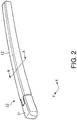
- FIG. 2 is a perspective view illustrating the wiper arm used in the coupling structure of the wiper arm in FIG. 1 .
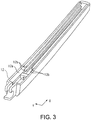
- FIG. 3 is a perspective view illustrating a structure of an arm shank of the wiper arm in FIG. 2 .
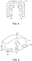
- FIG. 4 is a cross-sectional view cut along line A-A in FIG. 2 .
- the shape of a cross section cut in a Y-direction orthogonal to the longitudinal direction X of the arm shank 12 illustrated in FIG. 2 is substantially a U-shape as illustrated in FIG. 4 .
- the arm shank 12 includes a pair of inner wall surfaces 12a facing each other.
- the coupling engagement portion engaging with the adaptor (coupling member) 13 is formed on the inner wall surface 12a of the arm shank 12, and the adaptor 13 is mounted on an opening side (lower portion side in FIG. 4 ) having the U-shape as illustrated in FIG. 7 (which will be described below).
- the coupling engagement portion of Embodiment 1 is rail portions 12b formed to protrude inward from the inner wall surface 12a of the arm shank 12 illustrated in FIG. 3 , and these rail portions 12b are formed to be continuously connected in the longitudinal direction X of the wiper arm 22. That is, as illustrated in FIGS. 3 and 4 , a cross-sectional shape is a U-shape, and the rail portions 12b are continuously formed on each of the pair of inner wall surfaces 12a facing each other, in other words, the rail portion 12b is a guide portion for the adaptor 13 moving in the longitudinal direction X.
- the rail portions 12b are formed vertically in two stages when the U-shaped opening side is referred to as the lower side.
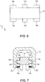
- FIG. 5 is a perspective view illustrating a coupling member of Embodiment 1 embedded in the coupling structure of the wiper arm in FIG. 1 .
- FIG. 6 is a plan view of the coupling member in FIG. 5 .
- the adaptor 13 illustrated in FIG. 5 engages with the arm shank 12 illustrated in FIG. 2 and can slidably move in the longitudinal direction X inside the wiper arm 22. That is, on the right side and the left side toward the inner wall surfaces 12a of the arm shank 12 facing each other in FIG. 4 in the structure illustrated FIG. 5 , a protruding portion 13a engaging with the rail portion 12b on the lower stage side on each of the inner wall surfaces 12a on the right side and the left side of the arm shank 12 is provided on both side surfaces of the adaptor 13.
- the adaptor 13 includes extended portions (portions) 13b formed separately from the protruding portion 13a with a gap therebetween on both side surfaces thereof.
- the two extended portions 13b are provided at the same height on each of the side surfaces of the adaptor 13 of Embodiment 1.
- the right and left protruding portions 13a of the adaptor 13 are guided to the rail portions 12b on the lower stage side provided on the inner wall surfaces 12a of the arm shank 12 and the protruding portions 13a engage with the rail portions 12b, so that the adaptor 13 can slidably move on the rail portions 12b.
- a circular cut-out portion 13c is formed below the protruding portion 13a on both side surfaces of the adaptor 13.
- the cut-out portion 13c is provided below the protruding portion 13a on both side surfaces of the adaptor 13.
- the blade holding member 14 holding the wiper blade 10 illustrated in FIG. 1 is pivotably fitted into the cut-out portions 13c.
- the rail portion 12b of the arm shank 12 on the lower stage side is disposed between the protruding portion 13a and the extended portion 13b of the adaptor 13 as illustrated in FIG. 7 (which will be described below).
- FIG. 7 is a cross-sectional view illustrating a joint structure of the arm shank and the coupling member cut along line A-A in FIG. 2 .
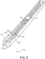
- FIG. 8 is a perspective view illustrating the fixing method for the coupling member in the coupling structure of the wiper arm of Embodiment 1.
- FIG. 9 is a perspective view partially illustrating an engagement structure of the coupling member and a blade holding member in the coupling structure of the wiper arm of Embodiment 1.
- a fixture 17 is mounted in accordance with a position where the adaptor 13 is fixed inside the arm shank 12.
- the adaptor 13 is mounted from the opening part below the arm shank 12 (P1 part in FIG. 8 ), and the right and left extended portions 13b of the adaptor 13 are guided by the rail portions 12b on the lower stage side (upper stage side in FIG. 8 ) provided on the inner wall surfaces 12a of the arm shank 12.
- the extended portions 13b of the adaptor 13 are slidably moved on the rail portions 12b.
- the fixture 17 sets the position of the adaptor 13 in the longitudinal direction X of the arm shank 12 by causing the adaptor 13 to butt the fixture 17.
- the rail portions 12b of the arm shank 12 and the extended portions (portion) 13b of the adaptor 13 are fixed to each other through thermal caulking.
- the extended portions 13b of the adaptor 13 and the rail portions 12b of the arm shank 12 are welded through thermal caulking processing, and the adaptor 13 is fixed at a desired position in the longitudinal direction X of the arm shank 12. Accordingly, weld portions are formed in the N parts.
- the blade holding member 14 is attached to the adaptor 13 which has been attached to the arm shank 12.
- the wiper blade 10 having the blade rubber 20 is mounted in the blade holding member 14.
- projection portions 14a of the blade holding member 14 are fitted into the cut-out portions 13c of the adaptor 13. Accordingly, the blade holding member 14 engages with the adaptor 13.
- the projection portion 14a of the blade holding member 14 and the cut-out portion 13c of the adaptor 13 have a circular shape, the blade holding member 14 is attached pivotably with respect to the adaptor 13.
- the arm shank 12 is formed of polyethylene terephthalate (PET).
- the adaptor 13 is formed of polybutylene terephthalate (PBT).
- the blade holding member 14 is formed of polyacetal (POM).
- the materials for the foregoing members are not limited to the materials described above.
- the coupling structure of the wiper arm 22 of Embodiment 1 since the coupling structure includes the adaptor 13 to connect the arm shank 12 of the wiper arm 22 and the blade holding member 14, the adaptor 13 can be fixed at a plurality of places in the longitudinal direction X of the arm shank 12.
- the wiper arm 22 of one kind which can be attached to the wiper blades 10 of a plurality of types having different lengths. That is, it is possible to provide a coupling structure of the wiper arm 22 which is applicable to the wiper blades 10 of a plurality of types having different lengths.
- the blade holding member 14 can be fixed at an arbitrary place in the longitudinal direction X of the arm shank 12. That is, the wiper blade 10 can be fixed to the arm shank 12 at any position.
- the structure of the arm shank 12 can be a simple structure.
- the structure of the wiper arm 22 on the shank side can be a simple structure by providing the adaptor side with accuracy of a sliding part in the coupling structure of the wiper arm 22. That is, in order to enhance the oscillation accuracy of the arm shank 12, the processing accuracy of the adaptor 13 itself may be further enhanced. It becomes no longer necessary for the arm shank 12 to have enhanced processing accuracy more than necessary by enhancing the processing accuracy of the adaptor 13, so that the structure of the arm shank 12 can be an easy structure.
- the arm shank 12 when the arm shank 12 is processed through molding, since the arm shank 12 has an easy structure, the arm shank 12 can be easily formed through molding.
- the adaptor 13 can also be formed of a material having high sliding properties, so that the reliability of the unit of the wiper arm 22 including the adaptor 13 can be maintained for a long time.
- FIG. 10(a) is a perspective view of the wiper arm 22 having a long wiper blade 10a
- FIG. 10(b) is a plan view illustrating a wiping region 18a of the wiper blade 10a in FIG. 10(a)
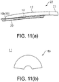
- FIG. 11(a) is a perspective view of the wiper arm 22 having a short wiper blade 10b
- FIG. 11(b) is a plan view illustrating a wiping region 18b of the wiper blade 10b in FIG. 11(a) .
- the wiper blade 10a illustrated in FIGs. 10(a) and 10(b) has a longer length than the wiper blade 10b illustrated in FIG. 11 , regarding the areas of the wiping regions 18a and 18b in the rear glass 11, the area of the wiping region 18a wiped by the wiper blade 10a is larger than the area of the wiping region 18b wiped by the wiper blade 10b.
- the position of the wiper blade 10 can be freely changed in accordance with the layout of the components based on variations in length of the wiper blade 10. Accordingly, the wiper arm 22, the adaptor 13, and the blade holding member 14 can become standard components.
- the fixing position of the adaptor 13 is not misaligned and deterioration in workability for a user can be prevented when the wiper blade 10 is replaced or the like.
- a member such as a screw is not used for fixing the adaptor 13 to the arm shank 12, increase in the number of components can be curbed.
- a coupling structure of a wiper arm of Embodiment 2 will be described. Similar to Embodiment 1, for example, the coupling structure of the wiper arm of Embodiment 2 forms a rear wiper apparatus (not illustrated) wiping the wiping surface of the rear glass 11 (illustrated in FIG. 10 ) provided in a vehicle such as an automobile.
- the coupling structure of the wiper arm of Embodiment 2 uses the arm shank 12 illustrated in FIG. 12 and an adaptor (coupling member) 15 illustrated in FIG. 13 in the coupling structure of the wiper arm 22 illustrated in FIG. 1 . Since the operation method for the wiper arm 22 (refer to FIG. 1 ) is similar to the operation method for the wiper arm 22 of Embodiment 1, description thereof will be omitted.
- the adaptor 15 in the longitudinal direction X of the slender arm shank 12, the adaptor 15 can be fixed at a selective position in the longitudinal direction X thereof.
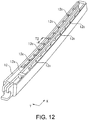
- FIG. 12 is a perspective view illustrating a structure of the arm shank in the wiper arm of Embodiment 2.
- the shape of a cross section cut in the Y-direction orthogonal to the longitudinal direction X of the arm shank 12 is substantially a U-shape.
- the arm shank 12 includes a plurality of coupling engagement portions which can fix the adaptor 15, and the plurality of coupling engagement portions are provided with an interval therebetween in the longitudinal direction X of the arm shank 12.
- the plurality of coupling engagement portions engaging with the adaptor (coupling member) 15 illustrated in FIG. 13 are formed on each of the pair of inner wall surfaces 12a of the arm shank 12 facing each other.
- the adaptor 15 is mounted from the U-shaped opening side, and the adaptor 15 is fixed to any of the plurality of coupling engagement portions.
- the coupling engagement portions of the wiper arm 22 of Embodiment 2 are a plurality of recess portions 12c formed on the (pair of) inner wall surfaces 12a on both sides of the arm shank 12 as illustrated in FIG. 12 .
- the plurality of recess portions 12c are formed in the longitudinal direction X of the arm shank 12. When viewed from the U-shaped opening side of the arm shank 12, unevenness is formed at equal intervals on each of the inner wall surfaces 12a on both sides. In other words, the plurality of recess portions 12c are formed at equal intervals on each of the inner wall surfaces 12a.
- the adaptor 15 can be fitted into the recess portion 12c at any position of the plurality of recess portions 12c.
- the interval T1 between the recess portions 12c adjacent to each other is 20 mm, for example.
- the recess portions 12c are provided at the same positions facing each other. Accordingly, the adaptor 15 can be mounted in any recess portion 12c as illustrated in FIG. 14 (which will be described below).
- FIG. 13 is a perspective view illustrating a coupling member embedded in the coupling structure of the wiper arm of Embodiment 2.
- the adaptor 15 illustrated in FIG. 13 engages with the arm shank 12 illustrated in FIG. 12 and is fixed at a selective position in the longitudinal direction X of the arm shank 12. That is, as illustrated in FIG. 14 (which will be described below), the position of the adaptor 15 can be determined and fixed with respect to the arm shank 12 by inserting the extended portions 15a of the adaptor 15 into any pair of the plurality of recess portions 12c of the arm shank 12 and mounting the adaptor 15.
- the extended portion (protruding portion) 15a is provided at four corners two each on both side surfaces thereof. Moreover, both ends of each extended portion 15a include a claw portion 15b protruding from the extended portion 15a along the side surface.
- a circular cut-out portion 15c is formed below central parts on both side surfaces thereof.
- the blade holding member 14 holding the wiper blade 10 illustrated in FIG. 1 is pivotably fitted into these cut-out portions 15c.
- FIG. 14 is a perspective view partially illustrating a mounting method for the coupling member in the coupling structure of the wiper arm of Embodiment 2.
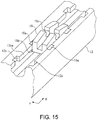
- FIG. 15 is a perspective view partially illustrating details of a mounting structure of the coupling member of Embodiment 2.
- FIG. 16 is a perspective view partially illustrating an engagement structure of the coupling member and a blade holding member in the coupling structure of the wiper arm of Embodiment 2.
- the adaptor 15 When the adaptor 15 is mounted in the arm shank 12, as illustrated in FIG. 14 , in a state where the opening side of the arm shank 12 is directed upward, four extended portions 15a of the adaptor 15 are fitted into the recess portions 12c at predetermined places in the arm shank 12. At this time, as illustrated in FIG. 15 , the adaptor 15 is reliably pressed until the claw portions 15b of the adaptor 15 are hooked at wall portions 12ca forming the recess portions 12c. When the adaptor 15 is pressed into the recess portions 12c, the adaptor 15 may butt inner side surfaces of the arm shank 12. Accordingly, the claw portions 15b can be more reliably hooked at the wall portions 12ca.
- the extended portions 15a of the adaptor 15 are disposed (accommodated) in the recess portions 12c of the arm shank 12, and the claw portions 15b of the adaptor 15 engage with the wall portions 12ca forming the recess portions 12c, so that the position of the adaptor 15 is set and the adaptor 15 is in a state of being fixed to the arm shank 12. That is, position setting and attachment of the adaptor 15 with respect to the arm shank 12 are completed.
- the blade holding member 14 is attached to the adaptor 15 which has been attached to the arm shank 12.
- the wiper blade 10 having the blade rubber 20 is mounted in the blade holding member 14.
- the projection portions 14a of the blade holding member 14 are fitted into the cut-out portions 15c of the adaptor 15. Accordingly, the blade holding member 14 engages with the adaptor 15.
- the projection portion 14a of the blade holding member 14 and the cut-out portion 15c of the adaptor 15 have a circular shape, the blade holding member 14 is attached pivotably with respect to the adaptor 15.
- the coupling structure of the wiper arm 22 of Embodiment 2 since the coupling structure includes the adaptor 15 to connect the arm shank 12 of the wiper arm 22 and the blade holding member 14, the adaptor 15 can be fixed at a plurality of places in the longitudinal direction X of the arm shank 12. That is, since a plurality of fixing places for the adaptor 15 are provided in the arm shank 12, the adaptor 15 can be fixed at a selective position in the longitudinal direction X of the arm shank 12.
- the wiper arm 22 of one kind which can be attached to the wiper blades 10 of a plurality of types having different lengths. That is, it is possible to provide a coupling structure of the wiper arm 22 which is applicable to the wiper blades 10 of a plurality of types having different lengths.
- the structure of the arm shank 12 can be a simple structure.
- the structure of the wiper arm 22 on the shank side can be a simple structure by providing the adaptor side with accuracy of a sliding part in the coupling structure of the wiper arm 22. That is, in order to enhance the oscillation accuracy of the arm shank 12, the processing accuracy of the adaptor 15 itself may be further enhanced.
- the arm shank 12 it becomes no longer necessary for the arm shank 12 to have enhanced processing accuracy more than necessary by enhancing the processing accuracy of the adaptor 15, so that the structure of the arm shank 12 can be an easy structure.
- the arm shank 12 when the arm shank 12 is processed through molding, since the arm shank 12 has an easy structure, the arm shank 12 can be easily formed through molding.
- the adaptor 15 can also be formed of a material having high sliding properties, so that the reliability of the unit of the wiper arm 22 including the adaptor 15 can be maintained for a long time.
- the position of the wiper blade 10 can be selectively changed in accordance with the layout of the components based on variations in length of the wiper blade 10. Accordingly, the wiper arm 22, the adaptor 15, and the blade holding member 14 can become standard components.
- an optimal attachment position for the wiper blade 10 can be set in accordance with the type of automobile.
- the arm shank 12 and the adaptor 15 are fixed to each other through claw fixing by being fitted to each other, the fixing position of the adaptor 15 is not misaligned and deterioration in workability for a user can be prevented when the wiper blade 10 is replaced or the like.
- a member such as a screw is not used for fixing the adaptor 15 to the arm shank 12, increase in the number of components can be curbed.
- a coupling structure of a wiper arm of Embodiment 3 will be described. Similar to Embodiment 1, for example, the coupling structure of the wiper arm of Embodiment 3 forms a rear wiper apparatus (not illustrated) wiping the wiping surface of the rear glass 11 (illustrated in FIG. 10 ) provided in a vehicle such as an automobile.
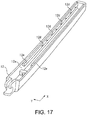
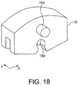
- the coupling structure of the wiper arm of Embodiment 3 uses the arm shank 12 illustrated in FIG. 17 and an adaptor (coupling member) 16 illustrated in FIG. 18 in the coupling structure of the wiper arm 22 illustrated in FIG. 1 . Since the operation method for the wiper arm 22 (refer to FIG. 1 ) is similar to the operation method for the wiper arm 22 of Embodiment 1, description thereof will be omitted.
- the adaptor 16 can be fixed at a selective position in the longitudinal direction X of the arm shank 12.
- FIG. 17 is a perspective view illustrating a structure of the arm shank of the wiper arm of Embodiment 3.
- the shape of a cross section cut in the Y-direction orthogonal to the longitudinal direction X of the arm shank 12 illustrated in FIG. 17 is substantially a U-shape.
- the arm shank 12 includes a plurality of coupling engagement portions which can fix the adaptor 16, and the plurality of coupling engagement portions are provided with an interval therebetween in the longitudinal direction X of the arm shank 12.
- the plurality of coupling engagement portions engaging with the adaptor (coupling member) 16 illustrated in FIG. 18 are formed on each of the pair of inner wall surfaces 12a of the arm shank 12 of the wiper arm 22 facing each other.
- the adaptor 16 is mounted from the U-shaped opening side (P2 part in FIG. 19 ), and the adaptor 16 is fixed to any of the plurality of coupling engagement portions.
- the coupling engagement portions of the wiper arm 22 of Embodiment 3 are a plurality of circular recess portions 12d formed on (pair of) the inner wall surfaces 12a on both sides of the arm shank 12 as illustrated in FIG. 17 .
- the plurality of circular recess portions 12d are formed at equal intervals, for example, near the upper end (near the lower end in FIG. 17 ) of a slide rail 12e formed to protrude inward from the inner wall surface 12a in the longitudinal direction X of the arm shank 12. That is, the slide rail 12e formed to protrude from the inner wall surface 12a, and the plurality of recess portions 12d formed at equal intervals near the upper end of the slide rail 12e are formed such that they communicate with each other.
- the protruding portions 16a of the adaptor 16 illustrated in FIG. 18 are fitted into any pair of these plurality of recess portions 12d. Accordingly, the position of the adaptor 16 is set with respect to the arm shank 12 and is fixed to the arm shank 12. Therefore, in Embodiment 3 as well, the recess portions 12d of the arm shank 12 and the protruding portions 16a of the adaptor 16 are fitted to each other, and the adaptor 16 is fixed to the arm shank 12 due to this fitting.
- FIG. 18 is a perspective view illustrating a coupling member embedded in the coupling structure of the wiper arm of Embodiment 3.
- the adaptor 16 illustrated in FIG. 18 engages with the arm shank 12 illustrated in FIG. 17 and is fixed at a selective position in the longitudinal direction X of the arm shank 12.
- the adaptor 16 includes the protruding portion 16a protruding from each of the side surfaces.
- the protruding portion 16a has a columnar shape.
- the adaptor 16 is mounted from the opening part below the arm shank 12 (P2 part in FIG. 19 ), and the right and left protruding portions 16a are guided by the slide rails 12e provided on the inner wall surfaces 12a of the arm shank 12.
- the position of the adaptor 16 can be determined and fixed with respect to the arm shank 12 by causing the protruding portions 16a of the adaptor 16 to be fitted (press-fitted) into the recess portions 12d at desired positions.
- a circular cut-out portion 16b is formed below the protruding portions 16a on both side surfaces thereof.
- the blade holding member 14 holding the wiper blade 10 illustrated in FIG. 1 is pivotably fitted into these cut-out portion 16b.
- FIG. 19 is a perspective view illustrating a mounting method for the coupling member in the coupling structure of the wiper arm of Embodiment 3.
- FIG. 20 is a side view partially illustrating a press-fitting method for the coupling member of Embodiment 3.
- FIG. 21 is a perspective view partially illustrating a partially broken structure after the coupling member of Embodiment 3 is mounted.
- FIG. 22 is a perspective view partially illustrating an engagement structure of the coupling member and a blade holding member in the coupling structure of the wiper arm of Embodiment 3.
- the adaptor 16 When the adaptor 16 is mounted in the arm shank 12, as indicated with the P2 part in FIG. 19 , in a state where the opening side of the arm shank 12 is directed upward, the adaptor 16 is inserted into the arm shank 12. Thereafter, the adaptor 16 is moved along the slide rails 12e, and the protruding portions 16a are fitted into the recess portions 12d at desired positions as illustrated in FIG. 20 . That is, the protruding portions 16a of the adaptor 16 are lightly press-fitted into the recess portions 12d at desired positions in the arm shank 12. That is, the protruding portions 16a of the adaptor 16 and the recess portions 12d of the arm shank 12 engage with each other through press-fitting. Accordingly, the position of the adaptor 16 is set in the arm shank 12, and the adaptor 16 is in a state of being fixed to the arm shank 12.
- the distance between opening portions 12g facing each other in the recess portion 12d be smaller than the diameter of the protruding portion 16a to the extent that the protruding portion 16a of the adaptor 16 is not easily detached even when a load is applied in a detachment direction.
- a stopper portion 12f protruding inward from this ceiling part is provided in a ceiling part between the inner wall surfaces 12a of the arm shank 12.
- This stopper portion 12f prevents the adaptor 16 from falling off inside the arm shank 12 during wiping in which the wiper arm 22 operates. Therefore, a gap between the stopper portion 12f and the adaptor 16 is a small gap to the extent that the adaptor 16 does not fall off. That is, since the stopper portion 12f is provided in the ceiling part between the inner wall surfaces 12a of the arm shank 12, it is possible to prevent the adaptor 16 from falling off the recess portions 12d when a load in an S-direction is applied to the adaptor 16 during wiping.
- This stopper portion 12f may be a member which is detachably attached using an adhesive material or the like after the adaptor 16 is mounted and may be a member which is integrally formed with the arm shank 12. In addition, the stopper portion 12f may be provided to protrude from the side surfaces of the inner wall surfaces 12a of the arm shank 12.
- the blade holding member 14 is attached to the adaptor 16 which has been attached to the arm shank 12.
- the wiper blade 10 having the blade rubber 20 is mounted in the blade holding member 14.
- the projection portions 14a of the blade holding member 14 are fitted into the cut-out portions 16b of the adaptor 16. Accordingly, the blade holding member 14 engages with the adaptor 16.
- the blade holding member 14 is attached pivotably with respect to the adaptor 16.
- the coupling structure of the wiper arm 22 of Embodiment 3 since the coupling structure includes the adaptor 16 to connect the arm shank 12 of the wiper arm 22 and the blade holding member 14, the adaptor 16 can be fixed at a plurality of places in the longitudinal direction X of the arm shank 12. That is, since a plurality of fixing places for the adaptor 16 are provided in the arm shank 12, the adaptor 16 can be fixed at a selective position in the longitudinal direction X of the arm shank 12.
- the wiper arm 22 of one kind which can be attached to the wiper blades 10 of a plurality of types having different lengths. That is, it is possible to provide a coupling structure of the wiper arm 22 which is applicable to the wiper blades 10 of a plurality of types having different lengths.
- the structure of the arm shank 12 can be a simple structure.
- the structure of the wiper arm 22 on the shank side can be a simple structure by providing the adaptor side with accuracy of a sliding part in the coupling structure of the wiper arm 22. That is, in order to enhance the oscillation accuracy of the arm shank 12, the processing accuracy of the adaptor 16 itself may be further enhanced. It becomes no longer necessary for the arm shank 12 to have enhanced processing accuracy more than necessary by enhancing the processing accuracy of the adaptor 16, so that the structure of the arm shank 12 can be an easy structure.
- the arm shank 12 when the arm shank 12 is processed through molding, since the arm shank 12 has an easy structure, the arm shank 12 can be easily formed through molding.
- the adaptor 16 can also be formed of a material having high sliding properties, so that the reliability of the unit of the wiper arm 22 including the adaptor 16 can be maintained for a long time.
- the position of the wiper blade 10 can be selectively changed in accordance with the layout of the components based on variations in length of the wiper blade 10. Accordingly, the arm shank 12, the adaptor 16, and the blade holding member 14 can become standard components.
- an optimal attachment position for the wiper blade 10(adaptor 16) can be set in accordance with the type of automobile.
- the adaptor 16 is pivotably attached to coupling parts between the arm shank 12 and the protruding portions 16a of the adaptor 16.
- the blade holding member 14 is also pivotably attached for coupling between the cut-out portions 16b of the adaptor 16 and the projection portions 14a of the blade holding member 14 illustrated in FIG. 22 .
- the coupling structure of the wiper arm 22 is applied to a rear wiper apparatus wiping the rear glass 11 of a vehicle such as an automobile.
- the disclosure is not limited thereto and can also be applied to a wiper apparatus installed on a front side of a vehicle such as an automobile, or a wiper apparatus installed in a watercraft, an aircraft, a railroad car, and the like.
Landscapes
- Engineering & Computer Science (AREA)
- Mechanical Engineering (AREA)
- Cleaning Implements For Floors, Carpets, Furniture, Walls, And The Like (AREA)
- Ink Jet (AREA)
- Transmission Devices (AREA)
- Pivots And Pivotal Connections (AREA)
Claims (3)
- Kupplungsstruktur eines Wischerarms (22), gekoppelt mit einem Blatt-Halteelement (14) in einer anbringbaren/abnehmbaren Weise an dem Wischerarm (22), wobei die Kupplungsstruktur umfasst:den Wischerarm (22);ein Kupplungselement (13), das an einem Armschaft (12) befestigt ist, der den Wischerarm (22) bildet; unddas Blatt-Halteelement (14), das mit dem Kupplungselement (13) in Eingriff steht und ein Wischerblatt (10) hält,wobei das Kupplungselement (13) zwischen dem Armschaft (12) und dem Blatt-Halteelement (14) angeordnet ist, und
wobei der Armschaft (12) einen Kupplungseingriffsabschnitt (12b) umfasst, der in der Lage ist, das Kupplungselement (13) an irgendeiner Position in einer Längsrichtung des Armschafts (12) zu fixieren,
wobei der Armschaft (12) ein Paar von Innenwandflächen (12a) umfasst, die einander zugewandt sind,
wobei der Kupplungseingriffsabschnitt (12b), der mit dem Kupplungselement (13) in Eingriff steht, an jeder der Innenwandflächen (12a) ausgebildet ist, und
wobei der Kupplungseingriffsabschnitt (12b) in der Längsrichtung des Armschaftes (12) durchgehend verbunden ist, wobei die Kupplungsstruktur dadurch gekennzeichnet ist, dass
der Kupplungseingriffsabschnitt (12b) ein Schienenabschnitt ist, der von der Innenwandfläche (12a) des Armschafts (12) vorsteht, und
wobei das Kupplungselement (13) einen vorstehenden Abschnitt (13a) aufweist, der mit dem Schienenabschnitt in Eingriff steht. - Kupplungsstruktur eines Wischerarms (22) gemäß Anspruch 1, wobei ein Schweißabschnitt (N) ausgebildet ist, der einen Abschnitt des Kupplungseingriffsabschnitts (12b) und einen Abschnitt des Kupplungselements (13) miteinander verbindet.
- Kupplungsstruktur eines Wischerarms (22) gemäß Anspruch 1,
wobei das Kupplungselement (13) einen verlängerten Abschnitt (13b) umfasst,
wobei der verlängerte Abschnitt (13b) getrennt von dem vorstehenden Abschnitt (13a) mit einem Spalt dazwischen angeordnet ist, und
wobei der Schienenabschnitt des Armschaftes (12) zwischen dem vorstehenden Abschnitt (13a) und dem verlängerten Abschnitt (13b) in dem Kupplungselement (13) angeordnet ist.
Applications Claiming Priority (1)
| Application Number | Priority Date | Filing Date | Title |
|---|---|---|---|
| JP2018142244A JP7034857B2 (ja) | 2018-07-30 | 2018-07-30 | ワイパアームの連結構造 |
Publications (2)
| Publication Number | Publication Date |
|---|---|
| EP3604053A1 EP3604053A1 (de) | 2020-02-05 |
| EP3604053B1 true EP3604053B1 (de) | 2021-04-28 |
Family
ID=67297063
Family Applications (1)
| Application Number | Title | Priority Date | Filing Date |
|---|---|---|---|
| EP19186318.2A Active EP3604053B1 (de) | 2018-07-30 | 2019-07-15 | Kopplungsstruktur eines wischerarms |
Country Status (3)
| Country | Link |
|---|---|
| EP (1) | EP3604053B1 (de) |
| JP (1) | JP7034857B2 (de) |
| CN (1) | CN110775020B (de) |
Family Cites Families (8)
| Publication number | Priority date | Publication date | Assignee | Title |
|---|---|---|---|---|
| DE102010052308A1 (de) * | 2010-11-16 | 2012-05-16 | Daimler Ag | Wischarmanordnung und Verfahren zum Verbinden eines Wischblatts mit einem Wischarm |
| DE102012011660A1 (de) * | 2012-06-13 | 2013-12-19 | Daimler Ag | Wischblatt, Wischarm und Verbindungsanordnung für eine Scheibenwischanlage eines Fahrzeugs |
| DE102012110859A1 (de) * | 2012-11-12 | 2014-05-15 | Valeo Wischersysteme Gmbh | Wischarm für ein Wischblatt zum Reinigen einer Fahrzeugscheibe sowie Wischvorrichtung zum Reinigen einer Fahrzeugscheibe |
| DE102012024966A1 (de) * | 2012-12-20 | 2013-08-01 | Daimler Ag | Wischarm für eine Scheibenwischanlage eines Fahrzeugs und Verfahren zum Anbringen eines Wischblatts an einem Wischarm |
| JP6348334B2 (ja) | 2014-05-08 | 2018-06-27 | 株式会社ミツバ | ワイパブレードの連結構造 |
| FR3022201B1 (fr) * | 2014-06-11 | 2018-01-26 | Renault S.A.S | Bras balai pour un systeme d'essuyage de lunette arriere d'un vehicule automobile |
| JP6017647B1 (ja) * | 2015-07-27 | 2016-11-02 | 日本ワイパブレード株式会社 | ワイパー組み立て体 |
| JP6177979B2 (ja) * | 2016-09-21 | 2017-08-09 | アスモ株式会社 | ワイパブレード及びワイパ |
-
2018
- 2018-07-30 JP JP2018142244A patent/JP7034857B2/ja active Active
-
2019
- 2019-07-15 EP EP19186318.2A patent/EP3604053B1/de active Active
- 2019-07-22 CN CN201910660900.1A patent/CN110775020B/zh active Active
Non-Patent Citations (1)
| Title |
|---|
| None * |
Also Published As
| Publication number | Publication date |
|---|---|
| CN110775020A (zh) | 2020-02-11 |
| JP7034857B2 (ja) | 2022-03-14 |
| CN110775020B (zh) | 2022-12-27 |
| EP3604053A1 (de) | 2020-02-05 |
| JP2020019293A (ja) | 2020-02-06 |
Similar Documents
| Publication | Publication Date | Title |
|---|---|---|
| CZ20013785A3 (cs) | List stěrače skel, zejména vozidel | |
| CN104080665B (zh) | 用于清洁车辆窗户的雨刷装置 | |
| US8429786B2 (en) | Connection device for the articulated connection of a wiper blade to a wiper arm | |
| US20070011840A1 (en) | Windscreen wiper arm | |
| CN102985301B (zh) | 梁片式风挡刮水器组件 | |
| US20110247166A1 (en) | Connecting device for the articulated connection of a wiper blade to a wiper arm | |
| JP2014509985A (ja) | フロントガラスワイパー装置 | |
| JP2009051503A (ja) | 風防ガラス用のワイパブレードをワイパアームに固定するアダプタ | |
| JP2002536244A (ja) | ワイパアーム | |
| JP2005502546A (ja) | ヒンジ結合されたワイパブレードを備えたワイパアーム | |
| US20170136999A1 (en) | A windscreen wiper device | |
| KR20170056456A (ko) | 앞유리 와이퍼 블레이드 홀더를 구동 아암에 연결하기 위한 시스템용 요소 | |
| US20130340195A1 (en) | Wiper blade adapter device, in particular for a motor vehicle windscreen wiper device | |
| JP2009501664A (ja) | フロントガラス・ワイパー装置 | |
| EP3604053B1 (de) | Kopplungsstruktur eines wischerarms | |
| CN103228497B (zh) | 风挡刮雨器装置 | |
| KR20160084388A (ko) | 윈드스크린 와이퍼 장치 | |
| EP2790970B1 (de) | Scheibenwischerarm | |
| US11077831B2 (en) | Windscreen wiper device | |
| US20170197592A1 (en) | Windscreen wiper device | |
| KR100799087B1 (ko) | 윈드스크린 와이퍼용 조인트부 | |
| KR101305350B1 (ko) | 와이퍼 블레이드 조립체 | |
| US20200254977A1 (en) | A windscreen wiper device | |
| JP2020019294A (ja) | ワイパアームの連結構造 | |
| JP2018016186A (ja) | ワイパーアーム |
Legal Events
| Date | Code | Title | Description |
|---|---|---|---|
| PUAI | Public reference made under article 153(3) epc to a published international application that has entered the european phase |
Free format text: ORIGINAL CODE: 0009012 |
|
| STAA | Information on the status of an ep patent application or granted ep patent |
Free format text: STATUS: REQUEST FOR EXAMINATION WAS MADE |
|
| 17P | Request for examination filed |
Effective date: 20190715 |
|
| AK | Designated contracting states |
Kind code of ref document: A1 Designated state(s): AL AT BE BG CH CY CZ DE DK EE ES FI FR GB GR HR HU IE IS IT LI LT LU LV MC MK MT NL NO PL PT RO RS SE SI SK SM TR |
|
| AX | Request for extension of the european patent |
Extension state: BA ME |
|
| RBV | Designated contracting states (corrected) |
Designated state(s): AL AT BE BG CH CY CZ DE DK EE ES FI FR GB GR HR HU IE IS IT LI LT LU LV MC MK MT NL NO PL PT RO RS SE SI SK SM TR |
|
| GRAP | Despatch of communication of intention to grant a patent |
Free format text: ORIGINAL CODE: EPIDOSNIGR1 |
|
| STAA | Information on the status of an ep patent application or granted ep patent |
Free format text: STATUS: GRANT OF PATENT IS INTENDED |
|
| INTG | Intention to grant announced |
Effective date: 20210112 |
|
| GRAS | Grant fee paid |
Free format text: ORIGINAL CODE: EPIDOSNIGR3 |
|
| GRAA | (expected) grant |
Free format text: ORIGINAL CODE: 0009210 |
|
| STAA | Information on the status of an ep patent application or granted ep patent |
Free format text: STATUS: THE PATENT HAS BEEN GRANTED |
|
| AK | Designated contracting states |
Kind code of ref document: B1 Designated state(s): AL AT BE BG CH CY CZ DE DK EE ES FI FR GB GR HR HU IE IS IT LI LT LU LV MC MK MT NL NO PL PT RO RS SE SI SK SM TR |
|
| REG | Reference to a national code |
Ref country code: GB Ref legal event code: FG4D |
|
| REG | Reference to a national code |
Ref country code: CH Ref legal event code: EP |
|
| REG | Reference to a national code |
Ref country code: AT Ref legal event code: REF Ref document number: 1386736 Country of ref document: AT Kind code of ref document: T Effective date: 20210515 |
|
| REG | Reference to a national code |
Ref country code: DE Ref legal event code: R096 Ref document number: 602019004207 Country of ref document: DE |
|
| REG | Reference to a national code |
Ref country code: IE Ref legal event code: FG4D |
|
| REG | Reference to a national code |
Ref country code: LT Ref legal event code: MG9D |
|
| REG | Reference to a national code |
Ref country code: AT Ref legal event code: MK05 Ref document number: 1386736 Country of ref document: AT Kind code of ref document: T Effective date: 20210428 |
|
| PG25 | Lapsed in a contracting state [announced via postgrant information from national office to epo] |
Ref country code: HR Free format text: LAPSE BECAUSE OF FAILURE TO SUBMIT A TRANSLATION OF THE DESCRIPTION OR TO PAY THE FEE WITHIN THE PRESCRIBED TIME-LIMIT Effective date: 20210428 Ref country code: LT Free format text: LAPSE BECAUSE OF FAILURE TO SUBMIT A TRANSLATION OF THE DESCRIPTION OR TO PAY THE FEE WITHIN THE PRESCRIBED TIME-LIMIT Effective date: 20210428 Ref country code: FI Free format text: LAPSE BECAUSE OF FAILURE TO SUBMIT A TRANSLATION OF THE DESCRIPTION OR TO PAY THE FEE WITHIN THE PRESCRIBED TIME-LIMIT Effective date: 20210428 Ref country code: NL Free format text: LAPSE BECAUSE OF FAILURE TO SUBMIT A TRANSLATION OF THE DESCRIPTION OR TO PAY THE FEE WITHIN THE PRESCRIBED TIME-LIMIT Effective date: 20210428 Ref country code: AT Free format text: LAPSE BECAUSE OF FAILURE TO SUBMIT A TRANSLATION OF THE DESCRIPTION OR TO PAY THE FEE WITHIN THE PRESCRIBED TIME-LIMIT Effective date: 20210428 Ref country code: BG Free format text: LAPSE BECAUSE OF FAILURE TO SUBMIT A TRANSLATION OF THE DESCRIPTION OR TO PAY THE FEE WITHIN THE PRESCRIBED TIME-LIMIT Effective date: 20210728 |
|
| PG25 | Lapsed in a contracting state [announced via postgrant information from national office to epo] |
Ref country code: NO Free format text: LAPSE BECAUSE OF FAILURE TO SUBMIT A TRANSLATION OF THE DESCRIPTION OR TO PAY THE FEE WITHIN THE PRESCRIBED TIME-LIMIT Effective date: 20210728 Ref country code: PL Free format text: LAPSE BECAUSE OF FAILURE TO SUBMIT A TRANSLATION OF THE DESCRIPTION OR TO PAY THE FEE WITHIN THE PRESCRIBED TIME-LIMIT Effective date: 20210428 Ref country code: LV Free format text: LAPSE BECAUSE OF FAILURE TO SUBMIT A TRANSLATION OF THE DESCRIPTION OR TO PAY THE FEE WITHIN THE PRESCRIBED TIME-LIMIT Effective date: 20210428 Ref country code: RS Free format text: LAPSE BECAUSE OF FAILURE TO SUBMIT A TRANSLATION OF THE DESCRIPTION OR TO PAY THE FEE WITHIN THE PRESCRIBED TIME-LIMIT Effective date: 20210428 Ref country code: PT Free format text: LAPSE BECAUSE OF FAILURE TO SUBMIT A TRANSLATION OF THE DESCRIPTION OR TO PAY THE FEE WITHIN THE PRESCRIBED TIME-LIMIT Effective date: 20210830 Ref country code: SE Free format text: LAPSE BECAUSE OF FAILURE TO SUBMIT A TRANSLATION OF THE DESCRIPTION OR TO PAY THE FEE WITHIN THE PRESCRIBED TIME-LIMIT Effective date: 20210428 Ref country code: GR Free format text: LAPSE BECAUSE OF FAILURE TO SUBMIT A TRANSLATION OF THE DESCRIPTION OR TO PAY THE FEE WITHIN THE PRESCRIBED TIME-LIMIT Effective date: 20210729 Ref country code: IS Free format text: LAPSE BECAUSE OF FAILURE TO SUBMIT A TRANSLATION OF THE DESCRIPTION OR TO PAY THE FEE WITHIN THE PRESCRIBED TIME-LIMIT Effective date: 20210828 |
|
| REG | Reference to a national code |
Ref country code: NL Ref legal event code: MP Effective date: 20210428 |
|
| PG25 | Lapsed in a contracting state [announced via postgrant information from national office to epo] |
Ref country code: EE Free format text: LAPSE BECAUSE OF FAILURE TO SUBMIT A TRANSLATION OF THE DESCRIPTION OR TO PAY THE FEE WITHIN THE PRESCRIBED TIME-LIMIT Effective date: 20210428 Ref country code: ES Free format text: LAPSE BECAUSE OF FAILURE TO SUBMIT A TRANSLATION OF THE DESCRIPTION OR TO PAY THE FEE WITHIN THE PRESCRIBED TIME-LIMIT Effective date: 20210428 Ref country code: SK Free format text: LAPSE BECAUSE OF FAILURE TO SUBMIT A TRANSLATION OF THE DESCRIPTION OR TO PAY THE FEE WITHIN THE PRESCRIBED TIME-LIMIT Effective date: 20210428 Ref country code: SM Free format text: LAPSE BECAUSE OF FAILURE TO SUBMIT A TRANSLATION OF THE DESCRIPTION OR TO PAY THE FEE WITHIN THE PRESCRIBED TIME-LIMIT Effective date: 20210428 Ref country code: RO Free format text: LAPSE BECAUSE OF FAILURE TO SUBMIT A TRANSLATION OF THE DESCRIPTION OR TO PAY THE FEE WITHIN THE PRESCRIBED TIME-LIMIT Effective date: 20210428 Ref country code: DK Free format text: LAPSE BECAUSE OF FAILURE TO SUBMIT A TRANSLATION OF THE DESCRIPTION OR TO PAY THE FEE WITHIN THE PRESCRIBED TIME-LIMIT Effective date: 20210428 Ref country code: CZ Free format text: LAPSE BECAUSE OF FAILURE TO SUBMIT A TRANSLATION OF THE DESCRIPTION OR TO PAY THE FEE WITHIN THE PRESCRIBED TIME-LIMIT Effective date: 20210428 |
|
| REG | Reference to a national code |
Ref country code: DE Ref legal event code: R097 Ref document number: 602019004207 Country of ref document: DE |
|
| PLBE | No opposition filed within time limit |
Free format text: ORIGINAL CODE: 0009261 |
|
| STAA | Information on the status of an ep patent application or granted ep patent |
Free format text: STATUS: NO OPPOSITION FILED WITHIN TIME LIMIT |
|
| PG25 | Lapsed in a contracting state [announced via postgrant information from national office to epo] |
Ref country code: MC Free format text: LAPSE BECAUSE OF FAILURE TO SUBMIT A TRANSLATION OF THE DESCRIPTION OR TO PAY THE FEE WITHIN THE PRESCRIBED TIME-LIMIT Effective date: 20210428 |
|
| REG | Reference to a national code |
Ref country code: BE Ref legal event code: MM Effective date: 20210731 |
|
| 26N | No opposition filed |
Effective date: 20220131 |
|
| PG25 | Lapsed in a contracting state [announced via postgrant information from national office to epo] |
Ref country code: IS Free format text: LAPSE BECAUSE OF FAILURE TO SUBMIT A TRANSLATION OF THE DESCRIPTION OR TO PAY THE FEE WITHIN THE PRESCRIBED TIME-LIMIT Effective date: 20210828 Ref country code: LU Free format text: LAPSE BECAUSE OF NON-PAYMENT OF DUE FEES Effective date: 20210715 Ref country code: AL Free format text: LAPSE BECAUSE OF FAILURE TO SUBMIT A TRANSLATION OF THE DESCRIPTION OR TO PAY THE FEE WITHIN THE PRESCRIBED TIME-LIMIT Effective date: 20210428 |
|
| PG25 | Lapsed in a contracting state [announced via postgrant information from national office to epo] |
Ref country code: IT Free format text: LAPSE BECAUSE OF FAILURE TO SUBMIT A TRANSLATION OF THE DESCRIPTION OR TO PAY THE FEE WITHIN THE PRESCRIBED TIME-LIMIT Effective date: 20210428 Ref country code: IE Free format text: LAPSE BECAUSE OF NON-PAYMENT OF DUE FEES Effective date: 20210715 Ref country code: BE Free format text: LAPSE BECAUSE OF NON-PAYMENT OF DUE FEES Effective date: 20210731 |
|
| REG | Reference to a national code |
Ref country code: CH Ref legal event code: PL |
|
| PG25 | Lapsed in a contracting state [announced via postgrant information from national office to epo] |
Ref country code: LI Free format text: LAPSE BECAUSE OF NON-PAYMENT OF DUE FEES Effective date: 20220731 Ref country code: CH Free format text: LAPSE BECAUSE OF NON-PAYMENT OF DUE FEES Effective date: 20220731 |
|
| PG25 | Lapsed in a contracting state [announced via postgrant information from national office to epo] |
Ref country code: CY Free format text: LAPSE BECAUSE OF FAILURE TO SUBMIT A TRANSLATION OF THE DESCRIPTION OR TO PAY THE FEE WITHIN THE PRESCRIBED TIME-LIMIT Effective date: 20210428 |
|
| PG25 | Lapsed in a contracting state [announced via postgrant information from national office to epo] |
Ref country code: HU Free format text: LAPSE BECAUSE OF FAILURE TO SUBMIT A TRANSLATION OF THE DESCRIPTION OR TO PAY THE FEE WITHIN THE PRESCRIBED TIME-LIMIT; INVALID AB INITIO Effective date: 20190715 |
|
| GBPC | Gb: european patent ceased through non-payment of renewal fee |
Effective date: 20230715 |
|
| PG25 | Lapsed in a contracting state [announced via postgrant information from national office to epo] |
Ref country code: MK Free format text: LAPSE BECAUSE OF FAILURE TO SUBMIT A TRANSLATION OF THE DESCRIPTION OR TO PAY THE FEE WITHIN THE PRESCRIBED TIME-LIMIT Effective date: 20210428 Ref country code: GB Free format text: LAPSE BECAUSE OF NON-PAYMENT OF DUE FEES Effective date: 20230715 |
|
| PG25 | Lapsed in a contracting state [announced via postgrant information from national office to epo] |
Ref country code: TR Free format text: LAPSE BECAUSE OF FAILURE TO SUBMIT A TRANSLATION OF THE DESCRIPTION OR TO PAY THE FEE WITHIN THE PRESCRIBED TIME-LIMIT Effective date: 20210428 |
|
| PG25 | Lapsed in a contracting state [announced via postgrant information from national office to epo] |
Ref country code: MT Free format text: LAPSE BECAUSE OF FAILURE TO SUBMIT A TRANSLATION OF THE DESCRIPTION OR TO PAY THE FEE WITHIN THE PRESCRIBED TIME-LIMIT Effective date: 20210428 |
|
| PGFP | Annual fee paid to national office [announced via postgrant information from national office to epo] |
Ref country code: FR Payment date: 20250610 Year of fee payment: 7 |
|
| PGFP | Annual fee paid to national office [announced via postgrant information from national office to epo] |
Ref country code: DE Payment date: 20250528 Year of fee payment: 7 |