EP3603775B1 - Fluidtrennelement und teleskopische präventionsplatte - Google Patents
Fluidtrennelement und teleskopische präventionsplatte Download PDFInfo
- Publication number
- EP3603775B1 EP3603775B1 EP18778151.3A EP18778151A EP3603775B1 EP 3603775 B1 EP3603775 B1 EP 3603775B1 EP 18778151 A EP18778151 A EP 18778151A EP 3603775 B1 EP3603775 B1 EP 3603775B1
- Authority
- EP
- European Patent Office
- Prior art keywords
- annular portion
- telescoping
- spirally wound
- outer shell
- axially
- Prior art date
- Legal status (The legal status is an assumption and is not a legal conclusion. Google has not performed a legal analysis and makes no representation as to the accuracy of the status listed.)
- Active
Links
Images





Classifications
-
- B—PERFORMING OPERATIONS; TRANSPORTING
- B01—PHYSICAL OR CHEMICAL PROCESSES OR APPARATUS IN GENERAL
- B01D—SEPARATION
- B01D63/00—Apparatus in general for separation processes using semi-permeable membranes
- B01D63/10—Spiral-wound membrane modules
- B01D63/106—Anti-Telescopic-Devices [ATD]
-
- B—PERFORMING OPERATIONS; TRANSPORTING
- B01—PHYSICAL OR CHEMICAL PROCESSES OR APPARATUS IN GENERAL
- B01D—SEPARATION
- B01D63/00—Apparatus in general for separation processes using semi-permeable membranes
- B01D63/10—Spiral-wound membrane modules
- B01D63/103—Details relating to membrane envelopes
-
- B—PERFORMING OPERATIONS; TRANSPORTING
- B01—PHYSICAL OR CHEMICAL PROCESSES OR APPARATUS IN GENERAL
- B01D—SEPARATION
- B01D65/00—Accessories or auxiliary operations, in general, for separation processes or apparatus using semi-permeable membranes
- B01D65/003—Membrane bonding or sealing
-
- C—CHEMISTRY; METALLURGY
- C02—TREATMENT OF WATER, WASTE WATER, SEWAGE, OR SLUDGE
- C02F—TREATMENT OF WATER, WASTE WATER, SEWAGE, OR SLUDGE
- C02F1/00—Treatment of water, waste water, or sewage
- C02F1/44—Treatment of water, waste water, or sewage by dialysis, osmosis or reverse osmosis
-
- B—PERFORMING OPERATIONS; TRANSPORTING
- B01—PHYSICAL OR CHEMICAL PROCESSES OR APPARATUS IN GENERAL
- B01D—SEPARATION
- B01D2313/00—Details relating to membrane modules or apparatus
- B01D2313/04—Specific sealing means
- B01D2313/041—Gaskets or O-rings
-
- B—PERFORMING OPERATIONS; TRANSPORTING
- B01—PHYSICAL OR CHEMICAL PROCESSES OR APPARATUS IN GENERAL
- B01D—SEPARATION
- B01D2313/00—Details relating to membrane modules or apparatus
- B01D2313/08—Flow guidance means within the module or the apparatus
-
- B—PERFORMING OPERATIONS; TRANSPORTING
- B01—PHYSICAL OR CHEMICAL PROCESSES OR APPARATUS IN GENERAL
- B01D—SEPARATION
- B01D2315/00—Details relating to the membrane module operation
- B01D2315/02—Rotation or turning
Definitions
- the present invention relates to a fluid separation element used suitably for a reverse osmosis apparatus, a nanofiltration apparatus, an ultrafiltration apparatus, a microfiltration apparatus, etc.
- Examples of forms of fluid separation elements include a type using a hollow fiber membrane, a plate frame type of a flat membrane, and a spiral type.
- the spiral type fluid separation element has a structure in which a separation membrane is spirally wound around a water collection tube together with a permeate channel material and a raw water channel material. Raw water is supplied from one end surface of the fluid separation element, and treated by the separation membrane. The permeate which has been permeated through the separation membrane is taken out from the water collection tube, while the raw water which has not been permeated through the separation membrane is discharged as concentrated liquid from the other end surface of the fluid separation element.
- an outer circumferential portion thereof is reinforced with an outer shell including fiber reinforced plastic (Fiber Reinforced Plastic (FRP)) of glass fiber and epoxy resin, and anti-telescoping plates are attached to the axially both ends of the fluid separation element.
- FRP Fiber Reinforced Plastic
- a seal member called a brine seal is provided on the anti-telescoping plate on the upstream side of the fluid separation element so as to prevent raw water from passing through a short path into a gap between the outer shell of the fluid separation element and a pressure vessel.
- the brine seal may be an O-ring or the like, but a U-seal or the like is often used as the brine seal owing to its loadability to the pressure vessel.
- fluid separation elements When such fluid separation elements are used, about one to six fluid separation elements are loaded and used in series in a pressure vessel, and a number of such pressure vessels are placed on a rack to perform large-volume treatment.
- a fluid separation element has been known in which a groove is provided in each anti-telescoping plate so that an outer shell of the fluid separation element can be inserted externally in the groove in order to prevent the outer shell from moving in an axial direction of the fluid separation element (for example, see Patent Literature 1).
- an anti-telescoping member for membrane elements is known from Patent Literature 2 having a plurality of types of undulations of different shapes on the circumference of an extension that extends from the main body.
- the exterior finishing material of the membrane roll body is attached to the circumference of the extension so that the plurality of types of undulations are in contact with the exterior finishing material.
- JP2010194406 , JP2012183464 , US2014353239 and US2016038881 disclose spiral wound membrane modules with anti-telescoping devices.
- the spirally wound body may rotate together to cause collapse of the spirally wound body structure or damage on a surface of the separation membrane.
- An object lying in the background of the present invention is to suppress the outer shell and each anti-telescoping plate from being displaced from each other in the rotation direction when raw water is supplied to the fluid separation element. Specifically, an object of the present invention is to suppress the outer shell from rotating even if force is applied in a direction to rotate the outer shell relatively to the each anti-telescoping plate when the fluid separation element loaded in a pressure vessel is operated.
- An advantageous effect obtained by the fluid separation element according to the present invention is that it is possible to suppress the outer shell from rotating relatively to each anti-telescoping plate even if force is generated in a direction to rotate the outer shell or the anti-telescoping plate when the fluid separation element is in use.
- the spirally wound body and each anti-telescoping plate are fixed by a tape when the fluid separation element is manufactured, but the third annular portion and the first annular portion are covered with the tape on this occasion.
- the depressions may exhibit no effect.
- the positions of the depressions are limited to a side surface of the second annular portion on the spirally wound body side, the depressions can exhibit an effect even if the spirally wound body and the each anti-telescoping plate are fixed by a tape.
- the fluid separation element can be manufactured effectively.
- Fig. 1 is a schematic partial development showing an embodiment of a fluid separation element to which the present invention is applied.
- the fluid separation element is a spiral type fluid separation element, in which one unit or a plurality of units are prepared and spirally wound around a water collection tube 1.
- Each unit includes a first separation membrane 3, a second separation membrane 4, a permeate channel material 5 and a raw water channel material 6.
- the first separation membrane 3 and the second separation membrane 4 are bonded to each other at their three sides to form an envelope-like membrane into which the permeate channel material 5 is inserted.
- the envelope-like membrane including the first separation membrane 3 and the second separation membrane 4 has a structure in which the first separation membrane 3 and the second separation membrane 4 are bonded at, of the four sides of the envelope-like membrane, all the sides except for the side on the water collection tube 1 side.
- the envelope-like membrane is open on the water collection tube 1 side.
- Raw water 2 is supplied from one end surface of the fluid separation element, and treated in an effective membrane portion 12 (see Fig. 4 ) which is a part where the first separation membrane 3 and the second separation membrane 4 are not bonded with each other.
- Permeate 8 which has been permeated through the separation membranes 3 and 4 is taken out from the water collection tube 1, and the raw water 2 which has not been permeated through the separation membranes 3 and 4 is discharged as concentrate 7 from the other end surface of the fluid separation element.
- the spiral type fluid separation element has a form in which an outer circumferential portion thereof is reinforced with an outer shell 11, and anti-telescoping plates 9 are attached to the longitudinally both ends.
- raw materials of the outer shell include fiber reinforced plastic (FRP) containing urethane resin, epoxy resin or the like, a plastic film containing polyethylene or polypropylene, etc.
- the outer shell is preferably an FRP shell including fiber reinforced plastic (FRP) from the viewpoint of pressure resistance, and more preferably an FPR shell including fiber reinforced plastic (FRP) containing glass fiber and epoxy resin from the viewpoint of heat resistance.
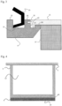
- Fig. 2 is a sectional enlarged view showing, of the spiral type fluid separation element according to the present invention, vicinities of a contact portion between an outer circumferential annular portion of an anti-telescoping plate 9 and the outer shell 11.
- Fig. 3 is a sectional enlarged view showing, of the spiral type fluid separation element according to the present invention, the vicinities of the contact portion between the outer circumferential annular portion of the anti-telescoping plate 9 and the outer shell 11 when a brine seal 10 is attached.
- Each anti-telescoping plate 9 includes a first annular portion 19 which can retain the outer shell 11, and a second annular portion 20 which is formed on the axially outer side of the first annular portion and in which an outer end portion of the outer shell 11 can be locked therein.
- the anti-telescoping plate 9 further includes a third annular portion 18 which is formed on the axially inner side of the first annular portion 19 and has an annular shape with a larger outer diameter than that of the first annular portion.
- a step is made between the first annular portion 19 and the third annular portion 18 so that the outer shell 11 can be locked more easily, and axial displacement between the outer shell and the anti-telescoping plate can be more suppressed.
- a depression 25 is provided on a side surface of the second annular portion 20 on the axially inner side (specifically a side surface on the spirally wound body side when the anti-telescoping plate 9 is attached to the fluid separation element).
- the anti-telescoping plate 9 further includes a fourth annular portion 21 which is formed on the axially outer side of the second annular portion 20 and in which the brine seal 10 can be externally inserted thereinto as shown in Fig. 3 , and a fifth annular portion 22 which is formed on the axially outer side of the fourth annular portion 21 and in which the brine seal 10 can be locked therein.
- a fourth annular portion 21 and the fifth annular portion 22 are absent, the effects of the present invention can be exhibited.
- a part of an outer side surface of a second annular portion of the anti-telescoping plate has a concavo-convex portion
- the concavo-convex portion has a complementary shape to a concavo-convex portion on an anti-telescoping plate opposed thereto.
- the concavo-convex portion bites the opposed concavo-convex portion complementarily so that the anti-telescoping plates opposed to each other can be sealed liquid-tightly, thereby playing a role as the brine seal 10.
- the fluid separation element according to the present invention can be manufactured as follows. That is, the separation membranes 3 and 4 being formed into an envelope-like membrane and having the permeate channel material 5 inserted thereinto are wound around the water collection tube 1 together with the raw water channel material 6 so as to form a spirally wound body 17.
- the anti-telescoping plates 9 according to the present invention are fixed to the end surfaces of the spirally wound body 17 by taping or the like. Then, a resin composition for forming an outer shell is wound on the outer circumference of the spirally wound body 17 and the anti-telescoping plates 9. After that, the resin composition is hardened to produce the fluid separation element according to the present invention.
- the outer shell 11 formed after the resin composition is hardened is firmly fixed to the anti-telescoping plates 9. Therefore, even if force is applied in a direction to rotate the outer shell relatively to each anti-telescoping plate, the outer shell can be suppressed from rotating.
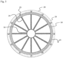
- Fig. 5 is a view in which, among shapes which the anti-telescoping plate according to the present invention can be formed into, a preferred shape is observed from the spirally wound body side.
- Each anti-telescoping plate 9 is constituted by an outer ring portion 15 constituted by the third annular portion 18, the first annular portion 19, the second annular portion 20, the fourth annular portion 21 and the fifth annular portion 22 as shown in Fig. 2 ; an inner ring portion 16 formed of a ring with a smaller outer diameter than that of the outer ring portion 15 as shown in Fig. 5 ; and spokes 24 connecting the outer ring portion 15 and the inner ring portion 16 with each other.
- the inner diameter of the inner ring portion 16 is larger than the outer diameter of the water collection tube 1.
- the depression 25 is provided on a side surface 23 (side surface of a second annular portion on a spirally wound body side) of the second annular portion 20 on the spirally wound body side of each anti-telescoping plate 9 in order to prevent the outer shell 11 from rotating relatively to the each anti-telescoping plate 9.
- the outer shell 11 and the anti-telescoping plate 9 are externally inserted into the first annular portion 19, and brought into contact with the second annular portion 20.
- a part of the outer shell 11 enters the depression 25 on the second annular portion 20 so as to have a shape in which an anchor is driven from the outer shell 11 to the anti-telescoping plate 9.
- the outer shell 11 is suppressed from rotating relatively to the each anti-telescoping plate 9.
- a sectional shape or position of the depression 25 appearing when the second annular portion 20 is sectionally cut by a plane passing the central axis of a corresponding one of the anti-telescoping plates 9 preferably differs in the circumferential direction of the second annular portion 20.
- the phrase "a sectional shape or position of the depression 25 appearing when the second annular portion 20 is sectionally cut differs in the circumferential direction of the second annular portion 20" means that the shape or position appearing when the second annular portion 20 is sectionally cut by an arbitrary plane passing the central axis of a corresponding one of the anti-telescoping plates 9 may differ depending on the planes.
- the brine seal 10 is externally inserted to the anti-telescoping plate 9 on the upstream side of the fluid separation element so as to prevent raw water from passing through a short path into a gap between the outer shell of the fluid separation element and a pressure vessel.
- the brine seal may be an O-ring or the like, but a U-seal, a split ring seal or the like is often used as the brine seal owing to its loadability to the pressure vessel.
- a U-part thereof is opened when fluid flows therein from the upstream side, so that the anti-telescoping plate and the pressure vessel can be sealed liquid-tightly.
- FIG. 5 is a view in which, among the shapes which the anti-telescoping plate according to the present invention can be formed into, a preferred shape is observed from the spirally wound body side.
- a method in which a total of 12 depressions 25 are provided, with intervals of 30 degrees, on the side surface 23 of the second annular portion on the spirally wound body side as shown in Fig. 5 may be used.
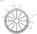
- whole part of the side surface 23 of the second annular portion on the spirally wound body side may form a depression 25 as shown in Fig. 8 .
- depressions 25 may be formed of parts of arcs of two or more concentric circles having the same sectional shape.
- the sectional shape of each depression 25 appearing when the second annular portion 20 is sectionally cut by a plane including the central axis of the anti-telescoping plate 9 is uniform independently of the plane.
- this is a preferable shape for exhibiting the effects of the present invention.
- each depression 25 made on the side surface 23 of the second annular portion on the spirally wound body side may be a through hole penetrating the second annular portion 20.
- the depression 25 is a depression.
- the upper limit of the depth of the depression 25 is preferably a depth within a range of not being a through hole, and preferably smaller than the thickness of the second annular portion 20 of the anti-telescoping plate 9.
- the number of depressions for preventing the rotation is preferably one or more.
- the total volume of the depressions 25 is preferably 0.05% or more and more preferably 0.5% or more of the total volume of the second annular portion 20 in order to exhibit the effect of suppressing the rotation.
- the total volume of the depressions 25 increases, the amount of epoxy resin required for forming the outer shell increases. It is therefore preferable that the total volume of the depressions 25 is about less than 5% of the total volume of the second annular portion 20.
- Fig. 10 is a more preferable sectional shape in vicinities of a part where the water collection tube 1 and the anti-telescoping plate 9 are in contact with each other.
- a structure that depressions 26 are provided in a part on the water collection tube 1 where the anti-telescoping plate 9 and the water collection tube 1 are in contact with each other is more preferable.
- the depressions 26 may be provided in a part on the anti-telescoping plate 9 where the anti-telescoping plate 9 and the water collection tube 1 are in contact with each other.
- the water collection tube 1 and the anti-telescoping plate 9 are bonded to each other through a bonding agent, and the bonding agent entering into the depressions of the water collection tube is hardened so that the anti-telescoping plate 9 can be suppressed from rotating relatively to the water collection tube 1.
- a total of 12 depressions 25 were provided, with intervals of 30 degrees, on a side surface 23 of a second annular portion on a spirally wound body side in each anti-telescoping plate 9.
- Each depression 25 had a diameter of 4 mm and a depth of 2 mm, and the total volume of the depressions 25 was 339 mm 3 , which occupied 0.5% of the total volume of the second annular portion 20.
- a fluid separation element was manufactured using the aforementioned anti-telescoping plates.
- the fluid separation element had a structure in which an outer shell 11 including FRP was provided on the outer circumference of a spirally wound body 17 in which a first separation membrane 3, a second separation membrane 4, a permeate channel material 5 and a raw water channel material 6 were spirally wound, while the anti-telescoping plates 9 were disposed in the both end portions of the spirally wound body 17 and the outer shell 11.
- Fig. 4 is a schematic view showing a form of an envelope-like membrane for use in the spiral type fluid separation element according to the present invention.
- the envelope-like membrane used in the spirally wound body 17 has a combination of the first separation membrane 3 and the second separation membrane 4 so that the first separation membrane 3 is 40 mm shorter than the second separation membrane 4, as shown in Fig. 4 .
- a bonding agent used for bonding the first separation membrane 3 and the second separation membrane 4 leaks wholly or partially from an outer circumferential bonding portion 14 of the envelope-like membrane.
- outer circumferential end portions 13 in the envelope-like membranes adjacent to each other are wholly or partially fixed to each other through the bonding agent.
- the bonding agent is in contact with only the other part than the effective membrane portion 12 of the first separation membrane 3 and the second separation membrane 4.
- the area of the effective membrane portion 12 is 0.7 m 2 or more.
- a test water flow test was performed using the aforementioned fluid separation element.
- One fluid separation element was loaded in a pressure vessel, and operated for five days at five hours per day.
- a rotation angle of the outer shell relative to the anti-telescoping plates was measured after the 5-days operation.
- the rotation angle was 0 degree.
- a fluid separation element was manufactured using anti-telescoping plates each having no depression on a surface (a side surface of a second annular portion on the spirally wound body side) in contact with an end surface of an outer shell.
- the fluid separation element had a structure in which an outer shell 11 including FRP was provided on the outer circumference of a spirally wound body 17 in which a first separation membrane 3, a second separation membrane 4, a permeate channel material 5 and a raw water channel material 6 were spirally wound, while the anti-telescoping plates 9 were disposed in the both end portions of the spirally wound body 17 and the outer shell 11.
- a test water flow test was performed using the aforementioned fluid separation element.
- One fluid separation element was loaded in a pressure vessel, and operated for five days at five hours per day.
- a rotation angle of the outer shell relative to the anti-telescoping plates was measured after the 5-days operation.
- the rotation angle was 1.2 degrees.
Landscapes
- Chemical & Material Sciences (AREA)
- Chemical Kinetics & Catalysis (AREA)
- Life Sciences & Earth Sciences (AREA)
- Hydrology & Water Resources (AREA)
- Engineering & Computer Science (AREA)
- Environmental & Geological Engineering (AREA)
- Water Supply & Treatment (AREA)
- Organic Chemistry (AREA)
- Separation Using Semi-Permeable Membranes (AREA)
Claims (6)
- Teleskopische Präventionsplatte (9), die konfiguriert ist, um an einem von beiden Endbereichen eines spiralförmig gewickelten Körpers (17) und einer äußeren Hülle (11) eines Fluidtrennelements bereitgestellt zu werden, wobei das Fluidtrennelement eine axiale Richtung aufweist und Folgendes umfasst:den spiralförmig gewickelten Körper (17), der eine Trennmembran (3, 4) und ein Rohwasserkanalmaterial (6) umfasst, die spiralförmig um ein Wassersammelrohr (1) gewickelt sind;die äußere Hülle (11), die an einem Außenumfang des spiralförmig gewickelten Körpers (17) bereitgestellt ist; unddie teleskopische Präventionsplatte (9),wobei die teleskopische Präventionsplatte (9) mindestens einen ersten ringförmigen Abschnitt (19), der die äußere Hülle (11) halten kann, und einen zweiten ringförmigen Abschnitt (20) einschließt, der an einer axial äußeren Seite des ersten ringförmigen Abschnitts (19) ausgebildet ist, in dem ein äußerer Endbereich der äußeren Hülle (11) darin verriegelt werden kann, und der eine ringförmige Form mit einem größeren Außendurchmesser als ein Außendurchmesser des ersten ringförmigen Abschnitts (19) aufweist,wobei der erste und der zweite ringförmige Abschnitt (19, 20) Seitenflächen an der axial inneren und axial äußeren Seite aufweisen, wobei die axial innere und axial äußere Seite die Seitenflächen an der Seite des spiralförmig gewickelten Körpers beziehungsweise der dazu gegenüberliegenden Seite sind,wobei die teleskopische Präventionsplatte (9) mindestens eine Vertiefung (25) aufweist, die an einer axial inneren Seitenfläche (23) des zweiten ringförmigen Abschnitts (20) bereitgestellt ist,wobei ein Teil der äußeren Hülle (11) in die mindestens eine Vertiefung (25) eintreten kann, um zu verhindern, dass sich die äußere Hülle (11) relativ zu jeder der teleskopischen Präventionsplatten dreht, wenn das Fluidtrennelement zusammengebaut wird, undwobei Schnittformen oder Positionen der Vertiefung (25), die erscheinen, wenn der zweite ringförmige Abschnitt (20) durch beliebige Ebenen, die durch die Mittelachse der teleskopischen Präventionsplatte (9) verlaufen, abschnittsweise geschnitten wird, sich in Abhängigkeit von den Ebenen in einer Umfangsrichtung des zweiten ringförmigen Abschnitts unterscheiden.
- Teleskopische Präventionsplatte (9) gemäß Anspruch 1, ferner umfassend einen dritten ringförmigen Abschnitt (18), der auf einer axial inneren Seite des ersten ringförmigen Abschnitts (19) ausgebildet ist und eine ringförmige Form mit einem größeren Außendurchmesser als der Außendurchmesser des ersten ringförmigen Abschnitts (19) aufweist.
- Teleskopische Präventionsplatte (9) gemäß einem der Ansprüche 1 oder 2, ferner umfassend einen vierten ringförmigen Abschnitt (21), der auf einer axial äußeren Seite des zweiten ringförmigen Abschnitts (20) ausgebildet ist und in den eine Soledichtung (10) extern eingesetzt werden kann, und einen fünften ringförmigen Abschnitt (22), der auf einer axial äußeren Seite des vierten ringförmigen Abschnitts (21) ausgebildet ist und eine ringförmige Form mit einem größeren Außendurchmesser als ein Außendurchmesser des vierten ringförmigen Abschnitts (21) aufweist, wobei die axial äußere Seite des vierten ringförmigen Abschnitts (21) eine Seitenfläche gegenüber einer spiralförmig gewickelten Körperseite ist.
- Fluidtrennelement mit einer axialen Richtung, wobei das Fluidtrennelement umfasst:einen spiralförmig gewickelten Körper (17), der eine Trennmembran (3, 4) und ein Rohwasserkanalmaterial (6) umfasst, die spiralförmig um ein Wassersammelrohr (1) gewickelt sind;eine äußere Hülle (11), die auf einem Außenumfang des spiralförmig gewickelten Körpers (17) bereitgestellt ist; undteleskopische Präventionsplatten (9), die an beiden Endabschnitten des spiralförmig gewickelten Körpers (17) und der äußeren Hülle (11) bereitgestellt sind,wobei jede der teleskopischen Präventionsplatten (9) mindestens einen ersten ringförmigen Abschnitt (19), der die äußere Hülle (11) halten kann, und einen zweiten ringförmigen Abschnitt (20) einschließt, der auf einer axial äußeren Seite des ersten ringförmigen Abschnitts (19) ausgebildet ist, in dem ein äußerer Endabschnitt der äußeren Hülle (11) darin verriegelt werden kann, und der eine ringförmige Form mit einem größeren Außendurchmesser als ein Außendurchmesser des ersten ringförmigen Abschnitts (19) aufweist,wobei der erste und der zweite ringförmige Abschnitt (19, 20) Seitenflächen auf der axial inneren und axial äußeren Seite aufweisen, wobei die axial innere und axial äußere Seite die Seitenflächen auf der spiralförmig gewickelten Körperseite beziehungsweise der dazu gegenüberliegenden Seite sind,jede der teleskopischen Präventionsplatten (9) mindestens eine Vertiefung (25) aufweist, die auf einer axial inneren Seitenfläche (23) des zweiten ringförmigen Abschnitts (20) vorgesehen ist,wobei ein Teil der äußeren Hülle (11) in die mindestens eine Vertiefung (25) eintritt, um zu verhindern, dass sich die äußere Hülle (11) relativ zu jeder der teleskopischen Präventionsplatten dreht, undwobei Schnittformen oder Positionen der Vertiefung (25), die erscheinen, wenn der zweite ringförmige Abschnitt (20) abschnittsweise durch beliebige Ebenen geschnitten wird, die durch die Mittelachse einer entsprechenden der teleskopischen Präventionsplatten (9) verlaufen, sich abhängig von den Ebenen in einer Umfangsrichtung des zweiten ringförmigen Abschnitts (20) unterscheiden.
- Fluidtrennelement gemäß Anspruch 4, wobei jede der teleskopischen Präventionsplatten (9) ferner einen dritten ringförmigen Abschnitt (18) einschließt, der auf einer axial inneren Seite des ersten ringförmigen Abschnitts (19) ausgebildet ist und eine ringförmige Form mit einem größeren Außendurchmesser als der Außendurchmesser des ersten ringförmigen Abschnitts (19) aufweist.
- Fluidtrennelement gemäß einem der Ansprüche 4 bis 5, wobei jede der teleskopischen Präventionsplatten ferner einen vierten ringförmigen Abschnitt (21), der auf einer axial äußeren Seite des zweiten ringförmigen Abschnitts (20) ausgebildet ist und in den eine Soledichtung (10) extern eingesetzt werden kann, und einen fünften ringförmigen Abschnitt (22) einschließt, der auf einer axial äußeren Seite des vierten ringförmigen Abschnitts (21) ausgebildet ist und eine ringförmige Form mit einem größeren Außendurchmesser als ein Außendurchmesser des vierten ringförmigen Abschnitts (21) aufweist, wobei die axial äußere Seite des vierten ringförmigen Abschnitts (21) eine Seitenfläche gegenüber einer spiralförmig gewickelten Körperseite ist.
Applications Claiming Priority (2)
| Application Number | Priority Date | Filing Date | Title |
|---|---|---|---|
| JP2017070202 | 2017-03-31 | ||
| PCT/JP2018/012614 WO2018181411A1 (ja) | 2017-03-31 | 2018-03-27 | 流体分離素子およびテレスコープ防止板 |
Publications (3)
| Publication Number | Publication Date |
|---|---|
| EP3603775A1 EP3603775A1 (de) | 2020-02-05 |
| EP3603775A4 EP3603775A4 (de) | 2020-05-06 |
| EP3603775B1 true EP3603775B1 (de) | 2024-11-06 |
Family
ID=63677944
Family Applications (1)
| Application Number | Title | Priority Date | Filing Date |
|---|---|---|---|
| EP18778151.3A Active EP3603775B1 (de) | 2017-03-31 | 2018-03-27 | Fluidtrennelement und teleskopische präventionsplatte |
Country Status (6)
| Country | Link |
|---|---|
| US (1) | US11097224B2 (de) |
| EP (1) | EP3603775B1 (de) |
| JP (1) | JP6624285B2 (de) |
| KR (1) | KR102317101B1 (de) |
| CN (1) | CN110505912B (de) |
| WO (1) | WO2018181411A1 (de) |
Families Citing this family (2)
| Publication number | Priority date | Publication date | Assignee | Title |
|---|---|---|---|---|
| KR102719293B1 (ko) * | 2018-09-26 | 2024-10-21 | 도레이 카부시키가이샤 | 유체 분리 소자 |
| US20260001040A1 (en) * | 2022-09-15 | 2026-01-01 | Nitto Denko Corporation | Spiral membrane element and end member for spiral membrane element |
Family Cites Families (14)
| Publication number | Priority date | Publication date | Assignee | Title |
|---|---|---|---|---|
| JPS5219547A (en) | 1975-08-07 | 1977-02-14 | Furukawa Electric Co Ltd:The | Method of connecting together optical fibers |
| JPS5924101U (ja) * | 1982-08-03 | 1984-02-15 | 日東電工株式会社 | 流体分離装置 |
| DE69927312T2 (de) * | 1998-03-20 | 2006-05-11 | Toray Industries, Inc. | Trennelemente für Fluide |
| DK174233B1 (da) * | 2000-12-27 | 2002-10-07 | Dss Danish Separation Systems | Sanitært spiralfilteranlæg |
| US7198719B2 (en) * | 2004-09-03 | 2007-04-03 | Nitto Denko Corporation | Sealer holding member for membrane element and membrane element using the same |
| KR100955443B1 (ko) | 2005-12-22 | 2010-05-04 | 닛토덴코 가부시키가이샤 | 스파이럴형 막 모듈 |
| WO2010090251A1 (ja) | 2009-02-06 | 2010-08-12 | 東レ株式会社 | 流体分離素子、流体分離素子用テレスコープ防止板、及び流体分離装置 |
| JP5401120B2 (ja) * | 2009-02-23 | 2014-01-29 | 日東電工株式会社 | 膜エレメント用端部部材及びこれを備えた膜エレメント |
| JP5287789B2 (ja) | 2010-05-10 | 2013-09-11 | 東レ株式会社 | 流体分離素子及び流体分離装置 |
| US20120132579A1 (en) | 2010-11-30 | 2012-05-31 | Jeffrey Ronald Cumin | Membrane filter assembly and permeate connector |
| JP2012183464A (ja) * | 2011-03-04 | 2012-09-27 | Toray Ind Inc | 流体分離素子用テレスコープ防止板および流体分離素子 |
| ES2912110T3 (es) * | 2011-09-02 | 2022-05-24 | Nanoh2O Inc | Dispositivo de separación de membranas con placa de sellado |
| US20160038881A1 (en) * | 2014-08-05 | 2016-02-11 | Wei-Cheng Yang | Tube assembly for a reverse osmosis filter cartridge |
| CN106555534A (zh) | 2015-09-30 | 2017-04-05 | 德昌电机(深圳)有限公司 | 驱动机构、车窗驱动机构及使用该车窗驱动机构的车辆 |
-
2018
- 2018-03-27 US US16/498,820 patent/US11097224B2/en active Active
- 2018-03-27 KR KR1020197028268A patent/KR102317101B1/ko active Active
- 2018-03-27 WO PCT/JP2018/012614 patent/WO2018181411A1/ja not_active Ceased
- 2018-03-27 CN CN201880021496.7A patent/CN110505912B/zh active Active
- 2018-03-27 EP EP18778151.3A patent/EP3603775B1/de active Active
- 2018-03-27 JP JP2018519079A patent/JP6624285B2/ja active Active
Also Published As
| Publication number | Publication date |
|---|---|
| EP3603775A4 (de) | 2020-05-06 |
| US11097224B2 (en) | 2021-08-24 |
| JPWO2018181411A1 (ja) | 2019-11-07 |
| KR20190130580A (ko) | 2019-11-22 |
| CN110505912A (zh) | 2019-11-26 |
| US20210101118A1 (en) | 2021-04-08 |
| KR102317101B1 (ko) | 2021-10-22 |
| JP6624285B2 (ja) | 2019-12-25 |
| CN110505912B (zh) | 2021-11-26 |
| EP3603775A1 (de) | 2020-02-05 |
| WO2018181411A1 (ja) | 2018-10-04 |
Similar Documents
| Publication | Publication Date | Title |
|---|---|---|
| ES2777829T3 (es) | Ensamblaje de filtro que incluye módulo de membrana en espiral y sello de salmuera | |
| EP2467200B1 (de) | Kontaktor mit hochdruck-flüssigentgasungsmembranen | |
| KR101593341B1 (ko) | 스파이럴형 분리막 엘리먼트용 단부재, 스파이럴형 분리막 엘리먼트 및 분리막 모듈 | |
| US7635428B2 (en) | Hollow fiber membrane submodule and module including the same | |
| EP0055839A1 (de) | Hohlfasermembran-Trennvorrichtung für Fluide | |
| WO2004069391A1 (ja) | 中空糸膜モジュールおよびそのモジュール配列群 | |
| US9975090B2 (en) | Double pass reverse osmosis separator module | |
| CN107530631B (zh) | 包含定位在独立的压力容器中的螺旋卷绕生物反应器和膜模块的过滤总成 | |
| US20190388839A1 (en) | Spiral wound membrane rolls and modules | |
| US11097224B2 (en) | Fluid separating element and telescoping prevention plate | |
| US20150290589A1 (en) | Encapsulating outer shell for membrane elements | |
| JP5287789B2 (ja) | 流体分離素子及び流体分離装置 | |
| JP2015150545A (ja) | スパイラル型流体分離素子 | |
| JP6264938B2 (ja) | 中空糸膜モジュール | |
| JPH11300173A (ja) | 中空糸膜モジュール | |
| JP2015226864A (ja) | 正浸透用中空糸膜モジュール | |
| US12337282B2 (en) | Potted flat sheet membrane filtration module | |
| JP2012183464A (ja) | 流体分離素子用テレスコープ防止板および流体分離素子 | |
| KR101902458B1 (ko) | 중공사막 모듈 | |
| JP2015089536A (ja) | 分離膜エレメントおよび分離膜モジュール | |
| JP6607336B1 (ja) | 分離膜モジュール | |
| JP2011152538A (ja) | 流体分離素子及び流体分離装置 | |
| JP5181917B2 (ja) | スパイラル型流体分離素子 | |
| US12201946B2 (en) | Fluid separation element | |
| JP2011152538A5 (de) |
Legal Events
| Date | Code | Title | Description |
|---|---|---|---|
| STAA | Information on the status of an ep patent application or granted ep patent |
Free format text: STATUS: THE INTERNATIONAL PUBLICATION HAS BEEN MADE |
|
| PUAI | Public reference made under article 153(3) epc to a published international application that has entered the european phase |
Free format text: ORIGINAL CODE: 0009012 |
|
| STAA | Information on the status of an ep patent application or granted ep patent |
Free format text: STATUS: REQUEST FOR EXAMINATION WAS MADE |
|
| 17P | Request for examination filed |
Effective date: 20190926 |
|
| AK | Designated contracting states |
Kind code of ref document: A1 Designated state(s): AL AT BE BG CH CY CZ DE DK EE ES FI FR GB GR HR HU IE IS IT LI LT LU LV MC MK MT NL NO PL PT RO RS SE SI SK SM TR |
|
| AX | Request for extension of the european patent |
Extension state: BA ME |
|
| A4 | Supplementary search report drawn up and despatched |
Effective date: 20200402 |
|
| RIC1 | Information provided on ipc code assigned before grant |
Ipc: B01D 63/00 20060101ALI20200328BHEP Ipc: B01D 63/10 20060101AFI20200328BHEP |
|
| DAV | Request for validation of the european patent (deleted) | ||
| DAX | Request for extension of the european patent (deleted) | ||
| STAA | Information on the status of an ep patent application or granted ep patent |
Free format text: STATUS: EXAMINATION IS IN PROGRESS |
|
| 17Q | First examination report despatched |
Effective date: 20230411 |
|
| GRAP | Despatch of communication of intention to grant a patent |
Free format text: ORIGINAL CODE: EPIDOSNIGR1 |
|
| STAA | Information on the status of an ep patent application or granted ep patent |
Free format text: STATUS: GRANT OF PATENT IS INTENDED |
|
| INTG | Intention to grant announced |
Effective date: 20240611 |
|
| GRAS | Grant fee paid |
Free format text: ORIGINAL CODE: EPIDOSNIGR3 |
|
| GRAA | (expected) grant |
Free format text: ORIGINAL CODE: 0009210 |
|
| STAA | Information on the status of an ep patent application or granted ep patent |
Free format text: STATUS: THE PATENT HAS BEEN GRANTED |
|
| AK | Designated contracting states |
Kind code of ref document: B1 Designated state(s): AL AT BE BG CH CY CZ DE DK EE ES FI FR GB GR HR HU IE IS IT LI LT LU LV MC MK MT NL NO PL PT RO RS SE SI SK SM TR |
|
| REG | Reference to a national code |
Ref country code: GB Ref legal event code: FG4D |
|
| REG | Reference to a national code |
Ref country code: CH Ref legal event code: EP |
|
| REG | Reference to a national code |
Ref country code: DE Ref legal event code: R096 Ref document number: 602018076295 Country of ref document: DE |
|
| P01 | Opt-out of the competence of the unified patent court (upc) registered |
Free format text: CASE NUMBER: APP_58929/2024 Effective date: 20241029 |
|
| REG | Reference to a national code |
Ref country code: IE Ref legal event code: FG4D |
|
| REG | Reference to a national code |
Ref country code: LT Ref legal event code: MG9D |
|
| REG | Reference to a national code |
Ref country code: NL Ref legal event code: MP Effective date: 20241106 |
|
| PG25 | Lapsed in a contracting state [announced via postgrant information from national office to epo] |
Ref country code: HR Free format text: LAPSE BECAUSE OF FAILURE TO SUBMIT A TRANSLATION OF THE DESCRIPTION OR TO PAY THE FEE WITHIN THE PRESCRIBED TIME-LIMIT Effective date: 20241106 Ref country code: PT Free format text: LAPSE BECAUSE OF FAILURE TO SUBMIT A TRANSLATION OF THE DESCRIPTION OR TO PAY THE FEE WITHIN THE PRESCRIBED TIME-LIMIT Effective date: 20250306 Ref country code: IS Free format text: LAPSE BECAUSE OF FAILURE TO SUBMIT A TRANSLATION OF THE DESCRIPTION OR TO PAY THE FEE WITHIN THE PRESCRIBED TIME-LIMIT Effective date: 20250306 |
|
| PG25 | Lapsed in a contracting state [announced via postgrant information from national office to epo] |
Ref country code: NL Free format text: LAPSE BECAUSE OF FAILURE TO SUBMIT A TRANSLATION OF THE DESCRIPTION OR TO PAY THE FEE WITHIN THE PRESCRIBED TIME-LIMIT Effective date: 20241106 Ref country code: FI Free format text: LAPSE BECAUSE OF FAILURE TO SUBMIT A TRANSLATION OF THE DESCRIPTION OR TO PAY THE FEE WITHIN THE PRESCRIBED TIME-LIMIT Effective date: 20241106 |
|
| REG | Reference to a national code |
Ref country code: AT Ref legal event code: MK05 Ref document number: 1738761 Country of ref document: AT Kind code of ref document: T Effective date: 20241106 |
|
| PG25 | Lapsed in a contracting state [announced via postgrant information from national office to epo] |
Ref country code: BG Free format text: LAPSE BECAUSE OF FAILURE TO SUBMIT A TRANSLATION OF THE DESCRIPTION OR TO PAY THE FEE WITHIN THE PRESCRIBED TIME-LIMIT Effective date: 20241106 |
|
| PG25 | Lapsed in a contracting state [announced via postgrant information from national office to epo] |
Ref country code: ES Free format text: LAPSE BECAUSE OF FAILURE TO SUBMIT A TRANSLATION OF THE DESCRIPTION OR TO PAY THE FEE WITHIN THE PRESCRIBED TIME-LIMIT Effective date: 20241106 |
|
| PG25 | Lapsed in a contracting state [announced via postgrant information from national office to epo] |
Ref country code: NO Free format text: LAPSE BECAUSE OF FAILURE TO SUBMIT A TRANSLATION OF THE DESCRIPTION OR TO PAY THE FEE WITHIN THE PRESCRIBED TIME-LIMIT Effective date: 20250206 |
|
| PG25 | Lapsed in a contracting state [announced via postgrant information from national office to epo] |
Ref country code: LV Free format text: LAPSE BECAUSE OF FAILURE TO SUBMIT A TRANSLATION OF THE DESCRIPTION OR TO PAY THE FEE WITHIN THE PRESCRIBED TIME-LIMIT Effective date: 20241106 Ref country code: GR Free format text: LAPSE BECAUSE OF FAILURE TO SUBMIT A TRANSLATION OF THE DESCRIPTION OR TO PAY THE FEE WITHIN THE PRESCRIBED TIME-LIMIT Effective date: 20250207 Ref country code: AT Free format text: LAPSE BECAUSE OF FAILURE TO SUBMIT A TRANSLATION OF THE DESCRIPTION OR TO PAY THE FEE WITHIN THE PRESCRIBED TIME-LIMIT Effective date: 20241106 |
|
| PG25 | Lapsed in a contracting state [announced via postgrant information from national office to epo] |
Ref country code: PL Free format text: LAPSE BECAUSE OF FAILURE TO SUBMIT A TRANSLATION OF THE DESCRIPTION OR TO PAY THE FEE WITHIN THE PRESCRIBED TIME-LIMIT Effective date: 20241106 |
|
| PG25 | Lapsed in a contracting state [announced via postgrant information from national office to epo] |
Ref country code: RS Free format text: LAPSE BECAUSE OF FAILURE TO SUBMIT A TRANSLATION OF THE DESCRIPTION OR TO PAY THE FEE WITHIN THE PRESCRIBED TIME-LIMIT Effective date: 20250206 |
|
| PG25 | Lapsed in a contracting state [announced via postgrant information from national office to epo] |
Ref country code: SM Free format text: LAPSE BECAUSE OF FAILURE TO SUBMIT A TRANSLATION OF THE DESCRIPTION OR TO PAY THE FEE WITHIN THE PRESCRIBED TIME-LIMIT Effective date: 20241106 |
|
| PG25 | Lapsed in a contracting state [announced via postgrant information from national office to epo] |
Ref country code: DK Free format text: LAPSE BECAUSE OF FAILURE TO SUBMIT A TRANSLATION OF THE DESCRIPTION OR TO PAY THE FEE WITHIN THE PRESCRIBED TIME-LIMIT Effective date: 20241106 |
|
| PG25 | Lapsed in a contracting state [announced via postgrant information from national office to epo] |
Ref country code: EE Free format text: LAPSE BECAUSE OF FAILURE TO SUBMIT A TRANSLATION OF THE DESCRIPTION OR TO PAY THE FEE WITHIN THE PRESCRIBED TIME-LIMIT Effective date: 20241106 |
|
| PG25 | Lapsed in a contracting state [announced via postgrant information from national office to epo] |
Ref country code: RO Free format text: LAPSE BECAUSE OF FAILURE TO SUBMIT A TRANSLATION OF THE DESCRIPTION OR TO PAY THE FEE WITHIN THE PRESCRIBED TIME-LIMIT Effective date: 20241106 |
|
| PG25 | Lapsed in a contracting state [announced via postgrant information from national office to epo] |
Ref country code: SK Free format text: LAPSE BECAUSE OF FAILURE TO SUBMIT A TRANSLATION OF THE DESCRIPTION OR TO PAY THE FEE WITHIN THE PRESCRIBED TIME-LIMIT Effective date: 20241106 |
|
| PG25 | Lapsed in a contracting state [announced via postgrant information from national office to epo] |
Ref country code: CZ Free format text: LAPSE BECAUSE OF FAILURE TO SUBMIT A TRANSLATION OF THE DESCRIPTION OR TO PAY THE FEE WITHIN THE PRESCRIBED TIME-LIMIT Effective date: 20241106 |
|
| PG25 | Lapsed in a contracting state [announced via postgrant information from national office to epo] |
Ref country code: IT Free format text: LAPSE BECAUSE OF FAILURE TO SUBMIT A TRANSLATION OF THE DESCRIPTION OR TO PAY THE FEE WITHIN THE PRESCRIBED TIME-LIMIT Effective date: 20241106 |
|
| REG | Reference to a national code |
Ref country code: DE Ref legal event code: R097 Ref document number: 602018076295 Country of ref document: DE |
|
| PG25 | Lapsed in a contracting state [announced via postgrant information from national office to epo] |
Ref country code: SE Free format text: LAPSE BECAUSE OF FAILURE TO SUBMIT A TRANSLATION OF THE DESCRIPTION OR TO PAY THE FEE WITHIN THE PRESCRIBED TIME-LIMIT Effective date: 20241106 |
|
| PLBE | No opposition filed within time limit |
Free format text: ORIGINAL CODE: 0009261 |
|
| STAA | Information on the status of an ep patent application or granted ep patent |
Free format text: STATUS: NO OPPOSITION FILED WITHIN TIME LIMIT |
|
| PG25 | Lapsed in a contracting state [announced via postgrant information from national office to epo] |
Ref country code: MC Free format text: LAPSE BECAUSE OF FAILURE TO SUBMIT A TRANSLATION OF THE DESCRIPTION OR TO PAY THE FEE WITHIN THE PRESCRIBED TIME-LIMIT Effective date: 20241106 |
|
| 26N | No opposition filed |
Effective date: 20250807 |
|
| REG | Reference to a national code |
Ref country code: CH Ref legal event code: H13 Free format text: ST27 STATUS EVENT CODE: U-0-0-H10-H13 (AS PROVIDED BY THE NATIONAL OFFICE) Effective date: 20251024 |
|
| PG25 | Lapsed in a contracting state [announced via postgrant information from national office to epo] |
Ref country code: LU Free format text: LAPSE BECAUSE OF NON-PAYMENT OF DUE FEES Effective date: 20250327 |
|
| GBPC | Gb: european patent ceased through non-payment of renewal fee |
Effective date: 20250327 |
|
| REG | Reference to a national code |
Ref country code: BE Ref legal event code: MM Effective date: 20250331 |
|
| PG25 | Lapsed in a contracting state [announced via postgrant information from national office to epo] |
Ref country code: GB Free format text: LAPSE BECAUSE OF NON-PAYMENT OF DUE FEES Effective date: 20250327 |
|
| PG25 | Lapsed in a contracting state [announced via postgrant information from national office to epo] |
Ref country code: FR Free format text: LAPSE BECAUSE OF NON-PAYMENT OF DUE FEES Effective date: 20250331 |
|
| PG25 | Lapsed in a contracting state [announced via postgrant information from national office to epo] |
Ref country code: BE Free format text: LAPSE BECAUSE OF NON-PAYMENT OF DUE FEES Effective date: 20250331 |
|
| PG25 | Lapsed in a contracting state [announced via postgrant information from national office to epo] |
Ref country code: CH Free format text: LAPSE BECAUSE OF NON-PAYMENT OF DUE FEES Effective date: 20250331 |
|
| PG25 | Lapsed in a contracting state [announced via postgrant information from national office to epo] |
Ref country code: IE Free format text: LAPSE BECAUSE OF NON-PAYMENT OF DUE FEES Effective date: 20250327 |
|
| PGFP | Annual fee paid to national office [announced via postgrant information from national office to epo] |
Ref country code: DE Payment date: 20260128 Year of fee payment: 9 |