EP3603493B1 - Unipolare referenzelektrode für einen elektrophysiologieabbildungskatheter - Google Patents
Unipolare referenzelektrode für einen elektrophysiologieabbildungskatheter Download PDFInfo
- Publication number
- EP3603493B1 EP3603493B1 EP19189827.9A EP19189827A EP3603493B1 EP 3603493 B1 EP3603493 B1 EP 3603493B1 EP 19189827 A EP19189827 A EP 19189827A EP 3603493 B1 EP3603493 B1 EP 3603493B1
- Authority
- EP
- European Patent Office
- Prior art keywords
- arms
- ring electrode
- end effector
- electrode
- tissue
- Prior art date
- Legal status (The legal status is an assumption and is not a legal conclusion. Google has not performed a legal analysis and makes no representation as to the accuracy of the status listed.)
- Active
Links
Images


Classifications
-
- A—HUMAN NECESSITIES
- A61—MEDICAL OR VETERINARY SCIENCE; HYGIENE
- A61B—DIAGNOSIS; SURGERY; IDENTIFICATION
- A61B18/00—Surgical instruments, devices or methods for transferring non-mechanical forms of energy to or from the body
- A61B18/04—Surgical instruments, devices or methods for transferring non-mechanical forms of energy to or from the body by heating
- A61B18/12—Surgical instruments, devices or methods for transferring non-mechanical forms of energy to or from the body by heating by passing a current through the tissue to be heated, e.g. high-frequency current
- A61B18/1206—Generators therefor
-
- A—HUMAN NECESSITIES
- A61—MEDICAL OR VETERINARY SCIENCE; HYGIENE
- A61B—DIAGNOSIS; SURGERY; IDENTIFICATION
- A61B18/00—Surgical instruments, devices or methods for transferring non-mechanical forms of energy to or from the body
- A61B18/04—Surgical instruments, devices or methods for transferring non-mechanical forms of energy to or from the body by heating
- A61B18/12—Surgical instruments, devices or methods for transferring non-mechanical forms of energy to or from the body by heating by passing a current through the tissue to be heated, e.g. high-frequency current
- A61B18/14—Probes or electrodes therefor
- A61B18/1492—Probes or electrodes therefor having a flexible, catheter-like structure, e.g. for heart ablation
-
- A—HUMAN NECESSITIES
- A61—MEDICAL OR VETERINARY SCIENCE; HYGIENE
- A61B—DIAGNOSIS; SURGERY; IDENTIFICATION
- A61B18/00—Surgical instruments, devices or methods for transferring non-mechanical forms of energy to or from the body
- A61B18/04—Surgical instruments, devices or methods for transferring non-mechanical forms of energy to or from the body by heating
- A61B18/12—Surgical instruments, devices or methods for transferring non-mechanical forms of energy to or from the body by heating by passing a current through the tissue to be heated, e.g. high-frequency current
- A61B18/14—Probes or electrodes therefor
- A61B18/16—Indifferent or passive electrodes for grounding
-
- A—HUMAN NECESSITIES
- A61—MEDICAL OR VETERINARY SCIENCE; HYGIENE
- A61B—DIAGNOSIS; SURGERY; IDENTIFICATION
- A61B5/00—Measuring for diagnostic purposes; Identification of persons
- A61B5/24—Detecting, measuring or recording bioelectric or biomagnetic signals of the body or parts thereof
- A61B5/25—Bioelectric electrodes therefor
- A61B5/279—Bioelectric electrodes therefor specially adapted for particular uses
- A61B5/28—Bioelectric electrodes therefor specially adapted for particular uses for electrocardiography [ECG]
- A61B5/283—Invasive
- A61B5/287—Holders for multiple electrodes, e.g. electrode catheters for electrophysiological study [EPS]
-
- A—HUMAN NECESSITIES
- A61—MEDICAL OR VETERINARY SCIENCE; HYGIENE
- A61B—DIAGNOSIS; SURGERY; IDENTIFICATION
- A61B5/00—Measuring for diagnostic purposes; Identification of persons
- A61B5/68—Arrangements of detecting, measuring or recording means, e.g. sensors, in relation to patient
- A61B5/6846—Arrangements of detecting, measuring or recording means, e.g. sensors, in relation to patient specially adapted to be brought in contact with an internal body part, i.e. invasive
- A61B5/6847—Arrangements of detecting, measuring or recording means, e.g. sensors, in relation to patient specially adapted to be brought in contact with an internal body part, i.e. invasive mounted on an invasive device
- A61B5/6852—Catheters
- A61B5/6858—Catheters with a distal basket, e.g. expandable basket
-
- A—HUMAN NECESSITIES
- A61—MEDICAL OR VETERINARY SCIENCE; HYGIENE
- A61B—DIAGNOSIS; SURGERY; IDENTIFICATION
- A61B5/00—Measuring for diagnostic purposes; Identification of persons
- A61B5/68—Arrangements of detecting, measuring or recording means, e.g. sensors, in relation to patient
- A61B5/6846—Arrangements of detecting, measuring or recording means, e.g. sensors, in relation to patient specially adapted to be brought in contact with an internal body part, i.e. invasive
- A61B5/6847—Arrangements of detecting, measuring or recording means, e.g. sensors, in relation to patient specially adapted to be brought in contact with an internal body part, i.e. invasive mounted on an invasive device
- A61B5/6852—Catheters
- A61B5/6859—Catheters with multiple distal splines
-
- A—HUMAN NECESSITIES
- A61—MEDICAL OR VETERINARY SCIENCE; HYGIENE
- A61B—DIAGNOSIS; SURGERY; IDENTIFICATION
- A61B5/00—Measuring for diagnostic purposes; Identification of persons
- A61B5/68—Arrangements of detecting, measuring or recording means, e.g. sensors, in relation to patient
- A61B5/6846—Arrangements of detecting, measuring or recording means, e.g. sensors, in relation to patient specially adapted to be brought in contact with an internal body part, i.e. invasive
- A61B5/6867—Arrangements of detecting, measuring or recording means, e.g. sensors, in relation to patient specially adapted to be brought in contact with an internal body part, i.e. invasive specially adapted to be attached or implanted in a specific body part
- A61B5/6869—Heart
-
- A—HUMAN NECESSITIES
- A61—MEDICAL OR VETERINARY SCIENCE; HYGIENE
- A61B—DIAGNOSIS; SURGERY; IDENTIFICATION
- A61B18/00—Surgical instruments, devices or methods for transferring non-mechanical forms of energy to or from the body
- A61B2018/00053—Mechanical features of the instrument of device
- A61B2018/0016—Energy applicators arranged in a two- or three dimensional array
-
- A—HUMAN NECESSITIES
- A61—MEDICAL OR VETERINARY SCIENCE; HYGIENE
- A61B—DIAGNOSIS; SURGERY; IDENTIFICATION
- A61B18/00—Surgical instruments, devices or methods for transferring non-mechanical forms of energy to or from the body
- A61B2018/00053—Mechanical features of the instrument of device
- A61B2018/00214—Expandable means emitting energy, e.g. by elements carried thereon
-
- A—HUMAN NECESSITIES
- A61—MEDICAL OR VETERINARY SCIENCE; HYGIENE
- A61B—DIAGNOSIS; SURGERY; IDENTIFICATION
- A61B18/00—Surgical instruments, devices or methods for transferring non-mechanical forms of energy to or from the body
- A61B2018/00315—Surgical instruments, devices or methods for transferring non-mechanical forms of energy to or from the body for treatment of particular body parts
- A61B2018/00345—Vascular system
- A61B2018/00351—Heart
- A61B2018/00357—Endocardium
-
- A—HUMAN NECESSITIES
- A61—MEDICAL OR VETERINARY SCIENCE; HYGIENE
- A61B—DIAGNOSIS; SURGERY; IDENTIFICATION
- A61B18/00—Surgical instruments, devices or methods for transferring non-mechanical forms of energy to or from the body
- A61B2018/00571—Surgical instruments, devices or methods for transferring non-mechanical forms of energy to or from the body for achieving a particular surgical effect
- A61B2018/00577—Ablation
-
- A—HUMAN NECESSITIES
- A61—MEDICAL OR VETERINARY SCIENCE; HYGIENE
- A61B—DIAGNOSIS; SURGERY; IDENTIFICATION
- A61B18/00—Surgical instruments, devices or methods for transferring non-mechanical forms of energy to or from the body
- A61B2018/00571—Surgical instruments, devices or methods for transferring non-mechanical forms of energy to or from the body for achieving a particular surgical effect
- A61B2018/00595—Cauterization
-
- A—HUMAN NECESSITIES
- A61—MEDICAL OR VETERINARY SCIENCE; HYGIENE
- A61B—DIAGNOSIS; SURGERY; IDENTIFICATION
- A61B18/00—Surgical instruments, devices or methods for transferring non-mechanical forms of energy to or from the body
- A61B2018/00636—Sensing and controlling the application of energy
- A61B2018/00773—Sensed parameters
- A61B2018/00839—Bioelectrical parameters, e.g. ECG, EEG
-
- A—HUMAN NECESSITIES
- A61—MEDICAL OR VETERINARY SCIENCE; HYGIENE
- A61B—DIAGNOSIS; SURGERY; IDENTIFICATION
- A61B18/00—Surgical instruments, devices or methods for transferring non-mechanical forms of energy to or from the body
- A61B2018/00636—Sensing and controlling the application of energy
- A61B2018/00773—Sensed parameters
- A61B2018/00875—Resistance or impedance
-
- A—HUMAN NECESSITIES
- A61—MEDICAL OR VETERINARY SCIENCE; HYGIENE
- A61B—DIAGNOSIS; SURGERY; IDENTIFICATION
- A61B18/00—Surgical instruments, devices or methods for transferring non-mechanical forms of energy to or from the body
- A61B18/04—Surgical instruments, devices or methods for transferring non-mechanical forms of energy to or from the body by heating
- A61B18/12—Surgical instruments, devices or methods for transferring non-mechanical forms of energy to or from the body by heating by passing a current through the tissue to be heated, e.g. high-frequency current
- A61B18/1206—Generators therefor
- A61B2018/1246—Generators therefor characterised by the output polarity
- A61B2018/1253—Generators therefor characterised by the output polarity monopolar
-
- A—HUMAN NECESSITIES
- A61—MEDICAL OR VETERINARY SCIENCE; HYGIENE
- A61B—DIAGNOSIS; SURGERY; IDENTIFICATION
- A61B18/00—Surgical instruments, devices or methods for transferring non-mechanical forms of energy to or from the body
- A61B18/04—Surgical instruments, devices or methods for transferring non-mechanical forms of energy to or from the body by heating
- A61B18/12—Surgical instruments, devices or methods for transferring non-mechanical forms of energy to or from the body by heating by passing a current through the tissue to be heated, e.g. high-frequency current
- A61B18/1206—Generators therefor
- A61B2018/1246—Generators therefor characterised by the output polarity
- A61B2018/126—Generators therefor characterised by the output polarity bipolar
-
- A—HUMAN NECESSITIES
- A61—MEDICAL OR VETERINARY SCIENCE; HYGIENE
- A61B—DIAGNOSIS; SURGERY; IDENTIFICATION
- A61B18/00—Surgical instruments, devices or methods for transferring non-mechanical forms of energy to or from the body
- A61B18/04—Surgical instruments, devices or methods for transferring non-mechanical forms of energy to or from the body by heating
- A61B18/12—Surgical instruments, devices or methods for transferring non-mechanical forms of energy to or from the body by heating by passing a current through the tissue to be heated, e.g. high-frequency current
- A61B18/14—Probes or electrodes therefor
- A61B2018/1405—Electrodes having a specific shape
- A61B2018/1407—Loop
-
- A—HUMAN NECESSITIES
- A61—MEDICAL OR VETERINARY SCIENCE; HYGIENE
- A61B—DIAGNOSIS; SURGERY; IDENTIFICATION
- A61B18/00—Surgical instruments, devices or methods for transferring non-mechanical forms of energy to or from the body
- A61B18/04—Surgical instruments, devices or methods for transferring non-mechanical forms of energy to or from the body by heating
- A61B18/12—Surgical instruments, devices or methods for transferring non-mechanical forms of energy to or from the body by heating by passing a current through the tissue to be heated, e.g. high-frequency current
- A61B18/14—Probes or electrodes therefor
- A61B2018/1405—Electrodes having a specific shape
- A61B2018/144—Wire
-
- A—HUMAN NECESSITIES
- A61—MEDICAL OR VETERINARY SCIENCE; HYGIENE
- A61B—DIAGNOSIS; SURGERY; IDENTIFICATION
- A61B18/00—Surgical instruments, devices or methods for transferring non-mechanical forms of energy to or from the body
- A61B18/04—Surgical instruments, devices or methods for transferring non-mechanical forms of energy to or from the body by heating
- A61B18/12—Surgical instruments, devices or methods for transferring non-mechanical forms of energy to or from the body by heating by passing a current through the tissue to be heated, e.g. high-frequency current
- A61B18/14—Probes or electrodes therefor
- A61B2018/1465—Deformable electrodes
-
- A—HUMAN NECESSITIES
- A61—MEDICAL OR VETERINARY SCIENCE; HYGIENE
- A61B—DIAGNOSIS; SURGERY; IDENTIFICATION
- A61B18/00—Surgical instruments, devices or methods for transferring non-mechanical forms of energy to or from the body
- A61B18/04—Surgical instruments, devices or methods for transferring non-mechanical forms of energy to or from the body by heating
- A61B18/12—Surgical instruments, devices or methods for transferring non-mechanical forms of energy to or from the body by heating by passing a current through the tissue to be heated, e.g. high-frequency current
- A61B18/14—Probes or electrodes therefor
- A61B2018/1467—Probes or electrodes therefor using more than two electrodes on a single probe
Definitions
- Cardiac arrhythmias such as atrial fibrillation, occur when regions of cardiac tissue abnormally conduct electric signals. Procedures for treating arrhythmia include surgically disrupting the conducting pathway for such signals.
- energy e.g., radiofrequency (RF) energy
- RF radiofrequency
- a catheter with one or more RF electrodes may be used to provide ablation within the cardiovascular system.
- the catheter may be inserted into a major vein or artery (e.g., the femoral artery) and then advanced to position the electrodes within the heart or in a cardiovascular structure adjacent to the heart (e.g., the pulmonary vein).
- the electrodes may be placed in contact with cardiac tissue or other vascular tissue and then activated with RF energy to thereby ablate the contacted tissue.
- the electrodes may be bipolar.
- a monopolar electrode may be used in conjunction with a ground pad that is in contact with the patient.
- EP mapping may include the use of sensing electrodes on a catheter (e.g., the same catheter that is used to perform the ablation). Such sensing electrodes may monitor electrical signals within the cardiovascular system to pinpoint the location of aberrant conductive tissue sites that are responsible for the arrhythmia. Examples of an EP mapping system are described in U.S. Pat. No. 5,738,096, entitled “Cardiac Electromechanics,” issued April 14, 1998 . Examples of EP mapping catheters are described in U.S. Pat. No. 9,907,480, entitled “Catheter Spine Assembly with Closely-Spaced Bipole Microelectrodes,” issued March 6, 2018 ; U.S. Pub. No.
- 2018/0036078 entitled “Catheter with Soft Distal Tip for Mapping and Ablating Tubular Region,” published February 8, 2018 ; and U.S. Pub. No. 2018/0056038, entitled “Catheter with Bipole Electrode Spacer and Related Methods,” published March 1, 2018 .
- Central shaft (150) of the present example further includes a ring electrode (154), which is configured to serve as a reference electrode as will be described in greater detail below.
- Ring electrode (154) is positioned to contact blood when end effector (130) is located within a cardiovascular structure in a patient (e.g., in the pulmonary vein, etc.).
- arms (140) are also configured to prevent ring electrode (154) from contacting tissue while end effector (130) is disposed in a cardiovascular structure.
- one or more electrodes (146, 148) will contact tissue while ring electrode (154) does not contact tissue.
- the physician (PH) may urge end effector (130) against a tissue surface (T).
- ring electrode (154) While ring electrode (154) does not contact the tissue surface (T), ring electrode (154) will nevertheless contact blood flowing through the cardiovascular system.
- end effector (130) is positioned in the pulmonary vein, for example, one or more electrodes (146, 148) may contact the tissue surface (T) while ring electrode (154) contacts blood flowing through the pulmonary vein.
- the one or more electrodes (146, 148) contacting the tissue surface (T) may pick up electrical potentials at the contacted regions of the tissue surface (T), while ring electrode (154) picks up a reference potential from the blood in which ring electrode (154) is disposed.
- the processor of console (12) may process the potentials from electrodes (146, 148, 154) and thereby provide an electrocardiogram signal.
- Such electrocardiogram signals may be used to provide EP mapping to thereby identify locations of aberrant electrical activity within the cardiac anatomy. This may in turn allow the physician (PH) to identify the most appropriate regions of cardiac tissue to ablate (e.g., with RF energy, cryoablation, etc.), to thereby prevent or at least reduce the communication of aberrant electrical activity across the cardiac tissue.
- PH physician
- ablate e.g., with RF energy, cryoablation, etc.
- FIG. 5 shows an exemplary three-dimensional profile (160) that may be defined by at least proximal portions of arms (140). While arms (140) are omitted from FIG. 5 , it should be understood that at least the proximal portions of arms (140) may be generally arranged around the boundary depicted as three-dimensional profile (160). In some versions, arms (140) are resiliently biased such that at least the proximal portions of arms (140) define three-dimensional profile (160).
- Three-dimensional profile (160) of this example includes a cylindrical portion (162) and a bellmouth-shaped frusto-conical portion (170). Cylindrical portion (162) is proximally bounded by a proximal plane (166) and distally bounded by an intermediate plane (164). Proximal plane (166) is located at distal end (124) of catheter shaft (122). Bellmouth-shaped frusto-conical portion (170) is proximally bounded by intermediate plane (164) and distally bounded by distal plane (17
- distal plane (172) is located at the free ends or distal tips of arms (140), such that arms (140) distally terminate at distal plane (172).
- arms (140) continue to extend distally along respective straight paths at distal plane (172), such that bellmouth-shaped frusto-conical portion (170) represents an intermediate curved portion of each arm (140) that is longitudinally interposed between respective distal and proximal straight portions of each arm (140).
- these respective straight paths are obliquely oriented away from the longitudinal axis (L-L) of catheter shaft (122).
- FIG. 7 depicts just one arm (140) of end effector (130), it being understood that the other arms (140) may be similarly configured (albeit arranged in an angularly spaced array).
- arm (140) includes a first segment (141), a second segment (143), and a third segment (145).
- First segment (141) extends from distal end (124) of shaft (122), from proximal plane (166) to intermediate plane (164).
- First segment (141) is substantially straight and is parallel with the central longitudinal axis (L-L) of shaft (122).
- first segments (141) of the angularly spaced array of arms (140) will generally define a cylindrical portion (162) of a three-dimensional profile (160) as referred to above in the context of FIG. 5 .
- Second segment (143) is distal to first segment (141) and extends from intermediate plane (164) to distal plane (172).
- Second segment (143) extends along a curve, bending away from the central longitudinal axis (L-L) of shaft (122).
- second segments (143) of the angularly spaced array of arms (140) will generally define a bellmouth-shaped frusto-conical portion (170) of a three-dimensional profile (160) as referred to above in the context of FIG. 5 .
- the oblique angle defined between third segment (145) and the central longitudinal axis (L-L) of shaft (122) may be larger than the oblique angle defined between second segment (143) and the central longitudinal axis (L-L) of shaft (122).
- cross-sectional areas (Ap, Ai, Ad) are shown as orthogonal with respect to the longitudinal axis (L-L) in the exemplary figures due to the configuration of arms (140) being symmetric about the longitudinal axis (L-L), the splaying of arms (140) does not necessarily have to be symmetrical with respect to the longitudinal axis (L-L) and therefore the proximal, intermediate and distal planes of the respective areas (Ap, Ai, Ad) may intersect each other or otherwise be non-orthogonal with respect to the longitudinal axis (L-L).
- the flow of blood around ring electrode (154) may be relatively smooth, which may enable ring electrode (154) to pick up electrical potentials from the blood in a relatively reliable fashion.
- the arrangement of arms (140) around ring electrode (154) may affect the flow of blood around electrode (154) such that the flow is less turbulent than the flow otherwise might be if ring electrode (154) were positioned elsewhere; and such that the pickup of electrical potentials from the blood by ring electrode (154) is more reliable than it otherwise might be if ring electrode (154) were positioned elsewhere.
- the reduction in blood flow turbulence, and increase in sensing reliability by ring electrode (154), may be particularly enhanced when ring electrode (154) is enshrouded by cylindrical portion (164).
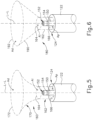
- FIG. 6 shows another exemplary three-dimensional profile (180) that may be defined by at least proximal portions of arms (140). While arms (140) are omitted from FIG. 6 , it should be understood that at least the proximal portions of arms (140) may be generally arranged around the boundary depicted as three-dimensional profile (180). In some versions, arms (140) are resiliently biased such that at least the proximal portions of arms (140) define three-dimensional profile (180).
- Three-dimensional profile (180) of this example includes cylindrical portion (162) and a pyramid-shaped frusto-conical portion (190). Cylindrical portion (162) is proximally bounded by a proximal plane (166) and distally bounded by an intermediate plane (164). Proximal plane (166) is located at distal end (124) of catheter shaft (122). Pyramid-shaped frusto-conical portion (190) is proximally bounded by intermediate plane (164) and distally bounded by distal plane (192).
- distal plane (192) is located at the free ends or distal tips of arms (140), such that arms (140) distally terminate at distal plane (192).
- arms (140) continue to extend distally along respective straight paths at distal plane (192), such that pyramid-shaped frusto-conical portion (190) represents an intermediate angled portion of each arm (140) that is longitudinally interposed between respective distal and proximal straight portions of each arm (140).
- arms (140) extend distally along respective straight paths at distal plane (192), these respective straight paths are obliquely oriented away from the longitudinal axis (L-L) of catheter shaft (122) (e.g., at angles that are larger than the angles represented by pyramid-shaped frusto-conical portion (190). In some other versions where arms (140) extend distally along respective straight paths at distal plane (192), these respective straight paths are parallel with the longitudinal axis (L-L) of catheter shaft (122). In either case, or in other configurations, it should be understood that arms (140) may continue to extend distally past distal plane (192), such that distal plane (192) should not be viewed as necessarily corresponding with the distal end of end effector (130).
- intermediate plane (164) represents the longitudinal position where arms (140) transition from being generally straight and parallel with each other to splaying outwardly away from each other along respective oblique paths.
- the cross-sectional area of the proximal plane (166) region of three-dimensional profile (180) is approximately equal to the cross-sectional area of the intermediate plane (164) region of three-dimensional profile (180).
- the cross-sectional area of the distal plane (192) region is larger than the cross-sectional area of the other planes (164, 166).
- central shaft (150) and ring electrode (154) are configured and positioned such that the longitudinal position of electrode (154) corresponds with cylindrical portion (162) of three-dimensional profile (180). Ring electrode (154) is thus proximally located in relation to intermediate plane (164). Ring electrode (154) may thus be regarded as being enshrouded by cylindrical portion (162) of three-dimensional profile (180) defined by arms (140) of end effector (130).
- central shaft (150) and ring electrode (154) are configured and positioned such that ring electrode (154) is longitudinally positioned between distal plane (192) and intermediate plane (164).
- ring electrode (154) may be regarded as being enshrouded by pyramid-shaped frusto-conical portion (190) of three-dimensional profile (180) defined by arms (140) of end effector (130).
- the flow of blood around ring electrode (154) may be relatively smooth, which may enable ring electrode (154) to pick up electrical potentials from the blood in a relatively reliable fashion.
- the arrangement of arms (140) around ring electrode (154) may affect the flow of blood around electrode (154) such that the flow is less turbulent than the flow otherwise might be if ring electrode (154) were positioned elsewhere; and such that the pickup of electrical potentials from the blood by ring electrode (154) is more reliable than it otherwise might be if ring electrode (154) were positioned elsewhere.
- the reduction in blood flow turbulence, and increase in sensing reliability by ring electrode (154), may be particularly enhanced when ring electrode (154) is enshrouded by cylindrical portion (162).
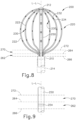
- FIG. 8 shows another exemplary end effector (200) that may be incorporated into catheter assembly (100) in place of end effector (130).
- End effector (200) of this example includes an expandable assembly (220) that is formed by an angularly spaced array of beams (222).
- Each beam (222) includes four pairs (230) of bipolar electrodes (232, 234).
- Electrodes (232, 234) are each generally rectangular and are configured to pick up electrical potentials from tissue, just like electrodes (146, 148) described above. Electrodes (232, 234) may be used in a bipolar fashion or a unipolar fashion. The entirety of each electrode (232, 234) is confined to the outwardly presented surface of each beam (222) in the present example. Beams (222) thus have electrodes (232, 234) on only one side of each beam (222) (i.e., the tissue-contacting side of each beam (222)).
- the proximal ends of beams (222) are positioned in an outer shaft (210), which may be considered as being analogous to catheter shaft (122) described above.
- the distal ends of beams (222) are coupled with a hub member (212).
- Hub member (212) is secured to a central inner shaft (250), which is coaxially positioned at the center of expandable assembly (220).
- Beams (222) are configured to transition expandable assembly (220) between a non-expanded state and an expanded state. The expanded state is shown in FIG. 8 . When expandable assembly (220) is in the non-expanded state, beams (222) are urged inwardly to define an effective outer diameter that is less than or equal to the inner diameter of outer shaft (210).
- beams (222) are resiliently biased to provide expandable assembly (220) in the expanded state.
- an outer sheath (214) is slidably disposed about outer shaft (210).
- sheath (214) constrains beams (222) inwardly, thereby maintaining expandable assembly (220) in the non-expanded state.
- sheath (214) is in a proximal position (e.g., as shown in FIG. 8 , such that the distal end of sheath (214) is proximal to expandable assembly (220))
- beams (222) may resiliently provide expandable assembly (220) in the expanded state.
- the state of expandable assembly (220) may be based on the relative longitudinal positioning of inner shaft (250) and outer shaft (210).
- an actuator on handle (110) may drive outer shaft (210) proximally relative to inner shaft (250) to urge expandable assembly (220) to the non-expanded state; and drive outer shaft (210) distally relative to inner shaft (250) to urge expandable assembly (220) to the expanded state.
- an actuator on handle (110) may drive inner shaft (250) distally relative to outer shaft (210) to urge expandable assembly (220) to the non-expanded state; and drive inner shaft (250) proximally relative to inner shaft (210) to urge expandable assembly (220) to the expanded state.
- Various suitable forms of inputs that may be provided on handle (110) to provide such actuation, as well as various suitable ways in which expandable assembly (220) may transition between the non-expanded state and the expanded state, will be apparent to those skilled in the art in view of the teachings herein.
- end effector (200) may be considered in relation to three planes (264, 266, 272), which are perpendicular to the longitudinal axis (L-L) of shafts (210, 250).
- a proximal plane (266) is located at the distal end of shaft (210) and at the proximal end of end effector (200).
- An intermediate plane (264) is distal to proximal plane (266).
- a distal plane (272) is distal to intermediate plane (264).
- the longitudinal region of end effector (200) between planes (264, 266) may be regarded as a cylindrical portion (262) defining a cylindrical three-dimensional profile, much like cylindrical portion (162) described above in relation to FIGS. 5-6 .
- the portions of beams (222) extending along cylindrical portion (262) may extend along respective straight paths that are parallel with the longitudinal axis (L-L) of shafts (210, 250).
- the longitudinal region of end effector (200) between planes (264, 272) may be regarded as a bellmouth-shaped frusto-conical portion (270) defining a bellmouth-shaped frusto-conical three-dimensional profile, much like bellmouth-shaped frusto-conical portion (170) described above in relation to FIG. 5 .
- the portions of beams (222) extending along bellmouth-shaped frusto-conical portion (270) extend along respective curved paths curving outwardly away from the longitudinal axis (L-L) of shafts (210, 250).
- the portions of beams (222) extending distally from distal plane (272) curve back inwardly toward the longitudinal axis (L-L) of shafts (210, 250), eventually leading to hub member (212).
- Distal plane (272) thus represents a transition of beams (222) from extending outwardly along respective curved paths to extending inwardly along respective curved paths.
- Inner shaft (250) of this example includes a ring electrode (254), which is coaxially disposed about inner shaft (250) as shown in FIG. 9 .
- ring electrode (254) is longitudinally positioned between planes (264, 266), such that the longitudinal position of ring electrode (254) corresponds with the longitudinal position of cylindrical portion (262), and such that ring electrode (254) is enshrouded by cylindrical portion (262).
- ring electrode (254) is longitudinally positioned between planes (264, 272), such that the longitudinal position of ring electrode (254) corresponds with the longitudinal position of bellmouth-shaped frusto-conical portion (270), and such that ring electrode (254) is enshrouded by bellmouth-shaped frusto-conical portion (270).
- Beams (222) are thus configured to prevent tissue from contacting ring electrode (254). Beams (222) nevertheless allow blood to flow through expandable assembly (220), thereby allowing blood to contact ring electrode (254).
- one or more electrodes (232, 234) on beams (222) may contact a tissue surface (T) and thereby pick up electrical potentials at the contacted regions of the tissue surface (T), while ring electrode (254) picks up a reference potential from the blood in which ring electrode (254) is disposed.
- the processor of console (12) may process the potentials from electrodes (232, 234, 254) and thereby provide an electrocardiogram signal as described above.
- the flow of blood around ring electrode (254) may be relatively smooth, which may enable ring electrode (254) to pick up electrical potentials from the blood in a relatively reliable fashion.
- the arrangement of beams (222) around ring electrode (254) may affect the flow of blood around electrode (254) such that the flow is less turbulent than the flow otherwise might be if ring electrode (254) were positioned elsewhere; and such that the pickup of electrical potentials from the blood by ring electrode (254) is more reliable than it otherwise might be if ring electrode (254) were positioned elsewhere.
- the reduction in blood flow turbulence, and increase in sensing reliability by ring electrode (254), may be particularly enhanced when ring electrode (254) is enshrouded by cylindrical portion (262).
- FIG. 10 shows another exemplary end effector (530) that may be incorporated into catheter assembly (100) in place of end effector (130).
- End effector (530) of this example includes an outer arm (540) and an outer arm (544). Arms (540, 544) extend distally from distal end (524) of catheter shaft (522). Arm (540) defines an outer loop while arm (544) defines an inner loop. The outer and inner loops are coupled to each other via a resilient joining member (546) at the distal end of each loop. Longitudinally intermediate regions of arms (540, 544) are parallel with each other. The proximal ends of arms (540, 544) converge at distal end (524) of catheter shaft (522).
- Arms (540, 544) are positioned along a single flat plane in this example. However, arms (540, 544) are also flexible such that arms (540, 544) may be bent laterally away from a central longitudinal axis (L-L), along a path transverse to the plane defined by arms (540, 544), to thereby deform the plane defined by arms (540, 544). Such bending may occur when end effector (530) is pressed laterally against tissue. Arms (540, 544) may be resiliently biased to return to the flat, planar configuration shown in FIG. 10 . In some other versions, portions of arms (540, 544) are further offset from each other such that arms (540, 544) are not positioned along a single flat plane.
- arms (540, 544) extend between a proximal plane (566) and an intermediate plane (564) along respective straight paths that are generally parallel with each other and that are generally parallel with the longitudinal axis (L-L) of catheter shaft (522).
- the proximal-most regions of arms (540, 544) between planes (564, 566) together define a generally rectangular first portion (562) of a profile of end effector (530).
- arms (540, 544) define a diverging second portion (570) of a profile of end effector (530).
- Second portion (570) extends from intermediate plane (564) to a distal plane (572). Arms (540, 544) thus extend outwardly along respective diverging paths through second portion (570).
- arms (540, 544) extend along respective straight paths that are parallel with each other as noted above.
- Each arm (540, 544) has a longitudinally spaced array of electrodes (542).
- Each electrode (542) is configured to contact tissue and thereby pick up electrical potentials from the contacted tissue.
- electrodes (542) are provided in pairs like electrodes (146, 148) described above.
- End effector (530) further includes a central inner shaft (550) having a ring electrode (554).
- Ring electrode (554) is coaxially disposed about inner shaft (550).
- ring electrode (554) is longitudinally positioned between planes (564, 572), such that the longitudinal position of ring electrode (554) corresponds with the longitudinal position of second portion (570), and such that ring electrode (554) is enshrouded by second portion (570).
- ring electrode (554) is longitudinally positioned between planes (564, 566), such that the longitudinal position of ring electrode (554) corresponds with the longitudinal position of first portion (562), and such that ring electrode (554) is enshrouded by first portion (562).
- arms (540, 544) may generally prevent tissue from contacting ring electrode (554). Arms (540, 544) nevertheless allow blood to flow through end effector (530), thereby allowing blood to contact ring electrode (554).
- one or more electrodes (542) on arms (540, 544) may contact a tissue surface (T) and thereby pick up electrical potentials at the contacted regions of the tissue surface (T), while ring electrode (554) picks up a reference potential from the blood in which ring electrode (554) is disposed.
- the processor of console (12) may process the potentials from electrodes (542, 554) and thereby provide an electrocardiogram signal as described above.
- the flow of blood around ring electrode (554) may be relatively smooth, which may enable ring electrode (554) to pick up electrical potentials from the blood in a relatively reliable fashion.
- the arrangement of arms (540, 544) around ring electrode (554) may affect the flow of blood around electrode (554) such that the flow is less turbulent than the flow otherwise might be if ring electrode (554) were positioned elsewhere; and such that the pickup of electrical potentials from the blood by ring electrode (554) is more reliable than it otherwise might be if ring electrode (554) were positioned elsewhere.
- the reduction in blood flow turbulence, and increase in sensing reliability by ring electrode (554) may be particularly enhanced when ring electrode (554) is enshrouded by first portion (562).
- FIG. 11 shows another exemplary end effector (630) that may be incorporated into catheter assembly (100) in place of end effector (130).
- End effector (630) of this example includes a pair of outer arms (640) and a pair of inner arms (644). Arms (640, 644) extend distally from distal end (624) of catheter shaft (622) and distally terminate at a joint (646).
- joint (646) is formed simply by welding, adhering, or otherwise securing the distal ends of arms (640, 644) together. Longitudinally intermediate regions of arms (640, 644) are parallel with each other.
- arms (640, 644) converge at distal end (624) of catheter shaft (622) while the distal ends of arms (640, 644) generally converge at joint (646).
- Arms (640, 644) are all positioned along a single flat plane in this example.
- arms (640, 644) are also flexible such that arms (640, 644) may be bent laterally away from a central longitudinal axis (L-L), along a path transverse to the plane defined by arms (640, 644), to thereby deform the plane defined by arms (640, 644). Such bending may occur when end effector (630) is pressed laterally against tissue.
- Arms (640, 544) may be resiliently biased to return to the flat, planar configuration shown in FIG. 11 .
- portions of arms (640, 644) are further offset from each other such that arms (640, 644) are not positioned along a single flat plane.
- arms (640, 644) extend between a proximal plane (666) and an intermediate plane (664) along respective straight paths that are generally parallel with each other and that are generally parallel with the longitudinal axis (L-L) of catheter shaft (622).
- the proximal-most regions of arms (640, 644) between planes (664, 666) together define a generally rectangular first portion (662) of a profile of end effector (630).
- arms (640, 644) define a diverging second portion (670) of a profile of end effector (630).
- Second portion (670) extends from intermediate plane (664) to a distal plane (672). Arms (640, 644) thus extend outwardly along respective diverging paths through second portion (670).
- arms (640, 644) extend along respective straight paths that are parallel with each other as noted above.
- Each arm (640, 644) has a longitudinally spaced array of electrodes (642).
- Each electrode (642) is configured to contact tissue and thereby pick up electrical potentials from the contacted tissue.
- electrodes (642) are provided in pairs like electrodes (146, 148) described above.
- End effector (630) further includes a central inner shaft (650) having a ring electrode (654).
- Ring electrode (654) is coaxially disposed about inner shaft (650).
- ring electrode (654) is longitudinally positioned between planes (664, 672), such that the longitudinal position of ring electrode (654) corresponds with the longitudinal position of second portion (670), and such that ring electrode (654) is enshrouded by second portion (670).
- ring electrode (654) is longitudinally positioned between planes (664, 666), such that the longitudinal position of ring electrode (654) corresponds with the longitudinal position of first portion (662), and such that ring electrode (654) is enshrouded by first portion (662).
- arms (640, 644) may generally prevent tissue from contacting ring electrode (654). Arms (640, 644) nevertheless allow blood to flow through end effector (630), thereby allowing blood to contact ring electrode (654).
- one or more electrodes (642) on arms (640, 644) may contact a tissue surface (T) and thereby pick up electrical potentials at the contacted regions of the tissue surface (T), while ring electrode (654) picks up a reference potential from the blood in which ring electrode (654) is disposed.
- the processor of console (12) may process the potentials from electrodes (642, 654) and thereby provide an electrocardiogram signal as described above.
- the flow of blood around ring electrode (654) may be relatively smooth, which may enable ring electrode (654) to pick up electrical potentials from the blood in a relatively reliable fashion.
- the arrangement of arms (640, 644) around ring electrode (654) may affect the flow of blood around electrode (654) such that the flow is less turbulent than the flow otherwise might be if ring electrode (654) were positioned elsewhere; and such that the pickup of electrical potentials from the blood by ring electrode (654) is more reliable than it otherwise might be if ring electrode (654) were positioned elsewhere.
- the reduction in blood flow turbulence, and increase in sensing reliability by ring electrode (654), may be particularly enhanced when ring electrode (654) is enshrouded by first portion (662).
- FIG. 12 shows another exemplary end effector (730) that may be incorporated into catheter assembly (100) in place of end effector (130).
- End effector (730) of this example includes a pair of outer arms (740) and a pair of inner arms (744). Arms (740, 744) extend distally from distal end (724) of catheter shaft (722). Arms (740) distally terminate at a joint (746); while arms (744) distally terminate at a joint (752) that is proximal to joint (746).
- each joint (746, 752) is formed simply by welding, adhering, or otherwise securing the distal ends of the corresponding arms (740, 744) together.
- arms (740, 744) Longitudinally intermediate regions of arms (740, 744) are generally parallel with each other.
- the proximal ends of arms (740, 744) converge at distal end (724) of catheter shaft (722) while the distal ends of arms (740, 744) converge at respective joints (746, 752).
- Arms (740, 744) are all positioned along a single flat plane in this example.
- arms (740, 744) are also flexible such that arms (740, 744) may be bent laterally away from a central longitudinal axis (L-L), along a path transverse to the plane defined by arms (740, 744), to thereby deform the plane defined by arms (740, 744). Such bending may occur when end effector (730) is pressed laterally against tissue.
- Arms (740, 744) may be resiliently biased to return to the flat, planar configuration shown in FIG. 12 .
- portions of arms (740, 744) are further offset from each other such that arms (740, 744) are not positioned along a single flat plane.
- the proximal ends of arms (740, 744) extend between a proximal plane (766) and an intermediate plane (764) along respective straight paths that are generally parallel with each other and that are generally parallel with the longitudinal axis (L-L) of catheter shaft (722).
- the proximal-most regions of arms (740, 744) between planes (764, 766) together define a generally rectangular first portion (762) of a profile of end effector (730).
- arms (740, 744) define a diverging second portion (770) of a profile of end effector (730).
- Second portion (770) extends from intermediate plane (764) to a distal plane (772). Arms (740, 744) thus extend outwardly along respective diverging paths through second portion (770).
- arms (740, 744) extend along respective straight paths that are parallel with each other as noted above.
- Each arm (740, 744) has a longitudinally spaced array of electrodes (742).
- Each electrode (742) is configured to contact tissue and thereby pick up electrical potentials from the contacted tissue.
- electrodes (742) are provided in pairs like electrodes (146, 148) described above.
- End effector (730) further includes a central inner shaft (750) having a ring electrode (754).
- Ring electrode (754) is coaxially disposed about inner shaft (750).
- ring electrode (754) is longitudinally positioned between planes (764, 772), such that the longitudinal position of ring electrode (754) corresponds with the longitudinal position of second portion (770), and such that ring electrode (754) is enshrouded by second portion (770).
- ring electrode (754) is longitudinally positioned between planes (764, 766), such that the longitudinal position of ring electrode (754) corresponds with the longitudinal position of first portion (762), and such that ring electrode (754) is enshrouded by first portion (762).
- arms (740, 744) may generally prevent tissue from contacting ring electrode (754). Arms (740, 744) nevertheless allow blood to flow through end effector (730), thereby allowing blood to contact ring electrode (754).
- one or more electrodes (742) on arms (740, 744) may contact a tissue surface (T) and thereby pick up electrical potentials at the contacted regions of the tissue surface (T), while ring electrode (754) picks up a reference potential from the blood in which ring electrode (754) is disposed.
- the processor of console (12) may process the potentials from electrodes (742, 754) and thereby provide an electrocardiogram signal as described above.
- the flow of blood around ring electrode (754) may be relatively smooth, which may enable ring electrode (754) to pick up electrical potentials from the blood in a relatively reliable fashion.
- the arrangement of arms (740, 744) around ring electrode (754) may affect the flow of blood around electrode (754) such that the flow is less turbulent than the flow otherwise might be if ring electrode (754) were positioned elsewhere; and such that the pickup of electrical potentials from the blood by ring electrode (754) is more reliable than it otherwise might be if ring electrode (754) were positioned elsewhere.
- the reduction in blood flow turbulence, and increase in sensing reliability by ring electrode (754), may be particularly enhanced when ring electrode (754) is enshrouded by first portion (762).
- Arms (840, 844) are positioned along a single flat plane in this example. However, arms (840, 844) are also flexible such that arms (840, 844) may be bent laterally away from a central longitudinal axis (L-L), along a path transverse to the plane defined by arms (840, 844), to thereby deform the plane defined by arms (840, 844). Such bending may occur when end effector (830) is pressed laterally against tissue. Arms (840, 844) may be resiliently biased to return to the flat, planar configuration shown in FIG. 13 . In some other versions, portions of arms (840, 844) are further offset from each other such that arms (840, 844) are not positioned along a single flat plane.
- arms (840, 844) extend between a proximal plane (866) and an intermediate plane (864) along respective straight paths that are generally parallel with each other and that are generally parallel with the longitudinal axis (L-L) of catheter shaft (822).
- the proximal-most regions of arms (840, 844) between planes (864, 866) together define a generally rectangular first portion (862) of a profile of end effector (830).
- arms (840, 844) define a diverging second portion (870) of a profile of end effector (830).
- Second portion (870) extends from intermediate plane (864) to a distal plane (872). Arms (840, 844) thus extend outwardly along respective diverging paths through second portion (870).
- arms (840, 844) extend along respective straight paths that are parallel with each other as noted above.
- End effector (830) further includes a central inner shaft (850) having a ring electrode (854).
- Ring electrode (854) is coaxially disposed about inner shaft (850).
- ring electrode (854) is longitudinally positioned between planes (864, 872), such that the longitudinal position of ring electrode (854) corresponds with the longitudinal position of second portion (870), and such that ring electrode (854) is enshrouded by second portion (870).
- ring electrode (854) is longitudinally positioned between planes (864, 866), such that the longitudinal position of ring electrode (854) corresponds with the longitudinal position of first portion (862), and such that ring electrode (854) is enshrouded by first portion (862).
- the flow of blood around ring electrode (854) may be relatively smooth, which may enable ring electrode (854) to pick up electrical potentials from the blood in a relatively reliable fashion.
- the arrangement of arms (840, 844) around ring electrode (854) may affect the flow of blood around electrode (854) such that the flow is less turbulent than the flow otherwise might be if ring electrode (854) were positioned elsewhere; and such that the pickup of electrical potentials from the blood by ring electrode (854) is more reliable than it otherwise might be if ring electrode (854) were positioned elsewhere.
- the reduction in blood flow turbulence, and increase in sensing reliability by ring electrode (854), may be particularly enhanced when ring electrode (854) is enshrouded by first portion (862).
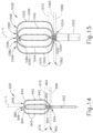
- FIG. 14 shows another exemplary end effector (930) that may be incorporated into catheter assembly (100) in place of end effector (130).
- End effector (930) of this example includes a first arm (940) and a second arm (944).
- Arms (940, 944) extend distally from distal end (924) of catheter shaft (922).
- Each arm (940) forms a respective distal bend (946), with distal bends (946) being located at the same longitudinal distance from distal end (924) of catheter shaft (922).
- Arms (940, 944) overlap each other at an overlap point (980). Longitudinally intermediate regions of arms (940, 944) are generally parallel with each other.
- arms (940, 944) converge at distal end (924) of catheter shaft (922).
- Arm (940) is positioned along a first flat plane in this example.
- Arm (944) is positioned along a second flat plane in this example, slightly offset from the first plane of arm (940).
- Arms (940, 944) are also flexible such that arms (940, 944) may be bent laterally away from a central longitudinal axis (L-L), along a path transverse to the planes defined by arms (940, 944), to thereby deform the planes defined by arms (940, 944). Such bending may occur when end effector (930) is pressed laterally against tissue.
- Arms (940, 944) may be resiliently biased to return to the flat, planar configuration shown in FIG. 14 .
- portions of arms (940, 944) are further offset from each other such that arms (940, 944) are not positioned along a single flat plane.
- arms (940, 944) extend between a proximal plane (966) and an intermediate plane (964) along respective straight paths that are generally parallel with each other and that are generally parallel with the longitudinal axis (L-L) of catheter shaft (922).
- the proximal-most regions of arms (940, 944) between planes (964, 966) together define a generally rectangular first portion (962) of a profile of end effector (930).
- arms (940, 944) define a diverging second portion (970) of a profile of end effector (930).
- Second portion (970) extends from intermediate plane (964) to a distal plane (972). Arms (940, 944) thus extend outwardly along respective diverging paths through second portion (970).
- arms (940, 944) extend along respective straight paths that are parallel with each other as noted above.
- Each arm (940, 944) has a longitudinally spaced array of electrodes (942).
- Each electrode (942) is configured to contact tissue and thereby pick up electrical potentials from the contacted tissue.
- electrodes (942) are provided in pairs like electrodes (146, 148) described above.
- End effector (930) further includes a central inner shaft (950) having a ring electrode (954).
- Ring electrode (954) is coaxially disposed about inner shaft (950).
- ring electrode (954) is longitudinally positioned between planes (964, 972), such that the longitudinal position of ring electrode (954) corresponds with the longitudinal position of second portion (970), and such that ring electrode (954) is enshrouded by second portion (970).
- ring electrode (954) is longitudinally positioned between planes (964, 966), such that the longitudinal position of ring electrode (954) corresponds with the longitudinal position of first portion (962), and such that ring electrode (954) is enshrouded by first portion (962).
- arms (940, 944) may generally prevent tissue from contacting ring electrode (954). Arms (940, 944) nevertheless allow blood to flow through end effector (930), thereby allowing blood to contact ring electrode (954).
- one or more electrodes (942) on arms (940, 944) may contact a tissue surface (T) and thereby pick up electrical potentials at the contacted regions of the tissue surface (T), while ring electrode (954) picks up a reference potential from the blood in which ring electrode (954) is disposed.
- the processor of console (12) may process the potentials from electrodes (942, 954) and thereby provide an electrocardiogram signal as described above.
- the flow of blood around ring electrode (954) may be relatively smooth, which may enable ring electrode (954) to pick up electrical potentials from the blood in a relatively reliable fashion.
- the arrangement of arms (940, 944) around ring electrode (954) may affect the flow of blood around electrode (954) such that the flow is less turbulent than the flow otherwise might be if ring electrode (954) were positioned elsewhere; and such that the pickup of electrical potentials from the blood by ring electrode (954) is more reliable than it otherwise might be if ring electrode (954) were positioned elsewhere.
- the reduction in blood flow turbulence, and increase in sensing reliability by ring electrode (954), may be particularly enhanced when ring electrode (954) is enshrouded by first portion (962).
- arms (1040, 1044, 1046) are generally parallel with each other.
- the proximal ends of arms (1040, 1044, 1046) converge at distal end (1024) of catheter shaft (1022).
- Arm (1040) is positioned along a first flat plane in this example.
- Arm (1044) is positioned along a second flat plane in this example, slightly offset from the first plane of arm (1040).
- Arm (1046) is positioned along a third flat plane in this example, slightly offset from the first and second planes of arm (1040, 1044).
- Arms (1040, 1044, 1046) are also flexible such that arms (1040, 1044, 1046) may be bent laterally away from a central longitudinal axis (L-L), along a path transverse to the planes defined by arms (1040, 1044, 1046), to thereby deform the planes defined by arms (1040, 1044, 1046). Such bending may occur when end effector (1030) is pressed laterally against tissue. Arms (1040, 1044, 1046) may be resiliently biased to return to the flat, planar configuration shown in FIG. 15 . In some other versions, portions of arms (1040, 1044, 1046) are further offset from each other such that arms (1040, 1044, 1046) are not positioned along a single flat plane.
- the proximal ends of arms (1040, 1044, 1046) extend between a proximal plane (1066) and an intermediate plane (1064) along respective straight paths that are generally parallel with each other and that are generally parallel with the longitudinal axis (L-L) of catheter shaft (1022).
- the proximal-most regions of arms (1040, 1044, 1046) between planes (1064, 1066) together define a generally rectangular first portion (1062) of a profile of end effector (1030).
- arms (1040, 1044, 1046) define a diverging second portion (1070) of a profile of end effector (1030).
- Second portion (1070) extends from intermediate plane (1064) to a distal plane (1072). Arms (1040, 1044, 1046) thus extend outwardly along respective diverging paths through second portion (1070).
- arms (1040, 1044, 1046) extend along respective straight paths that are parallel with each other as noted above.
- Each arm (1040, 1044, 1046) has a longitudinally spaced array of electrodes (1042).
- Each electrode (1042) is configured to contact tissue and thereby pick up electrical potentials from the contacted tissue.
- electrodes (1042) are provided in pairs like electrodes (146, 148) described above.
- End effector (1030) further includes a central inner shaft (1050) having a ring electrode (1054).
- Ring electrode (1054) is coaxially disposed about inner shaft (1050).
- ring electrode (1054) is longitudinally positioned between planes (1064, 1072), such that the longitudinal position of ring electrode (1054) corresponds with the longitudinal position of second portion (1070), and such that ring electrode (1054) is enshrouded by second portion (1070).
- ring electrode (1054) is longitudinally positioned between planes (1064, 1066), such that the longitudinal position of ring electrode (1054) corresponds with the longitudinal position of first portion (1062), and such that ring electrode (1054) is enshrouded by first portion (1062).
- arms (1040, 1044, 1046) may generally prevent tissue from contacting ring electrode (1054). Arms (1040, 1044, 1046) nevertheless allow blood to flow through end effector (1030), thereby allowing blood to contact ring electrode (1054).
- one or more electrodes (1042) on arms (1040, 1044, 1046) may contact a tissue surface (T) and thereby pickup electrical potentials at the contacted regions of the tissue surface (T), while ring electrode (1054) picks up a reference potential from the blood in which ring electrode (1054) is disposed.
- the processor of console (12) may process the potentials from electrodes (1042, 1054) and thereby provide an electrocardiogram signal as described above.
- the flow ofblood around ring electrode (1054) may be relatively smooth, which may enable ring electrode (1054) to pick up electrical potentials from the blood in a relatively reliable fashion.
- the arrangement of arms (1040, 1044, 1046) around ring electrode (1054) may affect the flow of blood around electrode (1054) such that the flow is less turbulent than the flow otherwise might be if ring electrode (1054) were positioned elsewhere; and such that the pickup of electrical potentials from the blood by ring electrode (1054) is more reliable than it otherwise might be if ring electrode (1054) were positioned elsewhere.
- the reduction in blood flow turbulence, and increase in sensing reliability by ring electrode (1054) may be particularly enhanced when ring electrode (1054) is enshrouded by first portion (1062).
- FIG. 16 shows another exemplary end effector (1130) that may be incorporated into catheter assembly (100) in place of end effector (130).
- End effector (1130) of this example includes a pair of outer arms (1140) and a pair of outer arms (1144). Arms (1140, 1444) extend distally from distal end (1124) of catheter shaft (1122). Each arm (1140) distally terminates at a free end (1146). Longitudinally intermediate and distal regions of arms (1140, 1444) are generally parallel with each other. The proximal ends of arms (1140, 1444) converge at distal end (1124) of catheter shaft (1122). Arms (1140, 1444) are positioned along a single flat plane in this example.
- arms (1140, 1444) are also flexible such that arms (1140, 1444) may be bent laterally away from a central longitudinal axis (L-L), along a path transverse to the plane defined by arms (1140, 1444), to thereby deform the plane defined by arms (1140, 1444). Such bending may occur when end effector (1130) is pressed laterally against tissue. Arms (1140, 1444) may be resiliently biased to return to the flat, planar configuration shown in FIG. 16 . In some other versions, portions of arms (1140, 1444) are further offset from each other such that arms (1140, 1444) are not positioned along a single flat plane.
- arms (1140, 1444) extend between a proximal plane (1164) and a distal plane (1172) along respective paths that diverge outwardly away from each other and away from the longitudinal axis (L-L) of catheter shaft (1122).
- arms (1140, 1444) extend along respective straight paths that are parallel with each other as noted above.
- Each arm (1140, 1444) has a longitudinally spaced array of electrodes (1142).
- Each electrode (1142) is configured to contact tissue and thereby pick up electrical potentials from the contacted tissue.
- electrodes (1142) are provided in pairs like electrodes (146, 148) described above.
- End effector (1130) further includes a central inner shaft (1150) having a ring electrode (1154).
- Ring electrode (1154) is coaxially disposed about inner shaft (1150).
- ring electrode (1154) is longitudinally positioned between planes (1164, 1172), such that the longitudinal position of ring electrode (1154) corresponds with the longitudinal position of diverging portion (1170), and such that ring electrode (1154) is enshrouded by diverging portion (1170).
- arms (1140, 1444) may generally prevent tissue from contacting ring electrode (1154). Arms (1140, 1444) nevertheless allow blood to flow through end effector (1130), thereby allowing blood to contact ring electrode (1154).
- one or more electrodes (1142) on arms (1140, 1444) may contact a tissue surface (T) and thereby pick up electrical potentials at the contacted regions of the tissue surface (T), while ring electrode (1154) picks up a reference potential from the blood in which ring electrode (1154) is disposed.
- the processor of console (12) may process the potentials from electrodes (1142, 1154) and thereby provide an electrocardiogram signal as described above.
- the flow of blood around ring electrode (1154) may be relatively smooth, which may enable ring electrode (1154) to pick up electrical potentials from the blood in a relatively reliable fashion.
- the arrangement of arms (1140, 1444) around ring electrode (1154) may affect the flow of blood around electrode (1154) such that the flow is less turbulent than the flow otherwise might be if ring electrode (1154) were positioned elsewhere; and such that the pickup of electrical potentials from the blood by ring electrode (1154) is more reliable than it otherwise might be if ring electrode (1154) were positioned elsewhere.
- the reduction in blood flow turbulence, and increase in sensing reliability by ring electrode (1154), may be particularly enhanced when ring electrode (1154) is enshrouded by diverging portion (1170).
- any of the foregoing end effectors may be constructed and operable in accordance with at least some of the teachings of U.S. Pub. No. 2016/0374753, entitled “Catheter Having Closed Loop Array with In-Plane Linear Electrode Portion,” published December 29, 2016 ; U.S. Pub. No. 2018/0056038, entitled “Catheter with Bipole Electrode Spacer and Related Methods,” published March 1, 2018 ; U.S. Pat. No.
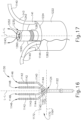
- FIG. 17 shows an enlarged perspective view of an end effector (1230) with tip (1240) that may be incorporated into catheter assembly (100).
- end effector (1230) may be provided in place of central shaft (150) for the examples shown in FIGS. 3-6 or in place of central inner shafts (550, 650, 750, 850, 950, 1050, 1150) for the examples shown in FIGS. 10-16 .
- End effector (1230) of this example includes an irrigating tip (1240) positioned at a distal end (1224) of a catheter shaft (1222).
- Irrigating tip (1240) defines a hollow interior and includes a main opening (1242) located contiguous to an end (1252) of irrigating tip (1240).
- An irrigation lumen (not shown) is provided for the main opening (1242) that extends along the length of catheter shaft (1222) and is in fluid communication with the hollow interior (1243) of irrigating tip (1240). Irrigation fluid communicated from the irrigation lumen to the hollow interior of irrigating tip (1240) will be expelled through main opening (1242).
- reference electrode (1260) is shown as being proximal to the distal end of irrigating tip (1240) in FIG. 17 and on the outside surface of tip (1240), it is within the scope of this application to have a reference electrode (1260) positioned in the hollow interior (1243) of irrigating tip (1240). Wiring (1262) for electrode (1260) may be embedded in the extruded tip or suitably mounted to the irrigating lumen. In versions where reference electrode (1260) is recessed in hollow interior (1243), reference electrode (1260) remains exposed within hollow interior (1243) of irrigating tip (1240) such that blood may enter hollow interior (1243) of irrigating tip (1240) via main opening (1242) and contact reference electrode (1260).
- reference electrode (1260) may pick up a reference potential from blood, saline, or other fluid that passes through hollow interior (1243) of irrigating tip (1240). During use of end effector (1230), the reference electrode (1260) picks up a reference potential from the blood or saline, etc. that enters hollow interior (1243) of irrigating tip (1240) (e.g., via opening (1242) or otherwise).
- the processor of console (12) may process the potentials from irrigating tip (1240) and reference electrode (1260) and thereby provide an electrocardiogram signal as described above.
- reference electrode (1260) When reference electrode (1260) is used to pickup a reference potential from blood or saline that enters hollow interior (1243) of irrigating tip (1240) via opening (1242), the operator may cease communication of irrigation fluid to irrigating tip (1240) to thereby allow the blood to enter tip opening (1242).
- suction is briefly communicated to irrigating tip (1240) to draw blood into the hollow interior (1243) of irrigating tip (1240) via lateral openings (1242).
- a separate suction lumen may extend along catheter shaft (1222).
- the irrigation lumen may be operable to alternate between a state in which irrigation fluid is communicated to irrigating tip (1240) and a state in which suction is communicated to irrigating tip (1240).
- suction may be very brief-just long enough to draw a sufficient amount of blood into the hollow interior of irrigating tip (1240) via lateral openings (1242) to contact reference electrode (1260) for a sufficient duration to pick up a reference potential from the blood.
- suction may be incorporated into end effector (1230) will be apparent to those skilled in the art in view of the teachings herein.
- end effector (1230) may completely lack suction capability.
- FIG. 18 shows another exemplary end effector (1330) that may be incorporated into catheter assembly (100) in place of end effector (130).
- End effector (1330) of this example includes an expandable assembly (1380) and a lasso catheter (1332).
- Expandable assembly (1380) is positioned at a distal end (1324) of a catheter shaft (1322).
- Expandable assembly (1380) includes an expandable balloon (1382) (shown in an expanded state in FIG. 18 ) and an angularly spaced array of flex circuit assemblies (1390).
- Each flex circuit assembly (1390) includes a flexible substrate (1392) that is secured to balloon (1382).
- Each flex circuit assembly (1390) further includes an electrode (1394) secured to the corresponding flexible substrate (1392). Electrodes (1394) are operable to apply RF energy to tissue to thereby ablate the tissue.
- a hub member (1384) is secured to the distal end of balloon (1382). Flex circuit assemblies (1390) distally terminate at hub member (1384).
- Lasso catheter (1332) is coaxially disposed in catheter shaft (1322) and expandable assembly (1380) and extends distally through a central opening (1386) formed in hub member (1384) of expandable assembly (1380).
- lasso catheter (1332) is translatable relative to expandable assembly (1380) to thereby enable selective proximal retraction and distal extension of lasso catheter (1332) relative to expandable assembly.
- Lasso catheter (1332) includes a flexible body (1340) distally terminating in a tip (1350). Body (1340) is resiliently biased to assume the coiled configuration shown in FIG. 18 .
- a plurality of electrodes (1342) are longitudinally spaced apart from each other along the coiled portion of body (1340). Electrodes (1342) are operable to contact tissue (T) and thereby pick up electrical potentials from the contacted tissue (T).
- one or more electrodes (1342) of lasso catheter (1332) may contact a tissue surface (T) and thereby pick up electrical potentials at the contacted regions of the tissue surface (T), while ring electrode (1360) picks up a reference potential from the blood that contacts ring electrode (1360).
- the processor of console (12) may process the potentials from electrodes (1342, 1360) and thereby provide an electrocardiogram signal as described above.
- end effector (1330) may be constructed and operable in accordance with at least some of the teachings of U.S. Pub. No. 2017/0312022, entitled “Irrigated Balloon Catheter with Flexible Circuit Electrode Assembly,” published November 2, 2017 .
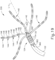
- Reference electrode (362) is positioned in a window (360) formed through catheter shaft (122) such that reference electrode (362) is recessed relative to the outer surface of catheter shaft (122). This recessed positioning may prevent reference electrode (362) from contacting tissue. Blood may nevertheless reach reference electrode (362) via window (360), such that reference electrode (362) may pick up a reference potential from blood that contacts reference electrode (362) via window (360).
- one or more electrodes (146, 148) contacting tissue surface (T) may pick up electrical potentials at the contacted regions of the tissue surface (T), while reference electrode (362) picks up a reference potential from the blood contacting reference electrode (362).
- the processor of console (12) may process the potentials from electrodes (146, 148, 362) and thereby provide an electrocardiogram signal as described above.
- end effector (330) may be constructed and operable in accordance with at least some of the teachings of U.S. Pub. No. 2016/0374753, entitled “Catheter Having Closed Loop Array with In-Plane Linear Electrode Portion,” published December 29, 2016 ; U.S. Pub. No. 2018/0056038, entitled “Catheter with Bipole Electrode Spacer and Related Methods,” published March 1, 2018 ; U.S. Pat. No. 9,907,480, entitled “Catheter Spine Assembly with Closely-Spaced Bipole Microelectrodes,” issued March 6, 2018 ; U.S. Pat. No.
- any of the other above-described catheter shafts may incorporate a recessed reference electrode (362) in a manner similar to catheter shaft (122) as described above with reference to FIG. 19 .
- Such a modification may be provided in addition to or in lieu of providing electrode (154, 254, 554, 654, 754, 854, 954, 1054, 1154, 1260, 1360) as described above.
- FIG. 20 shows another exemplary end effector (430) that may be incorporated into catheter assembly (100) in place of end effector (130).
- End effector (430) of this example is configured and operable substantially like end effector (130) described above, such that like components will not be described in further detail here.
- end effector (430) of this example includes a central shaft (450) with a distal opening (452) that is operable to dispense irrigation fluid.
- central shaft (450) of this example lacks a ring electrode (154). Instead, a reference electrode (462) is positioned on catheter shaft (122) at a location proximal to arms (140) and ring electrodes (132).
- Reference electrode (462) is positioned underneath a cover-like member or tissue guard (460).
- Tissue guard (460) fully encompasses reference electrode (462) and is configured to permit blood to contact reference electrode (462) while preventing tissue from contacting reference electrode (462).
- Tissue guard (460) is not electrically conductive.
- tissue guard (460) may be formed of a mesh material, a porous structure, a band with several openings formed therein, or any other suitable kind of construction as will be apparent to those skilled in the art in view of the teachings herein.
- Reference electrode (462) is operable to pick up a reference potential from blood that contacts reference electrode (462) via tissue guard (460).
- one or more electrodes (146, 148) contacting tissue surface (T) may pick up electrical potentials at the contacted regions of the tissue surface (T), while reference electrode (462) picks up a reference potential from the blood contacting reference electrode (462).
- the processor of console (12) may process the potentials from electrodes (146, 148, 462) and thereby provide an electrocardiogram signal as described above.
- end effector (430) may be constructed and operable in accordance with at least some of the teachings of U.S. Pub. No. 2016/0374753, entitled “Catheter Having Closed Loop Array with In-Plane Linear Electrode Portion,” published December 29, 2016 ; U.S. Pub. No. 2018/0056038, entitled “Catheter with Bipole Electrode Spacer and Related Methods,” published March 1, 2018 ; U.S. Pat. No. 9,907,480 , entitled "Catheter Spine Assembly with Closely-Spaced Bipole
- any of the other above-described catheter shafts may incorporate a reference electrode (462) with a tissue guard (460) in a manner similar to catheter shaft (122) as described above with reference to FIG. 20 .
- a reference electrode 462
- tissue guard 460
- Such a modification may be provided in addition to or in lieu of providing electrode (154, 254, 554, 654, 754, 854, 954, 1054, 1154, 1260, 1360) as described above.
- Electrodes 146, 148, 232, 234, 542, 642, 742, 842, 942, 1042, 1142, 1342 that are configured to contact tissue.
- At least one electrode (146,148, 232, 234, 542, 642, 742, 842, 942, 1042, 1142, 1342) may be in contact with tissue
- at least one other electrode (146, 148, 232, 234, 542, 642, 742, 842, 942, 1042, 1142, 1342) may not be in contact with tissue.
- Such a non-tissue-contacting electrode (146, 148, 232, 234, 542, 642, 742, 842, 942, 1042, 1142, 1342) may nevertheless be in contact with blood.
- Such a non-tissue-contacting electrode (146, 148, 232, 234, 542, 642, 742, 842, 942, 1042, 1142, 1342) may thus serve as a reference electrode, just like electrode (154, 254, 554, 654, 754, 854, 954, 1054, 1154, 1260, 1360) described above. In such instances, electrode (154, 254, 554, 654, 754, 854, 954, 1054, 1154, 1260, 1360) may be omitted.
- the physician may observe the signals being picked up by electrode (146, 148, 232, 234, 542, 642, 742, 842, 942, 1042, 1142, 1342) to identify an electrode (146, 148, 232, 234, 542, 642, 742, 842, 942, 1042, 1142, 1342) that is not contacting tissue. Such observations may be made based on signal readouts being rendered via display (18) of guidance and drive system (10).
- the physician (PH) may flag the non-tissue-contacting electrode (146, 148, 232, 234, 542, 642, 742, 842, 942, 1042, 1142, 1342) as the reference electrode. In some instances, the physician (PH) may also flag a particular tissue-contacting electrode (146, 148, 232, 234, 542, 642, 742, 842, 942, 1042, 1142, 1342) for comparison with the user-identified reference electrode.
- the processor of console (12) may then process the potentials from the user-identified reference electrode (146, 148, 232, 234, 542, 642, 742, 842, 942, 1042, 1142, 1342) and from a tissue-contacting electrode (146, 148, 232, 234, 542, 642, 742, 842, 942, 1042, 1142, 1342) and thereby provide an electrocardiogram signal as described above.
- the processor of console (12) may automatically identify a non-tissue-contacting electrode (146, 148, 232, 234, 542, 642, 742, 842, 942, 1042, 1142, 1342) and flag that non-tissue-contacting electrode (146, 148, 232, 234, 542, 642, 742, 842, 942, 1042, 1142, 1342) as the reference electrode.
- processor of console (12) may identify which electrodes (146, 148, 232, 234, 542, 642, 742, 842, 942, 1042, 1142, 1342) are contacting tissue and which electrodes (146, 148, 232, 234, 542, 642, 742, 842, 942, 1042, 1142, 1342) are not contacting tissue based on the impedance at electrodes (146, 148, 232, 234, 542, 642, 742, 842, 942, 1042, 1142, 1342).
- a non-tissue-contacting electrode (146, 148, 232, 234, 542, 642, 742, 842, 942, 1042, 1142, 1342) may have a lower impedance than a tissue-contacting electrode (146, 148, 232, 234, 542, 642, 742, 842, 942, 1042, 1142, 1342).
- the processor of console (12) may check the impedance between a dedicated reference electrode (154, 254, 554, 654, 754, 854, 954, 1054, 1154, 1260, 1360) and each of the sensor electrodes (146, 148, 232, 234, 542, 642, 742, 842, 942, 1042, 1142, 1342) to identify which sensor electrode(s) (146, 148, 232, 234, 542, 642, 742, 842, 942, 1042, 1142, 1342) is/are contacting tissue and which sensor electrode(s) (146, 148, 232, 234, 542, 642, 742, 842, 942, 1042, 1142, 1342) is/are not contacting tissue.
- the processor of console (12) may use this information in any suitable fashion as will be apparent to those skilled in the art in view of the teachings herein.
- each end effector (130, 200, 330, 430, 530, 630, 730, 830, 930, 1030, 1130, 1330) described herein has at least one tissue-contacting electrode (146, 148, 232, 234, 542, 642, 742, 842, 942, 1042, 1142, 1240, 1342) and at least one non-tissue-contacting electrode (146, 148, 154, 232, 234, 254, 542, 554, 642, 654, 742, 754, 842, 854, 942, 954, 1042, 1054, 1142, 1154, 1260, 1342, 1360).
- tissue-contacting electrode 146, 148, 232, 234, 542, 642, 742, 842, 942, 1042, 1142, 1240, 1342
- non-tissue-contacting electrode 146, 148, 154, 232, 234, 254, 542, 554, 642, 654, 742, 754, 842, 854, 942, 954, 1042, 1054, 11
- the non-tissue-contacting electrode may be physically prevented from contacting tissue by other structures of end effector (130, 200, 330, 430, 530, 630, 730, 830, 930, 1030, 1130, 1330).
- the non-tissue-contacting electrode (146, 148, 232, 234, 542, 642, 742, 842, 942, 1042, 1142, 1342) is just incidentally not contacting tissue at a particular stage of the EP mapping procedure.
- any of the instruments described herein may be cleaned and sterilized before and/or after a procedure.
- the device is placed in a closed and sealed container, such as a plastic or TYVEK bag.
- the container and device may then be placed in a field of radiation that can penetrate the container, such as gamma radiation, x-rays, or high-energy electrons.
- the radiation may kill bacteria on the device and in the container.
- the sterilized device may then be stored in the sterile container for later use.
- a device may also be sterilized using any other technique known in the art, including but not limited to beta or gamma radiation, ethylene oxide, hydrogen peroxide, peracetic acid, and vapor phase sterilization, either with or without a gas plasma, or steam.
- a solution may comprise a chemical selected from a group consisting of: 3300-3800 ppm peracetic acid; 2.65% glutaraldehyde; 3.4% glutaraldehyde with 26% isopropanol; 3.5% glutaraldehyde; 5.75% ortho-phthaldehyde; 0.55% ortho-phthaldehyde; hypochlorite with hypochlorous acid 650-675 ppm active free chlorine; 1.12% glutaraldehyde with 1.93% phenol/phenate; 2.5% glutaraldehyde; 3.2% glutaraldehyde; 3% glutaraldehyde; 7.35% hydrogen peroxide with 0.23% peracetic acid; 1.0% hydrogen peroxide with 0.08% peracetic acid; 2.4% glutaraldehyde; 3.
- such a solution may comprise a chemical selected from a group consisting of: 3100-3400 ppm peracetic acid; 3.4% glutaraldehyde with 20.1% isopropanol; 2.0% hydrogen peroxide; at least 1820 mg/L peracetic acid; 0.575% ortho-phthalaldehyde; 0.60% ortho-phthalaldehyde; hypochlorite and hypochlorous acid with 650-675 ppm active free chlorine; 0.55% ortho-phthalaldehyde; 7.5% hydrogen peroxide; 2.6% glutaraldehyde; hypochlorite and hypochlorous acid with 400-450 ppm active free chlorine; 0.55% ortho-phthalaldehyde; and combinations thereof.
- the cleaning and/or sterilization procedures may be carried out in accordance with the U.S. Food & Drug Administration guidelines as published at https://www.fda.gov/medical-devices/reprocessing-reusable-medical-devices-information-manufacturers/fda-cleared-sterilants-and-high-level-disinfectants-general-claims-processing-reusable-medical-and.
Landscapes
- Health & Medical Sciences (AREA)
- Life Sciences & Earth Sciences (AREA)
- Engineering & Computer Science (AREA)
- Surgery (AREA)
- Veterinary Medicine (AREA)
- General Health & Medical Sciences (AREA)
- Public Health (AREA)
- Biomedical Technology (AREA)
- Heart & Thoracic Surgery (AREA)
- Medical Informatics (AREA)
- Molecular Biology (AREA)
- Physics & Mathematics (AREA)
- Animal Behavior & Ethology (AREA)
- Plasma & Fusion (AREA)
- Nuclear Medicine, Radiotherapy & Molecular Imaging (AREA)
- Otolaryngology (AREA)
- Pathology (AREA)
- Biophysics (AREA)
- Cardiology (AREA)
- Physiology (AREA)
- Surgical Instruments (AREA)
- Measurement And Recording Of Electrical Phenomena And Electrical Characteristics Of The Living Body (AREA)
- Electrotherapy Devices (AREA)
Claims (1)
- Vorrichtung, umfassend:(a) eine Welle (1222); und(b) ein Spitzenelement (1240), das an einem distalen Ende (1224) der Welle (1222) positioniert ist, wobei das Spitzenelement (1240) eine integrierte Elektrode ohne Gewebekontakt aufweist und einen hohlen Innenraum (1243) und eine Öffnung (1242) in Fluidverbindung mit dem hohlen Innenraum definiert; und(c) mindestens ein Paar Stacheln (140), die sich von dem distalen Ende (1224) der Welle (1222) entlang einer Längsachse erstrecken, um ein virtuelles Volumen um das Spitzenelement (1240) herum zu definieren;wobei die Elektrode ohne Gewebekontakt (1260) in der Nähe der Öffnung des Spitzenelements (1240) positioniert ist und konfiguriert ist, um ein Referenzpotential aufzunehmen, undwobei das Spitzenelement (1240) konfiguriert ist, um einen Kontakt der Elektrode ohne Gewebekontakt (1260) mit Gewebe zu verhindern, undwobei die Elektrode ohne Gewebekontakt (1260) innerhalb des hohlen Innenraums angeordnet ist.
Priority Applications (1)
| Application Number | Priority Date | Filing Date | Title |
|---|---|---|---|
| EP24194074.1A EP4437989A3 (de) | 2018-08-03 | 2019-08-02 | Unipolare referenzelektrode für einen katheter zur elektrophysiologischen abbildung |
Applications Claiming Priority (2)
| Application Number | Priority Date | Filing Date | Title |
|---|---|---|---|
| US201862714110P | 2018-08-03 | 2018-08-03 | |
| US16/451,263 US20200038101A1 (en) | 2018-08-03 | 2019-06-25 | Unipolar reference electrode for electrophysiology mapping catheter |
Related Child Applications (1)
| Application Number | Title | Priority Date | Filing Date |
|---|---|---|---|
| EP24194074.1A Division EP4437989A3 (de) | 2018-08-03 | 2019-08-02 | Unipolare referenzelektrode für einen katheter zur elektrophysiologischen abbildung |
Publications (4)
| Publication Number | Publication Date |
|---|---|
| EP3603493A2 EP3603493A2 (de) | 2020-02-05 |
| EP3603493A3 EP3603493A3 (de) | 2020-04-15 |
| EP3603493B1 true EP3603493B1 (de) | 2024-08-14 |
| EP3603493C0 EP3603493C0 (de) | 2024-08-14 |
Family
ID=67544030
Family Applications (2)
| Application Number | Title | Priority Date | Filing Date |
|---|---|---|---|
| EP24194074.1A Pending EP4437989A3 (de) | 2018-08-03 | 2019-08-02 | Unipolare referenzelektrode für einen katheter zur elektrophysiologischen abbildung |
| EP19189827.9A Active EP3603493B1 (de) | 2018-08-03 | 2019-08-02 | Unipolare referenzelektrode für einen elektrophysiologieabbildungskatheter |
Family Applications Before (1)
| Application Number | Title | Priority Date | Filing Date |
|---|---|---|---|
| EP24194074.1A Pending EP4437989A3 (de) | 2018-08-03 | 2019-08-02 | Unipolare referenzelektrode für einen katheter zur elektrophysiologischen abbildung |
Country Status (10)
| Country | Link |
|---|---|
| US (1) | US20200038101A1 (de) |
| EP (2) | EP4437989A3 (de) |
| JP (1) | JP7391562B2 (de) |
| KR (1) | KR20200015883A (de) |
| CN (3) | CN110786926B (de) |
| AU (1) | AU2019210560A1 (de) |
| BR (1) | BR102019015932A2 (de) |
| CA (1) | CA3051091A1 (de) |
| IL (1) | IL268310B2 (de) |
| RU (1) | RU2019123599A (de) |
Cited By (1)
| Publication number | Priority date | Publication date | Assignee | Title |
|---|---|---|---|---|
| US12551658B2 (en) | 2023-03-16 | 2026-02-17 | St. Jude Medical, Cardiology Division, Inc. | Steerable introducer with slide block divider |
Families Citing this family (21)
| Publication number | Priority date | Publication date | Assignee | Title |
|---|---|---|---|---|
| US12350050B2 (en) * | 2014-04-14 | 2025-07-08 | Recor Medical, Inc. | Intraluminal microneurography probes and related systems and methods |
| US20200038101A1 (en) * | 2018-08-03 | 2020-02-06 | Biosense Webster (Israel) Ltd. | Unipolar reference electrode for electrophysiology mapping catheter |
| WO2020092249A1 (en) * | 2018-10-28 | 2020-05-07 | Cardiac Pacemakers, Inc. | Implantable medical device having two electrodes in the header |
| US11850051B2 (en) | 2019-04-30 | 2023-12-26 | Biosense Webster (Israel) Ltd. | Mapping grid with high density electrode array |
| US20210121231A1 (en) * | 2019-10-23 | 2021-04-29 | Biosense Webster (Israel) Ltd. | Cardiac mapping catheter with square-spaced electrodes |
| US20210369132A1 (en) | 2020-05-29 | 2021-12-02 | Biosense Webster (Israel) Ltd. | Intraluminal reference electrode for cardiovascular treatment apparatus |
| EP4477171B1 (de) | 2020-05-29 | 2025-12-24 | Biosense Webster (Israel) Ltd. | Intraluminale referenzelektrode für kardiovaskuläre behandlungsvorrichtung |
| JP7515637B2 (ja) | 2020-08-18 | 2024-07-12 | セント・ジュード・メディカル,カーディオロジー・ディヴィジョン,インコーポレイテッド | 磁気位置の追跡を伴う高密度電極カテーテル |
| US12016612B2 (en) * | 2020-08-19 | 2024-06-25 | Acclarent, Inc. | ENT ablation instrument with electrode loop |
| CN112618002B (zh) * | 2020-12-14 | 2025-07-15 | 绍兴梅奥心磁医疗科技有限公司 | 正交电极脉冲电场消融导管 |
| US12121229B2 (en) * | 2021-02-05 | 2024-10-22 | Shenzhen Institutes Of Advanced Technology Chinese Academy Of Sciences | Soft-bodied apparatus and method for opening eyelid |
| JP2024528078A (ja) | 2021-07-30 | 2024-07-26 | バイオセンス・ウエブスター・(イスラエル)・リミテッド | 灌注を伴う平面エンドエフェクタ |
| US12533489B2 (en) | 2021-10-08 | 2026-01-27 | Biosense Webster (Israel) Ltd. | Measuring tissue proximity for multi-electrode catheter |
| CN114668482A (zh) * | 2022-01-28 | 2022-06-28 | 心航路医学科技(广州)有限公司 | 双层网篮导管装置 |
| US20240156524A1 (en) * | 2022-11-11 | 2024-05-16 | Biosense Webster (Israel) Ltd. | Electrode catheter with corrugated support structure |
| US20240407696A1 (en) * | 2023-06-09 | 2024-12-12 | Biosense Webster (Israel) Ltd. | Medical probe with concentric reference and sense electrodes |
| US20250049345A1 (en) * | 2023-08-10 | 2025-02-13 | Biosense Webster (Israel) Ltd. | Impedance-based navigation of sheath |
| US20250186109A1 (en) * | 2023-12-06 | 2025-06-12 | Biosense Webster (Israel) Ltd. | Reference electrode dedicated to catheter tissue proximity estimation |
| CN118383773A (zh) * | 2023-12-12 | 2024-07-26 | 上海微创电生理医疗科技股份有限公司 | 一种高密度标测导管 |
| CN117752404B (zh) * | 2024-02-22 | 2024-05-07 | 四川锦江电子医疗器械科技股份有限公司 | 一种心脏电生理标测和消融导管 |
| CN119564327B (zh) * | 2025-02-10 | 2025-10-03 | 四川锦江电子医疗器械科技股份有限公司 | 一种能够进行局部消融的导管 |
Family Cites Families (41)
| Publication number | Priority date | Publication date | Assignee | Title |
|---|---|---|---|---|
| CA2109793A1 (en) * | 1991-05-24 | 1992-12-10 | Stuart D. Edwards | Combination monophasic action potential/ablation catheter and high-performance filter system |
| US5782239A (en) * | 1992-06-30 | 1998-07-21 | Cordis Webster, Inc. | Unique electrode configurations for cardiovascular electrode catheter with built-in deflection method and central puller wire |
| US5738096A (en) | 1993-07-20 | 1998-04-14 | Biosense, Inc. | Cardiac electromechanics |
| US6325972B1 (en) | 1998-12-30 | 2001-12-04 | Ethicon, Inc. | Apparatus and process for concentrating a liquid sterilant and sterilizing articles therewith |
| US6852279B2 (en) | 2002-06-28 | 2005-02-08 | Ethicon, Inc. | Sterilization with temperature-controlled diffusion path |
| US6365102B1 (en) | 1999-03-31 | 2002-04-02 | Ethicon, Inc. | Method of enhanced sterilization with improved material compatibility |
| US6569160B1 (en) | 2000-07-07 | 2003-05-27 | Biosense, Inc. | System and method for detecting electrode-tissue contact |
| US6546270B1 (en) * | 2000-07-07 | 2003-04-08 | Biosense, Inc. | Multi-electrode catheter, system and method |
| US6408199B1 (en) * | 2000-07-07 | 2002-06-18 | Biosense, Inc. | Bipolar mapping of intracardiac potentials with electrode having blood permeable covering |
| US6447719B1 (en) | 2000-10-02 | 2002-09-10 | Johnson & Johnson | Power system for sterilization systems employing low frequency plasma |
| US6852277B2 (en) | 2000-10-02 | 2005-02-08 | Ethicon, Inc. | Sterilization system employing a switching module adapted to pulsate the low frequency power applied to a plasma |
| US8280477B2 (en) * | 2009-07-29 | 2012-10-02 | Medtronic Cryocath Lp | Mono-phasic action potential electrogram recording catheter, and method |
| US20110028962A1 (en) * | 2009-07-31 | 2011-02-03 | Randell Werneth | Adjustable pulmonary vein ablation catheter |
| KR101820542B1 (ko) | 2009-11-11 | 2018-01-19 | 호라이라 인코포레이티드 | 조직을 치료하고 협착을 제어하기 위한 방법, 기구 및 장치 |
| US10743932B2 (en) | 2011-07-28 | 2020-08-18 | Biosense Webster (Israel) Ltd. | Integrated ablation system using catheter with multiple irrigation lumens |
| US8956353B2 (en) | 2011-12-29 | 2015-02-17 | Biosense Webster (Israel) Ltd. | Electrode irrigation using micro-jets |
| US9314299B2 (en) * | 2012-03-21 | 2016-04-19 | Biosense Webster (Israel) Ltd. | Flower catheter for mapping and ablating veinous and other tubular locations |
| CN103315808A (zh) * | 2012-03-23 | 2013-09-25 | 心诺普医疗技术(北京)有限公司 | 一种消融电极及采用该电极的灌注型电极导管 |
| US9031642B2 (en) * | 2013-02-21 | 2015-05-12 | Medtronic, Inc. | Methods for simultaneous cardiac substrate mapping using spatial correlation maps between neighboring unipolar electrograms |
| US9480416B2 (en) | 2014-01-17 | 2016-11-01 | Biosense Webster (Israel) Ltd. | Signal transmission using catheter braid wires |
| US9597140B2 (en) * | 2014-01-31 | 2017-03-21 | Medtronic Cryocath Lp | Accessory to allow sensing at balloon interface |
| US20170296084A1 (en) * | 2014-09-18 | 2017-10-19 | University Of Utah Research Foundation | Cardiac mapping catheter |
| US9788893B2 (en) | 2014-11-20 | 2017-10-17 | Biosense Webster (Israel) Ltd. | Catheter with soft distal tip for mapping and ablating tubular region |
| US9820664B2 (en) * | 2014-11-20 | 2017-11-21 | Biosense Webster (Israel) Ltd. | Catheter with high density electrode spine array |
| US9801585B2 (en) | 2014-12-31 | 2017-10-31 | Biosense Webster (Israel) Ltd. | Electrocardiogram noise reduction |
| US9833161B2 (en) * | 2015-02-09 | 2017-12-05 | Biosense Webster (Israel) Ltd. | Basket catheter with far-field electrode |
| US9949656B2 (en) | 2015-06-29 | 2018-04-24 | Biosense Webster (Israel) Ltd. | Catheter with stacked spine electrode assembly |
| US10537259B2 (en) | 2015-06-29 | 2020-01-21 | Biosense Webster (Israel) Ltd. | Catheter having closed loop array with in-plane linear electrode portion |
| US20170007157A1 (en) * | 2015-07-08 | 2017-01-12 | Rainbow Medical Ltd. | Electrical-signal-based electrode-tissue contact detection |
| US20170027465A1 (en) * | 2015-07-31 | 2017-02-02 | University Of Utah Research Foundation | Systems and methods for characterizing the conductive properties of the heart |
| US20170049497A1 (en) * | 2015-08-21 | 2017-02-23 | Medtronic Ablation Frontiers Llc | Array orientation tracker |
| US10130420B2 (en) * | 2015-10-08 | 2018-11-20 | Biosense Webster (Israel) Ltd. | Catheter with membraned spines for pulmonary vein isolation |
| WO2017070559A1 (en) * | 2015-10-21 | 2017-04-27 | St. Jude, Cardiology Division, Inc. | High density electrode mapping catheter |
| US9907480B2 (en) | 2016-02-08 | 2018-03-06 | Biosense Webster (Israel) Ltd. | Catheter spine assembly with closely-spaced bipole microelectrodes |
| US10561753B2 (en) | 2016-03-02 | 2020-02-18 | Asp Global Manufacturing Gmbh | Method of sterilizing medical devices, analyzing biological indicators, and linking medical device sterilization equipment |
| US10660700B2 (en) | 2016-04-28 | 2020-05-26 | Biosense Webster (Israel) Ltd. | Irrigated balloon catheter with flexible circuit electrode assembly |
| WO2017192477A1 (en) * | 2016-05-02 | 2017-11-09 | Affera, Inc. | Method of inserting a catheter with an expandable tip and a system comprising a catheter, a sheath and an insertion sleeve |
| US10702177B2 (en) | 2016-08-24 | 2020-07-07 | Biosense Webster (Israel) Ltd. | Catheter with bipole electrode spacer and related methods |
| US11559349B2 (en) | 2016-09-12 | 2023-01-24 | Biosense Webster (Israel) Ltd. | Ablation catheter with a flexible printed circuit board |
| JP7326341B2 (ja) * | 2018-02-06 | 2023-08-15 | バイオセンス・ウエブスター・(イスラエル)・リミテッド | 互い違い状の微小電極配置を有する医療プローブ |
| US20200038101A1 (en) * | 2018-08-03 | 2020-02-06 | Biosense Webster (Israel) Ltd. | Unipolar reference electrode for electrophysiology mapping catheter |
-
2019
- 2019-06-25 US US16/451,263 patent/US20200038101A1/en active Pending
- 2019-07-26 RU RU2019123599A patent/RU2019123599A/ru unknown
- 2019-07-28 IL IL268310A patent/IL268310B2/en unknown
- 2019-07-31 AU AU2019210560A patent/AU2019210560A1/en not_active Abandoned
- 2019-08-01 BR BR102019015932-4A patent/BR102019015932A2/pt not_active IP Right Cessation
- 2019-08-02 CA CA3051091A patent/CA3051091A1/en not_active Abandoned
- 2019-08-02 EP EP24194074.1A patent/EP4437989A3/de active Pending
- 2019-08-02 CN CN201910711974.3A patent/CN110786926B/zh active Active
- 2019-08-02 JP JP2019142872A patent/JP7391562B2/ja active Active
- 2019-08-02 EP EP19189827.9A patent/EP3603493B1/de active Active
- 2019-08-02 CN CN202510631842.5A patent/CN120284453A/zh active Pending
- 2019-08-02 KR KR1020190094112A patent/KR20200015883A/ko not_active Withdrawn
- 2019-08-02 CN CN201921243575.0U patent/CN213030820U/zh active Active
Cited By (1)
| Publication number | Priority date | Publication date | Assignee | Title |
|---|---|---|---|---|
| US12551658B2 (en) | 2023-03-16 | 2026-02-17 | St. Jude Medical, Cardiology Division, Inc. | Steerable introducer with slide block divider |
Also Published As
| Publication number | Publication date |
|---|---|
| EP3603493A3 (de) | 2020-04-15 |
| IL268310A (en) | 2020-02-27 |
| BR102019015932A2 (pt) | 2020-02-04 |
| US20200038101A1 (en) | 2020-02-06 |
| JP7391562B2 (ja) | 2023-12-05 |
| KR20200015883A (ko) | 2020-02-13 |
| CN110786926B (zh) | 2025-08-05 |
| CA3051091A1 (en) | 2020-02-03 |
| EP3603493A2 (de) | 2020-02-05 |
| AU2019210560A1 (en) | 2020-02-20 |
| EP4437989A3 (de) | 2024-12-04 |
| IL268310B2 (en) | 2025-10-01 |
| CN213030820U (zh) | 2021-04-23 |
| IL268310B1 (en) | 2025-06-01 |
| JP2020018857A (ja) | 2020-02-06 |
| CN120284453A (zh) | 2025-07-11 |
| EP3603493C0 (de) | 2024-08-14 |
| CN110786926A (zh) | 2020-02-14 |
| EP4437989A2 (de) | 2024-10-02 |
| RU2019123599A (ru) | 2021-01-26 |
Similar Documents
| Publication | Publication Date | Title |
|---|---|---|
| EP3603493B1 (de) | Unipolare referenzelektrode für einen elektrophysiologieabbildungskatheter | |
| CN114401687B (zh) | 具有位于可膨胀膜上的薄膜电极的导管 | |
| EP3998975B1 (de) | Ausblühungssegelkatheter mit einer elektrodenanordnung hoher dichte | |
| US20230200895A1 (en) | Catheter end effector with resilient frame and flexible interior | |
| EP4048178B1 (de) | Herzkarthographiekatheter mit gitterförmig beabstandeten elektroden | |
| US20230190367A1 (en) | Catheter end effector with laterally projecting body | |
| US20240138905A1 (en) | Irrigation tubing with regulated fluid emission | |
| US20230310071A1 (en) | Catheter with external magnetic coils | |
| CN116889465A (zh) | 具有外部磁线圈的导管 |
Legal Events
| Date | Code | Title | Description |
|---|---|---|---|
| PUAI | Public reference made under article 153(3) epc to a published international application that has entered the european phase |
Free format text: ORIGINAL CODE: 0009012 |
|
| STAA | Information on the status of an ep patent application or granted ep patent |
Free format text: STATUS: THE APPLICATION HAS BEEN PUBLISHED |
|
| AK | Designated contracting states |
Kind code of ref document: A2 Designated state(s): AL AT BE BG CH CY CZ DE DK EE ES FI FR GB GR HR HU IE IS IT LI LT LU LV MC MK MT NL NO PL PT RO RS SE SI SK SM TR |
|
| AX | Request for extension of the european patent |
Extension state: BA ME |
|
| PUAL | Search report despatched |
Free format text: ORIGINAL CODE: 0009013 |
|
| AK | Designated contracting states |
Kind code of ref document: A3 Designated state(s): AL AT BE BG CH CY CZ DE DK EE ES FI FR GB GR HR HU IE IS IT LI LT LU LV MC MK MT NL NO PL PT RO RS SE SI SK SM TR |
|
| AX | Request for extension of the european patent |
Extension state: BA ME |
|
| RIC1 | Information provided on ipc code assigned before grant |
Ipc: A61B 18/12 20060101ALI20200310BHEP Ipc: A61B 5/00 20060101AFI20200310BHEP Ipc: A61B 18/00 20060101ALI20200310BHEP |
|
| STAA | Information on the status of an ep patent application or granted ep patent |
Free format text: STATUS: REQUEST FOR EXAMINATION WAS MADE |
|
| 17P | Request for examination filed |
Effective date: 20200925 |
|
| RBV | Designated contracting states (corrected) |
Designated state(s): AL AT BE BG CH CY CZ DE DK EE ES FI FR GB GR HR HU IE IS IT LI LT LU LV MC MK MT NL NO PL PT RO RS SE SI SK SM TR |
|
| STAA | Information on the status of an ep patent application or granted ep patent |
Free format text: STATUS: EXAMINATION IS IN PROGRESS |
|
| 17Q | First examination report despatched |
Effective date: 20230419 |
|
| GRAP | Despatch of communication of intention to grant a patent |
Free format text: ORIGINAL CODE: EPIDOSNIGR1 |
|
| STAA | Information on the status of an ep patent application or granted ep patent |
Free format text: STATUS: GRANT OF PATENT IS INTENDED |
|
| RIC1 | Information provided on ipc code assigned before grant |
Ipc: A61B 18/14 20060101ALN20240220BHEP Ipc: A61B 18/00 20060101ALN20240220BHEP Ipc: A61B 5/00 20060101AFI20240220BHEP |
|
| RIC1 | Information provided on ipc code assigned before grant |
Ipc: A61B 18/14 20060101ALN20240226BHEP Ipc: A61B 18/00 20060101ALN20240226BHEP Ipc: A61B 5/00 20060101AFI20240226BHEP |
|
| INTG | Intention to grant announced |
Effective date: 20240314 |
|
| GRAS | Grant fee paid |
Free format text: ORIGINAL CODE: EPIDOSNIGR3 |
|
| GRAA | (expected) grant |
Free format text: ORIGINAL CODE: 0009210 |
|
| STAA | Information on the status of an ep patent application or granted ep patent |
Free format text: STATUS: THE PATENT HAS BEEN GRANTED |
|
| AK | Designated contracting states |
Kind code of ref document: B1 Designated state(s): AL AT BE BG CH CY CZ DE DK EE ES FI FR GB GR HR HU IE IS IT LI LT LU LV MC MK MT NL NO PL PT RO RS SE SI SK SM TR |
|
| REG | Reference to a national code |
Ref country code: GB Ref legal event code: FG4D |
|
| REG | Reference to a national code |
Ref country code: CH Ref legal event code: EP |
|
| REG | Reference to a national code |
Ref country code: DE Ref legal event code: R096 Ref document number: 602019056899 Country of ref document: DE |
|
| REG | Reference to a national code |
Ref country code: IE Ref legal event code: FG4D |
|
| U01 | Request for unitary effect filed |
Effective date: 20240903 |
|
| U07 | Unitary effect registered |
Designated state(s): AT BE BG DE DK EE FI FR IT LT LU LV MT NL PT RO SE SI Effective date: 20240917 |
|
| PG25 | Lapsed in a contracting state [announced via postgrant information from national office to epo] |
Ref country code: NO Free format text: LAPSE BECAUSE OF FAILURE TO SUBMIT A TRANSLATION OF THE DESCRIPTION OR TO PAY THE FEE WITHIN THE PRESCRIBED TIME-LIMIT Effective date: 20241114 |
|
| PG25 | Lapsed in a contracting state [announced via postgrant information from national office to epo] |
Ref country code: GR Free format text: LAPSE BECAUSE OF FAILURE TO SUBMIT A TRANSLATION OF THE DESCRIPTION OR TO PAY THE FEE WITHIN THE PRESCRIBED TIME-LIMIT Effective date: 20241115 Ref country code: PL Free format text: LAPSE BECAUSE OF FAILURE TO SUBMIT A TRANSLATION OF THE DESCRIPTION OR TO PAY THE FEE WITHIN THE PRESCRIBED TIME-LIMIT Effective date: 20240814 |
|
| PG25 | Lapsed in a contracting state [announced via postgrant information from national office to epo] |
Ref country code: IS Free format text: LAPSE BECAUSE OF FAILURE TO SUBMIT A TRANSLATION OF THE DESCRIPTION OR TO PAY THE FEE WITHIN THE PRESCRIBED TIME-LIMIT Effective date: 20241214 |
|
| PG25 | Lapsed in a contracting state [announced via postgrant information from national office to epo] |
Ref country code: HR Free format text: LAPSE BECAUSE OF FAILURE TO SUBMIT A TRANSLATION OF THE DESCRIPTION OR TO PAY THE FEE WITHIN THE PRESCRIBED TIME-LIMIT Effective date: 20240814 |
|
| PG25 | Lapsed in a contracting state [announced via postgrant information from national office to epo] |
Ref country code: RS Free format text: LAPSE BECAUSE OF FAILURE TO SUBMIT A TRANSLATION OF THE DESCRIPTION OR TO PAY THE FEE WITHIN THE PRESCRIBED TIME-LIMIT Effective date: 20241114 Ref country code: ES Free format text: LAPSE BECAUSE OF FAILURE TO SUBMIT A TRANSLATION OF THE DESCRIPTION OR TO PAY THE FEE WITHIN THE PRESCRIBED TIME-LIMIT Effective date: 20240814 |
|
| PG25 | Lapsed in a contracting state [announced via postgrant information from national office to epo] |
Ref country code: RS Free format text: LAPSE BECAUSE OF FAILURE TO SUBMIT A TRANSLATION OF THE DESCRIPTION OR TO PAY THE FEE WITHIN THE PRESCRIBED TIME-LIMIT Effective date: 20241114 Ref country code: PL Free format text: LAPSE BECAUSE OF FAILURE TO SUBMIT A TRANSLATION OF THE DESCRIPTION OR TO PAY THE FEE WITHIN THE PRESCRIBED TIME-LIMIT Effective date: 20240814 Ref country code: NO Free format text: LAPSE BECAUSE OF FAILURE TO SUBMIT A TRANSLATION OF THE DESCRIPTION OR TO PAY THE FEE WITHIN THE PRESCRIBED TIME-LIMIT Effective date: 20241114 Ref country code: IS Free format text: LAPSE BECAUSE OF FAILURE TO SUBMIT A TRANSLATION OF THE DESCRIPTION OR TO PAY THE FEE WITHIN THE PRESCRIBED TIME-LIMIT Effective date: 20241214 Ref country code: HR Free format text: LAPSE BECAUSE OF FAILURE TO SUBMIT A TRANSLATION OF THE DESCRIPTION OR TO PAY THE FEE WITHIN THE PRESCRIBED TIME-LIMIT Effective date: 20240814 Ref country code: GR Free format text: LAPSE BECAUSE OF FAILURE TO SUBMIT A TRANSLATION OF THE DESCRIPTION OR TO PAY THE FEE WITHIN THE PRESCRIBED TIME-LIMIT Effective date: 20241115 Ref country code: ES Free format text: LAPSE BECAUSE OF FAILURE TO SUBMIT A TRANSLATION OF THE DESCRIPTION OR TO PAY THE FEE WITHIN THE PRESCRIBED TIME-LIMIT Effective date: 20240814 |
|
| PG25 | Lapsed in a contracting state [announced via postgrant information from national office to epo] |
Ref country code: SM Free format text: LAPSE BECAUSE OF FAILURE TO SUBMIT A TRANSLATION OF THE DESCRIPTION OR TO PAY THE FEE WITHIN THE PRESCRIBED TIME-LIMIT Effective date: 20240814 |
|
| PG25 | Lapsed in a contracting state [announced via postgrant information from national office to epo] |
Ref country code: CZ Free format text: LAPSE BECAUSE OF FAILURE TO SUBMIT A TRANSLATION OF THE DESCRIPTION OR TO PAY THE FEE WITHIN THE PRESCRIBED TIME-LIMIT Effective date: 20240814 |
|
| PG25 | Lapsed in a contracting state [announced via postgrant information from national office to epo] |
Ref country code: SK Free format text: LAPSE BECAUSE OF FAILURE TO SUBMIT A TRANSLATION OF THE DESCRIPTION OR TO PAY THE FEE WITHIN THE PRESCRIBED TIME-LIMIT Effective date: 20240814 |
|
| PLBE | No opposition filed within time limit |
Free format text: ORIGINAL CODE: 0009261 |
|
| STAA | Information on the status of an ep patent application or granted ep patent |
Free format text: STATUS: NO OPPOSITION FILED WITHIN TIME LIMIT |
|
| 26N | No opposition filed |
Effective date: 20250515 |
|
| U20 | Renewal fee for the european patent with unitary effect paid |
Year of fee payment: 7 Effective date: 20250709 |
|
| PGFP | Annual fee paid to national office [announced via postgrant information from national office to epo] |
Ref country code: GB Payment date: 20250703 Year of fee payment: 7 |