EP3603462B1 - Maschine zur abgabe von aufgussgetränken und dergleichen, insbesondere von der art mit kapseln und/oder hülsen - Google Patents
Maschine zur abgabe von aufgussgetränken und dergleichen, insbesondere von der art mit kapseln und/oder hülsen Download PDFInfo
- Publication number
- EP3603462B1 EP3603462B1 EP19189416.1A EP19189416A EP3603462B1 EP 3603462 B1 EP3603462 B1 EP 3603462B1 EP 19189416 A EP19189416 A EP 19189416A EP 3603462 B1 EP3603462 B1 EP 3603462B1
- Authority
- EP
- European Patent Office
- Prior art keywords
- infusion
- dispensing
- chambers
- pistons
- capsules
- Prior art date
- Legal status (The legal status is an assumption and is not a legal conclusion. Google has not performed a legal analysis and makes no representation as to the accuracy of the status listed.)
- Active
Links
Images


Classifications
-
- A—HUMAN NECESSITIES
- A47—FURNITURE; DOMESTIC ARTICLES OR APPLIANCES; COFFEE MILLS; SPICE MILLS; SUCTION CLEANERS IN GENERAL
- A47J—KITCHEN EQUIPMENT; COFFEE MILLS; SPICE MILLS; APPARATUS FOR MAKING BEVERAGES
- A47J31/00—Apparatus for making beverages
- A47J31/24—Coffee-making apparatus in which hot water is passed through the filter under pressure, i.e. in which the coffee grounds are extracted under pressure
- A47J31/34—Coffee-making apparatus in which hot water is passed through the filter under pressure, i.e. in which the coffee grounds are extracted under pressure with hot water under liquid pressure
- A47J31/36—Coffee-making apparatus in which hot water is passed through the filter under pressure, i.e. in which the coffee grounds are extracted under pressure with hot water under liquid pressure with mechanical pressure-producing means
- A47J31/3666—Coffee-making apparatus in which hot water is passed through the filter under pressure, i.e. in which the coffee grounds are extracted under pressure with hot water under liquid pressure with mechanical pressure-producing means whereby the loading of the brewing chamber with the brewing material is performed by the user
- A47J31/3676—Cartridges being employed
- A47J31/368—Permeable cartridges being employed
- A47J31/3685—Brewing heads therefor
-
- A—HUMAN NECESSITIES
- A47—FURNITURE; DOMESTIC ARTICLES OR APPLIANCES; COFFEE MILLS; SPICE MILLS; SUCTION CLEANERS IN GENERAL
- A47J—KITCHEN EQUIPMENT; COFFEE MILLS; SPICE MILLS; APPARATUS FOR MAKING BEVERAGES
- A47J31/00—Apparatus for making beverages
- A47J31/44—Parts or details or accessories of beverage-making apparatus
- A47J31/46—Dispensing spouts, pumps, drain valves or like liquid transporting devices
- A47J31/461—Valves, e.g. drain valves
Definitions
- the present invention relates to a machine for dispensing infused beverages and the like, particularly of the type with capsules and/or pods.
- machines for dispensing infused beverages of the known type such as for example the ones dedicated to the production of espresso coffee, generally comprise an infusion assembly which has an infusion chamber in which a capsule or pod is placed which contains inside it the powder through which water passes in order to obtain the infusion.
- these infusion assemblies of the known type can be divided into two macro-categories: single-dose assemblies and multiple-dose, typically two-dose, assemblies.
- single-dose capsules or pods are used which are capable therefore of dispensing a single portion of beverage at a time.
- the infusion assembly is provided with a number of dispensing spouts that matches the number of portions that one wishes to dispense.
- the aim of the present invention is to provide a machine for dispensing infused beverages or the like that allows to dispense simultaneously one or more portions of the same beverage or, at the user's discretion, allows to dispense simultaneously multiple beverages of different flavors, using in both cases a single infusion assembly.
- an object of the present invention is to provide a dispensing machine that is capable of dispensing in succession beverages of different flavors without residues between one dispensing operation and the other in order to keep the flavor of the desired beverage unchanged.
- Another object of the present invention is to provide a dispensing machine that is capable of giving the greatest assurances of reliability, quality, repeatability and safety in use.
- a further object of the invention is to provide a dispensing machine that is economically competitive with respect to commercially available dispensing machines.
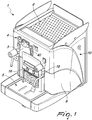
- the machine for dispensing infused beverages and the like particularly of the type with capsules and/or pods, designated generally by the reference numeral 1, comprises a supporting frame 2 enclosed within an external case constituted by a front panel 3, which is provided with the control elements 4 and forms the worktop 5 of the dispensing machine 1, an upper lid 6, which forms a resting surface for cups or others, a rear panel 7 and two side panels 8 and 9, one of which is provided with a door 10 adapted to allow access to the tank 11 of the dispensing machine 1 that is adapted to contain the water required to obtain an infusion or the like.
- the infusion assembly 12 comprises at least two infusion chambers 16 and 17, respectively a left one and a right one if viewed from the front, which are mutually separate and are each provided with a dispensing spout 18 and are adapted to accommodate at least two separate capsules and/or pods 13.
- the two infusion chambers 16 and 17 are functionally connected to the electric pump 15 by means of at least one electric valve 19 with at least three ways.
- means 20 are comprised for controlling the flow of the water that arrives from the electric valve 19 in the direction of at least one of the two infusion chambers 16 and 17, and means 21 are comprised for detecting the capsules and/or pods 13 accommodated in the two infusion chambers 16 and 17 for either the activation or the deactivation of the flow control means 20 mentioned earlier.
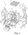
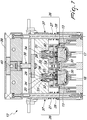
- the infusion assembly 12 comprises a main body 22 which is integrally associated with the supporting frame 2 and at least one slider 23, which is provided with a lid 24 provided with a grip handle, which is slidingly associated with the main body 22 along a substantially horizontal direction 25 with respect to the spatial orientation of the dispensing machine 1 in its normal use.
- the slider 23 can move, along the substantially horizontal direction 25, between a position that is partially internal to the main body 22 and corresponds to the closed state of the infusion assembly 12 shown in Figure 1 , and a position that exits from the main body 22 and corresponds to the open state of the infusion assembly 12 shown in Figure 2 , so as to protrude outside the general volume of the dispensing machine 1 and allow the placement of the capsules and/or pods 13 in the slider 23.
- the main body 22 and the slider 23 are shaped so as to form, once they are mutually coupled in said partially internal position of the slider 23, the two infusion chambers 16 and 17.
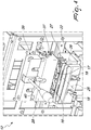
- the infusion assembly 12 comprises, for each infusion chamber 16 and 17, a dispensing piston 26, which is arranged above the respective infusion chamber 16 and 17 with which it is associated and can move in contrast with first elastic means 27 along a direction 28 that is substantially normal to the plane of arrangement of the capsule and/or pod 13 accommodated in the respective infusion chamber 16 and 17, from an inactive position, in which each dispensing piston 26 is spaced from the respective infusion chamber 16 and 17 so as to allow the movement of the slider 23 along the substantially horizontal direction 25, to an active position, which each dispensing piston 26 abuts against the respective infusion chamber 16 and 17 so as to seal it hermetically, and vice versa due to the elastic return of the first elastic means 27.
- the dispensing pistons 26 are shaped so that each one forms inside it a supply channel 29 which is adapted to connect the electric valve 19 to the two infusion chambers 16 and 17.
- the previously mentioned detection means 21 comprise, for each one of the dispensing pistons 26, a plunger that is substantially T-shaped and is formed by a perforated plate 30, which can be arranged so as to face the respective infusion chamber 16 or 17, and a stem 31, which is accommodated slidingly with play inside and along the respective supply channel 29.
- said supply channels 29 are formed inside the dispensing pistons 26 centrally thereto and in a manner that is parallel to the substantially normal direction 28 and the plungers can move in contrast with second elastic means 32 along the substantially normal direction 28 from a detection position, in which each plunger protrudes from the respective dispensing piston 26 in the direction of the respective infusion chamber 16 or 17, so that the respective perforated plate 30 is accommodated in the respective infusion chamber 16 or 17, to a detected position, in which each plunger is retracted into the respective dispensing piston 26 as a consequence of the contrast with the capsule and/or pod 13 accommodated in the respective infusion chamber 16 or 17 in the transition of the dispensing pistons 26 from the inactive position to the active position.
- the second elastic means 32 are interposed between the perforated plates 30 and first contrast surfaces 33 formed by the dispensing pistons 26 on the opposite side with respect to the infusion chambers 16 and 17 relative to the perforated plates 30.
- the stems 31 each comprise a radially widened portion 34, which is arranged on the opposite side with respect to the perforated plates 30 and is adapted to act as a stroke limiter of a mechanical type against second contrast surfaces 35 formed by the dispensing pistons 26 on the opposite side with respect to the first contrast surfaces 33 in the transition from the detected position to the detection position.
- the flow control means 20 consist of hydraulic sealing elements which are associated with at least one of the dispensing pistons 26 and are arranged inside the respective supply channel 29 so as to affect the flow of the water that arrives from the electric valve 19 toward the respective infusion chamber 16 or 17 when the dispensing pistons 26 are arranged in their active position in the absence of the capsule and/or pod 13.
- said flow control means 20 are provided only at a single infusion chamber 16 in order to allow the water to flow into the other infusion chamber 17 even in the absence of the capsules or pods 13 and thus allow the washing of the infusion chamber 17.
- the flow control means 20 comprise an annular gasket 36 that is fitted on at least one of the stems 31 at the radially widened portion 34 so as to be interposed between it and the respective second contrast surface 35.
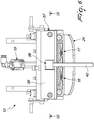
- the infusion assembly 12 comprises at least one heat exchanger 37 which is associated directly with the electric valve 19 and forms inside it the channels for the passage of the water intended for the two infusion chambers 16 and 17, which supports the dispensing pistons 26 and is slidingly associated with the main body 22 by means of two guided posts 38 which are oriented so as to be parallel to the substantially normal direction 28 so that the dispensing pistons 26 are arranged above the main body 22.
- the first elastic means 27 are formed along the guided posts 38 in a manner which is interposed between the heat exchanger 37 and the main body 22.
- the movement of the heat exchanger 37 is provided by means of a crank system 38 which is interposed between the heat exchanger 37 and a fixed part 39 of the supporting frame 2, the movement of which is provided by means of a manually actuated control lever 40.
- the machine for dispensing infused beverages and the like particularly of the type with capsules and/or pods, according to the present invention, achieves the intended aim and objects, since it allows to dispense at will one or two beverages even of different flavor, without duplicating the main components of the machine but only by providing a multiple infusion assembly.
- Another advantage of the dispensing machine according to the present invention resides in that it is possible to perform washing operations when needed on at least one infusion chamber.
- possible variations of the dispensing machine according to the invention might provide an infusion assembly with more than two infusion chambers, such as to allow the dispensing of more than two beverages simultaneously without having to duplicate the components of the machine, or the application of multiple infusion assemblies on a multiple dispensing machine might be provided so as to be able to dispense more than two beverages simultaneously without abandoning the inventive concept of the present invention.
- the materials used may be any according to the requirements and the state of the art.
Landscapes
- Engineering & Computer Science (AREA)
- Food Science & Technology (AREA)
- Mechanical Engineering (AREA)
- Apparatus For Making Beverages (AREA)
- General Preparation And Processing Of Foods (AREA)
- Medicinal Preparation (AREA)
Claims (7)
- Eine Maschine (1) zur Abgabe von Aufgussgetränken und dergleichen, insbesondere von der Art mit Kapseln und/oder Hülsen, die einen tragenden Rahmen (2) umfasst, welcher Folgendes enthält:- mindestens einen Tank (11), ausgebildet, um das Wasser aufzunehmen, das benötigt wird, um einen Aufguss oder dergleichen zu erhalten;- mindestens einen Aufgussaufbau (12), der funktionell mit dem mindestens einen Tank (11) verbunden und ausgebildet ist, um den Aufguss von Kapseln und/oder Hülsen (13) durchzuführen, die in ihm enthalten sind;- mindestens einen Boiler (14), der funktionell zwischen dem mindestens einen Tank (11) und dem mindestens einen Aufgussaufbau (12) angeordnet ist, um das Wasser zu erhitzen, das für den mindestens einen Aufgussaufbau (12) bestimmt ist, und- mindestens eine elektrische Pumpe (15), die zwischen dem mindestens einen Aufgussaufbau (12) und dem mindestens einen Boiler (14) angeordnet ist, zum Pumpen von Wasser aus dem mindestens einen Boiler (14) zu dem mindestens einen Aufgussaufbau (12),wobei der mindestens eine Aufgussaufbau (12) mindestens zwei voneinander getrennte Aufgusskammern (16, 17) umfasst, die jeweils mit einer Abgabedüse (18) ausgestattet und ausgebildet sind, um mindestens zwei separate Kapseln und/oder Hülsen (13) aufzunehmen, wobei die mindestens zwei Aufgusskammern (16, 17) funktionell über mindestens ein elektrisches Ventil (19) mit mindestens drei Wegen mit der mindestens einen elektrischen Pumpe (15) verbunden sind, wobei weiter Mittel (20) umfasst sind, um den Strom des Wassers, das von dem mindestens einen elektrischen Ventil (19) kommt, in Richtung mindestens einer der mindestens zwei Aufgusskammern (16, 17) zu steuern, und wobei Mittel (21) umfasst sind, um die Kapseln und/oder Hülsen (13) zu erkennen, die in die mindestens zwei Aufgusskammern (16, 17) aufgenommen sind, zur Aktivierung oder Deaktivierung der Durchflussregelungsmittel (20), wobei der mindestens eine Aufgussaufbau (12) einen Hauptkörper (22) umfasst, welcher integral mit dem tragenden Rahmen (2) verbunden ist, und mindestens einen Schieber (23), der verschiebbar mit dem Hauptkörper (22) entlang einer Richtung (25) verbunden ist, die im Wesentlichen horizontal zur räumlichen Ausrichtung der Abgabemaschine (1) in ihrem normalen Gebrauch ist, wobei der mindestens eine Schieber (23) in der im Wesentlichen horizontalen Richtung (25) zwischen einer Position, die teilweise innerhalb des Hauptkörpers (22) liegt, und einer Position beweglich ist, die aus dem Hauptkörper (22) heraustritt, um aus dem allgemeinen Volumen der Abgabemaschine (1) herauszuragen und die Positionierung der Kapseln und/oder Hülsen (13) in den mindestens einen Schieber (23) zu ermöglichen, wobei der Hauptkörper (22) und der mindestens eine Schieber (23) geformt sind, um, sobald sie miteinander in der teilweise internen Position des mindestens einen Schiebers (23) gekoppelt wurden, die mindestens zwei Aufgusskammern (16, 17) zu bestimmen, wobei der Aufgussaufbau (12) für jede der mindestens zwei Aufgusskammern (16, 17) einen Abgabekolben (26) umfasst, der oberhalb der jeweiligen der mindestens zwei Aufgusskammern (16, 17) angeordnet ist, mit der er verbunden ist, und beweglich im Kontrast zu ersten elastischen Mitteln (27) in einer Richtung, die im Wesentlichen normal (28) zur Anordnungsebene der Kapsel und/oder Hülse (13) ist, die in der entsprechenden Aufgusskammer (16, 17) angeordnet ist, aus einer inaktiven Position, in welcher der Abgabekolben (26) von der jeweiligen Aufgusskammer (16, 17) beabstandet ist, um die Bewegung des mindestens einen Schiebers (23) zu ermöglichen, in eine aktive Position, in welcher der Abgabekolben (26) an die jeweilige Aufgusskammer (16, 17) anstößt, um sie hermetisch abzudichten, und umgekehrt, aufgrund der elastischen Rückstellung der ersten elastischen Mittel (27), wobei die Abgabekolben (26) so geformt sind, dass jeder in seinem Inneren einen Zuführkanal (29) bildet, der ausgebildet ist, um das mindestens eine elektrische Ventil (19) mit den mindestens zwei Aufgusskammern (16, 17) zu verbinden, wobei die Erkennungsmittel (21) für jeden der Abgabekolben (26) einen Plunger umfassen, der im Wesentlichen T-förmig ist und von einer perforierten Platte (30) gebildet wird, die so angeordnet werden kann, dass sie der jeweiligen der mindestens zwei Aufgusskammern (16, 17) zugewandt ist, und einen Schaft (31), der verschiebbar mit Spiel innerhalb und entlang des jeweiligen der Zuführkanäle (29) aufgenommen ist, wobei die Zuführkanäle (29) zentral innerhalb der Abgabekolben (26) und auf eine Art geformt sind, die parallel zu der im Wesentlichen normalen Richtung (28) ist, und wobei die Plunger in der im Wesentlichen normalen Richtung (28) im Kontrast zu zweiten elastischen Mitteln (32) beweglich sind aus einer Erkennungsposition, in welcher jeder der Plunger aus dem jeweiligen der Abgabekolben (26) in Richtung der entsprechenden der mindestens zwei Aufgusskammern (16, 17) herausragt, so dass die jeweilige der perforierten Platten (30) in die jeweilige Aufgusskammer (16, 17) aufgenommen ist, in eine erkannte Position, in welcher jeder der Plunger in den jeweiligen Abgabekolben (26) infolge des Kontrasts zu der Kapsel und/oder Hülse (13) zurückgezogen ist, die in die jeweilige Aufgusskammer (16, 17) aufgenommen ist, beim Übergang der Abgabekolben (26) aus der inaktiven Position in die aktive Position und umgekehrt aufgrund der elastischen Rückstellung der zweiten elastischen Mittel (32) beim Übergang der Abgabekolben (26) aus der aktiven Position in die inaktive Position, wobei die zweiten elastischen Mittel (32) zwischen den perforierten Platten (30) und ersten Kontrastoberflächen (33) angeordnet sind, die von den Abgabekolben (26) auf der Seite gebildet sind, die den mindestens zwei Aufgusskammern (16, 17) relativ zu den perforierten Platten (30) gegenüberliegt, wobei die Schäfte (31) weiter jeweils einen radial erweiterten Abschnitt (34) umfassen, der auf der gegenüberliegenden Seite mit Bezug auf die perforierten Platten (30) angeordnet und ausgebildet ist, um als Hubbegrenzer des mechanischen Typs gegen zweite Kontrastoberflächen (35) zu wirken, die von den Abgabekolben (26) auf der gegenüberliegenden Seite mit Bezug auf die ersten Kontrastoberflächen (33) gebildet sind, beim Übergang aus der erkannten Position in die Erkennungsposition.
- Die Abgabemaschine (1) gemäß Anspruch 1, dadurch gekennzeichnet, dass die Durchflussregelungsmittel (20) aus hydraulischen Abdichtungselementen bestehen, die mit mindestens einem der Abgabekolben (26) verbunden und innerhalb des jeweiligen der Zuführkanäle (29) angeordnet sind, um den Strom von Wasser zu beeinflussen, der von dem mindestens einen elektrischen Ventil (19) zu der entsprechenden der mindestens zwei Aufgusskammern (16, 17) strömt, wenn die Abgabekolben (26) in Abwesenheit der Kapsel und/oder Hülse (13) in der aktiven Position angeordnet sind.
- Die Abgabemaschine (1) gemäß Anspruch 2, dadurch gekennzeichnet, dass die Durchflussregelungsmittel (20) nur an einer der mindestens zwei Aufgusskammern (16) angebracht sind, um zu ermöglichen, dass das Wasser selbst in Abwesenheit der Kapseln oder Hülsen (13) in die andere der mindestens zwei Aufgusskammern (17) strömt.
- Die Abgabemaschine (1) gemäß Anspruch 2 oder 3, dadurch gekennzeichnet, dass die Durchflussregelungsmittel (20) einen Dichtring (36) umfassen, der auf mindestens einen der Schäfte (31) an dem radial erweiterten Abschnitt (34) aufgesetzt ist, um zwischen dem radial erweiterten Abschnitt (34) und der entsprechenden der zweiten Kontrastoberflächen (35) angeordnet zu sein.
- Die Abgabemaschine (1) gemäß einem oder mehreren der obigen Ansprüche, dadurch gekennzeichnet, dass der mindestens eine Aufgussaufbau (12) mindestens einen Wärmetauscher (37) umfasst, der direkt mit dem mindestens einen elektrischen Ventil (19) verbunden ist und in dem die Kanäle für den Durchfluss des Wassers gebildet sind, das für die mindestens zwei Aufgusskammern (16, 17) bestimmt ist, der die Abgabekolben (26) trägt und verschiebbar mit dem Hauptkörper (22) über zwei geführte Stützen (38) verbunden ist, die parallel zu der im Wesentlichen normalen Richtung (28) ausgerichtet sind, so dass die Abgabekolben (26) oberhalb des Hauptkörpers (22) angeordnet sind, wobei sich entlang den geführten Stützen (38) die ersten elastischen Mittel (27) befinden, auf eine Art, die zwischen dem mindestens einen Wärmetauscher (37) und dem Hauptkörper (22) angeordnet ist.
- Die Abgabemaschine (1) gemäß Anspruch 5, dadurch gekennzeichnet, dass die Bewegung des mindestens eines Wärmetauschers (37) mittels eines Kurbelsystems (38) durchgeführt wird, welches zwischen dem Wärmetauscher (37) und einem festen Teil (39) des tragenden Rahmens (2) angeordnet ist.
- Die Abgabemaschine (1) gemäß Anspruch 6, dadurch gekennzeichnet, dass die Bewegung des Kurbelsystems (38) mit Hilfe eines manuell betätigten Betätigungshebels (40) durchgeführt wird.
Priority Applications (1)
| Application Number | Priority Date | Filing Date | Title |
|---|---|---|---|
| PL19189416T PL3603462T3 (pl) | 2018-08-01 | 2019-07-31 | Urządzenie do dozowania zaparzanych napojów i tym podobnych, w szczególności rodzaju z kapsułkami i/lub zasobnikami |
Applications Claiming Priority (1)
| Application Number | Priority Date | Filing Date | Title |
|---|---|---|---|
| IT102018000007714A IT201800007714A1 (it) | 2018-08-01 | 2018-08-01 | Macchina erogatrice di bevande infuse e simili, particolarmente del tipo a capsule e/o cialde. |
Publications (2)
| Publication Number | Publication Date |
|---|---|
| EP3603462A1 EP3603462A1 (de) | 2020-02-05 |
| EP3603462B1 true EP3603462B1 (de) | 2021-02-17 |
Family
ID=63840939
Family Applications (1)
| Application Number | Title | Priority Date | Filing Date |
|---|---|---|---|
| EP19189416.1A Active EP3603462B1 (de) | 2018-08-01 | 2019-07-31 | Maschine zur abgabe von aufgussgetränken und dergleichen, insbesondere von der art mit kapseln und/oder hülsen |
Country Status (6)
| Country | Link |
|---|---|
| EP (1) | EP3603462B1 (de) |
| DK (1) | DK3603462T3 (de) |
| ES (1) | ES2869452T3 (de) |
| IT (1) | IT201800007714A1 (de) |
| PL (1) | PL3603462T3 (de) |
| PT (1) | PT3603462T (de) |
Families Citing this family (1)
| Publication number | Priority date | Publication date | Assignee | Title |
|---|---|---|---|---|
| US12053117B1 (en) * | 2023-05-05 | 2024-08-06 | Starbucks Corporation | Systems, methods, and devices, for parallel extraction of beverages |
Family Cites Families (7)
| Publication number | Priority date | Publication date | Assignee | Title |
|---|---|---|---|---|
| JP3891356B2 (ja) * | 2002-01-10 | 2007-03-14 | ソシエテ・デ・プロデュイ・ネスレ・エス・アー | 物質を抽出するための自動抽出装置 |
| FR2849760B1 (fr) * | 2003-01-15 | 2005-08-26 | Unic | Dispositif et machine pour l'extraction d'une substance pour la production de boisson |
| FR2873011B1 (fr) * | 2004-07-16 | 2007-12-14 | Reneka Internat Sarl | Groupe de preparation d'au moins une tasse de cafe de type expresso ou autre boisson chaude a partir d'une dose individuelle preemballee appelee dosette |
| DE202007002910U1 (de) * | 2007-02-26 | 2007-05-10 | Mahlich, Gotthard | Brüheinheit eines Getränkezubereitungsgeräts |
| IT1398521B1 (it) * | 2010-02-17 | 2013-03-01 | Illycaffe Spa | Dispositivo erogatore per macchine per la preparazione di bevande, particolarmente per la produzione di caffe' espresso. |
| ITUB20150258A1 (it) * | 2015-02-25 | 2016-08-25 | La Marzocco Srl | Gruppo di erogazione di acqua calda per una macchina per caffè espresso o simile e relativa macchina |
| CH710945A1 (de) * | 2015-04-08 | 2016-10-14 | Delica Ag | Getränkezubereitungsmaschine. |
-
2018
- 2018-08-01 IT IT102018000007714A patent/IT201800007714A1/it unknown
-
2019
- 2019-07-31 ES ES19189416T patent/ES2869452T3/es active Active
- 2019-07-31 PL PL19189416T patent/PL3603462T3/pl unknown
- 2019-07-31 DK DK19189416.1T patent/DK3603462T3/da active
- 2019-07-31 PT PT191894161T patent/PT3603462T/pt unknown
- 2019-07-31 EP EP19189416.1A patent/EP3603462B1/de active Active
Non-Patent Citations (1)
| Title |
|---|
| None * |
Also Published As
| Publication number | Publication date |
|---|---|
| PT3603462T (pt) | 2021-05-17 |
| IT201800007714A1 (it) | 2020-02-01 |
| PL3603462T3 (pl) | 2021-08-16 |
| ES2869452T3 (es) | 2021-10-25 |
| DK3603462T3 (da) | 2021-05-10 |
| EP3603462A1 (de) | 2020-02-05 |
Similar Documents
| Publication | Publication Date | Title |
|---|---|---|
| EP2356928B1 (de) | Adapter für Getränkezubereitungsmaschinen, insbesondere zur Zubereitung von Espresso | |
| EP2515727B1 (de) | Aufgusseinheit für getränke mit waschsystem | |
| EP2515726B1 (de) | Aufgusseinheit für getränke mit hydraulischem verschlusssystem | |
| US9364115B2 (en) | Brewing unit for preparation of beverages, and machine comprising said brewing unit | |
| US10561266B2 (en) | Brewing unit | |
| US6481338B1 (en) | Spoon shaped coffee brewing apparatus | |
| US11103101B2 (en) | System for preparing aromatic beverages with optmized beverage discharge disposition and process of operation of said system | |
| US7784396B2 (en) | Hydraulic sealing assembly for a beverage machine brewing head | |
| EP2656755B1 (de) | Infustionsgruppe | |
| EP3057478A1 (de) | Vorrichtung zum einsetzen eines filterhalters in einen kaffeespender | |
| EP3603462B1 (de) | Maschine zur abgabe von aufgussgetränken und dergleichen, insbesondere von der art mit kapseln und/oder hülsen | |
| US20230034233A1 (en) | Coffee machine, closing and/or tamping system and valve arrangement suitable for use in a coffee machine | |
| EP2783609A1 (de) | Druckentlastungsventil | |
| USD898510S1 (en) | Water container for beer brewing machine | |
| HK1244647A1 (en) | Machine for making beverages | |
| ITTO20090646A1 (it) | Sistema, capsula, macchina percolatrice e metodo per la preparazione di una bevanda per infusione a concentrazione selezionabile dall'utente | |
| EP3139797B1 (de) | Automat zum zubereiten von kaffee | |
| CN202128317U (zh) | 饮料机 | |
| US20180289199A1 (en) | Turkish coffee machine | |
| US20240285112A1 (en) | Machine for cooking food in a container | |
| IT202100014012A1 (it) | Gruppo erogatore per macchine per la preparazione di bevande a capsule | |
| ITUA20164670A1 (it) | Gruppo di infusione per macchine per il caffè, ad elevata versatilità di impiego. | |
| HK1157159B (en) | Adapter for beverage preparation machines, particularly for making espresso coffee | |
| ITUB20155523A1 (it) | Dispositivo per l?erogazione di gelato e relativo metodo di erogazione | |
| HK1240476A1 (en) | Infusion group for machines for the dispensing of beverages in the form of infusion |
Legal Events
| Date | Code | Title | Description |
|---|---|---|---|
| PUAI | Public reference made under article 153(3) epc to a published international application that has entered the european phase |
Free format text: ORIGINAL CODE: 0009012 |
|
| STAA | Information on the status of an ep patent application or granted ep patent |
Free format text: STATUS: THE APPLICATION HAS BEEN PUBLISHED |
|
| AK | Designated contracting states |
Kind code of ref document: A1 Designated state(s): AL AT BE BG CH CY CZ DE DK EE ES FI FR GB GR HR HU IE IS IT LI LT LU LV MC MK MT NL NO PL PT RO RS SE SI SK SM TR |
|
| AX | Request for extension of the european patent |
Extension state: BA ME |
|
| STAA | Information on the status of an ep patent application or granted ep patent |
Free format text: STATUS: REQUEST FOR EXAMINATION WAS MADE |
|
| 17P | Request for examination filed |
Effective date: 20200406 |
|
| RBV | Designated contracting states (corrected) |
Designated state(s): AL AT BE BG CH CY CZ DE DK EE ES FI FR GB GR HR HU IE IS IT LI LT LU LV MC MK MT NL NO PL PT RO RS SE SI SK SM TR |
|
| RIC1 | Information provided on ipc code assigned before grant |
Ipc: A47J 31/46 20060101ALI20200714BHEP Ipc: A47J 31/36 20060101AFI20200714BHEP |
|
| GRAP | Despatch of communication of intention to grant a patent |
Free format text: ORIGINAL CODE: EPIDOSNIGR1 |
|
| STAA | Information on the status of an ep patent application or granted ep patent |
Free format text: STATUS: GRANT OF PATENT IS INTENDED |
|
| INTG | Intention to grant announced |
Effective date: 20200904 |
|
| GRAS | Grant fee paid |
Free format text: ORIGINAL CODE: EPIDOSNIGR3 |
|
| GRAA | (expected) grant |
Free format text: ORIGINAL CODE: 0009210 |
|
| STAA | Information on the status of an ep patent application or granted ep patent |
Free format text: STATUS: THE PATENT HAS BEEN GRANTED |
|
| AK | Designated contracting states |
Kind code of ref document: B1 Designated state(s): AL AT BE BG CH CY CZ DE DK EE ES FI FR GB GR HR HU IE IS IT LI LT LU LV MC MK MT NL NO PL PT RO RS SE SI SK SM TR |
|
| REG | Reference to a national code |
Ref country code: GB Ref legal event code: FG4D |
|
| REG | Reference to a national code |
Ref country code: CH Ref legal event code: EP |
|
| REG | Reference to a national code |
Ref country code: DE Ref legal event code: R096 Ref document number: 602019002574 Country of ref document: DE |
|
| REG | Reference to a national code |
Ref country code: AT Ref legal event code: REF Ref document number: 1360316 Country of ref document: AT Kind code of ref document: T Effective date: 20210315 |
|
| REG | Reference to a national code |
Ref country code: IE Ref legal event code: FG4D |
|
| REG | Reference to a national code |
Ref country code: CH Ref legal event code: NV Representative=s name: LUMI IP GMBH, CH |
|
| REG | Reference to a national code |
Ref country code: NL Ref legal event code: FP |
|
| REG | Reference to a national code |
Ref country code: RO Ref legal event code: EPE Ref country code: DK Ref legal event code: T3 Effective date: 20210507 |
|
| REG | Reference to a national code |
Ref country code: PT Ref legal event code: SC4A Ref document number: 3603462 Country of ref document: PT Date of ref document: 20210517 Kind code of ref document: T Free format text: AVAILABILITY OF NATIONAL TRANSLATION Effective date: 20210510 |
|
| REG | Reference to a national code |
Ref country code: GR Ref legal event code: EP Ref document number: 20210401030 Country of ref document: GR Effective date: 20210614 |
|
| REG | Reference to a national code |
Ref country code: LT Ref legal event code: MG9D |
|
| REG | Reference to a national code |
Ref country code: AT Ref legal event code: UEP Ref document number: 1360316 Country of ref document: AT Kind code of ref document: T Effective date: 20210217 |
|
| PG25 | Lapsed in a contracting state [announced via postgrant information from national office to epo] |
Ref country code: LT Free format text: LAPSE BECAUSE OF FAILURE TO SUBMIT A TRANSLATION OF THE DESCRIPTION OR TO PAY THE FEE WITHIN THE PRESCRIBED TIME-LIMIT Effective date: 20210217 Ref country code: NO Free format text: LAPSE BECAUSE OF FAILURE TO SUBMIT A TRANSLATION OF THE DESCRIPTION OR TO PAY THE FEE WITHIN THE PRESCRIBED TIME-LIMIT Effective date: 20210517 Ref country code: FI Free format text: LAPSE BECAUSE OF FAILURE TO SUBMIT A TRANSLATION OF THE DESCRIPTION OR TO PAY THE FEE WITHIN THE PRESCRIBED TIME-LIMIT Effective date: 20210217 Ref country code: HR Free format text: LAPSE BECAUSE OF FAILURE TO SUBMIT A TRANSLATION OF THE DESCRIPTION OR TO PAY THE FEE WITHIN THE PRESCRIBED TIME-LIMIT Effective date: 20210217 |
|
| PGFP | Annual fee paid to national office [announced via postgrant information from national office to epo] |
Ref country code: RO Payment date: 20210512 Year of fee payment: 3 |
|
| PG25 | Lapsed in a contracting state [announced via postgrant information from national office to epo] |
Ref country code: LV Free format text: LAPSE BECAUSE OF FAILURE TO SUBMIT A TRANSLATION OF THE DESCRIPTION OR TO PAY THE FEE WITHIN THE PRESCRIBED TIME-LIMIT Effective date: 20210217 Ref country code: SE Free format text: LAPSE BECAUSE OF FAILURE TO SUBMIT A TRANSLATION OF THE DESCRIPTION OR TO PAY THE FEE WITHIN THE PRESCRIBED TIME-LIMIT Effective date: 20210217 Ref country code: RS Free format text: LAPSE BECAUSE OF FAILURE TO SUBMIT A TRANSLATION OF THE DESCRIPTION OR TO PAY THE FEE WITHIN THE PRESCRIBED TIME-LIMIT Effective date: 20210217 |
|
| PGFP | Annual fee paid to national office [announced via postgrant information from national office to epo] |
Ref country code: BG Payment date: 20210518 Year of fee payment: 3 |
|
| PG25 | Lapsed in a contracting state [announced via postgrant information from national office to epo] |
Ref country code: IS Free format text: LAPSE BECAUSE OF FAILURE TO SUBMIT A TRANSLATION OF THE DESCRIPTION OR TO PAY THE FEE WITHIN THE PRESCRIBED TIME-LIMIT Effective date: 20210617 |
|
| REG | Reference to a national code |
Ref country code: ES Ref legal event code: FG2A Ref document number: 2869452 Country of ref document: ES Kind code of ref document: T3 Effective date: 20211025 |
|
| PG25 | Lapsed in a contracting state [announced via postgrant information from national office to epo] |
Ref country code: EE Free format text: LAPSE BECAUSE OF FAILURE TO SUBMIT A TRANSLATION OF THE DESCRIPTION OR TO PAY THE FEE WITHIN THE PRESCRIBED TIME-LIMIT Effective date: 20210217 Ref country code: CZ Free format text: LAPSE BECAUSE OF FAILURE TO SUBMIT A TRANSLATION OF THE DESCRIPTION OR TO PAY THE FEE WITHIN THE PRESCRIBED TIME-LIMIT Effective date: 20210217 Ref country code: SM Free format text: LAPSE BECAUSE OF FAILURE TO SUBMIT A TRANSLATION OF THE DESCRIPTION OR TO PAY THE FEE WITHIN THE PRESCRIBED TIME-LIMIT Effective date: 20210217 |
|
| REG | Reference to a national code |
Ref country code: DE Ref legal event code: R097 Ref document number: 602019002574 Country of ref document: DE |
|
| PG25 | Lapsed in a contracting state [announced via postgrant information from national office to epo] |
Ref country code: SK Free format text: LAPSE BECAUSE OF FAILURE TO SUBMIT A TRANSLATION OF THE DESCRIPTION OR TO PAY THE FEE WITHIN THE PRESCRIBED TIME-LIMIT Effective date: 20210217 |
|
| PGFP | Annual fee paid to national office [announced via postgrant information from national office to epo] |
Ref country code: TR Payment date: 20210702 Year of fee payment: 3 |
|
| PLBE | No opposition filed within time limit |
Free format text: ORIGINAL CODE: 0009261 |
|
| STAA | Information on the status of an ep patent application or granted ep patent |
Free format text: STATUS: NO OPPOSITION FILED WITHIN TIME LIMIT |
|
| 26N | No opposition filed |
Effective date: 20211118 |
|
| PG25 | Lapsed in a contracting state [announced via postgrant information from national office to epo] |
Ref country code: AL Free format text: LAPSE BECAUSE OF FAILURE TO SUBMIT A TRANSLATION OF THE DESCRIPTION OR TO PAY THE FEE WITHIN THE PRESCRIBED TIME-LIMIT Effective date: 20210217 |
|
| PG25 | Lapsed in a contracting state [announced via postgrant information from national office to epo] |
Ref country code: SI Free format text: LAPSE BECAUSE OF FAILURE TO SUBMIT A TRANSLATION OF THE DESCRIPTION OR TO PAY THE FEE WITHIN THE PRESCRIBED TIME-LIMIT Effective date: 20210217 |
|
| PG25 | Lapsed in a contracting state [announced via postgrant information from national office to epo] |
Ref country code: MC Free format text: LAPSE BECAUSE OF FAILURE TO SUBMIT A TRANSLATION OF THE DESCRIPTION OR TO PAY THE FEE WITHIN THE PRESCRIBED TIME-LIMIT Effective date: 20210217 |
|
| PG25 | Lapsed in a contracting state [announced via postgrant information from national office to epo] |
Ref country code: IS Free format text: LAPSE BECAUSE OF FAILURE TO SUBMIT A TRANSLATION OF THE DESCRIPTION OR TO PAY THE FEE WITHIN THE PRESCRIBED TIME-LIMIT Effective date: 20210617 Ref country code: LU Free format text: LAPSE BECAUSE OF NON-PAYMENT OF DUE FEES Effective date: 20210731 |
|
| PG25 | Lapsed in a contracting state [announced via postgrant information from national office to epo] |
Ref country code: IE Free format text: LAPSE BECAUSE OF NON-PAYMENT OF DUE FEES Effective date: 20210731 |
|
| PGFP | Annual fee paid to national office [announced via postgrant information from national office to epo] |
Ref country code: IT Payment date: 20220801 Year of fee payment: 4 |
|
| REG | Reference to a national code |
Ref country code: CH Ref legal event code: PL |
|
| PG25 | Lapsed in a contracting state [announced via postgrant information from national office to epo] |
Ref country code: RO Free format text: LAPSE BECAUSE OF NON-PAYMENT OF DUE FEES Effective date: 20220731 Ref country code: LI Free format text: LAPSE BECAUSE OF NON-PAYMENT OF DUE FEES Effective date: 20220731 Ref country code: CH Free format text: LAPSE BECAUSE OF NON-PAYMENT OF DUE FEES Effective date: 20220731 |
|
| PG25 | Lapsed in a contracting state [announced via postgrant information from national office to epo] |
Ref country code: CY Free format text: LAPSE BECAUSE OF FAILURE TO SUBMIT A TRANSLATION OF THE DESCRIPTION OR TO PAY THE FEE WITHIN THE PRESCRIBED TIME-LIMIT Effective date: 20210217 |
|
| PG25 | Lapsed in a contracting state [announced via postgrant information from national office to epo] |
Ref country code: HU Free format text: LAPSE BECAUSE OF FAILURE TO SUBMIT A TRANSLATION OF THE DESCRIPTION OR TO PAY THE FEE WITHIN THE PRESCRIBED TIME-LIMIT; INVALID AB INITIO Effective date: 20190731 |
|
| PG25 | Lapsed in a contracting state [announced via postgrant information from national office to epo] |
Ref country code: MK Free format text: LAPSE BECAUSE OF FAILURE TO SUBMIT A TRANSLATION OF THE DESCRIPTION OR TO PAY THE FEE WITHIN THE PRESCRIBED TIME-LIMIT Effective date: 20210217 |
|
| PG25 | Lapsed in a contracting state [announced via postgrant information from national office to epo] |
Ref country code: IT Free format text: LAPSE BECAUSE OF NON-PAYMENT OF DUE FEES Effective date: 20230731 Ref country code: BG Free format text: LAPSE BECAUSE OF NON-PAYMENT OF DUE FEES Effective date: 20220731 |
|
| PG25 | Lapsed in a contracting state [announced via postgrant information from national office to epo] |
Ref country code: MT Free format text: LAPSE BECAUSE OF FAILURE TO SUBMIT A TRANSLATION OF THE DESCRIPTION OR TO PAY THE FEE WITHIN THE PRESCRIBED TIME-LIMIT Effective date: 20210217 |
|
| PGFP | Annual fee paid to national office [announced via postgrant information from national office to epo] |
Ref country code: DK Payment date: 20250127 Year of fee payment: 6 |
|
| PGFP | Annual fee paid to national office [announced via postgrant information from national office to epo] |
Ref country code: AT Payment date: 20250130 Year of fee payment: 6 |
|
| PGFP | Annual fee paid to national office [announced via postgrant information from national office to epo] |
Ref country code: NL Payment date: 20250731 Year of fee payment: 7 |
|
| PGFP | Annual fee paid to national office [announced via postgrant information from national office to epo] |
Ref country code: PT Payment date: 20250731 Year of fee payment: 7 Ref country code: ES Payment date: 20250818 Year of fee payment: 7 |
|
| PGFP | Annual fee paid to national office [announced via postgrant information from national office to epo] |
Ref country code: DE Payment date: 20250821 Year of fee payment: 7 |
|
| PGFP | Annual fee paid to national office [announced via postgrant information from national office to epo] |
Ref country code: GR Payment date: 20250731 Year of fee payment: 7 |
|
| PGFP | Annual fee paid to national office [announced via postgrant information from national office to epo] |
Ref country code: PL Payment date: 20250801 Year of fee payment: 7 |
|
| PGFP | Annual fee paid to national office [announced via postgrant information from national office to epo] |
Ref country code: BE Payment date: 20250731 Year of fee payment: 7 Ref country code: GB Payment date: 20250731 Year of fee payment: 7 |
|
| PGFP | Annual fee paid to national office [announced via postgrant information from national office to epo] |
Ref country code: FR Payment date: 20250731 Year of fee payment: 7 |
|
| REG | Reference to a national code |
Ref country code: DK Ref legal event code: EBP Effective date: 20250731 |