EP3602240B1 - Ultraniedrigleistungsmodus für eine kostengünstige kraftmessvorrichtung - Google Patents
Ultraniedrigleistungsmodus für eine kostengünstige kraftmessvorrichtung Download PDFInfo
- Publication number
- EP3602240B1 EP3602240B1 EP18819298.3A EP18819298A EP3602240B1 EP 3602240 B1 EP3602240 B1 EP 3602240B1 EP 18819298 A EP18819298 A EP 18819298A EP 3602240 B1 EP3602240 B1 EP 3602240B1
- Authority
- EP
- European Patent Office
- Prior art keywords
- microcontroller
- buffer
- low
- gesture
- signal
- Prior art date
- Legal status (The legal status is an assumption and is not a legal conclusion. Google has not performed a legal analysis and makes no representation as to the accuracy of the status listed.)
- Active
Links
Images
Classifications
-
- G—PHYSICS
- G06—COMPUTING OR CALCULATING; COUNTING
- G06F—ELECTRIC DIGITAL DATA PROCESSING
- G06F1/00—Details not covered by groups G06F3/00 - G06F13/00 and G06F21/00
- G06F1/26—Power supply means, e.g. regulation thereof
- G06F1/32—Means for saving power
- G06F1/3203—Power management, i.e. event-based initiation of a power-saving mode
- G06F1/3234—Power saving characterised by the action undertaken
- G06F1/3296—Power saving characterised by the action undertaken by lowering the supply or operating voltage
-
- G—PHYSICS
- G05—CONTROLLING; REGULATING
- G05B—CONTROL OR REGULATING SYSTEMS IN GENERAL; FUNCTIONAL ELEMENTS OF SUCH SYSTEMS; MONITORING OR TESTING ARRANGEMENTS FOR SUCH SYSTEMS OR ELEMENTS
- G05B15/00—Systems controlled by a computer
- G05B15/02—Systems controlled by a computer electric
-
- G—PHYSICS
- G06—COMPUTING OR CALCULATING; COUNTING
- G06F—ELECTRIC DIGITAL DATA PROCESSING
- G06F1/00—Details not covered by groups G06F3/00 - G06F13/00 and G06F21/00
- G06F1/26—Power supply means, e.g. regulation thereof
- G06F1/32—Means for saving power
- G06F1/3203—Power management, i.e. event-based initiation of a power-saving mode
- G06F1/3206—Monitoring of events, devices or parameters that trigger a change in power modality
- G06F1/3231—Monitoring the presence, absence or movement of users
-
- G—PHYSICS
- G06—COMPUTING OR CALCULATING; COUNTING
- G06F—ELECTRIC DIGITAL DATA PROCESSING
- G06F1/00—Details not covered by groups G06F3/00 - G06F13/00 and G06F21/00
- G06F1/26—Power supply means, e.g. regulation thereof
- G06F1/32—Means for saving power
- G06F1/3203—Power management, i.e. event-based initiation of a power-saving mode
- G06F1/3234—Power saving characterised by the action undertaken
- G06F1/3293—Power saving characterised by the action undertaken by switching to a less power-consuming processor, e.g. sub-CPU
-
- G—PHYSICS
- G06—COMPUTING OR CALCULATING; COUNTING
- G06F—ELECTRIC DIGITAL DATA PROCESSING
- G06F1/00—Details not covered by groups G06F3/00 - G06F13/00 and G06F21/00
- G06F1/26—Power supply means, e.g. regulation thereof
- G06F1/32—Means for saving power
- G06F1/3203—Power management, i.e. event-based initiation of a power-saving mode
- G06F1/3234—Power saving characterised by the action undertaken
- G06F1/3287—Power saving characterised by the action undertaken by switching off individual functional units in the computer system
-
- G—PHYSICS
- G06—COMPUTING OR CALCULATING; COUNTING
- G06F—ELECTRIC DIGITAL DATA PROCESSING
- G06F3/00—Input arrangements for transferring data to be processed into a form capable of being handled by the computer; Output arrangements for transferring data from processing unit to output unit, e.g. interface arrangements
- G06F3/01—Input arrangements or combined input and output arrangements for interaction between user and computer
- G06F3/017—Gesture based interaction, e.g. based on a set of recognized hand gestures
-
- Y—GENERAL TAGGING OF NEW TECHNOLOGICAL DEVELOPMENTS; GENERAL TAGGING OF CROSS-SECTIONAL TECHNOLOGIES SPANNING OVER SEVERAL SECTIONS OF THE IPC; TECHNICAL SUBJECTS COVERED BY FORMER USPC CROSS-REFERENCE ART COLLECTIONS [XRACs] AND DIGESTS
- Y02—TECHNOLOGIES OR APPLICATIONS FOR MITIGATION OR ADAPTATION AGAINST CLIMATE CHANGE
- Y02D—CLIMATE CHANGE MITIGATION TECHNOLOGIES IN INFORMATION AND COMMUNICATION TECHNOLOGIES [ICT], I.E. INFORMATION AND COMMUNICATION TECHNOLOGIES AIMING AT THE REDUCTION OF THEIR OWN ENERGY USE
- Y02D10/00—Energy efficient computing, e.g. low power processors, power management or thermal management
Definitions
- Many sensors on computing devices require constant supervision in the form of a program that runs on one or more low-power cores in order to wake the device and enable the device to check for a critical event.
- the low-power core is regularly woken to read data from the sensor to detect an event, many times due to false alarms. For example, some devices sample at a periodic rate of 50 Hz, which results in the low power core waking 50 times per second to read data. This monitoring and waking of the device consumes power, diminishing battery life of the device.
- US2014149854 discloses an electronic device with a processor system.
- sensor management is transferred to a microcontroller connected to at least a portion of the sensors, to save power.
- the microcontroller can analyze the sensor data to determine the likelihood of a wake action being performed.
- the microcontroller makes the processor system go back in an active state, and enables the processor system to resume management of the sensors.
- the invention is defined in the independent claims 1 and 9. Techniques and apparatuses are described that provide an ultra-low power mode for a low-cost force-sensing device. These techniques extend battery life of the device by minimizing power consumption for potential wake-up events. To do this, the device offloads some work to an analog front-end implemented in hardware, which performs basic checks on sensor signals and wakes a microcontroller (e.g., low-power core) only when an "interesting" event occurs with a threshold level of confidence. Then, the microcontroller analyzes the sensor data in more detail. If the microcontroller determines with high confidence that the input signal corresponds to a human gesture, then the microcontroller wakes an application processor (e.g., high-power core) to handle the human gesture.
- a microcontroller e.g., low-power core
- an application processor e.g., high-power core
- the application processor may handle the gesture or return to a sleep mode based on additional criteria.
- a differentiator e.g., high-pass filter
- This differentiator is implemented as part of an autonomous system (e.g., the analog front-end) that provides a preliminary evaluation of the sensor signal before waking the microcontroller to do more analysis.
- the microcontroller is woken to evaluate a set of historical samples, such as 200 or more milliseconds worth of historical data. If a human gesture is not recognized, then the microcontroller returns to an idle state, but if a human gesture is recognized, then the application processor is woken to execute an application configured to perform an operation mapped to the human gesture.
- the plurality of processors include at least a microcontroller and a high-power application processor each configured to be placed in a suspended state (e.g., sleep state).
- the analog front-end is implemented in hardware and configured to convert an analog signal generated by a force sensor into a digital signal, store samples of the digital signal in a buffer, filter the digital signal based on deviations in a rate of change of the signal from a baseline value, and wake the microcontroller from the suspended state responsive to the filtered digital signal passing one or more threshold values.
- the microcontroller is woken to analyze the samples of the digital signal in the buffer to determine whether the digital signal corresponds to a human gesture.
- the microcontroller is configured to wake the high-power application processor from the suspended state to process the human gesture based on the digital signal being recognized as a human gesture.
- a computing device running in a low-power mode still consumes power by constantly monitoring different sensors used to wake the computing device.
- This device may be constantly woken up to read data from the sensors to detect an actual event.
- the event may be a false alarm due to a variety of different factors, such as drift in the sensors.
- Drift can be caused by a variety of different factors, such as mechanical issues caused by material expansion of a component heating non-uniformly, moisture, a relaxation between the sensor and a surface upon which a physical force was applied, and so on.
- Some sensors may not be prone to large amounts of drift, but such sensors can be cost-prohibitive. In contrast, low-cost sensors are generally prone to drift.
- the application processor is not woken but remains in a low-power mode and the microcontroller returns to its low-power mode. In this way, the microcontroller and the application processor are woken fewer times in comparison to conventional techniques that monitor a direct current (DC) threshold and fail to account for drift in the sensors.
- DC direct current
- the smartphone may experience some external forces applied to a housing or case from contact with the user's clothing, or a temperature increase based on the smartphone's proximity to the user's body.
- forces are applied to the housing or case.
- none of these situations represent the user's intent to wake the smartphone, but represent potential false positives that could trigger a wake up event, particularly when using low-cost force sensors that are susceptible to drift.
- the user squeezes the smartphone on opposing sides however, the user's intent may be to trigger a wake up event.
- the techniques and apparatuses described herein reduce the false positives and power consumption by the smartphone when the smartphone is resting in a low-power state because the processor of the smartphone is not required to be awake to operate the force sensors or to verify or reject a potential wake up event.
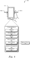
- Fig. 1 illustrates an example environment 100 in which an ultra-low power mode for a low-cost force-sensing device can be implemented.
- Example environment 100 includes a computing device 102 having a sensor(s) 104, an analog front-end 106, a memory 108, a microcontroller(s) 110, and an application processor(s) 112.
- the computing device 102 is configured to run in the ultra-low power mode in which the microcontroller(s) 110 and the application processor(s) 112 are suspended, or placed in a low-power idle state.
- the sensor(s) 104 can include any suitable sensor, such as a force sensor that detects physical force applied to a housing 114 of the computing device.
- the sensor 104 includes a strain gauge, which is integrated on the computing device 102 to mechanically measure strain on the computing device 102, the housing 114, or adhesive between the housing 114 and one or more internal components of the computing device 102.
- Multiple sensor(s) 104 can be implemented on the computing device 102 to detect forces applied to different areas of the computing device 102, such as opposing sides.
- each sensor 104 can be associated with a different integrated circuit (IC) channel, such that data obtained from each sensor 104 can be read independently of data obtained from the other sensors 104.
- IC integrated circuit
- two sensors 104 on opposing sides of the computing device 102 can be associated with a single IC channel to measure a compression force applied to the computing device 102. Accordingly, any suitable sensor 104 can be used to measure force applied to the computing device 102.
- the analog front-end 106 can autonomously determine if data obtained by the sensor(s) 104 warrants waking the microcontroller(s) 110 to analyze the data.
- the analog front-end 106 converts a signal, such as an analog signal, obtained from the sensor(s) 104 into a digital signal.
- the analog front-end 106 also filters the digital signal based on a rate of change of the digital signal relative to a baseline value, and then triggers a wake up event for the microcontroller 110 if the rate of change is above a certain threshold.
- the analog front-end 106 stores raw sensor data in the memory 108, such as in a buffer, to enable the microcontroller 110, once awoken, to perform gesture analysis on the raw sensor data.
- the microcontroller 110 is representative of a low-power computing entity, such as a low-power core directly attached to the analog front-end 106.
- the microcontroller 110 can be woken from the low-power idle state to employ a gesture module 116 to determine whether the raw sensor data corresponds to a human gesture.
- the human gesture includes a squeeze gesture 118 in which a compression force is applied to opposing sides of the housing 114 or cover of the computing device 102, as illustrated by arrows 120-1 and 120-2.
- the example compression force e.g., arrows 120-1, 120-2
- any side e.g., top, bottom, front, back, left side, right side
- any side e.g., top, bottom, front, back, left side, right side
- a human gesture e.g., the squeeze gesture 118
- the microcontroller 110 wakes the application processor 112 to perform an operation associated with the gesture.
- the application processor(s) 112 is representative of a high-power core, such as an ARM processor, capable of running system services and user application code. To conserve power, the application processor(s) 112 remains in the low-power idle state until the microcontroller 110 wakes the application processor(s) 112. Once awoken, the application processor(s) 112 can execute an application 122 to handle the gesture, such as by performing an operation associated with the recognized gesture.
- a high-power core such as an ARM processor
- At least the sensor(s) 104 and the analog front-end 106 are implemented in hardware and can operate autonomously, which allows the microcontroller(s) 110 and the application processor(s) 112 to remain in the low-power idle state for longer periods of time, resulting in a longer battery life.
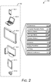
- Fig. 2 illustrates an example implementation 200 of the computing device 102 of Figure 1 in greater detail in accordance with one or more aspects.
- the computing device 102 is illustrated with various non-limiting example devices: smartphone 102-1, laptop 102-2, television 102-3, desktop 102-4, tablet 102-5, and wearable computer 102-6.
- the computing device 102 includes computer processor(s) 202 and computer-readable media 204, which includes memory media 206, storage media 208, and the gesture module 116.
- Applications and/or an operating system (not shown) embodied as computer-readable instructions on computer-readable media 204 can be executed by the processor(s) 202 (e.g., application processor(s) 112) to provide some of the functionalities described herein.
- the computer-readable media 204 also includes the gesture module 116, which can recognize user input as one or more gestures, such as the squeeze gesture 118, that are mapped to particular operations.
- the mobile computing device 102 also includes the sensor(s) 104, the analog front-end 106, I/O ports 210, and network interfaces 212.
- I/O ports 210 can include a variety of ports, such as by way of example and not limitation, high-definition multimedia interface (HDMI), digital video interface (DVI), display port, fiber-optic or light-based, audio ports (e.g., analog, optical, or digital), universal serial bus (USB) ports, serial advanced technology attachment (SATA) ports, peripheral component interconnect (PCI) express based ports or card slots, serial ports, parallel ports, or other legacy ports.
- the mobile computing device 102 may also include the network interface(s) 212 for communicating data over wired, wireless, or optical networks.
- the network interface 212 may communicate data over a local-area-network (LAN), a wireless local-area-network (WLAN), a personal-area-network (PAN), a wide-area-network (WAN), an intranet, the Internet, a peer-to-peer network, point-to-point network, a mesh network, and the like.
- LAN local-area-network
- WLAN wireless local-area-network
- PAN personal-area-network
- WAN wide-area-network
- intranet the Internet
- peer-to-peer network point-to-point network
- mesh network and the like.
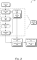
- Fig. 3 illustrates an example implementation 300 of hardware components of a force-sensing device configured for an ultra-low power mode.
- the example implementation represents a single integrated circuit (IC) channel.
- IC integrated circuit
- a plurality of IC channels may be implemented, each with an independent path.
- a subset of IC channels may share a single path.
- the sensor(s) 104 generates an analog signal that is sent to the analog front-end 106.
- the analog front-end 106 from Fig. 1 is illustrated as including a converter 302, a buffer 304, a filter 306, an optional absolute value block 308, and a comparator 310.
- the converter 302 can include any suitable converter, such as an analog-to-digital (AD) converter.
- the converter 302 converts the analog signal from the sensor(s) 104 into a digital signal and stores raw samples of the converted signal in the buffer 304, which allows the raw samples 312 to be available as historical data for subsequent analysis.
- the converter 302 sends the digital signal to the filter 306.
- the buffer 304 can be any suitable buffer.
- an example buffer 304 can be a first-in-first-out (FIFO) buffer or a ring buffer.
- the buffer can include any suitable depth, such as 250 milliseconds, 500 milliseconds, 750 milliseconds, 1.0 second, and so on. As described further below, the depth of the buffer depends on an amount of raw samples 312 (e.g., historical data) of the digital signal that are desired for gesture detection.
- the buffer includes one entry per AD converter sample and stores the samples in sequence. When multiple channels are used, the buffer 304 can be shared among all the channels or a subset of the channels.
- the filter 306 is configured to perform "baselining", which effectively removes a DC component from the digital signal.
- the filter 306 can take the first derivative of the digital signal to determine the rate of change (e.g., slope) of the signal.
- An instantaneous derivative can be obtained using the difference between the last two samples.
- the instantaneous derivative merely provides an estimate of the rate of change and is prone to trigger false alarms based on noise or drift.
- the derivative can be obtained using a high-pass filter, which allows derivatives above a certain value.
- the filter can be of any type and may be selected to minimize power and hardware.
- the filter can be implemented in hardware, such as silicon, with a set of fixed coefficients to form an autonomous high-pass filter. Consequently, the filter 306 can be implemented with low power.
- the filter 306 can be a high-pass filter with a predictable cutoff and phase delay.
- the filter 306 can be a band-pass filter that is configured for a band of interest, such as within a band of 5 Hz to 15 Hz.
- the filter 306 includes one or more coefficients to provide a high pass representation of the signal. Because the filter 306 determines the rate of change of the signal, the high pass representation of the signal is relative to a baseline rate of change. Thus, for a noisy, drifty sensor, the noise and drift in the signal are reduced or removed by the filter 306. For example, if the sensor 104 drifts up one value per second, then that value becomes the baseline rate of change, and portions of the signal changing at a slower rate are dismissible. Portions of the signal above the baseline rate of change leak through the filter and are passed on as filtered data. Accordingly, the filter 306 is configured to minimize false activation while maintaining adequate fidelity for gesture recognition. For example, the filter 306 is set higher than the drift but lower than a human gesture that is to be recognized.
- an absolute value block 308 is optionally used to remove negative values of the filter data. This saves the cost of additional digital logic that would be required to find negative value deviations from the baseline.
- the comparator 310 compares the filtered data to one or more registers (e.g., threshold values) to identify events that may be of interest. These events can exceed a maximum or minimum value, either of which may indicate a human gesture. Separate threshold values can be used to identify different types of human gestures, such as a squeeze-and-hold gesture, a quick squeeze-and-release gesture, a double squeeze-and-release gesture, and so on. In at least one implementation, these events can indicate "no activity" based on the filtered data settling to zero for a length of time. Events of interest may include deviations from the baseline above a known noise frequency caused by temperature drift or other sensor characteristics.
- a gesture may begin when the raw digital signal deviates by more than 1000 AD converter counts from the baseline.
- the comparator register can be set to around 1000 counts. If there are multiple registers or the sensor(s) 104 are reversed electronically or mechanically, then the system can also listen for negative 1000 counts. If the comparator has two registers, then the threshold values can be set at ⁇ -1000, 1000 ⁇ . If the absolute value block 308 is used, a single threshold value of 1000 counts can be used to identify deviations outside of the ⁇ -1000, 1000 ⁇ range. Due to the finite filter frequencies, this threshold may be adjusted.
- the microcontroller 110 comprises a low-power core that is responsible for management of the analog front-end 106.
- the microcontroller 110 can also respond to interrupts from the analog front-end 106.
- the microcontroller 110 is a digital signal processor (DSP) on a system-on-chip (SOC) designed for low-power operation, allowing the microcontroller 110 to handle infrequent events from the analog front-end 106 with near-zero power cost.
- DSP digital signal processor
- SOC system-on-chip
- the microcontroller 110 can execute the gesture module 116 to analyze the raw samples 312 (e.g., historical data) in the buffer 304 and determine whether the samples 312 correspond to a human gesture.
- Each sample 312 in the historical data may include information indicating a channel from which it was received and an indicator of whether that particular sample was associated with a comparator event that woke the microcontroller 110.
- the microcontroller 110 can roll back the historical data to discover an "interesting" part that triggered the wake up event of the microcontroller 110.
- continuity in the stream of data between sleep and wake states may be maintained. For instance, detection in the analog front-end 106 and consequent wakeup of the microcontroller 110 should be fast so as to not drop samples.
- the buffer 304 in the analog front-end 106 has a depth large enough to accommodate latency in waking the microcontroller 110. Some examples buffer depths include 45, 64, or 75 data items, but other buffer depths are also contemplated to accommodate the latency in waking the processor(s).
- the microcontroller 110 can return to the low-power idle state, thus preserving battery power. If a human gesture is recognized, however, then the microcontroller 110 wakes the application processor 112 from the low-power idle state.
- the application processor 112 can be any suitable high-power core that can execute a variety of different applications 122.
- the application processor 112 can execute the application 122 to handle the human gesture, such as by turning on a display device of the computing device 102.
- the application processor 112 can initiate another application, such as an image-capturing application, based on the human gesture.
- the application processor 112 responds to high-confidence gesture recognition (e.g., fully recognized gestures) from the microcontroller 110, and remains in the low-power idle state otherwise.
- the computing device 102 can utilize an ultra-low power mode in which both the microcontroller 110 and the application processor 112 are in the low-power idle state.
- the autonomously functioning analog front-end 106 filters the sensor signals based on a rate of change of the signals, and wakes the microcontroller 110 when the rate of change deviates from a baseline rate of change above a known noise frequency.
- the microcontroller 110 analyzes the sensor signals to recognize a gesture, and wakes the application processor 112 based on high-confidence gesture recognition. The application processor 112 can then handle the gesture.
- This ultra-low power mode may result in extended battery life of the computing device 102 due to both the microcontroller 110 and the high-power application processor 112 being woken from the low-power idle state less frequently in comparison to conventional techniques that constantly monitor DC thresholds and fail to account for drift in the sensors.
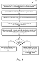
- Figure 4 illustrates example method 400 for managing an ultra-low power mode for a force-sensing device.
- an input signal is generated based on a detected force applied to a housing of a mobile device when the mobile device is in a low-power idle state.
- force sensors e.g., sensors 104 from Figure 1
- a converter e.g., converter 302 from Figure 3
- samples of the input signal are stored in a buffer.
- the converter 302 sends filtered samples to the buffer (e.g., buffer 304).
- the buffer is a FIFO buffer configured to hold about 1.0 second of samples.
- the input signal is filtered based on deviations from a baseline rate of change of the input signal.
- a filter e.g., filter 306 from Figure 3
- the baseline rate of change may correspond to a rate of change caused by drift in the sensors.
- an interrupt is triggered based on the deviations passing one or more threshold values.
- the one or more threshold values may correspond to a register of a comparator, such as comparator 310 from Figure 3 .
- the register may be set based on coefficients of hardware materials used to implement the analog front-end 106 of figure 2 .
- a microcontroller is woken from a low-power idle state based on the interrupt to analyze the samples in the buffer and determine whether the input signal corresponds to a human gesture.
- the microcontroller e.g., microcontroller 110 of Figure 1
- may execute a gesture module e.g., gesture module 116 of Figure 1 ) to read the raw samples stored in the buffer.
- the gesture module 116 may determine that the raw samples stored in the buffer correspond to a human gesture based on an amount of force applied to the housing and a time associated with the applied force.
- the microcontroller is returned to the low-power idle state. For example, if the data in the buffer does not match or correspond to a human gesture (e.g., the force is too weak, or is held for too short or long), then there is no need to wake a high-power application processor and the microcontroller can return to the low-power idle state.
- a human gesture e.g., the force is too weak, or is held for too short or long
- an application processor is woken from a low-power idle state based on recognition of the human gesture to execute an application configured to perform an operation mapped to the human gesture.
- an interrupt is generated to wake the high-power application processor to allow the application processor process the gesture, such as by powering on a display device and/or initiating an application.
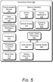
- Fig. 5 illustrates various components of example computing system 500 that can be implemented as any type of client, server, and/or computing device as described with reference to the previous Figs. 1-4 to enable an ultra-low power mode for a force-sensing device.
- the computing system 500 can be implemented as one or a combination of a wired and/or wireless wearable device, System-on-Chip (SoC), and/or as another type of device or portion thereof.
- SoC System-on-Chip
- the computing system 500 may also be associated with a user (e.g., a person wishing to wake the computing system from the ultra-low power mode) and/or an entity that operates a device such that the device describes logical devices that include software, firmware, and/or a combination of devices.
- a user e.g., a person wishing to wake the computing system from the ultra-low power mode
- an entity that operates a device such that the device describes logical devices that include software, firmware, and/or a combination of devices.
- the computing system 500 includes the analog front-end 106 of Figs. 1-3 , though this component need not be exactly as illustrated.
- the analog front-end 106 can be integral with the computing system 500 through integration with a mother board, or separate from, but within the computing systems 500 frame, chassis, or other structure.
- the computing system 500 includes communication devices 502 that enable wired and/or wireless communication of device data 504 (e.g., received data, data that is being received, data scheduled for broadcast, data packets of the data, etc.).
- the device data 504 or other device content can include configuration settings of the device, media content stored on the device, and/or information associated with a user of the device.
- Media content stored on the computing system 500 can include any type of audio, video, and/or image data, and can be a resource or information to which access is desired.
- the computing system 500 includes one or more data input ports 506 via which any type of data, media content, and/or inputs can be received, such as human utterances, user-selectable inputs (explicit or implicit), physical, selectable structures, messages, music, television media content, recorded video content, and any other type of audio, video, and/or image data received from any content and/or data source.
- any type of data, media content, and/or inputs can be received, such as human utterances, user-selectable inputs (explicit or implicit), physical, selectable structures, messages, music, television media content, recorded video content, and any other type of audio, video, and/or image data received from any content and/or data source.
- the computing system 500 also includes communication interfaces 508, which can be implemented as any one or more of a serial and/or parallel interface, a wireless interface, any type of network interface, a modem, and as any other type of communication interface, such as near field communication (NFC) wireless interfaces.
- the communication interfaces 508 provide a connection and/or communication links between the computing system 500 and a communication network by which other electronic, computing, and communication devices communicate data with the computing system 500.
- the computing system 500 includes one or more processors 510 (e.g., any of microcontrollers, application processors, digital-signal-processors, controllers, and the like), or a processor and memory system (e.g., implemented in a SoC), which process (e.g., execute) various computer-executable instructions to control operation of the computing system 500 and to enable techniques for, or in which can be embodied, an ultra-low power mode for a force-sensing device.
- processors 510 e.g., any of microcontrollers, application processors, digital-signal-processors, controllers, and the like
- a processor and memory system e.g., implemented in a SoC
- process e.g., execute
- various computer-executable instructions to control operation of the computing system 500 and to enable techniques for, or in which can be embodied, an ultra-low power mode for a force-sensing device.
- the computing system 500 can be implemented with any one or combination of
- the computing system 500 can include a system bus or data transfer system that couples the various components within the device.
- a system bus can include any one or combination of different bus structures, such as a memory bus or memory controller, a peripheral bus, a universal serial bus, and/or a processor or local bus that utilizes any of a variety of bus architectures.
- the computing system 500 also includes one or more memory devices 514 that enable persistent and/or non-transitory data storage (i.e., in contrast to mere signal transmission), examples of which include random access memory (RAM), non-volatile memory (e.g., any one or more of a read-only memory (ROM), flash memory, EPROM, EEPROM, etc.), and a disk storage device.
- RAM random access memory
- non-volatile memory e.g., any one or more of a read-only memory (ROM), flash memory, EPROM, EEPROM, etc.
- a disk storage device may be implemented as any type of magnetic or optical storage device, such as a hard disk drive, a recordable and/or rewriteable compact disc (CD), any type of a digital versatile disc (DVD), and the like.
- Memory device(s) 514 provide data storage mechanisms to store the device data 504, other types of information and/or data, and various device applications 516 (e.g., software applications).
- operating system 518 can be maintained as software instructions within memory device 514 and executed by processors 510.
- the gesture module 116 is embodied in memory devices 514 of the computing system 500 as executable instructions or code. Although represented as a software implementation, the gesture module 116 may be implemented as any form of a control application, software application, signal-processing and control module, or hardware or firmware installed on the computing system 500.
- the computing system 500 also includes audio and/or video processing system 520 that processes audio data and/or passes through the audio and video data to audio system 522 and/or to display system 524 (e.g., a screen of a smartphone or camera).
- Audio system 522 and/or display system 524 may include any devices that process, display, and/or otherwise render audio, video, display, and/or image data.
- Display data and audio signals can be communicated to an audio component and/or to a display component via an RF (radio frequency) link, S-video link, HDMI (high-definition multimedia interface), composite video link, component video link, DVI (digital video interface), analog audio connection, or other similar communication link, such as media data port 526.
- audio system 522 and/or display system 524 are external components to computing system 500.
- display system 524 can be an integrated component of the computing system 500, such as part of an integrated touch interface.
Landscapes
- Engineering & Computer Science (AREA)
- Theoretical Computer Science (AREA)
- General Engineering & Computer Science (AREA)
- Physics & Mathematics (AREA)
- General Physics & Mathematics (AREA)
- Automation & Control Theory (AREA)
- Human Computer Interaction (AREA)
- User Interface Of Digital Computer (AREA)
- Power Sources (AREA)
Claims (14)
- System, Folgendes umfassend:eine Mehrzahl von Prozessoren (202), umfassend mindestens einen Mikrocontroller (110) und einen Hochleistungs-Anwendungsprozessor (112), welche jeweils konfiguriert sind, um in einen suspendierten Zustand versetzt zu werden; undein analoges Frontend (106), welches in Hardware implementiert ist und konfiguriert ist, zum:Wandeln eines analogen Signals, welches durch einen Kraftsensor (104) erzeugt wird, in ein digitales Signal;Speichern von Abtastwerten des digitalen Signals in einen Puffer;Filtern des digitalen Signals, um Abweichungen in einer Änderungsrate des Signals von einem Basislinienwert zu bestimmen
undals Reaktion auf das Überschreiten durch das gefilterte digitale Signal von einem oder mehreren Schwellenwerten, Wecken des Mikrocontrollers (110) von dem suspendierten Zustand, um die Abtastwerte des digitalen Signals in dem Puffer zu analysieren, um zu bestimmen, ob das digitale Signal einer menschlichen Geste entspricht, wobei der Mikrocontroller (110) konfiguriert ist, um den Hochleistungs-Anwendungsprozessor (112) von dem suspendierten Zustand zu wecken, um die menschliche Geste zu verarbeiten, basierend auf der Tatsache, dass das digitale Signal als eine menschliche Geste erkannt wurde. - System nach Anspruch 1, wobei das analoge Frontend (106) konfiguriert ist, um autonom zu funktionieren.
- System nach Anspruch 1 oder Anspruch 2, wobei der Puffer einen First-In-First-Out-(FIFO)-Puffer umfasst, der konfiguriert ist, um bis etwa eine Sekunde der Abtastwerte zu speichern.
- System nach einem der vorhergehenden Ansprüche, wobei der Filter (306) einen Hochpassfilter oder einen Bandpassfilter umfasst.
- System nach einem der vorhergehenden Ansprüche, wobei der Mikrocontroller (110) konfiguriert ist, um in den suspendierten Zustand zurückzukehren, als Reaktion auf die gescheiterte Erkennung des Signals als menschliche Geste.
- System nach einem der vorhergehenden Ansprüche, wobei das System eine Mehrzahl von integrierten Schaltungskanälen umfasst, welche jeweils einem separaten Filter zugeordnet sind.
- System nach Anspruch 6, wobei der Puffer von einer Teilmenge der Mehrzahl von integrierten Schaltungskanälen gemeinsam genutzt wird.
- System nach einem der vorhergehenden Ansprüche, wobei das System ferner den Kraftsensor (104) umfasst und wobei der Kraftsensor (104) einen Dehnungsmesser umfasst, welcher konfiguriert ist, um eine Kraft zu messen, welche auf ein Gehäuse (114) ausgeübt wird, und die menschliche Geste eine Quetschgeste umfasst, die die Kraft auf gegenüberliegende Seiten des Gehäuses ausübt.
- Verfahren zum Verwalten eines Ultraniedrigleistungsmodus für eine mobile Vorrichtung, wobei das Verfahren Folgendes umfasst:Erzeugen eines Eingangssignals basierend auf der Detektion einer Kraft, die auf ein Gehäuse (114) der mobilen Vorrichtung ausgeübt wird, wenn die mobile Vorrichtung sich in einem Ultraniedrigleistungsmodus befindet;Speichern von Abtastwerten des Eingangssignals in einem Puffer;Filtern des digitalen Signals, um Abweichungen in einer Änderungsrate des Signals im Verhältnis zu einem Basislinienwert zu bestimmen;Auslösen eines Interrupts, basierend auf dem Überschreiten, durch die Abweichungen, eines oder mehrerer Schwellenwerte; undWecken eines Mikrocontrollers (110) von einem Niedrigleistung-Ruhezustand, basierend auf dem Interrupt, um die Abtastwerte in dem Puffer zu analysieren und zu bestimmen, ob das Eingangssignal einer menschlichen Geste entspricht
undWecken eines Anwendungsprozessors (112) von einem Niedrigleistung-Ruhezustand, basierend auf der Erkennung der menschlichen Geste, um eine Anwendung auszuführen, welche konfiguriert ist, um eine Operation auszuführen, welche der menschlichen Geste zugeordnet ist. - Verfahren nach Anspruch 9, wobei das Detektieren einer Kraft, welche auf ein Gehäuse (114) ausgeübt wird, das Detektieren einer Kompressionskraft umfasst, welche auf gegenüberliegenden Seiten des Gehäuses (114) ausgeübt wird.
- Verfahren nach einem der Ansprüche 9 bis 10, ferner umfassend:Zurückweisen des Eingangssignals als menschliche Geste, basierend auf den Abtastwerten in dem Puffer; undZurückkehren des Mikrocontrollers (110) in den Niedrigleistung-Ruhezustand.
- Verfahren nach einem der Ansprüche 9 bis 11,
wobei das Eingangssignal durch einen oder mehrere Kraftsensoren (104) erzeugt wird. - Verfahren nach einem der Ansprüche 9 bis 12,
wobei das Filtern des Eingangssignals das Verwenden eines Hochpassfilters oder eines Bandpassfilters umfasst. - Verfahren nach einem der Ansprüche 9 bis 13,
wobei das Auslösen eines Interrupts das Auslösen des Interrupts umfasst, basierend auf der Tatsache, dass ein absoluter Wert der Abweichungen größer als mindestens einer des einen oder der mehreren Schwellenwerte ist.
Priority Applications (1)
| Application Number | Priority Date | Filing Date | Title |
|---|---|---|---|
| EP21158920.5A EP3851938A1 (de) | 2017-12-15 | 2018-11-29 | Ultraniedrigleistungsmodus für eine kostengünstige kraftmessvorrichtung |
Applications Claiming Priority (2)
| Application Number | Priority Date | Filing Date | Title |
|---|---|---|---|
| US15/844,153 US10613619B2 (en) | 2017-12-15 | 2017-12-15 | Ultra-low power mode for a low-cost force-sensing device |
| PCT/US2018/062957 WO2019118183A1 (en) | 2017-12-15 | 2018-11-29 | Ultra-low power mode for a low-cost force-sensing device |
Related Child Applications (2)
| Application Number | Title | Priority Date | Filing Date |
|---|---|---|---|
| EP21158920.5A Division EP3851938A1 (de) | 2017-12-15 | 2018-11-29 | Ultraniedrigleistungsmodus für eine kostengünstige kraftmessvorrichtung |
| EP21158920.5A Division-Into EP3851938A1 (de) | 2017-12-15 | 2018-11-29 | Ultraniedrigleistungsmodus für eine kostengünstige kraftmessvorrichtung |
Publications (2)
| Publication Number | Publication Date |
|---|---|
| EP3602240A1 EP3602240A1 (de) | 2020-02-05 |
| EP3602240B1 true EP3602240B1 (de) | 2021-07-07 |
Family
ID=64665130
Family Applications (2)
| Application Number | Title | Priority Date | Filing Date |
|---|---|---|---|
| EP18819298.3A Active EP3602240B1 (de) | 2017-12-15 | 2018-11-29 | Ultraniedrigleistungsmodus für eine kostengünstige kraftmessvorrichtung |
| EP21158920.5A Withdrawn EP3851938A1 (de) | 2017-12-15 | 2018-11-29 | Ultraniedrigleistungsmodus für eine kostengünstige kraftmessvorrichtung |
Family Applications After (1)
| Application Number | Title | Priority Date | Filing Date |
|---|---|---|---|
| EP21158920.5A Withdrawn EP3851938A1 (de) | 2017-12-15 | 2018-11-29 | Ultraniedrigleistungsmodus für eine kostengünstige kraftmessvorrichtung |
Country Status (7)
| Country | Link |
|---|---|
| US (1) | US10613619B2 (de) |
| EP (2) | EP3602240B1 (de) |
| JP (1) | JP6952130B2 (de) |
| KR (1) | KR102253100B1 (de) |
| CN (1) | CN110573990B (de) |
| TW (1) | TWI698739B (de) |
| WO (1) | WO2019118183A1 (de) |
Families Citing this family (8)
| Publication number | Priority date | Publication date | Assignee | Title |
|---|---|---|---|---|
| KR20170050702A (ko) * | 2015-10-30 | 2017-05-11 | 삼성전자주식회사 | 제스처 감지 방법 및 이를 지원하는 전자 장치 |
| US20210304077A1 (en) * | 2018-11-13 | 2021-09-30 | Sony Corporation | Method and system for damage classification |
| US11720158B2 (en) * | 2020-03-13 | 2023-08-08 | Google Llc | Power throttling mechanism using instruction rate limiting in high power machine-learning ASICs |
| WO2021257072A1 (en) * | 2020-06-17 | 2021-12-23 | Google Llc | Multi-radar system |
| CN115236135B (zh) * | 2021-04-23 | 2023-08-22 | 中国石油化工股份有限公司 | 用于气体传感器的基线校准方法、控制装置和气体传感器 |
| US11822413B1 (en) * | 2021-05-11 | 2023-11-21 | Biofire Technologies Inc. | Systems and techniques for improving battery life in an electromechanical gun |
| US11797099B1 (en) * | 2022-09-19 | 2023-10-24 | Snap Inc. | Visual and audio wake commands |
| US12405915B2 (en) | 2023-09-08 | 2025-09-02 | Qualcomm Incorporated | Waveform-aware mixed signal measurement system for bus traffic reduction in system-on-a-chip devices |
Family Cites Families (18)
| Publication number | Priority date | Publication date | Assignee | Title |
|---|---|---|---|---|
| US20090140985A1 (en) | 2007-11-30 | 2009-06-04 | Eric Liu | Computing device that determines and uses applied pressure from user interaction with an input interface |
| US8996332B2 (en) | 2008-06-24 | 2015-03-31 | Dp Technologies, Inc. | Program setting adjustments based on activity identification |
| KR101540453B1 (ko) * | 2009-05-25 | 2015-07-30 | (주)멜파스 | 압력 기반의 입력 장치 및 입력 감지 방법 |
| US8970507B2 (en) * | 2009-10-02 | 2015-03-03 | Blackberry Limited | Method of waking up and a portable electronic device configured to perform the same |
| US8432368B2 (en) * | 2010-01-06 | 2013-04-30 | Qualcomm Incorporated | User interface methods and systems for providing force-sensitive input |
| US8775838B2 (en) * | 2012-02-01 | 2014-07-08 | Texas Instruments Incorporated | Limiting the number of unexpected wakeups in a computer system implementing a power-saving preemptive wakeup method from historical data |
| WO2014017777A1 (en) * | 2012-07-26 | 2014-01-30 | Lg Electronics Inc. | Mobile terminal and control method thereof |
| US9063731B2 (en) * | 2012-08-27 | 2015-06-23 | Samsung Electronics Co., Ltd. | Ultra low power apparatus and method to wake up a main processor |
| US9081571B2 (en) | 2012-11-29 | 2015-07-14 | Amazon Technologies, Inc. | Gesture detection management for an electronic device |
| US9146605B2 (en) | 2013-01-31 | 2015-09-29 | Salutron, Inc. | Ultra low power actigraphy based on dynamic threshold |
| US9086749B2 (en) * | 2013-08-30 | 2015-07-21 | Qualcomm Incorporated | System and method for improved processing of touch sensor data |
| US9513703B2 (en) * | 2013-12-27 | 2016-12-06 | Intel Corporation | Gesture-based waking and control system for wearable devices |
| US10302499B2 (en) | 2014-10-24 | 2019-05-28 | Google Llc | Adaptive threshold manipulation for movement detecting sensors |
| US9959128B2 (en) * | 2014-11-06 | 2018-05-01 | Infineon Technologies Ag | Digital sensor system |
| CN104280157A (zh) | 2014-11-07 | 2015-01-14 | 上海艾络格电子技术有限公司 | 一种低功耗变送器 |
| JP2016136351A (ja) * | 2015-01-23 | 2016-07-28 | 京セラ株式会社 | 電子機器及び制御方法 |
| US10835333B2 (en) | 2015-08-25 | 2020-11-17 | Kawasaki Jukogyo Kabushiki Kaisha | Remote control robot system |
| KR102628789B1 (ko) * | 2016-09-09 | 2024-01-25 | 삼성전자주식회사 | 전자 장치 및 전자 장치의 제어 방법 |
-
2017
- 2017-12-15 US US15/844,153 patent/US10613619B2/en active Active
-
2018
- 2018-11-19 TW TW107141064A patent/TWI698739B/zh active
- 2018-11-29 WO PCT/US2018/062957 patent/WO2019118183A1/en not_active Ceased
- 2018-11-29 JP JP2019559792A patent/JP6952130B2/ja active Active
- 2018-11-29 EP EP18819298.3A patent/EP3602240B1/de active Active
- 2018-11-29 EP EP21158920.5A patent/EP3851938A1/de not_active Withdrawn
- 2018-11-29 CN CN201880028911.1A patent/CN110573990B/zh active Active
- 2018-11-29 KR KR1020197031168A patent/KR102253100B1/ko active Active
Non-Patent Citations (1)
| Title |
|---|
| None * |
Also Published As
| Publication number | Publication date |
|---|---|
| US10613619B2 (en) | 2020-04-07 |
| WO2019118183A1 (en) | 2019-06-20 |
| EP3851938A1 (de) | 2021-07-21 |
| CN110573990B (zh) | 2023-07-25 |
| CN110573990A (zh) | 2019-12-13 |
| TWI698739B (zh) | 2020-07-11 |
| KR20190131087A (ko) | 2019-11-25 |
| KR102253100B1 (ko) | 2021-05-14 |
| US20190187776A1 (en) | 2019-06-20 |
| JP2020525879A (ja) | 2020-08-27 |
| JP6952130B2 (ja) | 2021-10-20 |
| EP3602240A1 (de) | 2020-02-05 |
| TW201928593A (zh) | 2019-07-16 |
Similar Documents
| Publication | Publication Date | Title |
|---|---|---|
| EP3602240B1 (de) | Ultraniedrigleistungsmodus für eine kostengünstige kraftmessvorrichtung | |
| US9690361B2 (en) | Low-power context-aware control for analog frontend | |
| US9654846B2 (en) | Sensor based signal transmission methods and apparatuses | |
| US10653369B2 (en) | Device for health monitoring and response | |
| CN104850214B (zh) | 一种通过预测用户唤醒意图缩短移动终端唤醒时间的方法 | |
| US10082598B2 (en) | Sensor power management | |
| CN110096135A (zh) | 具有传感器集线器的移动设备以及控制该设备的方法 | |
| EP3230854A1 (de) | Fitnesssensor mit niedrigleistungseigenschaften in einem sensorhub | |
| US11809348B2 (en) | Digital bus activity monitor | |
| CN104007882A (zh) | 一种准确性高的触屏响应方法和装置 | |
| CN106913313B (zh) | 一种睡眠监测方法及系统 | |
| WO2018098719A1 (zh) | 一种睡眠监测方法、装置及终端 | |
| WO2015169242A1 (zh) | 一种能够自动调度测量设备电源的方法及设备 | |
| CN116369861B (zh) | 一种在床离床状态的确定方法、装置、智能床垫及介质 | |
| CN109828882A (zh) | Cpu温度和系统环境温度监控装置 | |
| CN115793834A (zh) | 电子设备及将电子设备从休眠模式唤醒的方法 | |
| CN115616954A (zh) | 电动牙刷的唤醒方法及装置、电子设备和存储介质 | |
| US11134194B2 (en) | Always-on system with multi-layer power management | |
| CN116530793B (zh) | 一种基于智能床垫的数据处理方法、装置、设备及介质 | |
| CN113448414B (zh) | 具有多层功率管理的常开系统 | |
| EP4581451A1 (de) | Passive näherungsdetektion unter verwendung einer elektrode | |
| Lee et al. | Event-driven read-out circuits for energy-efficient sensor-SoC's |
Legal Events
| Date | Code | Title | Description |
|---|---|---|---|
| STAA | Information on the status of an ep patent application or granted ep patent |
Free format text: STATUS: UNKNOWN |
|
| STAA | Information on the status of an ep patent application or granted ep patent |
Free format text: STATUS: THE INTERNATIONAL PUBLICATION HAS BEEN MADE |
|
| PUAI | Public reference made under article 153(3) epc to a published international application that has entered the european phase |
Free format text: ORIGINAL CODE: 0009012 |
|
| STAA | Information on the status of an ep patent application or granted ep patent |
Free format text: STATUS: REQUEST FOR EXAMINATION WAS MADE |
|
| 17P | Request for examination filed |
Effective date: 20191023 |
|
| AK | Designated contracting states |
Kind code of ref document: A1 Designated state(s): AL AT BE BG CH CY CZ DE DK EE ES FI FR GB GR HR HU IE IS IT LI LT LU LV MC MK MT NL NO PL PT RO RS SE SI SK SM TR |
|
| AX | Request for extension of the european patent |
Extension state: BA ME |
|
| RAP1 | Party data changed (applicant data changed or rights of an application transferred) |
Owner name: GOOGLE LLC |
|
| GRAP | Despatch of communication of intention to grant a patent |
Free format text: ORIGINAL CODE: EPIDOSNIGR1 |
|
| STAA | Information on the status of an ep patent application or granted ep patent |
Free format text: STATUS: GRANT OF PATENT IS INTENDED |
|
| DAV | Request for validation of the european patent (deleted) | ||
| DAX | Request for extension of the european patent (deleted) | ||
| INTG | Intention to grant announced |
Effective date: 20201016 |
|
| GRAS | Grant fee paid |
Free format text: ORIGINAL CODE: EPIDOSNIGR3 |
|
| GRAJ | Information related to disapproval of communication of intention to grant by the applicant or resumption of examination proceedings by the epo deleted |
Free format text: ORIGINAL CODE: EPIDOSDIGR1 |
|
| GRAL | Information related to payment of fee for publishing/printing deleted |
Free format text: ORIGINAL CODE: EPIDOSDIGR3 |
|
| STAA | Information on the status of an ep patent application or granted ep patent |
Free format text: STATUS: REQUEST FOR EXAMINATION WAS MADE |
|
| GRAP | Despatch of communication of intention to grant a patent |
Free format text: ORIGINAL CODE: EPIDOSNIGR1 |
|
| STAA | Information on the status of an ep patent application or granted ep patent |
Free format text: STATUS: GRANT OF PATENT IS INTENDED |
|
| INTC | Intention to grant announced (deleted) | ||
| INTG | Intention to grant announced |
Effective date: 20210325 |
|
| GRAA | (expected) grant |
Free format text: ORIGINAL CODE: 0009210 |
|
| STAA | Information on the status of an ep patent application or granted ep patent |
Free format text: STATUS: THE PATENT HAS BEEN GRANTED |
|
| AK | Designated contracting states |
Kind code of ref document: B1 Designated state(s): AL AT BE BG CH CY CZ DE DK EE ES FI FR GB GR HR HU IE IS IT LI LT LU LV MC MK MT NL NO PL PT RO RS SE SI SK SM TR |
|
| REG | Reference to a national code |
Ref country code: GB Ref legal event code: FG4D |
|
| REG | Reference to a national code |
Ref country code: AT Ref legal event code: REF Ref document number: 1409207 Country of ref document: AT Kind code of ref document: T Effective date: 20210715 |
|
| REG | Reference to a national code |
Ref country code: DE Ref legal event code: R096 Ref document number: 602018019888 Country of ref document: DE |
|
| REG | Reference to a national code |
Ref country code: IE Ref legal event code: FG4D |
|
| REG | Reference to a national code |
Ref country code: NL Ref legal event code: FP |
|
| REG | Reference to a national code |
Ref country code: LT Ref legal event code: MG9D |
|
| REG | Reference to a national code |
Ref country code: AT Ref legal event code: MK05 Ref document number: 1409207 Country of ref document: AT Kind code of ref document: T Effective date: 20210707 |
|
| PG25 | Lapsed in a contracting state [announced via postgrant information from national office to epo] |
Ref country code: RS Free format text: LAPSE BECAUSE OF FAILURE TO SUBMIT A TRANSLATION OF THE DESCRIPTION OR TO PAY THE FEE WITHIN THE PRESCRIBED TIME-LIMIT Effective date: 20210707 Ref country code: SE Free format text: LAPSE BECAUSE OF FAILURE TO SUBMIT A TRANSLATION OF THE DESCRIPTION OR TO PAY THE FEE WITHIN THE PRESCRIBED TIME-LIMIT Effective date: 20210707 Ref country code: FI Free format text: LAPSE BECAUSE OF FAILURE TO SUBMIT A TRANSLATION OF THE DESCRIPTION OR TO PAY THE FEE WITHIN THE PRESCRIBED TIME-LIMIT Effective date: 20210707 Ref country code: ES Free format text: LAPSE BECAUSE OF FAILURE TO SUBMIT A TRANSLATION OF THE DESCRIPTION OR TO PAY THE FEE WITHIN THE PRESCRIBED TIME-LIMIT Effective date: 20210707 Ref country code: NO Free format text: LAPSE BECAUSE OF FAILURE TO SUBMIT A TRANSLATION OF THE DESCRIPTION OR TO PAY THE FEE WITHIN THE PRESCRIBED TIME-LIMIT Effective date: 20211007 Ref country code: PT Free format text: LAPSE BECAUSE OF FAILURE TO SUBMIT A TRANSLATION OF THE DESCRIPTION OR TO PAY THE FEE WITHIN THE PRESCRIBED TIME-LIMIT Effective date: 20211108 Ref country code: HR Free format text: LAPSE BECAUSE OF FAILURE TO SUBMIT A TRANSLATION OF THE DESCRIPTION OR TO PAY THE FEE WITHIN THE PRESCRIBED TIME-LIMIT Effective date: 20210707 Ref country code: BG Free format text: LAPSE BECAUSE OF FAILURE TO SUBMIT A TRANSLATION OF THE DESCRIPTION OR TO PAY THE FEE WITHIN THE PRESCRIBED TIME-LIMIT Effective date: 20211007 Ref country code: AT Free format text: LAPSE BECAUSE OF FAILURE TO SUBMIT A TRANSLATION OF THE DESCRIPTION OR TO PAY THE FEE WITHIN THE PRESCRIBED TIME-LIMIT Effective date: 20210707 Ref country code: LT Free format text: LAPSE BECAUSE OF FAILURE TO SUBMIT A TRANSLATION OF THE DESCRIPTION OR TO PAY THE FEE WITHIN THE PRESCRIBED TIME-LIMIT Effective date: 20210707 |
|
| PG25 | Lapsed in a contracting state [announced via postgrant information from national office to epo] |
Ref country code: PL Free format text: LAPSE BECAUSE OF FAILURE TO SUBMIT A TRANSLATION OF THE DESCRIPTION OR TO PAY THE FEE WITHIN THE PRESCRIBED TIME-LIMIT Effective date: 20210707 Ref country code: LV Free format text: LAPSE BECAUSE OF FAILURE TO SUBMIT A TRANSLATION OF THE DESCRIPTION OR TO PAY THE FEE WITHIN THE PRESCRIBED TIME-LIMIT Effective date: 20210707 Ref country code: GR Free format text: LAPSE BECAUSE OF FAILURE TO SUBMIT A TRANSLATION OF THE DESCRIPTION OR TO PAY THE FEE WITHIN THE PRESCRIBED TIME-LIMIT Effective date: 20211008 |
|
| REG | Reference to a national code |
Ref country code: DE Ref legal event code: R097 Ref document number: 602018019888 Country of ref document: DE |
|
| PG25 | Lapsed in a contracting state [announced via postgrant information from national office to epo] |
Ref country code: DK Free format text: LAPSE BECAUSE OF FAILURE TO SUBMIT A TRANSLATION OF THE DESCRIPTION OR TO PAY THE FEE WITHIN THE PRESCRIBED TIME-LIMIT Effective date: 20210707 |
|
| PLBE | No opposition filed within time limit |
Free format text: ORIGINAL CODE: 0009261 |
|
| STAA | Information on the status of an ep patent application or granted ep patent |
Free format text: STATUS: NO OPPOSITION FILED WITHIN TIME LIMIT |
|
| PG25 | Lapsed in a contracting state [announced via postgrant information from national office to epo] |
Ref country code: SM Free format text: LAPSE BECAUSE OF FAILURE TO SUBMIT A TRANSLATION OF THE DESCRIPTION OR TO PAY THE FEE WITHIN THE PRESCRIBED TIME-LIMIT Effective date: 20210707 Ref country code: SK Free format text: LAPSE BECAUSE OF FAILURE TO SUBMIT A TRANSLATION OF THE DESCRIPTION OR TO PAY THE FEE WITHIN THE PRESCRIBED TIME-LIMIT Effective date: 20210707 Ref country code: RO Free format text: LAPSE BECAUSE OF FAILURE TO SUBMIT A TRANSLATION OF THE DESCRIPTION OR TO PAY THE FEE WITHIN THE PRESCRIBED TIME-LIMIT Effective date: 20210707 Ref country code: EE Free format text: LAPSE BECAUSE OF FAILURE TO SUBMIT A TRANSLATION OF THE DESCRIPTION OR TO PAY THE FEE WITHIN THE PRESCRIBED TIME-LIMIT Effective date: 20210707 Ref country code: CZ Free format text: LAPSE BECAUSE OF FAILURE TO SUBMIT A TRANSLATION OF THE DESCRIPTION OR TO PAY THE FEE WITHIN THE PRESCRIBED TIME-LIMIT Effective date: 20210707 Ref country code: AL Free format text: LAPSE BECAUSE OF FAILURE TO SUBMIT A TRANSLATION OF THE DESCRIPTION OR TO PAY THE FEE WITHIN THE PRESCRIBED TIME-LIMIT Effective date: 20210707 |
|
| 26N | No opposition filed |
Effective date: 20220408 |
|
| PG25 | Lapsed in a contracting state [announced via postgrant information from national office to epo] |
Ref country code: MC Free format text: LAPSE BECAUSE OF FAILURE TO SUBMIT A TRANSLATION OF THE DESCRIPTION OR TO PAY THE FEE WITHIN THE PRESCRIBED TIME-LIMIT Effective date: 20210707 |
|
| REG | Reference to a national code |
Ref country code: CH Ref legal event code: PL |
|
| PG25 | Lapsed in a contracting state [announced via postgrant information from national office to epo] |
Ref country code: LU Free format text: LAPSE BECAUSE OF NON-PAYMENT OF DUE FEES Effective date: 20211129 Ref country code: IT Free format text: LAPSE BECAUSE OF FAILURE TO SUBMIT A TRANSLATION OF THE DESCRIPTION OR TO PAY THE FEE WITHIN THE PRESCRIBED TIME-LIMIT Effective date: 20210707 Ref country code: BE Free format text: LAPSE BECAUSE OF NON-PAYMENT OF DUE FEES Effective date: 20211130 |
|
| REG | Reference to a national code |
Ref country code: BE Ref legal event code: MM Effective date: 20211130 |
|
| PG25 | Lapsed in a contracting state [announced via postgrant information from national office to epo] |
Ref country code: LI Free format text: LAPSE BECAUSE OF NON-PAYMENT OF DUE FEES Effective date: 20211130 Ref country code: CH Free format text: LAPSE BECAUSE OF NON-PAYMENT OF DUE FEES Effective date: 20211130 |
|
| PG25 | Lapsed in a contracting state [announced via postgrant information from national office to epo] |
Ref country code: IE Free format text: LAPSE BECAUSE OF NON-PAYMENT OF DUE FEES Effective date: 20211129 |
|
| P01 | Opt-out of the competence of the unified patent court (upc) registered |
Effective date: 20230505 |
|
| PG25 | Lapsed in a contracting state [announced via postgrant information from national office to epo] |
Ref country code: CY Free format text: LAPSE BECAUSE OF FAILURE TO SUBMIT A TRANSLATION OF THE DESCRIPTION OR TO PAY THE FEE WITHIN THE PRESCRIBED TIME-LIMIT Effective date: 20210707 |
|
| PG25 | Lapsed in a contracting state [announced via postgrant information from national office to epo] |
Ref country code: HU Free format text: LAPSE BECAUSE OF FAILURE TO SUBMIT A TRANSLATION OF THE DESCRIPTION OR TO PAY THE FEE WITHIN THE PRESCRIBED TIME-LIMIT; INVALID AB INITIO Effective date: 20181129 |
|
| PG25 | Lapsed in a contracting state [announced via postgrant information from national office to epo] |
Ref country code: MK Free format text: LAPSE BECAUSE OF FAILURE TO SUBMIT A TRANSLATION OF THE DESCRIPTION OR TO PAY THE FEE WITHIN THE PRESCRIBED TIME-LIMIT Effective date: 20210707 |
|
| PG25 | Lapsed in a contracting state [announced via postgrant information from national office to epo] |
Ref country code: MT Free format text: LAPSE BECAUSE OF FAILURE TO SUBMIT A TRANSLATION OF THE DESCRIPTION OR TO PAY THE FEE WITHIN THE PRESCRIBED TIME-LIMIT Effective date: 20210707 |
|
| PG25 | Lapsed in a contracting state [announced via postgrant information from national office to epo] |
Ref country code: TR Free format text: LAPSE BECAUSE OF FAILURE TO SUBMIT A TRANSLATION OF THE DESCRIPTION OR TO PAY THE FEE WITHIN THE PRESCRIBED TIME-LIMIT Effective date: 20210707 |
|
| PGFP | Annual fee paid to national office [announced via postgrant information from national office to epo] |
Ref country code: NL Payment date: 20251126 Year of fee payment: 8 |
|
| PGFP | Annual fee paid to national office [announced via postgrant information from national office to epo] |
Ref country code: DE Payment date: 20251128 Year of fee payment: 8 |
|
| PGFP | Annual fee paid to national office [announced via postgrant information from national office to epo] |
Ref country code: GB Payment date: 20251127 Year of fee payment: 8 |
|
| PGFP | Annual fee paid to national office [announced via postgrant information from national office to epo] |
Ref country code: FR Payment date: 20251125 Year of fee payment: 8 |