EP3602229B1 - Procédé et dispositif d'optimisation, basée sur internet, de paramètres d'une régulation de chauffage - Google Patents
Procédé et dispositif d'optimisation, basée sur internet, de paramètres d'une régulation de chauffage Download PDFInfo
- Publication number
- EP3602229B1 EP3602229B1 EP18703577.9A EP18703577A EP3602229B1 EP 3602229 B1 EP3602229 B1 EP 3602229B1 EP 18703577 A EP18703577 A EP 18703577A EP 3602229 B1 EP3602229 B1 EP 3602229B1
- Authority
- EP
- European Patent Office
- Prior art keywords
- control parameters
- optimized control
- server
- data packet
- data packets
- Prior art date
- Legal status (The legal status is an assumption and is not a legal conclusion. Google has not performed a legal analysis and makes no representation as to the accuracy of the status listed.)
- Active
Links
- 238000010438 heat treatment Methods 0.000 title claims description 123
- 238000000034 method Methods 0.000 title claims description 62
- 238000005457 optimization Methods 0.000 title description 11
- 238000005259 measurement Methods 0.000 claims description 19
- 238000004422 calculation algorithm Methods 0.000 claims description 15
- 238000004378 air conditioning Methods 0.000 claims description 6
- 238000005057 refrigeration Methods 0.000 claims description 6
- 238000009423 ventilation Methods 0.000 claims description 6
- 230000005540 biological transmission Effects 0.000 claims description 4
- 238000001514 detection method Methods 0.000 claims 2
- 230000001419 dependent effect Effects 0.000 claims 1
- 238000004364 calculation method Methods 0.000 description 17
- 230000005855 radiation Effects 0.000 description 15
- 230000006870 function Effects 0.000 description 14
- 230000008569 process Effects 0.000 description 12
- 238000012546 transfer Methods 0.000 description 9
- 238000013459 approach Methods 0.000 description 6
- 238000010586 diagram Methods 0.000 description 6
- 238000007796 conventional method Methods 0.000 description 4
- 230000002354 daily effect Effects 0.000 description 4
- 238000013178 mathematical model Methods 0.000 description 4
- 230000001105 regulatory effect Effects 0.000 description 4
- 230000008901 benefit Effects 0.000 description 3
- 238000005265 energy consumption Methods 0.000 description 3
- 239000013598 vector Substances 0.000 description 3
- 230000006978 adaptation Effects 0.000 description 2
- 230000003044 adaptive effect Effects 0.000 description 2
- 238000013528 artificial neural network Methods 0.000 description 2
- 238000001816 cooling Methods 0.000 description 2
- 230000000694 effects Effects 0.000 description 2
- 238000009472 formulation Methods 0.000 description 2
- 239000000203 mixture Substances 0.000 description 2
- 238000012545 processing Methods 0.000 description 2
- 238000005070 sampling Methods 0.000 description 2
- 230000003442 weekly effect Effects 0.000 description 2
- 241000127225 Enceliopsis nudicaulis Species 0.000 description 1
- 230000009471 action Effects 0.000 description 1
- 230000008859 change Effects 0.000 description 1
- 230000000052 comparative effect Effects 0.000 description 1
- 230000001276 controlling effect Effects 0.000 description 1
- 238000005516 engineering process Methods 0.000 description 1
- 238000011156 evaluation Methods 0.000 description 1
- 230000003203 everyday effect Effects 0.000 description 1
- 230000007774 longterm Effects 0.000 description 1
- 238000012067 mathematical method Methods 0.000 description 1
- 239000011159 matrix material Substances 0.000 description 1
- 238000010561 standard procedure Methods 0.000 description 1
- 230000003068 static effect Effects 0.000 description 1
- 230000036962 time dependent Effects 0.000 description 1
- 238000013519 translation Methods 0.000 description 1
- 230000032258 transport Effects 0.000 description 1
Images

Classifications
-
- F—MECHANICAL ENGINEERING; LIGHTING; HEATING; WEAPONS; BLASTING
- F24—HEATING; RANGES; VENTILATING
- F24F—AIR-CONDITIONING; AIR-HUMIDIFICATION; VENTILATION; USE OF AIR CURRENTS FOR SCREENING
- F24F11/00—Control or safety arrangements
- F24F11/30—Control or safety arrangements for purposes related to the operation of the system, e.g. for safety or monitoring
-
- G—PHYSICS
- G05—CONTROLLING; REGULATING
- G05D—SYSTEMS FOR CONTROLLING OR REGULATING NON-ELECTRIC VARIABLES
- G05D23/00—Control of temperature
- G05D23/19—Control of temperature characterised by the use of electric means
- G05D23/1917—Control of temperature characterised by the use of electric means using digital means
-
- F—MECHANICAL ENGINEERING; LIGHTING; HEATING; WEAPONS; BLASTING
- F24—HEATING; RANGES; VENTILATING
- F24F—AIR-CONDITIONING; AIR-HUMIDIFICATION; VENTILATION; USE OF AIR CURRENTS FOR SCREENING
- F24F11/00—Control or safety arrangements
- F24F11/62—Control or safety arrangements characterised by the type of control or by internal processing, e.g. using fuzzy logic, adaptive control or estimation of values
-
- G—PHYSICS
- G05—CONTROLLING; REGULATING
- G05B—CONTROL OR REGULATING SYSTEMS IN GENERAL; FUNCTIONAL ELEMENTS OF SUCH SYSTEMS; MONITORING OR TESTING ARRANGEMENTS FOR SUCH SYSTEMS OR ELEMENTS
- G05B15/00—Systems controlled by a computer
- G05B15/02—Systems controlled by a computer electric
-
- G—PHYSICS
- G05—CONTROLLING; REGULATING
- G05D—SYSTEMS FOR CONTROLLING OR REGULATING NON-ELECTRIC VARIABLES
- G05D23/00—Control of temperature
- G05D23/19—Control of temperature characterised by the use of electric means
- G05D23/1927—Control of temperature characterised by the use of electric means using a plurality of sensors
- G05D23/193—Control of temperature characterised by the use of electric means using a plurality of sensors sensing the temperaure in different places in thermal relationship with one or more spaces
- G05D23/1931—Control of temperature characterised by the use of electric means using a plurality of sensors sensing the temperaure in different places in thermal relationship with one or more spaces to control the temperature of one space
-
- F—MECHANICAL ENGINEERING; LIGHTING; HEATING; WEAPONS; BLASTING
- F24—HEATING; RANGES; VENTILATING
- F24F—AIR-CONDITIONING; AIR-HUMIDIFICATION; VENTILATION; USE OF AIR CURRENTS FOR SCREENING
- F24F2110/00—Control inputs relating to air properties
- F24F2110/10—Temperature
-
- F—MECHANICAL ENGINEERING; LIGHTING; HEATING; WEAPONS; BLASTING
- F24—HEATING; RANGES; VENTILATING
- F24F—AIR-CONDITIONING; AIR-HUMIDIFICATION; VENTILATION; USE OF AIR CURRENTS FOR SCREENING
- F24F2120/00—Control inputs relating to users or occupants
-
- G—PHYSICS
- G05—CONTROLLING; REGULATING
- G05B—CONTROL OR REGULATING SYSTEMS IN GENERAL; FUNCTIONAL ELEMENTS OF SUCH SYSTEMS; MONITORING OR TESTING ARRANGEMENTS FOR SUCH SYSTEMS OR ELEMENTS
- G05B2219/00—Program-control systems
- G05B2219/20—Pc systems
- G05B2219/23—Pc programming
- G05B2219/23298—Remote load of program, through internet
-
- G—PHYSICS
- G05—CONTROLLING; REGULATING
- G05B—CONTROL OR REGULATING SYSTEMS IN GENERAL; FUNCTIONAL ELEMENTS OF SUCH SYSTEMS; MONITORING OR TESTING ARRANGEMENTS FOR SUCH SYSTEMS OR ELEMENTS
- G05B2219/00—Program-control systems
- G05B2219/20—Pc systems
- G05B2219/26—Pc applications
- G05B2219/2642—Domotique, domestic, home control, automation, smart house
Definitions
- the present invention relates to a method for internet-based optimization of control parameters of a regulator or a controller for a heating, ventilation, air conditioning and refrigeration (HVAC) system, in particular a central heating system for a building.
- HVAC heating, ventilation, air conditioning and refrigeration
- the invention also relates to a system for carrying out the method according to the invention.
- regulators or controls of HVAC systems are operated with control and / or regulating algorithms, the parameters of which are set by a user, for example the heating engineer or the end customer, during commissioning.
- a non-optimal parameterization i.e. the use of non-optimal control parameters of the control and / or regulation algorithms, can lead to too much energy being consumed.
- the outside temperature is low, too little thermal power could be provided to heat a building. Accordingly, it is conceivable that too little thermal power could be provided for cooling a building at high outside temperatures.
- the user of the HVAC system can further adapt the control parameters (if necessary iteratively) to the particular application under consideration, e.g.
- Control algorithms can be automatically adapted by means of a superimposed identification and adaptation process. Heating engineers and end customers are then completely freed from the task of optimizing the parameterization. In this way, for example, adaptive heating characteristics can be implemented for heating circuits.
- a weather-compensated heating control i.e. one operated as a function of the weather or the season, can ensure that the flow temperature of the heating circuit is adapted to the heat demand in the building as a function of the outside temperature.
- the outside temperature is measured, for example, and the required flow temperature to achieve the desired room temperature is determined from this, depending on a desired room temperature (target room temperature) and on the basis of building boundary conditions.
- the relationship between outside and flow temperature is described, for example, by a heating curve.
- the heating curve means that a higher flow temperature is set when the outside temperature is lower.
- a heating curve therefore provides a certain set flow temperature for a certain combination of outside temperature and specified target room temperature.
- the heating curve is essentially characterized by two parameters: slope and level.
- the slope of the heating curve indicates how much the flow temperature changes depending on the outside temperature. In an old and poorly insulated house, the heat losses increase sharply when it gets colder outside. The heating curve must then be steep enough so that the heating provides sufficient thermal power at low outside temperatures to ensure the comfort of the user. In modern and well-insulated houses, changes in the outside temperature have less of an effect on heat losses.
- the heating curve can therefore be selected to be flatter here. Even when it is very cold, a slight increase in the flow temperature is sufficient.
- the level of the heating curve defines the base point, i.e.
- the heat output of the heating system can be increased or reduced evenly. If it is always a bit too warm in a building, for example, the heating curve can be shifted down by lowering the level. The target flow temperature is thus reduced over the entire range of the heating curve. This can reduce the energy consumption of a heating system.
- the present invention provides a method and a corresponding system for optimizing control parameters of a regulator or a control of an HVAC system, that is to say in particular of a heating system, via the Internet.
- an HVAC system can be adapted to changing boundary conditions, which are caused or influenced, for example, by fluctuations in the outside temperature, solar radiation or changes on or in the building itself. This means that an HVAC system can be operated in a particularly efficient and energy-saving manner. In addition, an undersupply can be avoided.
- a method for internet-based adaptation of a heating system is described, for example, in US patent application no. US 2015/0032267 A1 disclosed.
- Sensors connected to a heating control unit measure the indoor and outdoor temperature.
- the control unit uses a neural network to determine a prediction of the required heating energy on the basis of which a modified outside temperature is calculated in order to control the heating control accordingly. So there is no optimization of the control parameters here instead, but by modifying an input signal of the controller, the output signal of the controller is changed in a certain way.
- Another control system for heating a building is from the German translation DE 699 18 379 T2 known from a European patent.
- a large number of sensors measure the outside temperature as well as the flow temperature and room temperature.
- the system comprises a unit for calculating an optimal heating output with a neural network.
- the optimal heating output is calculated with the help of forecasts of the external conditions and forecasts of the internal temperature of the building.
- the method according to the invention described below is intended to optimize the control parameters required for regulating or controlling a heating, ventilation, air conditioning and refrigeration (HVAC) system installed in a building with the aid of the Internet.
- HVAC heating, ventilation, air conditioning and refrigeration
- the optimized parameters can then be set either automatically or by a user on the controller or on the control.
- a recommendation for action can be sent to the user of the controller or the control system, for example to a heating contractor or an end customer of the heating system.
- the optimized control parameters can be displayed using a device that communicates via the Internet, for example using an app on a mobile device.
- a device for example an embedded system records relevant system states of the HVAC system over a certain period of time with suitable sensors and sends them to a central server via an Internet connection for further processing.
- the relevant system states include, for example, an outside temperature of the building, a room temperature of a reference room, a flow temperature, a return temperature, a specified set room temperature, a specified set flow temperature, a degree of solar radiation on the building and an input of external heat sources into the reference room.
- These system states or system variables are partially recorded as measured values by corresponding sensors and transmitted to the server as data packets.
- the server processes and analyzes the recorded system variables to calculate the optimized control parameters.
- the server transmits the control parameters, which have been optimized by a calculation algorithm, to the user.
- the transfer of the parameters to the user can be implemented as a recommendation for setting the optimized control parameters in the controller of the HVAC system.
- the calculated optimized control parameters can also be received and accepted directly by the controller or the control of the HVAC system, so that automatic optimization of the control of the HVAC system can be done.
- the control parameters can be optimized at regular time intervals so that the HVAC system can be continuously adapted to changing boundary conditions.
- the invention is based on the object of specifying a method, which is improved over the prior art, for optimizing control parameters of a regulator or a control of an HVAC system.
- an improved system for optimizing control parameters of a regulator or a control of an HVAC system is to be provided.
- the object is achieved by a method for determining a set of optimized control parameters of a regulator or a control for an HVAC (heating, ventilation, air conditioning and refrigeration) system according to claim 1.
- the object is also achieved by a system for determining a set of optimized control parameters of a regulator or a controller for an HVAC system according to claim 6.
- the system according to the invention is configured in particular to carry out the method according to the invention for determining a set of optimized control parameters.
- the HVAC system is installed in a building and configured to regulate the temperature of at least one room, preferably all rooms in the building.
- At least one outside temperature that is to say the temperature outside the building.
- the system comprises at least one outside temperature sensor. This is arranged at a convenient point outside the building, for example in a sheltered place on the roof of the building.
- At least one actual room temperature of at least one reference room that is to say the current air temperature of the at least one room, the temperature of which is to be used for regulating the HVAC system, is recorded.
- the system includes at least one room temperature sensor arranged in the reference room.
- the method or the system can also be expanded in such a way that at least one actual room temperature is measured in several or even in all rooms of the building. In this case the system comprises a large number of room temperature sensors.
- the flow temperature is the temperature of a heat or cold transferring medium of a heating or cooling circuit of the HVAC system.
- the system includes at least one flow temperature sensor to detect the flow temperature.
- a specified target room temperature is recorded.
- the system comprises a device for specifying a target room temperature.
- the target room temperature can for example be specified by a user via a thermostat arranged in the room, or a target room temperature can be received via a corresponding interface from a higher-level electronic device, such as a building control.
- a specified target flow temperature is recorded.
- the system includes a device for specifying a target flow temperature.
- This device can, for example, be part of the regulator or the control of the HVAC system.
- the specified target flow temperature can, for example, be based on the measured outside temperature and the specified target room temperature via a heating curve (see Fig. 3 ) be determined.
- a data packet is generated from the recorded measured values and a point in time when they were recorded.
- the system comprises a device for generating a data packet.
- the data packet can contain a large number of measured values which are useful for calculating optimized control parameters.
- the data packets can also be used to monitor the current status or a historical status of the HVAC system.
- the steps of recording the outside temperature, actual room temperature, flow temperature, target room temperature and target flow temperature can be carried out essentially simultaneously or in quick succession.
- the measured values are preferably recorded cyclically at predetermined times.
- the measured values only need to be assigned a specific point in time. This assigned point in time can also be the point in time at which the data packet was generated.
- changes in temperature are relatively sluggish compared to the processes of acquiring and processing the measured values, small time differences have no great effect.
- the data packet generated is transmitted to a server via an Internet connection and stored in a storage medium connected to the server.
- the storage medium can comprise, for example, a buffer memory for temporarily storing the received data packets and a permanent memory with a database for long-term storage of the data packets.
- the system includes a transmission device connected to the controller or the control of the HVAC system.
- the Transmission device comprises a suitable interface for transmitting data packets to the server via the Internet.
- the server accordingly comprises a suitable interface for receiving the data packets.
- the interface of the server is also suitable for sending data, in particular the set of optimized control parameters, to the controller or to a user.
- the controller's interface is configured accordingly to receive data.
- a set of optimized control parameters is calculated based on the measured values of the transmitted and stored data packet.
- the control parameters are also calculated on the basis of measured values from a large number of further data packets generated at earlier times in a specified period and / or at least one of a large number of previously determined sets of optimized control parameters.
- control parameters can be calculated iteratively.
- the algorithm for calculating the control parameters can be configured so that additional data packets are used each time it is carried out again. There is therefore a step-by-step approach to the optimal control parameters when the calculation process is repeated.
- optimal control parameters and “optimal control parameters” is described in more detail below.
- the set of optimized control parameters is calculated by executing a calculation algorithm on the server.
- the server comprises at least one processor that is configured to execute the algorithm.
- the calculated set of optimized control parameters is stored in the storage medium connected to the server and transferred from the server to the controller or the control of the HVAC system via the Internet connection. Alternatively or additionally, a notification can be sent to a user of the HVAC system with the calculated set of optimized control parameters.
- the interfaces of the server and the controller or the control of the HVAC system are thus each designed for sending and receiving data packets or control parameters.
- further measured values can be recorded, which are taken into account when calculating the control parameters.
- the data packet is then generated accordingly with the further measured value (s).
- the calculation algorithm uses at least one of the further additional measured values.
- the system can have at least one return temperature sensor.
- the system can have at least one mass flow sensor, which can be arranged accordingly in the flow or return.
- the system can have a sensor for measuring total heat radiation, for example a global radiation sensor for measuring solar radiation.
- the system can have a device for determining an entry of external heat sources. The device for generating a data packet can be configured accordingly to generate the data packet including the further measured value (s).
- Solar radiation can have a strong influence on the temperature in a building, for example a room. Since solar radiation is subject to weather and season fluctuations, it can be advantageous if the solar radiation is measured and taken into account when calculating the control parameters.
- An input of external heat sources can originate from one or more device (s) located in the room.
- electrical devices can give off heat.
- a refrigerator or stove can generate a not inconsiderable amount of heat in the room.
- the time period used when calculating the set of optimized control parameters is preferably specified as a function of the number of data packets stored in the storage medium.
- a long time series of stored data packets allows the controlled system to be modeled more precisely. The calculation of the optimized control parameters can thus be improved.
- the calculation of the set of optimized control parameters further comprises a step of determining a first deviation between the actual room temperature and the target room temperature for each data packet of a predetermined period of time.
- a small Deviation means that the control of the HVAC system is already working well, i.e. that the associated control parameters were already close to the optimal setting. The smaller the deviation, the closer the determined control parameters are to the optimal setting.
- a second deviation between the flow temperature and the specified flow temperature can be determined for each data packet of the specified period.
- a weighting factor between 0 and 1 can be determined.
- the weighting factor when calculating the set of optimized control parameters has the purpose that data packets with a low first and / or second deviation are taken into account to a greater extent and data packets with a high first and / or second deviation are taken less into account.
- the algorithm searches for data sets in which input variables, such as a flow temperature, have been generated that have led to an almost optimal output curve, i.e., for example, to a low deviation between room temperature and target room temperature.
- the set of optimized control parameters can only be calculated from those stored data packets for which the ascertained first deviation and / or the ascertained second deviation are / is smaller than or equal to a respectively predetermined threshold value. This is equivalent to using a weighting function that takes either the value zero or one.
- the measurement values are preferably recorded by the respective sensors regularly after a predetermined time interval has elapsed.
- the time interval can be a few minutes or hours, for example.
- a set of measured values can be recorded every ten or fifteen minutes and a corresponding data package generated.
- the processor can recurrently calculate the set of optimized control parameters when a predetermined number of predetermined time intervals have expired, so that a corresponding number of generated data packets for calculating the set of optimized control parameters are stored in the storage medium of the server. This can be done, for example, once, twice or several times a day, every two days, once a week or only a few times a month.
- the time intervals for recording the measured values or calculating the optimized control parameters can be set depending on the available storage space in the controller or on the server. Furthermore, the time intervals can be adapted to the complexity of the HVAC system, the number of measured values, the speed of the Internet connection or similar boundary conditions.
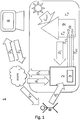
- Fig. 1 shows a first embodiment of a system 1 for calculating a set of optimized control parameters ⁇ or ⁇ k of a controller 3 or a controller 3 for an HVAC (heating, ventilation, air conditioning and refrigeration) system 2 with the characteristic signal flow according to the inventive method .
- the index k relates in each case to the current point in time and indicates that it is an iteratively optimized set of control parameters.
- the set of control parameters ⁇ without the running index k is used, for example, in the conventional least squares method without an iterative calculation method.
- a heating system 2 is considered below as an example of an HVAC system 2.
- the heating system 2 is installed in a building.
- an individual room 9 is considered as an example, the temperature T R of which is controlled by the heating system 2.
- This room 9 can also be used as a reference room for temperature control of the entire building. Alternatively, several reference rooms can be used, or temperature control can take place for each room in the building.
- the heating system 2 continuously records relevant system states such as the outside temperature T A , the room temperature T R , the flow temperature T VL , the return temperature T RL and the mass flow ⁇ of a carrier medium through a flow line or through a return line of the heating system 2 and transmits these measured values together as a data packet D k of the measurement time t k via the Internet to a server 8.
- the solar radiation G sol which contributes to the heating of the building or the room, can be recorded via a suitable sensor.
- the server 8 is designed to store and evaluate the received data packets D k , and thus to determine a set of optimized control parameters ⁇ k for a heating controller 3 of the heating system 2.
- the set of optimized control parameters ⁇ k can then be transmitted to a user B, for example to the heating engineer or the end customer. Then he has the possibility to decide to take over the control parameters ⁇ k .
- user B sets the control parameters ⁇ k on controller 3.
- the optimized control parameters ⁇ k can also be transmitted directly to the heating controller 3 via the Internet and taken over by the latter.
- the method according to the invention can thus also be used in heating regulators of older heating systems whose control parameters cannot be adjusted via the Internet.
- the central server 8 can also determine optimized control parameters of several different remote HVAC systems at the same time. For this purpose, the server 8 receives data packets from several HVAC systems, evaluates them and transmits the calculated, optimized control parameters to the respective user or controller.
- FIG. 2a a part of the system 1 for determining a set of optimized control parameters ⁇ k is shown.
- the system comprises several sensors for recording relevant system states.
- a flow temperature sensor 12 for detecting the flow temperature T VL arranged.
- a return temperature sensor 15 for detecting the return temperature T RL is arranged in the return of the heating system 2.
- a mass flow sensor for detecting the mass flow ⁇ can be arranged in the flow and / or return. in the room 9 arranged room temperature sensor 10 detects the room temperature T R.
- the heating system 2 supplies the flow with a carrier medium which transports heat to a heating element 16 arranged in the room 9.
- a desired room temperature T R , W can be specified via a thermostat 17 in room 9.
- an outside temperature sensor 11 for detecting the outside temperature T A and a solar radiation sensor 14 for detecting solar radiation G sol are arranged.
- at least one further sensor (not shown) for detecting an input of external heat source P FW can be arranged in the room.
- the source for an external heat source input P FW can be, for example, an electrical device that emits heat, such as a refrigerator or an electric stove.
- the controller 3 of the heating system 2 has a heating circuit controller 4 and a boiler controller 5. At least the recorded measured variables room temperature T R , outside temperature T A , target room temperature T R , W and flow temperature T VL are fed to the heating circuit controller 4. Optionally, at least one of the measured variables solar radiation G sol , mass flow ⁇ and / or external heat source input P FW can be fed to the heating circuit controller. On the basis of a control method specified for the heating controller 4, the heating controller 4 determines a target flow temperature T VL , W , which is output to a boiler controller 5. The control method used by the heating controller 4 can, for example, be based on a heating characteristic, as will be described in more detail below.
- Figure 2b illustrates the transmission of the measured values in the form of data packets D k to a server 8 for calculating optimized control parameters ⁇ k .
- the heating controller 3 comprises a device 22 for generating the data packet D k with the measured values and a point in time t k of the acquisition of the measured values. Via an interface 20 to the Internet, the data packet D k is transmitted to a server 8, which is also connected to the Internet via an interface 21.
- the server 8 comprises a buffer 6 in which the received data packet D k is initially temporarily stored, and a permanent memory 7 with a database in which the received data packets and calculated control parameters are stored.
- the server 8 also has a processor CPU which is configured to generate a set from the data packets to calculate the optimized control parameter ⁇ k.
- the set of optimized control parameters ⁇ k can then be transmitted again to the controller 4 or to a user of the heating system 2 via the interface 21.
- the heating controller 4 of the heating system 2 of the first exemplary embodiment can be regulated, for example, by means of a heating characteristic.
- the heating curve describes a relationship between the outside temperature T A and the setpoint of the flow temperature T VL , W of the heating system 2.
- a heating curve is characterized by the two parameters level ⁇ N and slope ⁇ S.
- Weather-compensated operation of the heating system 2 can be implemented with a heating characteristic.
- the system states flow temperature T VL , outside temperature T A and temperature in the reference room T R are determined using the corresponding in Fig. 2a temperature sensors 10, 11 and 12 shown.
- the target room temperature T R , W can be specified by a user, for example via the thermostat 17.
- Fig. 3 four exemplary heating characteristics a to d are shown for different values of the parameters inclination ⁇ S and level ⁇ N at a target room temperature T R , W of 20 ° C.
- the three heating curves a to c only differ in the parameter inclination ⁇ S. It can be seen that when the inclination ⁇ S increases (from a to c), the heating curve becomes steeper. A change in the parameter level ⁇ N shifts the characteristic in the vertical direction accordingly. This is shown as an example using the two heating curves c and d.
- the heating controller 4 uses the heating curve to calculate the set point of the flow temperature T VL, W, which as in Fig. 2a is passed on to the boiler controller 5.
- the two parameters slope and level of the heating characteristic can be set, for example, via a configuration menu on the heating controller.
- an installer of a heating system only sets the parameters when the heating system is commissioned, depending on the properties of the building.
- heating controllers are even operated with the parameters set in the delivery state.
- the parameters are usually only adjusted during ongoing heating operation if there is a significant deviation from the expected comfort of the heating system. To an undersupply with heat too avoid, heating systems are often operated with a higher flow temperature than necessary. This can lead to excessive energy consumption.
- the parameters inclination ⁇ S and level ⁇ N of the heating curve can be optimized with the system 1 according to the invention.
- the heating system 2 can thus be operated particularly efficiently. Excessive energy requirements or too little heat provided are avoided.
- the time-dependent measured values or setpoint values of the relevant state variables are recorded at regular time intervals and transmitted to the server 8 as data packets.
- the measured values can be displayed as data vectors that include all measured values of a time series.
- the measured values can be recorded over a period of one day with a resolution t S of 15 minutes, so that 96 data packets D 1 ... D 96 are generated and transmitted to the server in 24 hours.
- the server 8 can thus recalculate the optimized control parameters at regular time intervals t S.
- the control parameters can be calculated iteratively. This means that either the data packets from past times or previously calculated control parameters are used when calculating the control parameters.
- the advantage of the iterative approach is now illustrated by a comparison of a conventional method with the iterative calculation according to the invention.
- the calculation of the set of optimized control parameters can be done using known methods, for example. Two exemplary embodiments of the calculation method are described below.
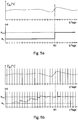
- measurement data must first be recorded over a long period of time.
- the lower diagram of the Figure 5a shows an initial value ⁇ 0 of the control parameters as well as the desired set of optimal control parameters ⁇ opt .
- the conventional method here takes 60 days to deliver a result.
- the large number of data packets can also make the calculation of the control parameters very time-consuming.
- the advantage of the iterative execution of the calculation of optimized control parameters is shown on the basis of Figure 5b described.
- the upper diagram again shows a course of the room temperature T R over a period of 60 days.
- the lower diagram corresponds to the course of the control parameters based on the same initial value ⁇ 0 , as well as the set of optimal control parameters ⁇ opt .
- a daily calculation of the set of optimized control parameters is carried out, in each case with transmitted and stored 96 data packets, as well as on the basis of the set of control parameters calculated the day before. This means that a much smaller amount of data has to be processed in the calculation.
- the data packets can be deleted again every day after the calculation of the optimized control parameters, so that there is a much smaller memory requirement compared to the conventional method.
- the result iteratively approaches the desired optimal set of control parameters. This means that the controller is activated much earlier than in the comparative example of the Figure 5a can be operated with optimized control parameters.
- the cost of the calculation is much lower.
- a first exemplary embodiment of a calculation algorithm for calculating a set of optimized control parameters uses a least squares method.
- the matrices A and b represent the so-called data matrices of the underlying estimation problem. Typically, more data points and thus rows of the data matrices are available as parameters to be estimated, so that the present system of linear equations is overdetermined.
- Such a conventional least-squares method is for example in Stoer / Bulirsch: Numerical Mathematics 1, Springer Verlag, Berlin, 2007, p. 25 off described.
- a heating curve is characterized by a set with the two parameters slope ⁇ S and level ⁇ N.
- the standard least squares method can be generalized even further by weighting the individual rows of the data matrices and thus the data points.
- Ljung, L . System Identification - Theory for the User, Prentice Hall, Upper Saddle River (1999 ) and R. Isermann and M. Münchhof: Identification of Dynamic Systems, Springer (2010 ) described.
- the weighted least squares method later forms the theoretical starting point for the application of the least squares method to the optimization of the heating curve.
- the division is to be interpreted, for example, in such a way that variables with the index k -1 represent the results of optimized control parameters from previous data packets (data packets up to point in time k -1).
- the index k thus indicates a newly generated data packet D k , which is used to update new control parameters ⁇ k .
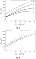
- Fig. 4 illustrates how a heating curve can be determined from the measured values.
- the measured values are plotted in a diagram.
- the plotted data points obtained from the measured values can also be filtered using a weighting function, so that only those data points are used for which the deviations e vL and / or e R are very small.
- the heating curve fitted to the data points then supplies the optimized control parameters ⁇ k , which can be transmitted to the heating controller 3.
- the setting parameters ⁇ VL and ⁇ R are essentially freely selectable. Depending on the amount of data packets available for the evaluation or depending on the scatter of the measured values, the setting parameters can be set larger or smaller in order to determine a set of optimized control parameters ⁇ k .
- the second exemplary embodiment deals with an explicit regulation of the temperature T R of a reference room 9 of a building.
- the second exemplary embodiment describes how a dynamic model M can be determined with the aid of the Internet and based on the stored data packets.
- Model M is a mathematical description of the relationships between the flow temperature T VL and the outside temperature T A on the room temperature T R. The model is determined based on the measured data.
- the data packets are generated and transmitted to a server 8 as described above with reference to the first exemplary embodiment. In the following, therefore, only the details of the mathematical method for calculating the optimized control parameters ⁇ k will be discussed.
- a mathematical building model enables the control parameters of a controller 3 of an HVAC system 2 to be optimized in a targeted manner, for example by means of a P, PI or PID controller, based on the model.
- the optimization can take place, for example, using standard control methods such as the root locus curve, frequency line method, etc.
- the parameters of the building model are determined and the optimized control parameters ⁇ k are calculated, as in the first exemplary embodiment, on a server 8 which communicates with the controller 3 via an Internet connection.
- the controller 3 itself works locally, for example in the heat generator of a heating system 2, and is automatically re-parameterized at regular intervals (for example daily, weekly or monthly).
- the control parameters are optimized using a model M of the controlled system.
- a calculation algorithm executed on the server 8 determines a mathematical relationship between the input and output data of the control process on the basis of the measurement data obtained, that is to say the data packets D k .
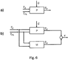
- FIG. 6a shows the initial situation with an exemplary process P, here a heating circuit.
- the outside temperature T A is a measurable disturbance variable.
- the flow temperature T VL of the heating circuit is the input variable.
- the room temperature T R is the output or controlled variable.
- the aim of the method is to determine a mathematical model M so that the output variable T ⁇ R supplied by the model M corresponds as precisely as possible to the measured room temperature T R corresponds to, as in Figure 6b shown schematically.
- the goal is therefore to minimize the deviation e between the output variable T ⁇ R and the measured room temperature T R.
- a time-discrete transfer function in the frequency range for the flow temperature G VL (Z) and a time-discrete transfer function for the outside temperature G A ( Z ) can be selected, from which T R.
- Z G VL Z ⁇ T VL Z + G A.
- the time-discrete transfer function in the frequency domain is expressed here as a time-discrete transfer function in the image area of a Z-transformation.
- N p is the number of poles of the transfer function and N Z, VL or N Z, A is the number of corresponding zeros. In principle, these can be freely selected, but can usually be determined in advance for physical reasons.
- the mathematical model M calculates the model output using historical values of the outside temperature T A and room temperature T R , which are stored as data packets in the storage medium 7 of the server 8.
- the matrices A and b can be generated from the data packets D i. If further disturbance variables are known, such as solar radiation G sol or an external heat source input P FW , the model can be expanded accordingly.
- the problem is converted into a least squares problem.
- the data packets D 1 to D N are used for this purpose.
- N 96 is assumed for one day.
- VL 1 N Z
- A. 1
- T R. k - a 1 T R. k - 1 - a 0 T R. k - 2 + b VL , 1 T VL k - 1 + b VL , 0 T VL k - 2 + b A. , 1 T A. k - 1 + b A. , 0 T A. k - 2
- T R. 1 ⁇ T R. N - a 1 T R. 0 - a 0 T R. - 1 + b VL , 1 T VL 0 + b VL , 0 T VL - 1 + b A. , 1 T A. 0 + b A. , 0 T A. - 1 ⁇ - a 1 T R. N - 1 - a 0 T R. N - 2 + b VL , 1 T VL N - 1 + b VL , 0 T VL N - 2 + b A. , 1 T A. N - 1 + b A. , 0 T A.
- the matrices A and b can therefore be generated from the data packets D i transmitted to the server 8.
- model M Since the parameters of model M are updated cyclically, for example daily, weekly or monthly, the result is an adaptive or optimized control of the heating system 2 that is adapted to the process (here a heating circuit) updated cyclically accordingly. A continuous, internet-based optimization of the controller 3 can thus take place.
- the advantage and innovation of the method is that there is no need to store and process the parameters on the embedded systems of the heat generator for the purpose of identifying the parameters, since these calculations are made on the corresponding capacities of the central platform on the Internet.
Landscapes
- Engineering & Computer Science (AREA)
- Physics & Mathematics (AREA)
- General Engineering & Computer Science (AREA)
- Automation & Control Theory (AREA)
- General Physics & Mathematics (AREA)
- Mechanical Engineering (AREA)
- Chemical & Material Sciences (AREA)
- Combustion & Propulsion (AREA)
- Fuzzy Systems (AREA)
- Mathematical Physics (AREA)
- Signal Processing (AREA)
- Remote Sensing (AREA)
- Air Conditioning Control Device (AREA)
Claims (10)
- Procédé pour établir un ensemble de paramètres de régulation optimisés (θ K ) d'un régulateur (3) ou d'une commande pour une installation CVCR (technique de chauffage, ventilation, climatisation et refroidissement) (2) avec les étapes suivantes consistant à :saisir une température extérieure (TA ) ;saisir une température ambiante réelle (TR ) d'une pièce (9) ;saisir une température de départ (TVL ) ;saisir une température ambiante de consigne (T R,W ) prédéfinie ;saisir une température de départ de consigne (TVL,W ) prédéfinie ;produire un paquet de données (DK ) avec lesdites températures (TA, TR , TVL ) saisies et températures de consigne (TR,W, TVL,W ) prédéfinies et un instant (tK ) de la saisie ;transmettre le paquet de données (DK ) à un serveur (8) via une liaison Internet ; etstocker le paquet de données (DK ) dans un support de stockage (6, 7) relié au serveur (8),caractérisé par le fait de :calculer un ensemble de paramètres de régulation optimisés (θK ) à l'aide des valeurs mesurées (TA, TR , TR,W, TVL, TVL,W ) du paquet de données (DK ) transmis et stocké et à l'aide :de valeurs mesurées (TA, TR , TR,W, TVL, TVL,W ) d'une pluralité d'autres paquets de données (D0...K ) produits en des instants antérieurs (t0...K ) d'une période (Δt) préétablie et/ouau moins de l'un d'une pluralité d'ensembles de paramètres de régulation optimisés établis précédemment (θ K-1) ;dans lequel le calcul de l'ensemble de paramètres de régulation optimisés (θ K ) s'effectue en exécutant un algorithme de calcul sur le serveur (8) ;stocker l'ensemble calculé de paramètres de régulation optimisés (θ K ) dans le support de stockage (6, 7) relié au serveur (8) ; ettransmettre l'ensemble calculé de paramètres de régulation optimisés (θ K ) depuis le serveur (8) vers le régulateur (3) ou la commande de l'installation CVCR (2) via la liaison Internet ou envoyer une notification avec l'ensemble calculé de paramètres de régulation optimisés (θK ) à un utilisateur (B) de l'installation CVCR (2).
- Procédé selon la revendication 1, dans lequel le procédé comprend en outre le fait de :
saisir au moins une autre valeur en l'instant (tK ) dans le groupe :température de retour (TRL ) ;débit massique (m) ;ensoleillement (Gsol) ;entrée de source de chaleur extérieure (PFW ) ;dans lequel le paquet de données (DK ) produit comprend la ou les autre(s) valeur(s) mesurée(s) (TRL, m, Gsol, PFW ) et l'algorithme de calcul établit l'ensemble de paramètres de régulation optimisés (θK ) au moins à l'aide des autres valeurs mesurées (TRL, m, Gsol, PFW ). - Procédé selon la revendication 1 ou 2, dans lequel la période (Δt) utilisée lors du calcul de l'ensemble de paramètres de régulation optimisés (θK ) est prédéfini en fonction du nombre de paquets de données (D0...K ) stockés dans le support de stockage (6, 7).
- Procédé selon au moins l'une des revendications précédentes, dans lequel le calcul de l'ensemble de paramètres de régulation optimisés (θK ) comprend le fait de :établir une première variation (eR ) entre la température ambiante réelle (TR ) et la température ambiante de consigne (TR, W ) pour chaque paquet de données (D 0...k ) d'une période (Δt) prédéfinie ;établir une seconde variation (eVL ) entre la température de départ (TVL ) et la température de départ prédéfinie (TVL,W ) pour chaque paquet de données (D 0...k ) de la période (Δt) prédéfinie ; etdéterminer et utiliser un facteur de pondération entre 0 et 1 en fonction des variations (eR , eVL ) établies, de sorte que lors du calcul de l'ensemble de paramètres de régulation optimisés (θK ) soient davantage pris en considération des paquets de données (D 0...k ) avec une variation faible et soient moins pris en considération des paquets de données (D 0...k ) avec une variation élevée ; oucalculer l'ensemble de paramètres de régulation optimisés (θK ) depuis des paquets de données (D 0...k ) stockés pour lesquels la première variation (e R ) établie et/ou la seconde variation (eVL ) établie est/sont inférieure(s) ou égale(s) à une valeur de seuil (δR, δVL ) respectivement prédéfinie.
- Procédé selon au moins l'une des revendications précédentes, dans lequel la saisie des valeurs mesurées est réalisée régulièrement après expiration d'un intervalle de temps prédéfini, et le calcul de l'ensemble de paramètres de régulation optimisés (θK ) est respectivement exécuté de façon récurrente dès lors qu'une pluralité prédéterminée d'intervalles de temps prédéfinis a expiré, de sorte qu'une pluralité correspondante de paquets de données (D 0...k ) produits pour le calcul de l'ensemble de paramètres de régulation optimisés (θK ) soit présente de façon stockée dans le support de stockage (6, 7) du serveur (8).
- Système (1) pour établir un ensemble de paramètres de régulation optimisés (θK ) d'un régulateur (3) ou d'une commande pour une installation CVCR (technique de chauffage, ventilation, climatisation et refroidissement) (2), comprenant :un capteur de température extérieure (11) pour saisir une température extérieure (TA ) ;un capteur de température ambiante (10) pour saisir une température ambiante réelle (TR ), qui est agencé dans une pièce (9) ;un capteur de température de départ (12) pour saisir une température de départ (TVL ) ;un dispositif (17) pour prédéfinir une température ambiante de consigne (T R,W ) ;un dispositif (4) pour prédéfinir une température de départ de consigne (T VL,W ) ;un dispositif (22) pour produire un paquet de données (DK ) avec lesdites températures (TA, TR , TVL ) saisies et températures de consigne (TR,W, TVL,W ) prédéfinies et un instant (tK ) de la saisie ;un dispositif de transmission avec une interface (20) pour transmettre le paquet de données (DK ) à un serveur (8) via une liaison Internet ; etun support de stockage (6, 7) relié au serveur (8) pour stocker le paquet de données (DK ),caractérisé en ce que le serveur (8) présente un processeur (CPU) qui est configuré pour :calculer un ensemble de paramètres de régulation optimisés (θK ) à l'aide de valeurs mesurées (TA, TR , TR, W, TVL, TVL,W ) du paquet de données (DK ) transmis et stocké de l'instant (tK ) et à l'aide :de valeurs mesurées (TA, TR , TR,W, TVL, TVL,W ) d'une pluralité d'autres paquets de données (D0...K-1 ) produits en des instants antérieurs (t0..K-1 ) d'une période (Δt) préétablie et/ouau moins de l'un d'une pluralité d'ensembles de paramètres de régulation optimisés établis précédemment (θ K-1) ;dans lequel le processeur (CPU) est configuré pour exécuter un algorithme de calcul afin de calculer l'ensemble de paramètres de régulation optimisés (θK ) ;stocker l'ensemble calculé de paramètres de régulation optimisés (θK ) dans le support de stockage (6, 7) relié au serveur (8) ; ettransmettre l'ensemble calculé de paramètres de régulation optimisés (θK ) vers le régulateur (3) ou la commande de l'installation CVCR (2) via une interface (21) via la liaison Internet ou envoyer une notification avec l'ensemble calculé de paramètres de régulation optimisés (θK ) à un utilisateur (B) de l'installation CVCR (2).
- Système (1) selon la revendication 6, dans lequel le système (1) comprend en outre :un capteur de température de retour (15) pour établir une température de retour (TRL) ; et/ouun capteur de débit massique (13) pour saisir un débit massique (m) ; et/ouun capteur d'ensoleillement (14) pour saisir un ensoleillement (Gsol ) ; et/ouun équipement pour saisir une entrée de source de chaleur extérieure (PFW ) ; et/oudans lequel le dispositif (22) pour produire un paquet de données est configuré pour produire le paquet de données (DK ) avec la/les autre(s) valeur (s) mesurée (s) (TRL, m, Gsol, PFW ) et le processeur (CPU) est conçu pour calculer l'ensemble de paramètres de régulation optimisés (θK ) au moins à l'aide de l'une des autres valeurs mesurées (TRL, m, Gsol, PFW ).
- Système (1) selon la revendication 6 ou 7, dans lequel le processeur (CPU) du serveur (8) est configuré pour prédéfinir la période (Δt) utilisée lors du calcul de l'ensemble de paramètres de régulation optimisés (θ K ) en fonction du nombre de paquets de données (D 0...K ) stockés.
- Système (1) selon au moins l'une des revendications 6 à 8, dans lequel le processeur (CPU) du serveur (8) est configuré pour :établir une première variation (e R ) entre la température ambiante réelle (TR ) et la température ambiante de consigne (T R,W ) pour chaque paquet de données (D 0...K ) d'une période (Δt) prédéfinie ;établir une seconde variation (eVL ) entre la température de départ (TVL ) et la température de départ prédéfinie (TVL,W ) pour chaque paquet de données (D 0...K ) de la période (Δt) prédéfinie ; etdéterminer et utiliser un facteur de pondération entre 0 et 1 en fonction des variations (eR , eVL ) établies, de sorte que lors du calcul de l'ensemble de paramètres de régulation optimisés (θ K ) soient davantage pris en considération des paquets de données (D 0...K ) avec une variation faible et soient moins pris en considération des paquets de données (D 0...K ) avec une variation élevée ; ouétablir l'ensemble de paramètres de régulation optimisés (θK ) depuis les paquets de données (D 0...K ) stockés pour lesquels la première variation (e R ) établie et/ou la seconde variation (eVL ) établie est inférieure ou égale à une valeur de seuil (δR, δ VL ) respectivement prédéfinie.
- Système (1) selon au moins l'une des revendications 6 à 9, dans lequel les capteurs saisissent les valeurs mesurées régulièrement après expiration d'un intervalle de temps prédéfini, et le processeur (CPU) du serveur (8) est configuré pour respectivement calculer l'ensemble de paramètres de régulation optimisés (θ K ) de façon récurrente dès lors qu'une pluralité prédéterminée d'intervalles de temps prédéfinis a expiré, de sorte qu'une pluralité correspondante de paquets de données (D0...K) produits pour le calcul de l'ensemble de paramètres de régulation optimisés (θ K ) soit présente de façon stockée dans le support de stockage (6, 7) du serveur (8).
Applications Claiming Priority (2)
| Application Number | Priority Date | Filing Date | Title |
|---|---|---|---|
| DE102017205033.0A DE102017205033B4 (de) | 2017-03-24 | 2017-03-24 | Verfahren und System zum internetgestützten Optimieren von Parametern einer Heizungsregelung |
| PCT/EP2018/052796 WO2018171969A1 (fr) | 2017-03-24 | 2018-02-05 | Procédé et dispositif d'optimisation, basée sur internet, de paramètres d'une régulation de chauffage |
Publications (2)
| Publication Number | Publication Date |
|---|---|
| EP3602229A1 EP3602229A1 (fr) | 2020-02-05 |
| EP3602229B1 true EP3602229B1 (fr) | 2021-05-05 |
Family
ID=61168109
Family Applications (1)
| Application Number | Title | Priority Date | Filing Date |
|---|---|---|---|
| EP18703577.9A Active EP3602229B1 (fr) | 2017-03-24 | 2018-02-05 | Procédé et dispositif d'optimisation, basée sur internet, de paramètres d'une régulation de chauffage |
Country Status (5)
| Country | Link |
|---|---|
| US (1) | US11306933B2 (fr) |
| EP (1) | EP3602229B1 (fr) |
| CN (1) | CN110709796B (fr) |
| DE (1) | DE102017205033B4 (fr) |
| WO (1) | WO2018171969A1 (fr) |
Families Citing this family (8)
| Publication number | Priority date | Publication date | Assignee | Title |
|---|---|---|---|---|
| CN110543196B (zh) * | 2019-08-13 | 2021-02-12 | 华为技术有限公司 | 一种散热元件的控制方法及控制装置 |
| US20230161929A1 (en) * | 2020-04-06 | 2023-05-25 | Nippon Telegraph And Telephone Corporation | Estimation method, simulation method, estimation device, and estimation program |
| CN111854109A (zh) * | 2020-06-11 | 2020-10-30 | 深圳市合信达控制系统有限公司 | 一种室内温度控制方法、装置、电子设备及存储介质 |
| CN111880419A (zh) * | 2020-06-29 | 2020-11-03 | 深圳市合信达控制系统有限公司 | 家电设备的控制方法、系统、家电设备及运算设备 |
| CN112526879A (zh) * | 2020-11-23 | 2021-03-19 | 珠海格力电器股份有限公司 | 温控系统的参数确定方法、装置、控制方法、系统及介质 |
| DE102021200129A1 (de) * | 2021-01-08 | 2022-07-14 | Viessmann Climate Solutions Se | Verfahren zum optimieren einer heizkurve und heizungssystem |
| DE102021117487A1 (de) | 2021-07-07 | 2023-01-12 | Techem Energy Services Gmbh | Verfahren und Vorrichtung zum Ermitteln einer Heizungskennlinie und Heizungsanlage mit dieser Vorrichtung |
| SE545541C2 (en) * | 2021-12-14 | 2023-10-17 | Energy Cut Sweden AB | Device and a method related to control of a heating source |
Citations (5)
| Publication number | Priority date | Publication date | Assignee | Title |
|---|---|---|---|---|
| US20130073094A1 (en) | 2010-03-30 | 2013-03-21 | Telepure Limited | Building occupancy dependent control system |
| CH705980A2 (fr) | 2012-01-12 | 2013-07-15 | Neurobat Ag | Système de régulation de la température dans une installation de chauffage d'un immeuble. |
| DE102012215368A1 (de) | 2012-08-30 | 2014-03-06 | Martin Donath | Verfahren zur energetischen, tagesaktuellen Permanentanalyse von gebäudetechnischen Anlagen |
| US20160047568A1 (en) | 2014-08-15 | 2016-02-18 | Delta Electronics, Inc. | Intelligent air-conditioning controlling system and intelligent controlling method for the same |
| US20160246269A1 (en) | 2015-02-24 | 2016-08-25 | Siemens Industry, Inc. | Variable air volume modeling for an hvac system |
Family Cites Families (14)
| Publication number | Priority date | Publication date | Assignee | Title |
|---|---|---|---|---|
| FR2782375B1 (fr) | 1998-08-13 | 2000-10-06 | Suisse Electronique Microtech | Systeme de regulation du chauffage d'un immeuble |
| US20150276253A1 (en) * | 2008-10-08 | 2015-10-01 | Rey Montalvo | Method and system for fully automated enterprise control of local power usage |
| KR20120089654A (ko) * | 2009-08-21 | 2012-08-13 | 비질런트 코포레이션 | 데이터 센터 냉각 유닛을 효율적으로 조정하는 방법 및 장치 |
| AU2010333708B2 (en) * | 2009-12-16 | 2015-06-11 | Commonwealth Scientific And Industrial Research Organisation | HVAC control system and method |
| CH705804A1 (de) | 2011-11-28 | 2013-05-31 | Belimo Holding Ag | Verfahren zur Regelung der Raumtemperatur in einem Raum oder einer Gruppe von mehreren Räumen sowie eine Vorrichtung zur Durchführung des Verfahrens. |
| US20130201316A1 (en) * | 2012-01-09 | 2013-08-08 | May Patents Ltd. | System and method for server based control |
| US9582009B2 (en) | 2012-04-30 | 2017-02-28 | SmrtEn, LLC | System and method for optimizing and reducing the energy usage of an automatically controlled HVAC system |
| US9958190B2 (en) * | 2013-01-24 | 2018-05-01 | Advantek Consulting Engineering, Inc. | Optimizing energy efficiency ratio feedback control for direct expansion air-conditioners and heat pumps |
| US9625274B2 (en) * | 2014-03-28 | 2017-04-18 | Mitsubishi Electric Research Laboratories, Inc. | Time-varying extremum seeking for controlling vapor compression systems |
| US9772633B2 (en) * | 2014-08-27 | 2017-09-26 | Schneider Electric Buildings, Llc | Systems and methods for controlling energy input into a building |
| US20160283844A1 (en) * | 2015-03-27 | 2016-09-29 | Optimum Energy Llc | Load predictor for a cooling system |
| US10761547B2 (en) | 2015-04-23 | 2020-09-01 | Johnson Controls Technology Company | HVAC controller with integrated airside and waterside cost optimization |
| US9482442B1 (en) * | 2015-04-24 | 2016-11-01 | Dataxu, Inc. | Decision dashboard balancing competing objectives |
| US10739027B2 (en) * | 2015-06-24 | 2020-08-11 | Emerson Electric Co. | HVAC performance and energy usage monitoring and reporting system |
-
2017
- 2017-03-24 DE DE102017205033.0A patent/DE102017205033B4/de active Active
-
2018
- 2018-02-05 WO PCT/EP2018/052796 patent/WO2018171969A1/fr active Application Filing
- 2018-02-05 CN CN201880024742.4A patent/CN110709796B/zh active Active
- 2018-02-05 EP EP18703577.9A patent/EP3602229B1/fr active Active
- 2018-02-05 US US16/496,108 patent/US11306933B2/en active Active
Patent Citations (5)
| Publication number | Priority date | Publication date | Assignee | Title |
|---|---|---|---|---|
| US20130073094A1 (en) | 2010-03-30 | 2013-03-21 | Telepure Limited | Building occupancy dependent control system |
| CH705980A2 (fr) | 2012-01-12 | 2013-07-15 | Neurobat Ag | Système de régulation de la température dans une installation de chauffage d'un immeuble. |
| DE102012215368A1 (de) | 2012-08-30 | 2014-03-06 | Martin Donath | Verfahren zur energetischen, tagesaktuellen Permanentanalyse von gebäudetechnischen Anlagen |
| US20160047568A1 (en) | 2014-08-15 | 2016-02-18 | Delta Electronics, Inc. | Intelligent air-conditioning controlling system and intelligent controlling method for the same |
| US20160246269A1 (en) | 2015-02-24 | 2016-08-25 | Siemens Industry, Inc. | Variable air volume modeling for an hvac system |
Non-Patent Citations (5)
| Title |
|---|
| DAVID J. GILLILAND ET AL.: "A Field Evaluation of Cloud-Based Predic- tive HVAC Control Software - The Next Step in Energy Efficiency, or Marketing Mumbo Jumbo?", ACEEE SUMMER STUDY ON ENERGY EFFICIENCY IN BUILDINGS, 2016, XP055895951 |
| JAVED A. ET AL.: "Smart Random Neural Network Controller for HVAC Using Cloud Computing Technology", IEEE TRANSACTIONS ON INDUSTRIAL IN - FORMATICS, vol. 13, no. 1, February 2017 (2017-02-01), pages 351 - 360, XP011641041, DOI: 10.1109/TII.2016.2597746 |
| LINDELÖF, D. ET AL.: "ARCHITECTURE AND FIELD TEST OF A RESTFUL WEB SERVICE FOR THE OPTIMISATION OF SPACE HEATING IN A COMMER- CIAL OFFICE", PROCEEDINGS OF CISBAT 2015 INTERNATIONAL CONFERENCE ON FU- TURE BUILDINGS AND DISTRICTS - SUSTAINABILITY FROM NANO TO URBAN SCALE, vol. I, 2015, pages 969 - 974, XP055895958 |
| LINDELÖF, D. ET AL.: "FIELD TESTS OF AN ADAPTIVE MODEL-PREDICTIVE HEATING CONTROL SYSTEM", PROCEEDINGS OF CISBAT 2015 INTERNATIONAL CONFERENCE ON FUTURE BUILDINGS AND DISTRICTS - SUSTAINABILITY FROM NANO TO UR- BAN SCALE, vol. I, 2015, pages 413 - 418, XP055895960 |
| LINDELÖF, D. ET AL.: "Field tests of an adaptive, model-predictive heating controller for residential buildings", ENERGY AND BUILDINGS, vol. 99, 2015, pages 292 - 302, XP055895965 |
Also Published As
| Publication number | Publication date |
|---|---|
| WO2018171969A1 (fr) | 2018-09-27 |
| US20200096215A1 (en) | 2020-03-26 |
| DE102017205033B4 (de) | 2024-02-08 |
| US11306933B2 (en) | 2022-04-19 |
| CN110709796B (zh) | 2021-03-19 |
| DE102017205033A1 (de) | 2018-09-27 |
| CN110709796A (zh) | 2020-01-17 |
| EP3602229A1 (fr) | 2020-02-05 |
Similar Documents
| Publication | Publication Date | Title |
|---|---|---|
| EP3602229B1 (fr) | Procédé et dispositif d'optimisation, basée sur internet, de paramètres d'une régulation de chauffage | |
| DE10312825B4 (de) | Verfahren zum Einstellen mehrerer parallel geschalteter Wärmetauscher | |
| DE69618637T2 (de) | Thermostatsystem mit optimierter ansteigsrate der wiederzuerreichenden temperatur | |
| DE3685664T2 (de) | Temperatursteuerungssystem. | |
| EP1645928B1 (fr) | Procédé de détermination de l'état d'alimentation d'une surface chauffante et régulateur d'état d'alimentation | |
| EP3936770A1 (fr) | Système de chauffage à équilibrage hydraulique adaptatif automatique | |
| CH707678A1 (de) | Verfahren und System zum Temperieren von Bauteilen. | |
| EP1777465A2 (fr) | Méthode pour la détermination de la demande de chaleur d'un bâtiment | |
| DE102007030492A1 (de) | Gebäudemodellbasiertes prädiktives Regelverfahren zum Heizen eines begrenzten Systems | |
| EP3474112A2 (fr) | Procédé de détermination d'une courbe de température attendue ainsi que procédé de détermination d'un programme de chauffage et / ou de refroidissement d'un système de chauffage et / ou de refroidissement | |
| EP2009536B1 (fr) | Procédé et dispositif destinés à l'ajustage de la réserve de puissance de chauffe | |
| EP3412978A1 (fr) | Procédé de commande d'un système de refroidissement et/ou de chauffage | |
| DE3300082C2 (fr) | ||
| EP3026507A1 (fr) | Procede de reglage d'une grandeur d'etat reglable par une installation domotique | |
| EP3542229B1 (fr) | Dispositif et procédé de détermination des paramètres d'un dispositif de réglage | |
| DE102014014325A1 (de) | Wärmepumpenvorrichtung und Verfahren zum Steuern einer Wärmepumpenvorrichtung | |
| DE10132113B4 (de) | Verfahren zur Ermittlung des Ertrags von Solarthermieanlagen | |
| EP3521947A1 (fr) | Procédé de gestion de l'énergie | |
| EP3168540A1 (fr) | Procédé d'exécution d'un équilibrage hydraulique automatisé, soupape et installation de chauffage associées | |
| DE19600694A1 (de) | Klimaregelungssystem | |
| EP3483513B1 (fr) | Procédé de fonctionnement d'une installation de chauffage et installation de chauffage | |
| DE4337388C2 (de) | Verfahren zur außentemperaturgeführten Steuerung/Regelung eines Heizgerätes sowie Vorrichtung zur Durchführung des Verfahrens | |
| DE102005057769B4 (de) | Temperatur-Steuervorrichtung und Verfahren zum Betreiben eines Heiz- und/oder Kühlsystems | |
| EP3709122B1 (fr) | Dispositif de régulation de température des pièces d'un bâtiment et procédé de régulation associé | |
| DE102014202311A1 (de) | Verfahren zum Synchronisieren einer Thermoanlage mit einem Thermosystem |
Legal Events
| Date | Code | Title | Description |
|---|---|---|---|
| STAA | Information on the status of an ep patent application or granted ep patent |
Free format text: STATUS: UNKNOWN |
|
| STAA | Information on the status of an ep patent application or granted ep patent |
Free format text: STATUS: THE INTERNATIONAL PUBLICATION HAS BEEN MADE |
|
| PUAI | Public reference made under article 153(3) epc to a published international application that has entered the european phase |
Free format text: ORIGINAL CODE: 0009012 |
|
| STAA | Information on the status of an ep patent application or granted ep patent |
Free format text: STATUS: REQUEST FOR EXAMINATION WAS MADE |
|
| 17P | Request for examination filed |
Effective date: 20191024 |
|
| AK | Designated contracting states |
Kind code of ref document: A1 Designated state(s): AL AT BE BG CH CY CZ DE DK EE ES FI FR GB GR HR HU IE IS IT LI LT LU LV MC MK MT NL NO PL PT RO RS SE SI SK SM TR |
|
| AX | Request for extension of the european patent |
Extension state: BA ME |
|
| DAV | Request for validation of the european patent (deleted) | ||
| DAX | Request for extension of the european patent (deleted) | ||
| REG | Reference to a national code |
Ref country code: DE Ref legal event code: R079 Ref document number: 502018005113 Country of ref document: DE Free format text: PREVIOUS MAIN CLASS: G05D0023190000 Ipc: G05B0015020000 |
|
| STAA | Information on the status of an ep patent application or granted ep patent |
Free format text: STATUS: EXAMINATION IS IN PROGRESS |
|
| RIC1 | Information provided on ipc code assigned before grant |
Ipc: G05D 23/19 20060101ALI20200831BHEP Ipc: G05B 15/02 20060101AFI20200831BHEP |
|
| 17Q | First examination report despatched |
Effective date: 20200924 |
|
| GRAP | Despatch of communication of intention to grant a patent |
Free format text: ORIGINAL CODE: EPIDOSNIGR1 |
|
| STAA | Information on the status of an ep patent application or granted ep patent |
Free format text: STATUS: GRANT OF PATENT IS INTENDED |
|
| INTG | Intention to grant announced |
Effective date: 20201201 |
|
| RAP1 | Party data changed (applicant data changed or rights of an application transferred) |
Owner name: VIESSMANN CLIMATE SOLUTIONS SE |
|
| GRAS | Grant fee paid |
Free format text: ORIGINAL CODE: EPIDOSNIGR3 |
|
| GRAA | (expected) grant |
Free format text: ORIGINAL CODE: 0009210 |
|
| STAA | Information on the status of an ep patent application or granted ep patent |
Free format text: STATUS: THE PATENT HAS BEEN GRANTED |
|
| AK | Designated contracting states |
Kind code of ref document: B1 Designated state(s): AL AT BE BG CH CY CZ DE DK EE ES FI FR GB GR HR HU IE IS IT LI LT LU LV MC MK MT NL NO PL PT RO RS SE SI SK SM TR |
|
| REG | Reference to a national code |
Ref country code: GB Ref legal event code: FG4D Free format text: NOT ENGLISH |
|
| REG | Reference to a national code |
Ref country code: CH Ref legal event code: EP |
|
| REG | Reference to a national code |
Ref country code: AT Ref legal event code: REF Ref document number: 1390584 Country of ref document: AT Kind code of ref document: T Effective date: 20210515 |
|
| REG | Reference to a national code |
Ref country code: DE Ref legal event code: R096 Ref document number: 502018005113 Country of ref document: DE |
|
| REG | Reference to a national code |
Ref country code: IE Ref legal event code: FG4D Free format text: LANGUAGE OF EP DOCUMENT: GERMAN |
|
| REG | Reference to a national code |
Ref country code: NL Ref legal event code: FP |
|
| REG | Reference to a national code |
Ref country code: SE Ref legal event code: TRGR |
|
| REG | Reference to a national code |
Ref country code: LT Ref legal event code: MG9D |
|
| PG25 | Lapsed in a contracting state [announced via postgrant information from national office to epo] |
Ref country code: FI Free format text: LAPSE BECAUSE OF FAILURE TO SUBMIT A TRANSLATION OF THE DESCRIPTION OR TO PAY THE FEE WITHIN THE PRESCRIBED TIME-LIMIT Effective date: 20210505 Ref country code: HR Free format text: LAPSE BECAUSE OF FAILURE TO SUBMIT A TRANSLATION OF THE DESCRIPTION OR TO PAY THE FEE WITHIN THE PRESCRIBED TIME-LIMIT Effective date: 20210505 Ref country code: LT Free format text: LAPSE BECAUSE OF FAILURE TO SUBMIT A TRANSLATION OF THE DESCRIPTION OR TO PAY THE FEE WITHIN THE PRESCRIBED TIME-LIMIT Effective date: 20210505 Ref country code: BG Free format text: LAPSE BECAUSE OF FAILURE TO SUBMIT A TRANSLATION OF THE DESCRIPTION OR TO PAY THE FEE WITHIN THE PRESCRIBED TIME-LIMIT Effective date: 20210805 |
|
| PG25 | Lapsed in a contracting state [announced via postgrant information from national office to epo] |
Ref country code: IS Free format text: LAPSE BECAUSE OF FAILURE TO SUBMIT A TRANSLATION OF THE DESCRIPTION OR TO PAY THE FEE WITHIN THE PRESCRIBED TIME-LIMIT Effective date: 20210905 Ref country code: GR Free format text: LAPSE BECAUSE OF FAILURE TO SUBMIT A TRANSLATION OF THE DESCRIPTION OR TO PAY THE FEE WITHIN THE PRESCRIBED TIME-LIMIT Effective date: 20210806 Ref country code: NO Free format text: LAPSE BECAUSE OF FAILURE TO SUBMIT A TRANSLATION OF THE DESCRIPTION OR TO PAY THE FEE WITHIN THE PRESCRIBED TIME-LIMIT Effective date: 20210805 Ref country code: PT Free format text: LAPSE BECAUSE OF FAILURE TO SUBMIT A TRANSLATION OF THE DESCRIPTION OR TO PAY THE FEE WITHIN THE PRESCRIBED TIME-LIMIT Effective date: 20210906 Ref country code: LV Free format text: LAPSE BECAUSE OF FAILURE TO SUBMIT A TRANSLATION OF THE DESCRIPTION OR TO PAY THE FEE WITHIN THE PRESCRIBED TIME-LIMIT Effective date: 20210505 Ref country code: PL Free format text: LAPSE BECAUSE OF FAILURE TO SUBMIT A TRANSLATION OF THE DESCRIPTION OR TO PAY THE FEE WITHIN THE PRESCRIBED TIME-LIMIT Effective date: 20210505 Ref country code: RS Free format text: LAPSE BECAUSE OF FAILURE TO SUBMIT A TRANSLATION OF THE DESCRIPTION OR TO PAY THE FEE WITHIN THE PRESCRIBED TIME-LIMIT Effective date: 20210505 |
|
| PG25 | Lapsed in a contracting state [announced via postgrant information from national office to epo] |
Ref country code: SM Free format text: LAPSE BECAUSE OF FAILURE TO SUBMIT A TRANSLATION OF THE DESCRIPTION OR TO PAY THE FEE WITHIN THE PRESCRIBED TIME-LIMIT Effective date: 20210505 Ref country code: SK Free format text: LAPSE BECAUSE OF FAILURE TO SUBMIT A TRANSLATION OF THE DESCRIPTION OR TO PAY THE FEE WITHIN THE PRESCRIBED TIME-LIMIT Effective date: 20210505 Ref country code: ES Free format text: LAPSE BECAUSE OF FAILURE TO SUBMIT A TRANSLATION OF THE DESCRIPTION OR TO PAY THE FEE WITHIN THE PRESCRIBED TIME-LIMIT Effective date: 20210505 Ref country code: EE Free format text: LAPSE BECAUSE OF FAILURE TO SUBMIT A TRANSLATION OF THE DESCRIPTION OR TO PAY THE FEE WITHIN THE PRESCRIBED TIME-LIMIT Effective date: 20210505 Ref country code: RO Free format text: LAPSE BECAUSE OF FAILURE TO SUBMIT A TRANSLATION OF THE DESCRIPTION OR TO PAY THE FEE WITHIN THE PRESCRIBED TIME-LIMIT Effective date: 20210505 Ref country code: CZ Free format text: LAPSE BECAUSE OF FAILURE TO SUBMIT A TRANSLATION OF THE DESCRIPTION OR TO PAY THE FEE WITHIN THE PRESCRIBED TIME-LIMIT Effective date: 20210505 Ref country code: DK Free format text: LAPSE BECAUSE OF FAILURE TO SUBMIT A TRANSLATION OF THE DESCRIPTION OR TO PAY THE FEE WITHIN THE PRESCRIBED TIME-LIMIT Effective date: 20210505 |
|
| REG | Reference to a national code |
Ref country code: DE Ref legal event code: R026 Ref document number: 502018005113 Country of ref document: DE |
|
| PLBI | Opposition filed |
Free format text: ORIGINAL CODE: 0009260 |
|
| PLAX | Notice of opposition and request to file observation + time limit sent |
Free format text: ORIGINAL CODE: EPIDOSNOBS2 |
|
| 26 | Opposition filed |
Opponent name: STIEBEL ELTRON GMBH & CO. KG Effective date: 20220207 |
|
| PG25 | Lapsed in a contracting state [announced via postgrant information from national office to epo] |
Ref country code: IS Free format text: LAPSE BECAUSE OF FAILURE TO SUBMIT A TRANSLATION OF THE DESCRIPTION OR TO PAY THE FEE WITHIN THE PRESCRIBED TIME-LIMIT Effective date: 20210905 Ref country code: AL Free format text: LAPSE BECAUSE OF FAILURE TO SUBMIT A TRANSLATION OF THE DESCRIPTION OR TO PAY THE FEE WITHIN THE PRESCRIBED TIME-LIMIT Effective date: 20210505 |
|
| PLBB | Reply of patent proprietor to notice(s) of opposition received |
Free format text: ORIGINAL CODE: EPIDOSNOBS3 |
|
| PG25 | Lapsed in a contracting state [announced via postgrant information from national office to epo] |
Ref country code: MC Free format text: LAPSE BECAUSE OF FAILURE TO SUBMIT A TRANSLATION OF THE DESCRIPTION OR TO PAY THE FEE WITHIN THE PRESCRIBED TIME-LIMIT Effective date: 20210505 |
|
| REG | Reference to a national code |
Ref country code: BE Ref legal event code: MM Effective date: 20220228 |
|
| PG25 | Lapsed in a contracting state [announced via postgrant information from national office to epo] |
Ref country code: LU Free format text: LAPSE BECAUSE OF NON-PAYMENT OF DUE FEES Effective date: 20220205 |
|
| PLBP | Opposition withdrawn |
Free format text: ORIGINAL CODE: 0009264 |
|
| PG25 | Lapsed in a contracting state [announced via postgrant information from national office to epo] |
Ref country code: IE Free format text: LAPSE BECAUSE OF NON-PAYMENT OF DUE FEES Effective date: 20220205 |
|
| PLBD | Termination of opposition procedure: decision despatched |
Free format text: ORIGINAL CODE: EPIDOSNOPC1 |
|
| REG | Reference to a national code |
Ref country code: DE Ref legal event code: R100 Ref document number: 502018005113 Country of ref document: DE |
|
| PG25 | Lapsed in a contracting state [announced via postgrant information from national office to epo] |
Ref country code: BE Free format text: LAPSE BECAUSE OF NON-PAYMENT OF DUE FEES Effective date: 20220228 |
|
| PGFP | Annual fee paid to national office [announced via postgrant information from national office to epo] |
Ref country code: AT Payment date: 20230215 Year of fee payment: 6 |
|
| PLBM | Termination of opposition procedure: date of legal effect published |
Free format text: ORIGINAL CODE: 0009276 |
|
| PGFP | Annual fee paid to national office [announced via postgrant information from national office to epo] |
Ref country code: SE Payment date: 20230220 Year of fee payment: 6 |
|
| P01 | Opt-out of the competence of the unified patent court (upc) registered |
Effective date: 20230515 |
|
| 27C | Opposition proceedings terminated |
Effective date: 20230220 |
|
| PGFP | Annual fee paid to national office [announced via postgrant information from national office to epo] |
Ref country code: NL Payment date: 20240220 Year of fee payment: 7 |
|
| PG25 | Lapsed in a contracting state [announced via postgrant information from national office to epo] |
Ref country code: MK Free format text: LAPSE BECAUSE OF FAILURE TO SUBMIT A TRANSLATION OF THE DESCRIPTION OR TO PAY THE FEE WITHIN THE PRESCRIBED TIME-LIMIT Effective date: 20210505 Ref country code: CY Free format text: LAPSE BECAUSE OF FAILURE TO SUBMIT A TRANSLATION OF THE DESCRIPTION OR TO PAY THE FEE WITHIN THE PRESCRIBED TIME-LIMIT Effective date: 20210505 |
|
| PGFP | Annual fee paid to national office [announced via postgrant information from national office to epo] |
Ref country code: DE Payment date: 20240229 Year of fee payment: 7 Ref country code: GB Payment date: 20240222 Year of fee payment: 7 Ref country code: CH Payment date: 20240301 Year of fee payment: 7 |
|
| PG25 | Lapsed in a contracting state [announced via postgrant information from national office to epo] |
Ref country code: HU Free format text: LAPSE BECAUSE OF FAILURE TO SUBMIT A TRANSLATION OF THE DESCRIPTION OR TO PAY THE FEE WITHIN THE PRESCRIBED TIME-LIMIT; INVALID AB INITIO Effective date: 20180205 |
|
| PGFP | Annual fee paid to national office [announced via postgrant information from national office to epo] |
Ref country code: IT Payment date: 20240229 Year of fee payment: 7 Ref country code: FR Payment date: 20240222 Year of fee payment: 7 |