EP3602229B1 - Method and device for internet-supported optimization of the parameters of heating control - Google Patents
Method and device for internet-supported optimization of the parameters of heating control Download PDFInfo
- Publication number
- EP3602229B1 EP3602229B1 EP18703577.9A EP18703577A EP3602229B1 EP 3602229 B1 EP3602229 B1 EP 3602229B1 EP 18703577 A EP18703577 A EP 18703577A EP 3602229 B1 EP3602229 B1 EP 3602229B1
- Authority
- EP
- European Patent Office
- Prior art keywords
- control parameters
- optimized control
- server
- data packet
- data packets
- Prior art date
- Legal status (The legal status is an assumption and is not a legal conclusion. Google has not performed a legal analysis and makes no representation as to the accuracy of the status listed.)
- Active
Links
- 238000010438 heat treatment Methods 0.000 title claims description 123
- 238000000034 method Methods 0.000 title claims description 62
- 238000005457 optimization Methods 0.000 title description 11
- 238000005259 measurement Methods 0.000 claims description 19
- 238000004422 calculation algorithm Methods 0.000 claims description 15
- 238000004378 air conditioning Methods 0.000 claims description 6
- 238000005057 refrigeration Methods 0.000 claims description 6
- 238000009423 ventilation Methods 0.000 claims description 6
- 230000005540 biological transmission Effects 0.000 claims description 4
- 238000001514 detection method Methods 0.000 claims 2
- 230000001419 dependent effect Effects 0.000 claims 1
- 238000004364 calculation method Methods 0.000 description 17
- 230000005855 radiation Effects 0.000 description 15
- 230000006870 function Effects 0.000 description 14
- 230000008569 process Effects 0.000 description 12
- 238000012546 transfer Methods 0.000 description 9
- 238000013459 approach Methods 0.000 description 6
- 238000010586 diagram Methods 0.000 description 6
- 238000007796 conventional method Methods 0.000 description 4
- 230000002354 daily effect Effects 0.000 description 4
- 238000013178 mathematical model Methods 0.000 description 4
- 230000001105 regulatory effect Effects 0.000 description 4
- 230000008901 benefit Effects 0.000 description 3
- 238000005265 energy consumption Methods 0.000 description 3
- 239000013598 vector Substances 0.000 description 3
- 230000006978 adaptation Effects 0.000 description 2
- 230000003044 adaptive effect Effects 0.000 description 2
- 238000013528 artificial neural network Methods 0.000 description 2
- 238000001816 cooling Methods 0.000 description 2
- 230000000694 effects Effects 0.000 description 2
- 238000009472 formulation Methods 0.000 description 2
- 239000000203 mixture Substances 0.000 description 2
- 238000012545 processing Methods 0.000 description 2
- 238000005070 sampling Methods 0.000 description 2
- 230000003442 weekly effect Effects 0.000 description 2
- 241000127225 Enceliopsis nudicaulis Species 0.000 description 1
- 230000009471 action Effects 0.000 description 1
- 230000008859 change Effects 0.000 description 1
- 230000000052 comparative effect Effects 0.000 description 1
- 230000001276 controlling effect Effects 0.000 description 1
- 238000005516 engineering process Methods 0.000 description 1
- 238000011156 evaluation Methods 0.000 description 1
- 230000003203 everyday effect Effects 0.000 description 1
- 230000007774 longterm Effects 0.000 description 1
- 238000012067 mathematical method Methods 0.000 description 1
- 239000011159 matrix material Substances 0.000 description 1
- 238000010561 standard procedure Methods 0.000 description 1
- 230000003068 static effect Effects 0.000 description 1
- 230000036962 time dependent Effects 0.000 description 1
- 238000013519 translation Methods 0.000 description 1
- 230000032258 transport Effects 0.000 description 1
Images

Classifications
-
- F—MECHANICAL ENGINEERING; LIGHTING; HEATING; WEAPONS; BLASTING
- F24—HEATING; RANGES; VENTILATING
- F24F—AIR-CONDITIONING; AIR-HUMIDIFICATION; VENTILATION; USE OF AIR CURRENTS FOR SCREENING
- F24F11/00—Control or safety arrangements
- F24F11/30—Control or safety arrangements for purposes related to the operation of the system, e.g. for safety or monitoring
-
- G—PHYSICS
- G05—CONTROLLING; REGULATING
- G05D—SYSTEMS FOR CONTROLLING OR REGULATING NON-ELECTRIC VARIABLES
- G05D23/00—Control of temperature
- G05D23/19—Control of temperature characterised by the use of electric means
- G05D23/1917—Control of temperature characterised by the use of electric means using digital means
-
- F—MECHANICAL ENGINEERING; LIGHTING; HEATING; WEAPONS; BLASTING
- F24—HEATING; RANGES; VENTILATING
- F24F—AIR-CONDITIONING; AIR-HUMIDIFICATION; VENTILATION; USE OF AIR CURRENTS FOR SCREENING
- F24F11/00—Control or safety arrangements
- F24F11/62—Control or safety arrangements characterised by the type of control or by internal processing, e.g. using fuzzy logic, adaptive control or estimation of values
-
- G—PHYSICS
- G05—CONTROLLING; REGULATING
- G05B—CONTROL OR REGULATING SYSTEMS IN GENERAL; FUNCTIONAL ELEMENTS OF SUCH SYSTEMS; MONITORING OR TESTING ARRANGEMENTS FOR SUCH SYSTEMS OR ELEMENTS
- G05B15/00—Systems controlled by a computer
- G05B15/02—Systems controlled by a computer electric
-
- G—PHYSICS
- G05—CONTROLLING; REGULATING
- G05D—SYSTEMS FOR CONTROLLING OR REGULATING NON-ELECTRIC VARIABLES
- G05D23/00—Control of temperature
- G05D23/19—Control of temperature characterised by the use of electric means
- G05D23/1927—Control of temperature characterised by the use of electric means using a plurality of sensors
- G05D23/193—Control of temperature characterised by the use of electric means using a plurality of sensors sensing the temperaure in different places in thermal relationship with one or more spaces
- G05D23/1931—Control of temperature characterised by the use of electric means using a plurality of sensors sensing the temperaure in different places in thermal relationship with one or more spaces to control the temperature of one space
-
- F—MECHANICAL ENGINEERING; LIGHTING; HEATING; WEAPONS; BLASTING
- F24—HEATING; RANGES; VENTILATING
- F24F—AIR-CONDITIONING; AIR-HUMIDIFICATION; VENTILATION; USE OF AIR CURRENTS FOR SCREENING
- F24F2110/00—Control inputs relating to air properties
- F24F2110/10—Temperature
-
- F—MECHANICAL ENGINEERING; LIGHTING; HEATING; WEAPONS; BLASTING
- F24—HEATING; RANGES; VENTILATING
- F24F—AIR-CONDITIONING; AIR-HUMIDIFICATION; VENTILATION; USE OF AIR CURRENTS FOR SCREENING
- F24F2120/00—Control inputs relating to users or occupants
-
- G—PHYSICS
- G05—CONTROLLING; REGULATING
- G05B—CONTROL OR REGULATING SYSTEMS IN GENERAL; FUNCTIONAL ELEMENTS OF SUCH SYSTEMS; MONITORING OR TESTING ARRANGEMENTS FOR SUCH SYSTEMS OR ELEMENTS
- G05B2219/00—Program-control systems
- G05B2219/20—Pc systems
- G05B2219/23—Pc programming
- G05B2219/23298—Remote load of program, through internet
-
- G—PHYSICS
- G05—CONTROLLING; REGULATING
- G05B—CONTROL OR REGULATING SYSTEMS IN GENERAL; FUNCTIONAL ELEMENTS OF SUCH SYSTEMS; MONITORING OR TESTING ARRANGEMENTS FOR SUCH SYSTEMS OR ELEMENTS
- G05B2219/00—Program-control systems
- G05B2219/20—Pc systems
- G05B2219/26—Pc applications
- G05B2219/2642—Domotique, domestic, home control, automation, smart house
Definitions
- the present invention relates to a method for internet-based optimization of control parameters of a regulator or a controller for a heating, ventilation, air conditioning and refrigeration (HVAC) system, in particular a central heating system for a building.
- HVAC heating, ventilation, air conditioning and refrigeration
- the invention also relates to a system for carrying out the method according to the invention.
- regulators or controls of HVAC systems are operated with control and / or regulating algorithms, the parameters of which are set by a user, for example the heating engineer or the end customer, during commissioning.
- a non-optimal parameterization i.e. the use of non-optimal control parameters of the control and / or regulation algorithms, can lead to too much energy being consumed.
- the outside temperature is low, too little thermal power could be provided to heat a building. Accordingly, it is conceivable that too little thermal power could be provided for cooling a building at high outside temperatures.
- the user of the HVAC system can further adapt the control parameters (if necessary iteratively) to the particular application under consideration, e.g.
- Control algorithms can be automatically adapted by means of a superimposed identification and adaptation process. Heating engineers and end customers are then completely freed from the task of optimizing the parameterization. In this way, for example, adaptive heating characteristics can be implemented for heating circuits.
- a weather-compensated heating control i.e. one operated as a function of the weather or the season, can ensure that the flow temperature of the heating circuit is adapted to the heat demand in the building as a function of the outside temperature.
- the outside temperature is measured, for example, and the required flow temperature to achieve the desired room temperature is determined from this, depending on a desired room temperature (target room temperature) and on the basis of building boundary conditions.
- the relationship between outside and flow temperature is described, for example, by a heating curve.
- the heating curve means that a higher flow temperature is set when the outside temperature is lower.
- a heating curve therefore provides a certain set flow temperature for a certain combination of outside temperature and specified target room temperature.
- the heating curve is essentially characterized by two parameters: slope and level.
- the slope of the heating curve indicates how much the flow temperature changes depending on the outside temperature. In an old and poorly insulated house, the heat losses increase sharply when it gets colder outside. The heating curve must then be steep enough so that the heating provides sufficient thermal power at low outside temperatures to ensure the comfort of the user. In modern and well-insulated houses, changes in the outside temperature have less of an effect on heat losses.
- the heating curve can therefore be selected to be flatter here. Even when it is very cold, a slight increase in the flow temperature is sufficient.
- the level of the heating curve defines the base point, i.e.
- the heat output of the heating system can be increased or reduced evenly. If it is always a bit too warm in a building, for example, the heating curve can be shifted down by lowering the level. The target flow temperature is thus reduced over the entire range of the heating curve. This can reduce the energy consumption of a heating system.
- the present invention provides a method and a corresponding system for optimizing control parameters of a regulator or a control of an HVAC system, that is to say in particular of a heating system, via the Internet.
- an HVAC system can be adapted to changing boundary conditions, which are caused or influenced, for example, by fluctuations in the outside temperature, solar radiation or changes on or in the building itself. This means that an HVAC system can be operated in a particularly efficient and energy-saving manner. In addition, an undersupply can be avoided.
- a method for internet-based adaptation of a heating system is described, for example, in US patent application no. US 2015/0032267 A1 disclosed.
- Sensors connected to a heating control unit measure the indoor and outdoor temperature.
- the control unit uses a neural network to determine a prediction of the required heating energy on the basis of which a modified outside temperature is calculated in order to control the heating control accordingly. So there is no optimization of the control parameters here instead, but by modifying an input signal of the controller, the output signal of the controller is changed in a certain way.
- Another control system for heating a building is from the German translation DE 699 18 379 T2 known from a European patent.
- a large number of sensors measure the outside temperature as well as the flow temperature and room temperature.
- the system comprises a unit for calculating an optimal heating output with a neural network.
- the optimal heating output is calculated with the help of forecasts of the external conditions and forecasts of the internal temperature of the building.
- the method according to the invention described below is intended to optimize the control parameters required for regulating or controlling a heating, ventilation, air conditioning and refrigeration (HVAC) system installed in a building with the aid of the Internet.
- HVAC heating, ventilation, air conditioning and refrigeration
- the optimized parameters can then be set either automatically or by a user on the controller or on the control.
- a recommendation for action can be sent to the user of the controller or the control system, for example to a heating contractor or an end customer of the heating system.
- the optimized control parameters can be displayed using a device that communicates via the Internet, for example using an app on a mobile device.
- a device for example an embedded system records relevant system states of the HVAC system over a certain period of time with suitable sensors and sends them to a central server via an Internet connection for further processing.
- the relevant system states include, for example, an outside temperature of the building, a room temperature of a reference room, a flow temperature, a return temperature, a specified set room temperature, a specified set flow temperature, a degree of solar radiation on the building and an input of external heat sources into the reference room.
- These system states or system variables are partially recorded as measured values by corresponding sensors and transmitted to the server as data packets.
- the server processes and analyzes the recorded system variables to calculate the optimized control parameters.
- the server transmits the control parameters, which have been optimized by a calculation algorithm, to the user.
- the transfer of the parameters to the user can be implemented as a recommendation for setting the optimized control parameters in the controller of the HVAC system.
- the calculated optimized control parameters can also be received and accepted directly by the controller or the control of the HVAC system, so that automatic optimization of the control of the HVAC system can be done.
- the control parameters can be optimized at regular time intervals so that the HVAC system can be continuously adapted to changing boundary conditions.
- the invention is based on the object of specifying a method, which is improved over the prior art, for optimizing control parameters of a regulator or a control of an HVAC system.
- an improved system for optimizing control parameters of a regulator or a control of an HVAC system is to be provided.
- the object is achieved by a method for determining a set of optimized control parameters of a regulator or a control for an HVAC (heating, ventilation, air conditioning and refrigeration) system according to claim 1.
- the object is also achieved by a system for determining a set of optimized control parameters of a regulator or a controller for an HVAC system according to claim 6.
- the system according to the invention is configured in particular to carry out the method according to the invention for determining a set of optimized control parameters.
- the HVAC system is installed in a building and configured to regulate the temperature of at least one room, preferably all rooms in the building.
- At least one outside temperature that is to say the temperature outside the building.
- the system comprises at least one outside temperature sensor. This is arranged at a convenient point outside the building, for example in a sheltered place on the roof of the building.
- At least one actual room temperature of at least one reference room that is to say the current air temperature of the at least one room, the temperature of which is to be used for regulating the HVAC system, is recorded.
- the system includes at least one room temperature sensor arranged in the reference room.
- the method or the system can also be expanded in such a way that at least one actual room temperature is measured in several or even in all rooms of the building. In this case the system comprises a large number of room temperature sensors.
- the flow temperature is the temperature of a heat or cold transferring medium of a heating or cooling circuit of the HVAC system.
- the system includes at least one flow temperature sensor to detect the flow temperature.
- a specified target room temperature is recorded.
- the system comprises a device for specifying a target room temperature.
- the target room temperature can for example be specified by a user via a thermostat arranged in the room, or a target room temperature can be received via a corresponding interface from a higher-level electronic device, such as a building control.
- a specified target flow temperature is recorded.
- the system includes a device for specifying a target flow temperature.
- This device can, for example, be part of the regulator or the control of the HVAC system.
- the specified target flow temperature can, for example, be based on the measured outside temperature and the specified target room temperature via a heating curve (see Fig. 3 ) be determined.
- a data packet is generated from the recorded measured values and a point in time when they were recorded.
- the system comprises a device for generating a data packet.
- the data packet can contain a large number of measured values which are useful for calculating optimized control parameters.
- the data packets can also be used to monitor the current status or a historical status of the HVAC system.
- the steps of recording the outside temperature, actual room temperature, flow temperature, target room temperature and target flow temperature can be carried out essentially simultaneously or in quick succession.
- the measured values are preferably recorded cyclically at predetermined times.
- the measured values only need to be assigned a specific point in time. This assigned point in time can also be the point in time at which the data packet was generated.
- changes in temperature are relatively sluggish compared to the processes of acquiring and processing the measured values, small time differences have no great effect.
- the data packet generated is transmitted to a server via an Internet connection and stored in a storage medium connected to the server.
- the storage medium can comprise, for example, a buffer memory for temporarily storing the received data packets and a permanent memory with a database for long-term storage of the data packets.
- the system includes a transmission device connected to the controller or the control of the HVAC system.
- the Transmission device comprises a suitable interface for transmitting data packets to the server via the Internet.
- the server accordingly comprises a suitable interface for receiving the data packets.
- the interface of the server is also suitable for sending data, in particular the set of optimized control parameters, to the controller or to a user.
- the controller's interface is configured accordingly to receive data.
- a set of optimized control parameters is calculated based on the measured values of the transmitted and stored data packet.
- the control parameters are also calculated on the basis of measured values from a large number of further data packets generated at earlier times in a specified period and / or at least one of a large number of previously determined sets of optimized control parameters.
- control parameters can be calculated iteratively.
- the algorithm for calculating the control parameters can be configured so that additional data packets are used each time it is carried out again. There is therefore a step-by-step approach to the optimal control parameters when the calculation process is repeated.
- optimal control parameters and “optimal control parameters” is described in more detail below.
- the set of optimized control parameters is calculated by executing a calculation algorithm on the server.
- the server comprises at least one processor that is configured to execute the algorithm.
- the calculated set of optimized control parameters is stored in the storage medium connected to the server and transferred from the server to the controller or the control of the HVAC system via the Internet connection. Alternatively or additionally, a notification can be sent to a user of the HVAC system with the calculated set of optimized control parameters.
- the interfaces of the server and the controller or the control of the HVAC system are thus each designed for sending and receiving data packets or control parameters.
- further measured values can be recorded, which are taken into account when calculating the control parameters.
- the data packet is then generated accordingly with the further measured value (s).
- the calculation algorithm uses at least one of the further additional measured values.
- the system can have at least one return temperature sensor.
- the system can have at least one mass flow sensor, which can be arranged accordingly in the flow or return.
- the system can have a sensor for measuring total heat radiation, for example a global radiation sensor for measuring solar radiation.
- the system can have a device for determining an entry of external heat sources. The device for generating a data packet can be configured accordingly to generate the data packet including the further measured value (s).
- Solar radiation can have a strong influence on the temperature in a building, for example a room. Since solar radiation is subject to weather and season fluctuations, it can be advantageous if the solar radiation is measured and taken into account when calculating the control parameters.
- An input of external heat sources can originate from one or more device (s) located in the room.
- electrical devices can give off heat.
- a refrigerator or stove can generate a not inconsiderable amount of heat in the room.
- the time period used when calculating the set of optimized control parameters is preferably specified as a function of the number of data packets stored in the storage medium.
- a long time series of stored data packets allows the controlled system to be modeled more precisely. The calculation of the optimized control parameters can thus be improved.
- the calculation of the set of optimized control parameters further comprises a step of determining a first deviation between the actual room temperature and the target room temperature for each data packet of a predetermined period of time.
- a small Deviation means that the control of the HVAC system is already working well, i.e. that the associated control parameters were already close to the optimal setting. The smaller the deviation, the closer the determined control parameters are to the optimal setting.
- a second deviation between the flow temperature and the specified flow temperature can be determined for each data packet of the specified period.
- a weighting factor between 0 and 1 can be determined.
- the weighting factor when calculating the set of optimized control parameters has the purpose that data packets with a low first and / or second deviation are taken into account to a greater extent and data packets with a high first and / or second deviation are taken less into account.
- the algorithm searches for data sets in which input variables, such as a flow temperature, have been generated that have led to an almost optimal output curve, i.e., for example, to a low deviation between room temperature and target room temperature.
- the set of optimized control parameters can only be calculated from those stored data packets for which the ascertained first deviation and / or the ascertained second deviation are / is smaller than or equal to a respectively predetermined threshold value. This is equivalent to using a weighting function that takes either the value zero or one.
- the measurement values are preferably recorded by the respective sensors regularly after a predetermined time interval has elapsed.
- the time interval can be a few minutes or hours, for example.
- a set of measured values can be recorded every ten or fifteen minutes and a corresponding data package generated.
- the processor can recurrently calculate the set of optimized control parameters when a predetermined number of predetermined time intervals have expired, so that a corresponding number of generated data packets for calculating the set of optimized control parameters are stored in the storage medium of the server. This can be done, for example, once, twice or several times a day, every two days, once a week or only a few times a month.
- the time intervals for recording the measured values or calculating the optimized control parameters can be set depending on the available storage space in the controller or on the server. Furthermore, the time intervals can be adapted to the complexity of the HVAC system, the number of measured values, the speed of the Internet connection or similar boundary conditions.
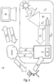
- Fig. 1 shows a first embodiment of a system 1 for calculating a set of optimized control parameters ⁇ or ⁇ k of a controller 3 or a controller 3 for an HVAC (heating, ventilation, air conditioning and refrigeration) system 2 with the characteristic signal flow according to the inventive method .
- the index k relates in each case to the current point in time and indicates that it is an iteratively optimized set of control parameters.
- the set of control parameters ⁇ without the running index k is used, for example, in the conventional least squares method without an iterative calculation method.
- a heating system 2 is considered below as an example of an HVAC system 2.
- the heating system 2 is installed in a building.
- an individual room 9 is considered as an example, the temperature T R of which is controlled by the heating system 2.
- This room 9 can also be used as a reference room for temperature control of the entire building. Alternatively, several reference rooms can be used, or temperature control can take place for each room in the building.
- the heating system 2 continuously records relevant system states such as the outside temperature T A , the room temperature T R , the flow temperature T VL , the return temperature T RL and the mass flow ⁇ of a carrier medium through a flow line or through a return line of the heating system 2 and transmits these measured values together as a data packet D k of the measurement time t k via the Internet to a server 8.
- the solar radiation G sol which contributes to the heating of the building or the room, can be recorded via a suitable sensor.
- the server 8 is designed to store and evaluate the received data packets D k , and thus to determine a set of optimized control parameters ⁇ k for a heating controller 3 of the heating system 2.
- the set of optimized control parameters ⁇ k can then be transmitted to a user B, for example to the heating engineer or the end customer. Then he has the possibility to decide to take over the control parameters ⁇ k .
- user B sets the control parameters ⁇ k on controller 3.
- the optimized control parameters ⁇ k can also be transmitted directly to the heating controller 3 via the Internet and taken over by the latter.
- the method according to the invention can thus also be used in heating regulators of older heating systems whose control parameters cannot be adjusted via the Internet.
- the central server 8 can also determine optimized control parameters of several different remote HVAC systems at the same time. For this purpose, the server 8 receives data packets from several HVAC systems, evaluates them and transmits the calculated, optimized control parameters to the respective user or controller.
- FIG. 2a a part of the system 1 for determining a set of optimized control parameters ⁇ k is shown.
- the system comprises several sensors for recording relevant system states.
- a flow temperature sensor 12 for detecting the flow temperature T VL arranged.
- a return temperature sensor 15 for detecting the return temperature T RL is arranged in the return of the heating system 2.
- a mass flow sensor for detecting the mass flow ⁇ can be arranged in the flow and / or return. in the room 9 arranged room temperature sensor 10 detects the room temperature T R.
- the heating system 2 supplies the flow with a carrier medium which transports heat to a heating element 16 arranged in the room 9.
- a desired room temperature T R , W can be specified via a thermostat 17 in room 9.
- an outside temperature sensor 11 for detecting the outside temperature T A and a solar radiation sensor 14 for detecting solar radiation G sol are arranged.
- at least one further sensor (not shown) for detecting an input of external heat source P FW can be arranged in the room.
- the source for an external heat source input P FW can be, for example, an electrical device that emits heat, such as a refrigerator or an electric stove.
- the controller 3 of the heating system 2 has a heating circuit controller 4 and a boiler controller 5. At least the recorded measured variables room temperature T R , outside temperature T A , target room temperature T R , W and flow temperature T VL are fed to the heating circuit controller 4. Optionally, at least one of the measured variables solar radiation G sol , mass flow ⁇ and / or external heat source input P FW can be fed to the heating circuit controller. On the basis of a control method specified for the heating controller 4, the heating controller 4 determines a target flow temperature T VL , W , which is output to a boiler controller 5. The control method used by the heating controller 4 can, for example, be based on a heating characteristic, as will be described in more detail below.
- Figure 2b illustrates the transmission of the measured values in the form of data packets D k to a server 8 for calculating optimized control parameters ⁇ k .
- the heating controller 3 comprises a device 22 for generating the data packet D k with the measured values and a point in time t k of the acquisition of the measured values. Via an interface 20 to the Internet, the data packet D k is transmitted to a server 8, which is also connected to the Internet via an interface 21.
- the server 8 comprises a buffer 6 in which the received data packet D k is initially temporarily stored, and a permanent memory 7 with a database in which the received data packets and calculated control parameters are stored.
- the server 8 also has a processor CPU which is configured to generate a set from the data packets to calculate the optimized control parameter ⁇ k.
- the set of optimized control parameters ⁇ k can then be transmitted again to the controller 4 or to a user of the heating system 2 via the interface 21.
- the heating controller 4 of the heating system 2 of the first exemplary embodiment can be regulated, for example, by means of a heating characteristic.
- the heating curve describes a relationship between the outside temperature T A and the setpoint of the flow temperature T VL , W of the heating system 2.
- a heating curve is characterized by the two parameters level ⁇ N and slope ⁇ S.
- Weather-compensated operation of the heating system 2 can be implemented with a heating characteristic.
- the system states flow temperature T VL , outside temperature T A and temperature in the reference room T R are determined using the corresponding in Fig. 2a temperature sensors 10, 11 and 12 shown.
- the target room temperature T R , W can be specified by a user, for example via the thermostat 17.
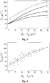
- Fig. 3 four exemplary heating characteristics a to d are shown for different values of the parameters inclination ⁇ S and level ⁇ N at a target room temperature T R , W of 20 ° C.
- the three heating curves a to c only differ in the parameter inclination ⁇ S. It can be seen that when the inclination ⁇ S increases (from a to c), the heating curve becomes steeper. A change in the parameter level ⁇ N shifts the characteristic in the vertical direction accordingly. This is shown as an example using the two heating curves c and d.
- the heating controller 4 uses the heating curve to calculate the set point of the flow temperature T VL, W, which as in Fig. 2a is passed on to the boiler controller 5.
- the two parameters slope and level of the heating characteristic can be set, for example, via a configuration menu on the heating controller.
- an installer of a heating system only sets the parameters when the heating system is commissioned, depending on the properties of the building.
- heating controllers are even operated with the parameters set in the delivery state.
- the parameters are usually only adjusted during ongoing heating operation if there is a significant deviation from the expected comfort of the heating system. To an undersupply with heat too avoid, heating systems are often operated with a higher flow temperature than necessary. This can lead to excessive energy consumption.
- the parameters inclination ⁇ S and level ⁇ N of the heating curve can be optimized with the system 1 according to the invention.
- the heating system 2 can thus be operated particularly efficiently. Excessive energy requirements or too little heat provided are avoided.
- the time-dependent measured values or setpoint values of the relevant state variables are recorded at regular time intervals and transmitted to the server 8 as data packets.
- the measured values can be displayed as data vectors that include all measured values of a time series.
- the measured values can be recorded over a period of one day with a resolution t S of 15 minutes, so that 96 data packets D 1 ... D 96 are generated and transmitted to the server in 24 hours.
- the server 8 can thus recalculate the optimized control parameters at regular time intervals t S.
- the control parameters can be calculated iteratively. This means that either the data packets from past times or previously calculated control parameters are used when calculating the control parameters.
- the advantage of the iterative approach is now illustrated by a comparison of a conventional method with the iterative calculation according to the invention.
- the calculation of the set of optimized control parameters can be done using known methods, for example. Two exemplary embodiments of the calculation method are described below.
- measurement data must first be recorded over a long period of time.
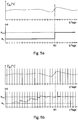
- the lower diagram of the Figure 5a shows an initial value ⁇ 0 of the control parameters as well as the desired set of optimal control parameters ⁇ opt .
- the conventional method here takes 60 days to deliver a result.
- the large number of data packets can also make the calculation of the control parameters very time-consuming.
- the advantage of the iterative execution of the calculation of optimized control parameters is shown on the basis of Figure 5b described.
- the upper diagram again shows a course of the room temperature T R over a period of 60 days.
- the lower diagram corresponds to the course of the control parameters based on the same initial value ⁇ 0 , as well as the set of optimal control parameters ⁇ opt .
- a daily calculation of the set of optimized control parameters is carried out, in each case with transmitted and stored 96 data packets, as well as on the basis of the set of control parameters calculated the day before. This means that a much smaller amount of data has to be processed in the calculation.
- the data packets can be deleted again every day after the calculation of the optimized control parameters, so that there is a much smaller memory requirement compared to the conventional method.
- the result iteratively approaches the desired optimal set of control parameters. This means that the controller is activated much earlier than in the comparative example of the Figure 5a can be operated with optimized control parameters.
- the cost of the calculation is much lower.
- a first exemplary embodiment of a calculation algorithm for calculating a set of optimized control parameters uses a least squares method.
- the matrices A and b represent the so-called data matrices of the underlying estimation problem. Typically, more data points and thus rows of the data matrices are available as parameters to be estimated, so that the present system of linear equations is overdetermined.
- Such a conventional least-squares method is for example in Stoer / Bulirsch: Numerical Mathematics 1, Springer Verlag, Berlin, 2007, p. 25 off described.
- a heating curve is characterized by a set with the two parameters slope ⁇ S and level ⁇ N.
- the standard least squares method can be generalized even further by weighting the individual rows of the data matrices and thus the data points.
- Ljung, L . System Identification - Theory for the User, Prentice Hall, Upper Saddle River (1999 ) and R. Isermann and M. Münchhof: Identification of Dynamic Systems, Springer (2010 ) described.
- the weighted least squares method later forms the theoretical starting point for the application of the least squares method to the optimization of the heating curve.
- the division is to be interpreted, for example, in such a way that variables with the index k -1 represent the results of optimized control parameters from previous data packets (data packets up to point in time k -1).
- the index k thus indicates a newly generated data packet D k , which is used to update new control parameters ⁇ k .
- Fig. 4 illustrates how a heating curve can be determined from the measured values.
- the measured values are plotted in a diagram.
- the plotted data points obtained from the measured values can also be filtered using a weighting function, so that only those data points are used for which the deviations e vL and / or e R are very small.
- the heating curve fitted to the data points then supplies the optimized control parameters ⁇ k , which can be transmitted to the heating controller 3.
- the setting parameters ⁇ VL and ⁇ R are essentially freely selectable. Depending on the amount of data packets available for the evaluation or depending on the scatter of the measured values, the setting parameters can be set larger or smaller in order to determine a set of optimized control parameters ⁇ k .
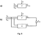
- the second exemplary embodiment deals with an explicit regulation of the temperature T R of a reference room 9 of a building.
- the second exemplary embodiment describes how a dynamic model M can be determined with the aid of the Internet and based on the stored data packets.
- Model M is a mathematical description of the relationships between the flow temperature T VL and the outside temperature T A on the room temperature T R. The model is determined based on the measured data.
- the data packets are generated and transmitted to a server 8 as described above with reference to the first exemplary embodiment. In the following, therefore, only the details of the mathematical method for calculating the optimized control parameters ⁇ k will be discussed.
- a mathematical building model enables the control parameters of a controller 3 of an HVAC system 2 to be optimized in a targeted manner, for example by means of a P, PI or PID controller, based on the model.
- the optimization can take place, for example, using standard control methods such as the root locus curve, frequency line method, etc.
- the parameters of the building model are determined and the optimized control parameters ⁇ k are calculated, as in the first exemplary embodiment, on a server 8 which communicates with the controller 3 via an Internet connection.
- the controller 3 itself works locally, for example in the heat generator of a heating system 2, and is automatically re-parameterized at regular intervals (for example daily, weekly or monthly).
- the control parameters are optimized using a model M of the controlled system.
- a calculation algorithm executed on the server 8 determines a mathematical relationship between the input and output data of the control process on the basis of the measurement data obtained, that is to say the data packets D k .
- FIG. 6a shows the initial situation with an exemplary process P, here a heating circuit.
- the outside temperature T A is a measurable disturbance variable.
- the flow temperature T VL of the heating circuit is the input variable.
- the room temperature T R is the output or controlled variable.
- the aim of the method is to determine a mathematical model M so that the output variable T ⁇ R supplied by the model M corresponds as precisely as possible to the measured room temperature T R corresponds to, as in Figure 6b shown schematically.
- the goal is therefore to minimize the deviation e between the output variable T ⁇ R and the measured room temperature T R.
- a time-discrete transfer function in the frequency range for the flow temperature G VL (Z) and a time-discrete transfer function for the outside temperature G A ( Z ) can be selected, from which T R.
- Z G VL Z ⁇ T VL Z + G A.
- the time-discrete transfer function in the frequency domain is expressed here as a time-discrete transfer function in the image area of a Z-transformation.
- N p is the number of poles of the transfer function and N Z, VL or N Z, A is the number of corresponding zeros. In principle, these can be freely selected, but can usually be determined in advance for physical reasons.
- the mathematical model M calculates the model output using historical values of the outside temperature T A and room temperature T R , which are stored as data packets in the storage medium 7 of the server 8.
- the matrices A and b can be generated from the data packets D i. If further disturbance variables are known, such as solar radiation G sol or an external heat source input P FW , the model can be expanded accordingly.
- the problem is converted into a least squares problem.
- the data packets D 1 to D N are used for this purpose.
- N 96 is assumed for one day.
- VL 1 N Z
- A. 1
- T R. k - a 1 T R. k - 1 - a 0 T R. k - 2 + b VL , 1 T VL k - 1 + b VL , 0 T VL k - 2 + b A. , 1 T A. k - 1 + b A. , 0 T A. k - 2
- T R. 1 ⁇ T R. N - a 1 T R. 0 - a 0 T R. - 1 + b VL , 1 T VL 0 + b VL , 0 T VL - 1 + b A. , 1 T A. 0 + b A. , 0 T A. - 1 ⁇ - a 1 T R. N - 1 - a 0 T R. N - 2 + b VL , 1 T VL N - 1 + b VL , 0 T VL N - 2 + b A. , 1 T A. N - 1 + b A. , 0 T A.
- the matrices A and b can therefore be generated from the data packets D i transmitted to the server 8.
- model M Since the parameters of model M are updated cyclically, for example daily, weekly or monthly, the result is an adaptive or optimized control of the heating system 2 that is adapted to the process (here a heating circuit) updated cyclically accordingly. A continuous, internet-based optimization of the controller 3 can thus take place.
- the advantage and innovation of the method is that there is no need to store and process the parameters on the embedded systems of the heat generator for the purpose of identifying the parameters, since these calculations are made on the corresponding capacities of the central platform on the Internet.
Description
Die vorliegende Erfindung betrifft ein Verfahren zum internetgestützten Optimieren von Regelparametern eines Reglers oder einer Steuerung für eine Heizungs-, Lüftungs-, Klima- und Kältetechnik- (HLKK-) Anlage, insbesondere eine Zentralheizung für ein Gebäude. Die Erfindung betrifft ferner ein System zum Ausführen des erfindungsgemäßen Verfahrens.The present invention relates to a method for internet-based optimization of control parameters of a regulator or a controller for a heating, ventilation, air conditioning and refrigeration (HVAC) system, in particular a central heating system for a building. The invention also relates to a system for carrying out the method according to the invention.
Typischerweise werden Regler oder Steuerungen von HLKK-Anlagen mit Steuerungs- und/oder Regelalgorithmen betrieben, deren Parametrierung durch einen Benutzer, zum Beispiel den Heizungsbauer oder den Endkunden, bei der Inbetriebnahme erfolgt. Eine nicht optimale Parametrierung, also eine Verwendung von nicht optimalen Regelparametern der Steuerungs- und/oder Regelalgorithmen, kann dazu führen, dass zu viel Energie verbraucht wird. Andererseits könnte beispielsweise bei niedrigen Außentemperaturen zu wenig thermische Leistung, zum Heizen eines Gebäudes bereitgestellt werden. Entsprechend ist denkbar, dass bei hohen Außentemperaturen zu wenig thermische Leistung zum Kühlen eines Gebäudes bereitgestellt werden könnte. In solchen Fällen kann der Benutzer der HLKK-Anlage die Regelparameter weiter (gegebenenfalls iterativ) an den jeweils betrachteten Anwendungsfall, zum Beispiel in Abhängigkeit der Gebäudedynamik, anpassen, um die Regelgüte zu erhöhen, Betriebskosten zu senken oder die Effizienz des Systems zu steigern. Um die Regelparameter zu optimieren, muss der Benutzer allerdings über Expertenwissen über den zu regelnden Prozess sowie über den Einfluss der Parameter der Algorithmen auf den Anlagenbetrieb verfügen. Alternativ zum manuellen Anpassen der Regelparameter von Steuerungs- und/oder. Regelalgorithmen kann eine automatische Anpassung durch ein überlagertes· Identifikations- und Adaptionsverfahren erfolgen. Heizungsbauer und Endkunden sind dann vollständig von der Aufgabe des Optimierens der Parametrierung befreit. Auf diese Weise können beispielsweise adaptive Heizkennlinien von Heizkreisen realisiert werden.Typically, regulators or controls of HVAC systems are operated with control and / or regulating algorithms, the parameters of which are set by a user, for example the heating engineer or the end customer, during commissioning. A non-optimal parameterization, i.e. the use of non-optimal control parameters of the control and / or regulation algorithms, can lead to too much energy being consumed. On the other hand, if the outside temperature is low, too little thermal power could be provided to heat a building. Accordingly, it is conceivable that too little thermal power could be provided for cooling a building at high outside temperatures. In such cases, the user of the HVAC system can further adapt the control parameters (if necessary iteratively) to the particular application under consideration, e.g. depending on the building dynamics, in order to increase the control quality, reduce operating costs or increase the efficiency of the system. In order to optimize the control parameters, however, the user must have expert knowledge of the process to be controlled and the influence of the parameters of the algorithms on the system operation. As an alternative to manually adjusting the control parameters of the control and / or. Control algorithms can be automatically adapted by means of a superimposed identification and adaptation process. Heating engineers and end customers are then completely freed from the task of optimizing the parameterization. In this way, for example, adaptive heating characteristics can be implemented for heating circuits.
Gemäß dem Stand der Technik kann eine witterungsgeführte, also in Abhängigkeit des Wetters oder der Jahreszeit betriebene, Heizungsregelung dafür sorgen, dass die Vorlauftemperatur des Heizkreises in Abhängigkeit der Außentemperatur auf den Wärmebedarf im Gebäude angepasst wird. Bei optimaler Einstellung der Heizungsanlage wird nur so viel Wärme erzeugt, wie aktuell benötigt wird. Dazu wird zum Beispiel die Außentemperatur gemessen und daraus, in Abhängigkeit einer gewünschten Raumtemperatur (Raumsolltemperatur) sowie anhand von Gebäuderandbedingungen, die benötigte Vorlauftemperatur zum Erreichen der Raumsolltemperatur ermittelt. Die Beziehung zwischen Außen- und Vorlauftemperatur wird beispielsweise durch eine Heizkennlinie beschrieben. Die Heizkennlinie bewirkt, dass bei einer niedrigeren Außentemperatur eine höhere Vorlauftemperatur eingestellt wird.According to the state of the art, a weather-compensated heating control, i.e. one operated as a function of the weather or the season, can ensure that the flow temperature of the heating circuit is adapted to the heat demand in the building as a function of the outside temperature. With the optimal setting of the heating system, only as much heat is generated as is currently required. For this purpose, the outside temperature is measured, for example, and the required flow temperature to achieve the desired room temperature is determined from this, depending on a desired room temperature (target room temperature) and on the basis of building boundary conditions. The relationship between outside and flow temperature is described, for example, by a heating curve. The heating curve means that a higher flow temperature is set when the outside temperature is lower.
Beispiele für eine Heizkennlinie sind in
Ein Einstellen der Heizkennlinie findet in der Regel nur selten, üblicherweise bei der Installation einer Heizungsanlage, und gegebenenfalls bei wiederholt zu geringer Raumtemperatur, statt. Hierdurch kann eine Heizungsanlage mit einem höheren als notwendigen Energieverbrauch betrieben werden. Die vorliegende Erfindung stellt ein Verfahren sowie ein entsprechendes System zum Optimieren von Regelparametern eines Reglers beziehungsweise einer Steuerung einer HLKK-Anlage, also insbesondere einer Heizungsanlage, über das Internet bereit. Durch das erfindungsgemäße Verfahren beziehungsweise System kann eine HLKK-Anlage auf sich ändernde Randbedingungen, die zum Beispiel durch Schwankungen der Außentemperatur, der Sonneneinstrahlung oder durch Veränderungen an oder im Gebäude selbst verursacht oder beeinflusst werden, angepasst werden. Somit kann eine HLKK-Anlage besonders effizient und energiesparend betrieben werden. Außerdem kann eine Unterversorgung vermieden werden.As a rule, the heating characteristic is only rarely set, usually when installing a heating system and, if necessary, when the room temperature is repeatedly too low. As a result, a heating system can be operated with a higher energy consumption than necessary. The present invention provides a method and a corresponding system for optimizing control parameters of a regulator or a control of an HVAC system, that is to say in particular of a heating system, via the Internet. With the method or system according to the invention, an HVAC system can be adapted to changing boundary conditions, which are caused or influenced, for example, by fluctuations in the outside temperature, solar radiation or changes on or in the building itself. This means that an HVAC system can be operated in a particularly efficient and energy-saving manner. In addition, an undersupply can be avoided.
Ein Verfahren zum internetgestützten Adaptieren einer Heizungsanlage wird zum Beispiel in der US Patentanmeldung Nr.
Ein weiteres Regelungssystem für die Heizung eines Gebäudes ist aus der deutschen Übersetzung
Das im Folgenden beschriebene erfindungsgemäße Verfahren soll die für das Regeln beziehungsweise Steuern einer in einem Gebäude installierten Heizungs-, Lüftungs-, Klima- und Kältetechnik- (HLKK-) Anlage erforderlichen Regelparameter internetgestützt optimieren. Die optimierten Parameter können dann entweder automatisch oder durch einen Benutzer am Regler oder an der Steuerung eingestellt werden. Dazu kann eine Handlungsempfehlung an den Benutzer des Reglers oder der Steuerung, wie zum Beispiel an einen Heizungsbauer oder einen Endkunden der Heizungsanlage gesendet werden. Das Anzeigen der optimierten Regelparameter kann über eine Vorrichtung, die über das Internet kommuniziert, erfolgen, beispielsweise durch eine App auf einem mobilen Endgerät.The method according to the invention described below is intended to optimize the control parameters required for regulating or controlling a heating, ventilation, air conditioning and refrigeration (HVAC) system installed in a building with the aid of the Internet. The optimized parameters can then be set either automatically or by a user on the controller or on the control. For this purpose, a recommendation for action can be sent to the user of the controller or the control system, for example to a heating contractor or an end customer of the heating system. The optimized control parameters can be displayed using a device that communicates via the Internet, for example using an app on a mobile device.
Zum Ermitteln und Optimieren der Regelparameter erfasst eine Vorrichtung (beispielsweise ein eingebettetes System) relevante Systemzustände der HLKK-Anlage über einen gewissen Zeitraum mit einer geeigneten Sensorik und sendet diese über eine Internetverbindung zur weiteren Verarbeitung an einen zentralen Server. Die relevanten Systemzustände umfassen zum Beispiel eine Außentemperatur des Gebäudes, eine Raumtemperatur eines Referenzraumes, eine Vorlauftemperatur, eine Rücklauftemperatur, eine vorgegebene Raumsolltemperatur, eine vorgegebene Vorlaufsolltemperatur, einen Grad der Sonneneinstrahlung auf das Gebäude und einen Fremdwärmequelleneintrag in den Referenzraum. Diese Systemzustände oder Systemgrößen werden teilweise als Messwerte von entsprechenden Sensoren erfasst und als Datenpakete an den Server übertragen.To determine and optimize the control parameters, a device (for example an embedded system) records relevant system states of the HVAC system over a certain period of time with suitable sensors and sends them to a central server via an Internet connection for further processing. The relevant system states include, for example, an outside temperature of the building, a room temperature of a reference room, a flow temperature, a return temperature, a specified set room temperature, a specified set flow temperature, a degree of solar radiation on the building and an input of external heat sources into the reference room. These system states or system variables are partially recorded as measured values by corresponding sensors and transmitted to the server as data packets.
Auf dem Server erfolgen Verarbeitung und Analyse der erfassten Systemgrößen zum Berechnen der optimierten Regelparameter. Außerdem überträgt der Server die durch einen Berechnungsalgorithmus optimierten Regelparameter an den Benutzer. Die Übergabe der Parameter an den Nutzer kann als eine Handlungsempfehlung zum Einstellen der optimierten Regelparameter im Regler der HLKK-Anlage ausgeführt sein. Alternativ können die berechneten optimierten Regelparameter auch vom Regler oder der Steuerung der HLKK-Anlage direkt empfangen und übernommen werden, so dass eine automatische Optimierung der Regelung der HLKK-Anlage erfolgen kann. Die Optimierung der Regelparameter kann in regelmäßigen Zeitintervallen erfolgen, so dass die HLKK-Anlage kontinuierlich an sich ändernde Randbedingungen angepasst werden kann.The server processes and analyzes the recorded system variables to calculate the optimized control parameters. In addition, the server transmits the control parameters, which have been optimized by a calculation algorithm, to the user. The transfer of the parameters to the user can be implemented as a recommendation for setting the optimized control parameters in the controller of the HVAC system. Alternatively, the calculated optimized control parameters can also be received and accepted directly by the controller or the control of the HVAC system, so that automatic optimization of the control of the HVAC system can be done. The control parameters can be optimized at regular time intervals so that the HVAC system can be continuously adapted to changing boundary conditions.
Der Erfindung liegt die Aufgabe zugrunde, ein gegenüber dem Stand der Technik verbessertes Verfahren zum Optimieren von Regelparameter eines Regler beziehungsweise einer Steuerung einer HLKK-Anlage anzugeben. Außerdem soll ein verbessertes System zum Optimieren von Regelparameter eines Regler beziehungsweise einer Steuerung einer HLKK-Anlage bereitgestellt werden.The invention is based on the object of specifying a method, which is improved over the prior art, for optimizing control parameters of a regulator or a control of an HVAC system. In addition, an improved system for optimizing control parameters of a regulator or a control of an HVAC system is to be provided.
Erfindungsgemäß wird die Aufgabe gelöst durch ein Verfahren zum Ermitteln eines Satzes optimierter Regelparameter eines Reglers oder einer Steuerung für eine HLKK- (Heizungs-, Lüftungs-, Klima-und Kältetechnik) Anlage gemäß Anspruch 1. Die Aufgabe wird ferner gelöst durch ein System zum Ermitteln eines Satzes optimierter Regelparameter eines Reglers oder einer Steuerung für eine HLKK-Anlage gemäß Anspruch 6. Das erfindungsgemäße System ist insbesondere konfiguriert, das erfindungsgemäße Verfahren zum Ermitteln eines Satzes optimierter Regelparameter auszuführen. Die HLKK-Anlage ist in einem Gebäude installiert und dazu konfiguriert, die Temperatur mindestens eines Raumes, vorzugsweise aller Räume des Gebäudes, zu regeln.According to the invention, the object is achieved by a method for determining a set of optimized control parameters of a regulator or a control for an HVAC (heating, ventilation, air conditioning and refrigeration) system according to
In einem ersten Schritt des Verfahrens wird mindestens eine Außentemperatur, also die Temperatur außerhalb des Gebäudes, erfasst. Zum Erfassen der Außentemperatur umfasst das System mindestens einen Außentemperatursensor. Dieser ist an einem dafür zweckdienlichen Punkt außerhalb des Gebäudes, zum Beispiel an einem windgeschützten Ort am Dach des Gebäudes, angeordnet.In a first step of the method, at least one outside temperature, that is to say the temperature outside the building, is recorded. To detect the outside temperature, the system comprises at least one outside temperature sensor. This is arranged at a convenient point outside the building, for example in a sheltered place on the roof of the building.
In einem weiteren Schritt wird mindestens eine Raumisttemperatur mindestens eines Referenzraumes, also die aktuelle Lufttemperatur des mindestens einen Raumes, dessen Temperatur für die Regelung der HLKK-Anlage herangezogen werden soll, erfasst. Zum Erfassen der Raumisttemperatur umfasst das System mindestens einen im Referenzraum angeordneten Raumtemperatursensor. Anstatt in nur einem Referenzraum die Raumisttemperatur zu messen, kann das Verfahren beziehungsweise das System auch derart erweitert werden, dass in mehreren oder sogar in allen Räumen des Gebäudes jeweils mindestens eine Raumisttemperatur gemessen wird. In diesem Fall umfasst das System eine Vielzahl von Raumtemperatursensoren.In a further step, at least one actual room temperature of at least one reference room, that is to say the current air temperature of the at least one room, the temperature of which is to be used for regulating the HVAC system, is recorded. To detect the actual room temperature, the system includes at least one room temperature sensor arranged in the reference room. Instead of measuring the actual room temperature in just one reference room, the method or the system can also be expanded in such a way that at least one actual room temperature is measured in several or even in all rooms of the building. In this case the system comprises a large number of room temperature sensors.
Ferner wird in einem Verfahrensschritt eine Vorlauftemperatur erfasst. Die Vorlauftemperatur ist die Temperatur eines wärme- beziehungsweise kälteübertragenden Trägermediums eines Heiz- oder Kühlkreises der HLKK-Anlage. Zum Erfassen der Vorlauftemperatur umfasst das System mindestens einen Vorlauftemperatursensor.Furthermore, a flow temperature is recorded in a method step. The flow temperature is the temperature of a heat or cold transferring medium of a heating or cooling circuit of the HVAC system. The system includes at least one flow temperature sensor to detect the flow temperature.
In einem weiteren Verfahrensschritt wird eine vorgegebene Raumsolltemperatur erfasst. Zum Vorgeben der Raumsolltemperatur umfasst das System eine Einrichtung zum Vorgeben einer Raumsolltemperatur. Die Raumsolltemperatur kann beispielsweise über einen im Raum angeordneten Thermostaten von einem Benutzer vorgegeben werden oder es kann eine Raumsolltemperatur über eine entsprechende Schnittstelle von einer übergeordneten elektronischen Einrichtung, wie zum Beispiel einer Gebäudesteuerung, empfangen werden.In a further process step, a specified target room temperature is recorded. For specifying the target room temperature, the system comprises a device for specifying a target room temperature. The target room temperature can for example be specified by a user via a thermostat arranged in the room, or a target room temperature can be received via a corresponding interface from a higher-level electronic device, such as a building control.
Ferner wird eine vorgegebene Vorlaufsolltemperatur erfasst. Hierzu umfasst das System eine Einrichtung zum Vorgeben einer Vorlaufsolltemperatur. Diese Einrichtung kann zum Beispiel Teil des Reglers oder der Steuerung der HLKK-Anlage sein. Die vorgegebene Vorlaufsolltemperatur kann beispielsweise anhand der gemessenen Außentemperatur und der vorgegebenen Raumsolltemperatur über eine Heizkennlinie (siehe
In einem weiteren Verfahrensschritt wird ein Datenpaket aus den erfassten Messwerten und einem Zeitpunkt des Erfassens erzeugt. Hierzu umfasst das System eine Einrichtung zum Erzeugen eines Datenpakets. Das Datenpaket kann eine Vielzahl von Messwerten enthalten, die für das Berechnen optimierter Regelparameter zweckdienlich sind. Darüber hinaus können die Datenpakete auch zum Überwachen des aktuellen Zustands oder einer historischen Zustands der HLKK-Anlage verwendet werden.In a further method step, a data packet is generated from the recorded measured values and a point in time when they were recorded. For this purpose, the system comprises a device for generating a data packet. The data packet can contain a large number of measured values which are useful for calculating optimized control parameters. In addition, the data packets can also be used to monitor the current status or a historical status of the HVAC system.
Die Schritte des Erfassens der Außentemperatur, Raumisttemperatur, Vorlauftemperatur, Raumsolltemperatur und Vorlaufsolltemperatur können im Wesentlichen gleichzeitig oder auch kurz nacheinander ausgeführt werden. Vorzugsweise werden die Messwerte zyklisch zu vorgegebenen Zeitpunkten erfasst. Für das Erzeugen des Datenpakets muss den Messwerten lediglich ein bestimmter Zeitpunkt zugeordnet werden. Dieser zugeordnete Zeitpunkt kann auch der Zeitpunkt des Erzeugens des Datenpaktes sein. Da Temperaturänderungen im Vergleich zu den Vorgängen des Erfassens und Verarbeitens der Messwerte jedoch relativ träge sind, haben kleine Zeitunterschiede keine große Auswirkung.The steps of recording the outside temperature, actual room temperature, flow temperature, target room temperature and target flow temperature can be carried out essentially simultaneously or in quick succession. The measured values are preferably recorded cyclically at predetermined times. To generate the data packet, the measured values only need to be assigned a specific point in time. This assigned point in time can also be the point in time at which the data packet was generated. However, since changes in temperature are relatively sluggish compared to the processes of acquiring and processing the measured values, small time differences have no great effect.
Das erzeugte Datenpaket wird über eine Internetverbindung an einen Server übertragen und in einem mit dem Server verbundenen Speichermedium gespeichert. Das Speichermedium kann zum Beispiel einen Pufferspeicher zum temporären Zwischenspeichern der Empfangenen Datenpakete und einen permanenten Speicher zum mit einer Datenbank zum langfristigen Speichern der Datenpakete umfassen. Zum Übertragen des Datenpakets umfasst das System eine mit dem Regler beziehungsweise der Steuerung der HLKK-Anlage verbundene Übertragungseinrichtung. Die Übertragungseinrichtung umfasst eine geeignete Schnittstelle zum Übertragen von Datenpaketen an den Server über das Internet. Entsprechend umfasst der Server eine geeignete Schnittstelle zum Empfangen der Datenpakte. Umgekehrt ist die Schnittstellen des Servers auch dazu geeignet Daten, insbesondere den Satz optimierter Regelparameter, an den Regler oder an einen Benutzer zu senden. Entsprechend ist die Schnittstelle des Reglers konfiguriert, Daten zu empfangen.The data packet generated is transmitted to a server via an Internet connection and stored in a storage medium connected to the server. The storage medium can comprise, for example, a buffer memory for temporarily storing the received data packets and a permanent memory with a database for long-term storage of the data packets. To transmit the data packet, the system includes a transmission device connected to the controller or the control of the HVAC system. The Transmission device comprises a suitable interface for transmitting data packets to the server via the Internet. The server accordingly comprises a suitable interface for receiving the data packets. Conversely, the interface of the server is also suitable for sending data, in particular the set of optimized control parameters, to the controller or to a user. The controller's interface is configured accordingly to receive data.
Anhand der Messwerte des übertragenen und gespeicherten Datenpakets wird ein Satz optimierter Regelparameter berechnet. Das Berechnen der Regelparameter erfolgt zudem anhand von Messwerten einer Vielzahl weiterer zu früheren Zeitpunkten eines festgelegten Zeitraums erzeugter Datenpakete und/oder mindestens eines einer Vielzahl zuvor ermittelter Sätze optimierter Regelparameter.A set of optimized control parameters is calculated based on the measured values of the transmitted and stored data packet. The control parameters are also calculated on the basis of measured values from a large number of further data packets generated at earlier times in a specified period and / or at least one of a large number of previously determined sets of optimized control parameters.
Die Verwendung von weiteren Messwerten beziehungsweise von weiteren Datenpaketen einer Vielzahl früherer Zeitpunkte oder mindestens eines zuvor ermittelten Satzes optimierter Regelparameter für das Berechnen des neuen Satzes optimierter Regelparameter ermöglicht ein iteratives Berechnen der Regelparameter. In anderen Worten ausgedrückt, kann der Algorithmus zum Berechnen der Regelparameter konfiguriert sein, dass bei jedem erneuten Durchführen zusätzliche Datenpakete verwendet werden. Es erfolgt also eine schrittweises Annähern an die optimalen Regelparameter beim Wiederholen des Berechnungsvorgangs. Die Bedeutung der Begriffe "optimierte Regelparameter" und "optimale Regelparameter" wird im Folgenden noch näher beschrieben.The use of further measured values or of further data packets from a large number of earlier times or at least one previously determined set of optimized control parameters for calculating the new set of optimized control parameters enables the control parameters to be calculated iteratively. In other words, the algorithm for calculating the control parameters can be configured so that additional data packets are used each time it is carried out again. There is therefore a step-by-step approach to the optimal control parameters when the calculation process is repeated. The meaning of the terms "optimized control parameters" and "optimal control parameters" is described in more detail below.
Das Berechnen des Satzes optimierter Regelparameter erfolgt durch Ausführen eines Berechnungsalgorithmus auf dem Server. Hierzu umfasst der Server mindestens einen Prozessor, der konfiguriert ist, den Algorithmus auszuführen.The set of optimized control parameters is calculated by executing a calculation algorithm on the server. For this purpose, the server comprises at least one processor that is configured to execute the algorithm.
Der berechnete Satz optimierter Regelparameter wird in dem mit dem Server verbundenen Speichermedium gespeichert und über die Internetverbindung vom Server an den Regler oder die Steuerung der HLKK-Anlage übertragen. Alternativ oder zusätzlich kann eine Benachrichtigung an einen Benutzer der HLKK-Anlage mit dem berechneten Satz optimierter Regelparameter gesendet werden. Die Schnittstellen des Servers und der Reglers oder der Steuerung der HLKK-Anlage sind somit jeweils zum Senden und Empfangen von Datenpaketen beziehungsweise Regelparametern ausgelegt.The calculated set of optimized control parameters is stored in the storage medium connected to the server and transferred from the server to the controller or the control of the HVAC system via the Internet connection. Alternatively or additionally, a notification can be sent to a user of the HVAC system with the calculated set of optimized control parameters. The interfaces of the server and the controller or the control of the HVAC system are thus each designed for sending and receiving data packets or control parameters.
Um das Ergebnis der Berechnung optimierter Regelparameter zu verbessern, können weitere Messwerte erfasst werden, die beim Berechnen der Regelparameter berücksichtigt werden. Dazu wird vorzugsweise mindestens eine Rücklauftemperatur, ein Massenstrom des Trägermediums durch den Vorlauf, eine auf das Gebäude einfallende Sonneneinstrahlung und/oder ein Fremdwärmequelleneintrag erfasst. Das Datenpaket wird dann entsprechend mit dem oder den weiteren Messwert(en) erzeugt. Der Berechnungsalgorithmus verwendet beim Berechnen des Satzes optimierter Regelparameter mindestens einen der weiteren zusätzlichen Messwerte.In order to improve the result of the calculation of optimized control parameters, further measured values can be recorded, which are taken into account when calculating the control parameters. For this purpose, at least one return temperature, a mass flow of the carrier medium through the flow, solar radiation incident on the building and / or a Entry of external heat sources recorded. The data packet is then generated accordingly with the further measured value (s). When calculating the set of optimized control parameters, the calculation algorithm uses at least one of the further additional measured values.
Zum Erfassen der Rücklauftemperatur kann das System mindestens einen Rücklauftemperatursensor aufweisen. Zum Erfassen des Massenstroms des Trägermediums durch den Vorlauf oder Rücklauf kann das System mindestens einen Massenstromsensor, der entsprechend im Vorlauf oder Rücklauf angeordnet sein kann, aufweisen. Zum Erfassen der Sonneneinstrahlung kann das System einen Sensor zum Messen einer totalen Wärmeeinstrahlung, zum Beispiel einen Globalstrahlungssensor zum Messen der Sonneneinstrahlung, aufweisen. Zum Erfassen des Fremdwärmequelleneintrags kann das System eine Einrichtung zum Ermitteln eines Fremdwärmequelleneintrags aufweisen. Die Einrichtung zum Erzeugen eines Datenpakets kann entsprechend konfiguriert sein, das Datenpaket einschließlich des oder der weiteren Messwerte(s) zu erzeugen.To detect the return temperature, the system can have at least one return temperature sensor. To detect the mass flow of the carrier medium through the flow or return, the system can have at least one mass flow sensor, which can be arranged accordingly in the flow or return. To detect solar radiation, the system can have a sensor for measuring total heat radiation, for example a global radiation sensor for measuring solar radiation. In order to detect the entry of external heat sources, the system can have a device for determining an entry of external heat sources. The device for generating a data packet can be configured accordingly to generate the data packet including the further measured value (s).
Sonneneinstrahlung kann die Temperatur in einem Gebäude, zum Beispiel eines Raumes, stark beeinflussen. Da Sonneneinstrahlung Wetter- und Jahreszeitenschwankungen unterliegt, kann es vorteilhaft sein, wenn die Sonneneinstrahlung gemessen und beim Berechnen der Regelparameter berücksichtigt wird.Solar radiation can have a strong influence on the temperature in a building, for example a room. Since solar radiation is subject to weather and season fluctuations, it can be advantageous if the solar radiation is measured and taken into account when calculating the control parameters.
Ein Fremdwärmequelleneintrag kann von einer oder mehreren im Raum befindlichen Vorrichtung(en) stammen. Insbesondere könne elektrische Vorrichtungen Wärme abgeben. So können beispielsweise ein Kühlschrank oder ein Herd einen nicht unerheblichen Wärmeeintrag im Raum erzeugen.An input of external heat sources can originate from one or more device (s) located in the room. In particular, electrical devices can give off heat. For example, a refrigerator or stove can generate a not inconsiderable amount of heat in the room.
Der beim Berechnen des Satzes optimierter Regelparameter verwendete Zeitraum wird vorzugsweise in Abhängigkeit der Anzahl im Speichermedium gespeicherter Datenpakete vorgegeben. Je mehr gespeicherte Datenpakete im Speichermedium des Servers vorliegen, desto größer kann der festgelegte Zeitraum vorgegeben werden. Je größer der verwendete Zeitraum ist, desto genauer kann beispielsweise ein mathematisches Modell des zu regelnden Gebäudes berechnet werden. Eine lange Zeitreihe von gespeicherten Datenpaketen erlaubt es, die Regelstrecke genauer zu modellieren. Somit kann die Berechnung der optimierten Regelparameter verbessert werden.The time period used when calculating the set of optimized control parameters is preferably specified as a function of the number of data packets stored in the storage medium. The more stored data packets there are in the storage medium of the server, the longer the specified period can be specified. The longer the period of time used, the more precisely a mathematical model of the building to be controlled can be calculated, for example. A long time series of stored data packets allows the controlled system to be modeled more precisely. The calculation of the optimized control parameters can thus be improved.
Bei einer bevorzugten Ausführungsform des erfindungsgemäßen Verfahrens beziehungsweise des erfindungsgemäßen Systems umfasst das Berechnen des Satzes optimierter Regelparameter ferner einen Schritt des Ermittelns einer ersten Abweichung zwischen der Raumisttemperatur und der Raumsolltemperatur für jedes Datenpaket eines vorgegebenen Zeitraums. Eine kleine Abweichung bedeutet, dass die Regelung der HLKK-Anlage bereits gut funktioniert, also dass die zugehörigen Regelparameter bereits nahe an der optimalen Einstellung lagen. Je kleiner die Abweichung, desto näher sind die ermittelten Regelparameter an der optimalen Einstellung. Entsprechend kann in einem weiteren Schritt eine zweite Abweichung zwischen der Vorlauftemperatur und der vorgegebenen Vorlauftemperatur für jedes Datenpaket des vorgegebenen Zeitraums ermittelt werden.In a preferred embodiment of the method according to the invention or the system according to the invention, the calculation of the set of optimized control parameters further comprises a step of determining a first deviation between the actual room temperature and the target room temperature for each data packet of a predetermined period of time. A small Deviation means that the control of the HVAC system is already working well, i.e. that the associated control parameters were already close to the optimal setting. The smaller the deviation, the closer the determined control parameters are to the optimal setting. Correspondingly, in a further step, a second deviation between the flow temperature and the specified flow temperature can be determined for each data packet of the specified period.
In Abhängigkeit der ermittelten ersten und/oder zweiten Abweichung kann ein Gewichtungsfaktor zwischen 0 und 1 bestimmt werden. Der Gewichtungsfaktor beim Berechnen des Satzes optimierter Regelparameter hat den Zweck, dass Datenpakete mit niedriger erster und/oder zweiter Abweichung stärker berücksichtigt werden und Datenpakete mit hoher erster und/oder zweiter Abweichung weniger stark berücksichtig werden. In anderen Worten ausgedrückt, sucht der Algorithmus nach Datensätzen, bei denen Eingangsgrößen, wie zum Beispiel eine Vorlauftemperatur, erzeugt wurden, die zu einem nahezu optimalen Ausgangsverlauf, also zum Beispiel zu einer niedrigen Abweichung zwischen Raumtemperatur und Raumsolltemperatur, geführt haben.Depending on the determined first and / or second deviation, a weighting factor between 0 and 1 can be determined. The weighting factor when calculating the set of optimized control parameters has the purpose that data packets with a low first and / or second deviation are taken into account to a greater extent and data packets with a high first and / or second deviation are taken less into account. In other words, the algorithm searches for data sets in which input variables, such as a flow temperature, have been generated that have led to an almost optimal output curve, i.e., for example, to a low deviation between room temperature and target room temperature.
Alternativ kann der Satz optimierter Regelparameter nur aus solchen gespeicherten Datenpaketen, für welche die ermittelte erste Abweichung und/oder die ermittelte zweite Abweichung kleiner als oder gleich groß wie ein jeweils vorgegebener Schwellenwert sind/ist, berechnet werden. Dies entspricht dem Verwenden einer Gewichtungsfunktion, die entweder den Wert Null oder Eins annimmt.Alternatively, the set of optimized control parameters can only be calculated from those stored data packets for which the ascertained first deviation and / or the ascertained second deviation are / is smaller than or equal to a respectively predetermined threshold value. This is equivalent to using a weighting function that takes either the value zero or one.
Vorzugsweise erfolgt das Erfassen der Messwerte durch die jeweiligen Sensoren regelmäßig nach Ablauf eines vorgegebenen Zeitintervalls. Das Zeitintervall kann beispielsweise einige Minuten oder Stunden betragen. So kann zum Beispiel alle zehn oder fünfzehn Minuten ein Satz Messwerte erfasst und ein entsprechendes Datenpaket erzeugt werden. Ferner kann das Berechnen des Satzes optimierter Regelparameter durch den Prozessor wiederkehrend jeweils dann ausgeführt werden, wenn eine vorbestimmte Vielzahl vorgegebener Zeitintervalle abgelaufen ist, so dass eine entsprechende Vielzahl erzeugter Datenpakte zum Berechnen des Satzes optimierter Regelparameter im Speichermedium des Servers gespeichert vorliegt. Dies kann beispielsweise einmal, zweimal oder mehrmals am Tag, alle zwei Tage, einmal pro Woche oder nur wenige male pro Monat erfolgen. Die Zeitintervalle des Erfassens der Messwerte beziehungsweise des Berechnens der optimierten Regelparameter kann je nach verfügbaren Speicherplatz im Regler beziehungsweise beim Server eingestellt werden. Ferner können die Zeitintervalle auf die Komplexität der HLKK-Anlage, die Anzahl der Messwerte, die Geschwindigkeit der Internetverbindung oder ähnliche Randbedingungen angepasst werden.The measurement values are preferably recorded by the respective sensors regularly after a predetermined time interval has elapsed. The time interval can be a few minutes or hours, for example. For example, a set of measured values can be recorded every ten or fifteen minutes and a corresponding data package generated. Furthermore, the processor can recurrently calculate the set of optimized control parameters when a predetermined number of predetermined time intervals have expired, so that a corresponding number of generated data packets for calculating the set of optimized control parameters are stored in the storage medium of the server. This can be done, for example, once, twice or several times a day, every two days, once a week or only a few times a month. The time intervals for recording the measured values or calculating the optimized control parameters can be set depending on the available storage space in the controller or on the server. Furthermore, the time intervals can be adapted to the complexity of the HVAC system, the number of measured values, the speed of the Internet connection or similar boundary conditions.
Weitere vorteilhafte Ausgestaltungen werden nachfolgend anhand eines in den Zeichnungen dargestellten Ausführungsbeispiels, auf welches die Erfindung jedoch nicht beschränkt ist, näher beschrieben.Further advantageous configurations are described in more detail below with reference to an exemplary embodiment shown in the drawings, to which the invention is not limited, however.
Es zeigen schematisch:
-
Figur 1 Fig. 1 -
Figur 2 Fig. 2a und Fig. 2b -
Figur 3 Fig. 3 -
Figur 4 Fig. 4 -
Figur 5 Fig. 5a und Fig. 5b -
Figur 6 Fig. 6aFig. 6b illustriert die Approximation des Prozesses durch ein mathematisches Modell.
-
Figure 1 Figure 1 shows a structural set-up of a system or a method for internet-supported optimization of control parameters of a heating system according to a first exemplary embodiment of the invention. -
Figure 2, 2a and 2b show further details of the first embodiment of the invention. -
Figure 3 Figure 3 shows four exemplary heating characteristics. -
Figure 4 Figure 4 shows an example of a heating curve fitted to a large number of measured values. -
Figure 5, Figure 5a and Figure 5b each show a long time series of measured values of a room temperature and a corresponding course of optimized control parameters. -
Figure 6 Figure 6a illustrates a simplified signal flow of the physical process of a heating circuit.Figure 6b illustrates the approximation of the process using a mathematical model.
Bei der nachfolgenden Beschreibung einer bevorzugten Ausführungsform der vorliegenden Erfindung bezeichnen gleiche Bezugszeichen gleiche oder vergleichbare Komponenten.In the following description of a preferred embodiment of the present invention, the same reference symbols designate the same or comparable components.
Als Beispiel für eine HLKK-Anlage 2 wird im Folgenden eine Heizungsanlage 2 betrachtet. Die Heizungsanlage 2 ist in einem Gebäude installiert. Im Folgenden wird beispielhaft ein einzelner Raum 9 betrachtet, dessen Temperatur TR durch die Heizungsanlage 2 geregelt wird. Dieser Raum 9 kann auch als Referenzraum für die Temperaturregelung des gesamten Gebäudes verwendet werden. Alternativ können mehrere Referenzräume verwendet werden, beziehungsweise kann eine Temperaturregelung für jeden Raum des Gebäudes stattfinden.A
Die Heizungsanlage 2 erfasst fortlaufend relevante Systemzustände wie zum Beispiel die Außentemperatur TA, die Raumtemperatur TR , die Vorlauftemperatur TVL, die Rücklauftemperatur TRL und den Massenstrom ṁ eines Trägermediums durch eine Vorlaufleitung beziehungsweise durch eine Rücklaufleitung der Heizungsanlage 2 und überträgt diese Messwerte zusammengefasst als Datenpaket Dk des Messzeitpunkts tk über das Internet an einen Server 8. Zusätzlich kann über einen geeigneten Sensor die Sonneneinstrahlung Gsol die zur Erwärmung des Gebäudes beziehungsweise des Raumes beiträgt, erfasst werden.The
Der Server 8 ist dazu ausgelegt, die empfangenen Datenpakete Dk zu speichern und auszuwerten, und somit einen Satz optimierter Regelparameter Θ k für einen Heizungsregler 3 der Heizungsanlage 2 zu bestimmen. Der Satz optimierter Regelparameter Θ k kann anschließend an einen Benutzer B, zum Beispiel an den Heizungsbauer oder den Endkunden, übertragen werden. Dann hat dieser die Möglichkeit, sich zur Übernahme der Regelparameter Θ k zu entscheiden. In diesem Fall stellt der Benutzer B die Regelparameter Θ k am Regler 3 ein. Alternativ können die optimierten Regelparameter Θ k auch direkt über das Internet an den Heizungsregler 3 übertragen und von diesem übernommen werden.The
Das erfindungsgemäße Verfahren kann somit auch bei Heizungsreglern älterer Heizungssysteme eingesetzt werden, deren Regelparameter nicht über das Internet verstellt werden können. Der zentrale Server 8 kann außerdem zeitgleich optimierte Regelparameter mehrerer verschiedener entfernter HLKK-Anlagen bestimmen. Dazu empfängt der Server 8 Datenpakete mehrerer HLKK-Analgen, wertet diese aus und überträgt die errechneten optimierten Regelparameter an die jeweiligen Benutzer oder Regler.The method according to the invention can thus also be used in heating regulators of older heating systems whose control parameters cannot be adjusted via the Internet. The
Außerhalb des Gebäudes sind ein Außentemperatursensor 11 zum Erfassen der Außentemperatur TA und ein Sonnenstrahlsensor 14 zum Erfassen einer Sonneneinstrahlung Gsol angeordnet. Zusätzlich kann in dem Raum mindestens ein weiterer (nicht dargestellter) Sensor zum Erfassen eines Fremdwärmequelleneintrags PFW angeordnet sein. Quelle für einen Fremdwärmequelleneintrags PFW kann beispielsweise ein elektrisches Gerät sein, das Wärme abgibt, wie zum Beispiel ein Kühlschrank oder ein Elektroherd.Outside the building, an
Der Regler 3 der Heizungsanlage 2 weist einen Heizkreisregler 4 und einen Kesselregler 5 auf. Dem Heizkreisregler 4 werden mindestens die erfassten Messgrößen Raumtemperatur TR , Außentemperatur TA , Raumsolltemperatur T R,W und Vorlauftemperatur TVL zugeführt. Optional kann dem Heizkreisregler mindestens eine der Messgrößen Sonneneinstrahlung Gsol , Massenstrom ṁ und/oder Fremdwärmequelleneintrag PFW zugeführt werden. Anhand eines dem Heizregler 4 vorgegebenen Regelverfahren ermittelt der Heizregler 4 eine Vorlaufsolltemperatur TVL,W, die an einen Kesselregler 5 ausgegeben wird. Das vom Heizregler 4 verwendete Regelverfahren kann beispielsweise auf einer Heizkennlinie beruhen, wie im Folgenden näher beschrieben wird. Im Allgemeinen verwendet der Heizregler 4 einen Satz Regelparameter Θ = {ν 1 ... νN }. Bei einer Heizkennlinie umfasst der Satz Regelparameter beispielsweise die beiden Parameter Neigung ϑ1 = θ S und Niveau ϑ2 = θ L .The
Der Server 8 umfasst einen Puffer 6, in dem das empfangene Datenpaket D k zunächst zwischengespeichert wird, und einen permanenten Speicher 7 mit einer Datenbank, in der empfangene Datenpakete und berechnete Regelparameter gespeichert werden. Der Server 8 weist außerdem einen Prozessor CPU auf, der dazu konfiguriert ist, aus den Datenpaketen einen Satz optimierter Regelparameter Θ k zu berechnen. Der Satz optimierter Regelparameter Θ k kann dann über die Schnittstelle 21 wieder an den Regler 4 oder an einen Benutzer der Heizungsanlage 2 übertragen werden.The
Der Heizregler 4 der Heizungsanlage 2 des ersten Ausführungsbeispiels kann beispielsweise mittels einer Heizkennlinie geregelt werden. Die Heizkennlinie beschreibt einen Zusammenhang zwischen der Außentemperatur TA und dem Sollwert der Vorlauftemperatur TVL,W der Heizungsanlage 2. Eine Heizungskennlinie wird durch die beiden Parameter Niveau θN und Neigung θS charakterisiert. Der zu optimierende Satz Parameter Θ k der Heizkennlinie ist also Θ k = {θ N, θS } k· The
Mit einer Heizungskennlinie lässt sich ein witterungsgeführter Betrieb der Heizungsanlage 2 realisieren. Bei dem erfindungsgemäßen Optimierungsverfahren werden die Systemzustände Vorlauftemperatur TVL , Außentemperatur TA und Temperatur im Referenzraum TR mittels der entsprechenden in
In
Bei gattungsgemäßen Heizungsreglern gemäß dem Stand der Technik lassen sich die beiden Parameter Neigung und Niveau der Heizkennlinie zum Beispiel über ein Konfigurationsmenü am Heizungsregler einstellen. Häufig nimmt ein Installateur einer Heizungsanlage nur bei der Inbetriebnahme der Heizungsanlage eine Einstellung der Parameter in Abhängigkeit von Gebäudeeigenschaften vor. Teilweise werden Heizungsregler sogar mit den im Auslieferungszustand eingestellten Parametern betrieben. Eine Anpassung der Parameter im laufenden Heizbetrieb findet meist nur dann statt, wenn eine erhebliche Abweichung vom erwarteten Komfort der Heizungsanlage vorliegt. Um eine Unterversorgung mit Wärme zu vermeiden, werden Heizungsanlagen auch oft mit einer höheren Vorlauftemperatur als nötig betrieben. Es kann also zu einem überhöhten Energieverbrauch kommen.In the case of heating controllers of the generic type according to the prior art, the two parameters slope and level of the heating characteristic can be set, for example, via a configuration menu on the heating controller. Often times, an installer of a heating system only sets the parameters when the heating system is commissioned, depending on the properties of the building. In some cases, heating controllers are even operated with the parameters set in the delivery state. The parameters are usually only adjusted during ongoing heating operation if there is a significant deviation from the expected comfort of the heating system. To an undersupply with heat too avoid, heating systems are often operated with a higher flow temperature than necessary. This can lead to excessive energy consumption.
Die Parameter Neigung θS und Niveau θN der Heizkennlinie können mit dem erfindungsgemäßen System 1 optimiert werden. Somit kann die Heizungsanlage 2 besonders effizient betrieben werden. Ein überhöhter Energiebedarf oder eine zu geringe bereitgestellte Wärmemenge werden vermieden.The parameters inclination θ S and level θ N of the heating curve can be optimized with the
Wie zuvor beschrieben werden die zeitabhängigen Messwerte beziehungsweise Sollwerte der relevanten Zustandsgrößen in regelmäßigen Zeitabständen erfasst und als Datenpakete an den Server 8 übertragen. Die Messwerte können hierbei als Datenvektoren dargestellt werden, die alle Messwerte einer Zeitreihe umfassen. Beispielsweise können die Messwerte über den Zeitraum von einem Tag mit einer Auflösung tS von 15 Minuten aufgenommen werden, so dass in 24 Stunden 96 Datenpakete D 1 ... D 96 erzeugt und an den Server übertragen. Der Datenvektor ![]()
![]()
Der Vorteil des iterativen Ansatzes wird nun durch einen Vergleich eines herkömmlichen Verfahrens mit der erfindungsgemäßen iterativen Berechnung illustriert. Die Berechnung des Satzes optimierter Regelparameter kann zum Beispiel unter Verwendung bekannter Methoden erfolgen. Im Folgenden werden zwei Ausführungsbeispiele des Berechnungsverfahrens beschrieben. Bei einem herkömmlichen Least-Squares-Verfahren zum Optimieren von Regelparametern eines Heizungsreglers müssen zunächst Messdaten über einen langen Zeitraum aufgenommen werden. Das obere Diagramm der
Der Vorteil der iterativen Ausführung der Berechnung optimierter Regelparameter wird anhand von
Ein erstes Ausführungsbeispiel für einen Berechnungsalgorithmus zum Berechnen eines Satzes optimierter Regelparameter verwendet ein Least-Squares-Verfahren. Bei einem herkömmlichen Least-Squares-Verfahren werden optimierte Regelparameter Θ ermittelt, indem das lineare Gleichungssystem: ![]()
![]()
![]()
![]()
Aus Gleichung (1) folgt zunächst ![]()
![]()
Unter der Annahme, dass ATA regulär ist, folgen die zu schätzenden Parameter aus ![]()
![]()
![]()
![]()
Eine Heizkennlinie wird wie oben beschrieben durch einen Satz mit den zwei Parametern Neigung θS und Niveau ΘN charakterisiert. Die Anzahl der Parameter ist also q = 2. Damit ergibt sich: ![]()
![]()
Mit den Abkürzungen ![]()
![]()
![]()
![]()
![]()
![]()
Das Standard-Least-Squares-Verfahren lässt sich noch weiter verallgemeinern, indem eine Gewichtung der einzelnen Zeilen der Datenmatrizen und damit der Datenpunkte vorgenommen wird. Eine detaillierte wissenschaftliche Abhandlung der in diesem und nächsten Abschnitt beschriebenen Verfahren wird beispielsweise in
Das gewichtete Least-Squares-Verfahren bildet später den theoretischen Ausgangspunkt für die Anwendung des Least-Squares Verfahrens auf die Optimierung der Heizkennlinie. Die Gewichtungs-Matrix lässt sich wie folgt darstellen 
![]()
![]()
Zu lösen ist dann das gewichtete Least-Squares Problem: ![]()
![]()
Aus Gleichung (1) folgt dann unter der Annahme, dass ATWA regulär ist die Lösung zu ![]()
![]()
![]()
![]()
![]()
![]()
![]()
![]()
Bei den beiden zuvor dargestellten Ansätzen erweist sich als nachteilig, dass zuerst alle Datenpunkte und damit die Datenmatrizen A und b über den kompletten Zeitraum, beispielsweise einer Messung der Datenpakete D0 bis D N , wobei das Datenpaket D N das Ende des Messzeitraums festlegt, bestimmt werden müssen, was einen hohen Rechenaufwand erfordern kann. Für die großen Datenmengen müssen viel Speicherplatz sowie eine große Rechnerleistung bereitgestellt werden. Demgegenüber ist es daher vorteilhaft, bereits während der Messung, das heißt bei Vorliegen eines neuen Datenpakets, einen Satz optimierter Regelparameter zu bestimmen. Der hierfür benötigte Speicherplatz sowie die erforderliche Rechenleistung können wesentlich geringer ausfallen. Dies wird durch eine iterative Formulierung des Least-Squares Problems ermöglicht.In the two approaches presented above, it turns out to be disadvantageous that first all data points and thus the data matrices A and b over the entire period, for example a measurement of the data packets D 0 to D N , the data packet D N defining the end of the measurement period must be, which can require a high computing effort. A lot of storage space and a lot of computing power must be made available for the large amounts of data. In contrast, it is advantageous to determine a set of optimized control parameters already during the measurement, that is to say when a new data packet is available. The storage space required for this and the required computing power can be significantly lower. This is made possible by an iterative formulation of the least squares problem.
Für den iterativen Ansatz werden die Matrizen wie folgt dargestellt: ![]()
![]()
Dabei ist die Aufteilung beispielsweise so zu interpretieren, dass Variablen mit dem Index k - 1 Ergebnisse optimierter Regelparameter aus zurückliegenden Datenpaketen (Datenpakete bis zum Zeitpunkt k - 1) darstellen. Der Index k deutet somit auf ein neu erzeugtes Datenpaket D k hin, welches zur Aktualisierung neuer Regelparameter Θ k heran gezogen wird.The division is to be interpreted, for example, in such a way that variables with the index k -1 represent the results of optimized control parameters from previous data packets (data packets up to point in time k -1). The index k thus indicates a newly generated data packet D k , which is used to update new control parameters Θ k .
Aus Gleichung Fehler! Verweisquelle konnte nicht gefunden werden. folgt somit: 
Mit den Abkürzungen ![]()
![]()
![]()
![]()
![]()
![]()
Der Ablauf eines Verfahrens zum Berechnen von Θ k kann folgendermaßen am Beispiel der Datenpakete D 0 bis D N zusammengefasst werden.
- 1. Für das Datenpaket D 0 werden in einem ersten Schritt L 0 := A0 TW0A0 und r0 := A0 TW0b0 berechnet. Daraus lässt sich

- 2. In einem zweiten Schritt werden für das Datenpaket D1 L 1 := A 1 T W 1 A 1 und r 1 := A 1 TW 1 b 1 berechnet und daraus

- 3. Entsprechend werden in einem dritten Schritt für das Datenpaket D k Lk := Ak TWkAk und rk := Ak TWkbk berechnet. Hieraus kann

- 4. Anschließend wird L k-1 → L k-1 + Lk und r k-1 → r k-1 + rk gesetzt und die Laufvariable k um eins erhöht.
- 5. Wenn k = N + 1 wird, so wird das Verfahren beendet. Ansonsten kehrt man zurück zum
Schritt 3.
- 1. In a first step, L 0 : = A 0 T W 0 A 0 and r 0 : = A 0 T W 0 b 0 are calculated for the data packet D 0. From this you can
- 2. In a second step, for the data packet D 1 L 1 : = A 1 T W 1 A 1 and r 1 : = A 1 T W 1 b 1 are calculated and from this
- 3. Correspondingly, in a third step, D k L k : = A k T W k A k and r k : = A k T W k b k are calculated for the data packet. From this can
- 4. Then L k- 1 → L k- 1 + L k and r k -1 → r k- 1 + r k are set and the running variable k is increased by one.
- 5. When k = N + 1, the process is ended. Otherwise you return to step 3.
Für das Beispiel der Heizkennlinienoptimierung folgt: ![]()
![]()
![]()
![]()
![]()
![]()
![]()
![]()
![]()
![]()
Bei einer täglichen Berechnung mit einer Zeitauflösung von 15 Minuten sind die Parameter N = 96; q = 2. Im Speichermedium 7 des Servers 8 müssen nur die Parameter Θ k, L k-1 ,r k-1 gespeichert werden, so dass im Vergleich mit einem herkömmlichen Verfahren deutlich weniger Speicherbedarf besteht. Grundsätzlich können mit dem beschriebenen erfindungsgemäßen Verfahren alle Parameteroptimierungsprobleme einer Regelung, die sich durch Gleichung (1) darstellen lassen, effizient auf dem Server 8 verwaltet und berechnet werden.With a daily calculation with a time resolution of 15 minutes, the parameters are N = 96; q = 2. Only the parameters Θ k , L k − 1 , r k −1 need to be stored in the
Im Folgenden wird gezeigt, wie sich das zuvor beschriebene Verfahren bei der Optimierung einer Heizkennlinie anwenden lässt. Eine Heizkennlinie beschreibt einen statischen Zusammenhang zwischen Außentemperatur TA , Raumsolltemperatur T R,W und Vorlaufsolltemperatur TVL,W und wird beschrieben durch Gleichung (3): 
Aus Gleichungen (1) und (3) ergeben sich die Datenmatrizen: 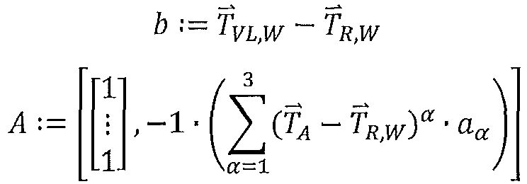
![]()
![]()
![]()
![]()
![]()
![]()
Mit den in
Als Gewichtungsfunktion kann zum Beispiel eine Gauss'sche Verteilungskurve verwendet werden: ![]()
![]()
Die Einstellparameter σVL und σ R sind im Wesentlichen frei wählbar. Je nach Menge der für die Auswertung verfügbaren Datenpakete beziehungsweise in Abhängigkeit der Streuung der Messwerte, können die Einstellparameter größer oder kleiner eingestellt werden, um einen Satz optimierter Regelparameter Θ k zu ermitteln.The setting parameters σ VL and σ R are essentially freely selectable. Depending on the amount of data packets available for the evaluation or depending on the scatter of the measured values, the setting parameters can be set larger or smaller in order to determine a set of optimized control parameters Θ k .
In Abgrenzung zur Heizkennlinie des ersten Ausführungsbeispiels behandelt das zweite Ausführungsbeispiel eine explizite Regelung der Temperatur TR eines Referenzraums 9 eines Gebäudes. Das zweite Ausführungsbeispiel beschreibt, wie internetgestützt und ausgehend von den gespeicherten Datenpaketen, ein dynamisches Modell M bestimmt werden kann. Das Modell M ist eine mathematische Beschreibung der Zusammenhänge zwischen der Vorlauftemperatur TVL und der Außentemperatur TA auf die Raumtemperatur TR. Das Modell wird auf Grundlage der gemessenen Daten bestimmt.In contrast to the heating characteristic of the first exemplary embodiment, the second exemplary embodiment deals with an explicit regulation of the temperature T R of a
Das Erzeugen und Übertragen der Datenpakete an einen Server 8 erfolgt wie schon zuvor anhand des ersten Ausführungsbeispiels beschrieben. Im Folgenden wird daher nur auf die Details der mathematischen Methode zum Berechnen der optimierten Regelparameter Θ k eingegangen.The data packets are generated and transmitted to a
Ein mathematisches Gebäudemodell ermöglicht ein gezieltes Optimieren der Regelparameter eines Reglers 3 einer HLKK-Anlage 2, zum Beispiel mittels eines P-, PI- oder PID-Reglers, auf Grundlage des Modells. Die Optimierung kann beispielsweise durch regelungstechnische Standardverfahren wie Wurzelortskurve, Frequenzlinienverfahren, etc. erfolgen. Das Bestimmen der Parameter des Gebäudemodells und das Berechnen der optimierten Regelparameter Θ k erfolgt wie im ersten Ausführungsbeispiel auf einem Server 8, der über eine Internetverbindung mit dem Regler 3 kommuniziert. Der Regler 3 selbst arbeitet lokal, zum Beispiel im Wärmeerzeuger eines Heizungssystems 2, und wird in regelmäßigen Abständen (z.B. täglich, wöchentlich oder monatlich) automatisiert neu parametriert.A mathematical building model enables the control parameters of a
Gemäß dem zweiten Ausführungsbeispiel der Erfindung werden die Regelparameter anhand eines Modells M der Regelstrecke optimiert. Dazu bestimmt ein auf dem Server 8 ausgeführter Berechnungsalgorithmus einen mathematischen Zusammenhang zwischen den Eingangs- und Ausgangsdaten des Regelprozesses anhand der gewonnenen Messdaten, also den Datenpaketen Dk .According to the second exemplary embodiment of the invention, the control parameters are optimized using a model M of the controlled system. For this purpose, a calculation algorithm executed on the
Ziel des Verfahrens ist es, ein mathematisches Modell M zu bestimmen, so dass die durch das Modell M gelieferte Ausgangsgröße T̃R möglichst exakt der gemessenen Raumtemperatur TR entspricht, wie in
Als einfacher Ansatz für das Modell M können zum Beispiel eine zeitdiskrete Übertragungsfunktion im Frequenzbereich für die Vorlauftemperatur GVL(Z) und eine zeitdiskrete Übertragungsfunktion für die Außentemperatur GA(Z) gewählt werden, woraus ![]()
![]()
Der Übertragungsfunktion im Frequenzbereich entspricht im Zeitbereich die Differenzengleichung 
Darin ist Np die Anzahl Polstellen der Übertragungsfunktion und NZ,VL bzw. NZ,A ist jeweils die Anzahl entsprechender Nullstellen. Diese sind prinzipiell frei wählbar, lassen sich aber in der Regel aus physikalischen Überlegungen vorab festlegen. N p is the number of poles of the transfer function and N Z, VL or N Z, A is the number of corresponding zeros. In principle, these can be freely selected, but can usually be determined in advance for physical reasons.
Das mathematische Modell M berechnet den Modellausgang anhand von Vergangenheitswerten der Außentemperatur TA und Raumtemperatur TR , welche als Datenpakete im Speichermedium 7 des Servers 8 gespeichert sind. Die Berechnung der Modellparameter ai, bVL,i, bA,i lässt sich wiederum wie im ersten Ausführungsbeispiel als ein Least-Squares-Problem darstellen: AΘ = b. Die Matrizen A und b können aus den Datenpaketen Di erzeugt werden. Bei Kenntnis weiterer Störgrößen, wie beispielsweise der Sonneneinstrahlung Gsol oder eines Fremdwärmequelleneintrags PFW kann das Modell entsprechend erweitert werden.The mathematical model M calculates the model output using historical values of the outside temperature T A and room temperature T R , which are stored as data packets in the
Um die Modellparameter zu berechnen wird das Problem in ein Least-Squares-Problem überführt. Dazu werden die Datenpakete D 1 bis DN verwendet. Bei einer Abtastzeit tS von beispielsweise 15 Minuten, wird entsprechend für einen Tag N = 96 angesetzt. Somit ist: ![]()
![]()
![]()
![]()
![]()
![]()
![]()
![]()
Aus Gleichung (4) folgt: ![]()
![]()
Aus D 1 , ... DN folgt damit: 
Die Matrizen A und b können also aus den an den Server 8 übertragenen Datenpaketen Di erzeugt werden. Aus den Regelparametern Θ = [α 1 , α0, ...,b A,0] können die Übertragungsfunktionen GVL(Z) und GA(Z) berechnet werden. Sind die Übertragungsfunktionen GVL(Z) und GA(Z) bekannt, so kann ein Regler 3 (zum Beispiel ein P-, PI- oder PID-Regler) zum Regeln der Raumtemperatur TR entworfen werden. Dies kann anhand von Standardverfahren der Regeltechnik modellbasiert erfolgen, zum Beispiel durch eine Wurzelortskurve, eine Frequenzkennlinie oder ähnliches.The matrices A and b can therefore be generated from the data packets D i transmitted to the
Da die Parameter des Modells M zyklisch aktualisiert werden, zum Beispiel täglich, wöchentlich oder monatlich, ergibt sich eine adaptive, beziehungsweise eine an den Prozess (hier ein Heizkreis) angepasste, optimierte Regelung der Heizungsanlage 2. Die Regelparameter des Reglers 3 werden entsprechend zyklisch aktualisiert. Somit kann eine kontinuierliche, internetbasierte Optimierung des Reglers 3 erfolgen.Since the parameters of model M are updated cyclically, for example daily, weekly or monthly, the result is an adaptive or optimized control of the
Als Vorteil und Neuerung des Verfahrens ergibt sich, dass eine Vorhaltung und Verarbeitung zum Zwecke der Identifikation der Parameter auf den eingebetteten Systemen des Wärmeerzeugers entfällt, da diese Berechnungen auf den entsprechenden Kapazitäten der zentralen Plattform im Internet erfolgen.The advantage and innovation of the method is that there is no need to store and process the parameters on the embedded systems of the heat generator for the purpose of identifying the parameters, since these calculations are made on the corresponding capacities of the central platform on the Internet.
Die in der vorstehenden Beschreibung, den Ansprüchen und den Zeichnungen offenbarten Merkmale können sowohl einzeln als auch in beliebiger Kombination für die Verwirklichung der Erfindung in ihren verschiedenen Ausgestaltungen von Bedeutung sein.The features disclosed in the above description, the claims and the drawings can be important both individually and in any combination for the implementation of the invention in its various configurations.
- 11
- System zum Ermitteln optimierter RegelparameterSystem for determining optimized control parameters
- 22
- HLKK-AnlageHVAC system
- 33
- Regler/SteuerungRegulator / control
- 44th
- HeizkreisreglerHeating circuit controller
- 55
- KesselreglerBoiler controller
- 66th
- Puffer (Speichermedium)Buffer (storage medium)
- 77th
- Datenbank (Speichermedium)Database (storage medium)
- 88th
- Serverserver
- 99
- Raumroom
- 1010
- RaumtemperatursensorRoom temperature sensor
- 1111
- AußentemperatursensorOutside temperature sensor
- 1212th
- VorlauftemperatursensorFlow temperature sensor
- 1313th
- MassenstromsensorMass flow sensor
- 1414th
- SonnenstrahlsensorSun ray sensor
- 1515th
- RücklauftemperatursensorReturn temperature sensor
- 1616
- Heizkörperradiator
- 1717th
- Thermostatthermostat
- 2020th
- Schnittstelle des ReglersInterface of the controller
- 2121
- Schnittstelle des ServersInterface of the server
- 2222nd
- Einrichtung zum Erzeugen von DatenpaketenDevice for generating data packets
- CPUCPU
- Prozessorprocessor
- BB.
- Benutzeruser
Claims (10)
- A method for determining a set of optimized control parameters (θ k ) of a closed-loop controller (3) or an open-loop controller for a HVACR (heating, ventilation, air conditioning and refrigeration) system (2), comprising the following steps:detecting an outside temperature (TA );detecting an actual room temperature (TR ) of a room (9);detecting a supply temperature (TVL);detecting a preset target room temperature (TR,W );detecting a preset target supply temperature (TVL,W );generating a data packet (Dk ) with said detected measurement values (TA, TR , TR,W, TVL, TVL,W ) and a time (t k) of detection;transmitting said data packet (Dk ) to a server (8) via an internet connection;storing said data packet (Dk ) in a storage medium (6, 7) connected to said server (8);characterized by:calculating a set of optimized control parameters (Θ k ) based on the measurement values (TA, TR , TR,W, TVL, TVL,W ) of the transmitted and stored data packet (Dk ) and based on:measurement values (TA, TR , TR,W, TVL, TVL,W ) of a plurality of further data packets (D 0... k ) generated at earlier times (t 0...k ) of a specific period (Δt); and/orat least one of a plurality of previously determined sets of optimized control parameters (Θ k-1);wherein the set of optimized control parameters (Θ k ) is calculated by executing a calculation algorithm on said server (8);storing the calculated set of optimized control parameters (Θ k ) in said storage medium (6, 7) connected to said server (8); andtransmitting the calculated set of optimized control parameters (Θ k ) from said server (8) to the closed-loop controller (3) or the open-loop controller of said HVACR system (2) via the internet connection or sending a notification to a user (B) of said HVACR system (2) with the calculated set of optimized control parameters (Θ k ).
- The method according to claim 1, said method further comprising:detecting, at the time (tk ), at least one further value from the group of:return temperature (TRL );mass flow (ṁ);solar irradiation (Gsol );external heat source input (PFW );wherein the generated data packet (Dk ) includes the further measurement value(s) (TRL, ṁ, Gsol , PFW ), and the calculation algorithm determines the set of optimized control parameters (Θ k ) based on at least one of the further measurement values (TRL, ṁ, Gsol , PFW ).
- The method according to claim 1 or 2, wherein the time period (Δt) used in calculating the set of optimized control parameters (Θ k ) is preset based on the number of data packets (D o...k ) stored in said storage medium (6, 7).
- The method according to at least one of the preceding claims, wherein calculating the set of optimized control parameters (Θ k ) comprises:determining a first deviation (e R ) between the actual room temperature (TR ) and the target room temperature (TR,W ) for each data packet (D 0...k ) of a preset time period (Δt);determining a second deviation (eVL ) between the supply temperature (TR ) and the preset supply temperature (TVL,W ) for each data packet (D 0...k ) of the preset time period (Δt); anddetermining and applying a weighting factor between 0 and 1 dependent on the determined deviations (eR, eVL ) such that, when calculating the set of optimized control parameters (Θ k ), data packets (D 0...k ) with low deviation are taken into account more and data packets (DO...k ) with high deviation are taken into account less; orcalculating the set of optimized control parameters (Θ k ) from stored data packets (D O...k ) for which the determined first deviation (e R ) and/or the determined second deviation (eVL ) is/are less than or equal to a respectively preset threshold value (δR, δVL ).
- The method according to at least one of the preceding claims, wherein the measurement values are detected periodically after a preset time interval has elapsed, and the set of optimized control parameters (Θ k ) is calculated recurrently each time a predetermined plurality of preset time intervals have elapsed so that a corresponding plurality of generated data packets (D O...k ) for calculating the set of optimized control parameters (Θ k ) are stored in said storage medium (6, 7) of said server (8).
- A system (1) for determining a set of optimized control parameters (Θ k ) of a closed-loop controller (3) or an open-loop controller for an HVACR (heating, ventilation, air conditioning and refrigeration) system (2) comprising:an outside temperature sensor (11) for detecting an outside temperature (TA );a room temperature sensor (10) arranged in a room (9) for detecting an actual room temperature (TR);a supply temperature sensor (12) for detecting a supply temperature (TVL );means (17) for presetting a target room temperature (TR,W );means (4) for presetting a target supply temperature (TVL,W );means (22) for generating a data packet (Dk ) with said detected measurement values (TA, TR , TR,W, TVL, TVL,W ) and a time (tk ) of detection;transmission means including an interface (20) for transmitting said data packet (Dk ) to a server (8) via an internet connection; anda storage medium (6, 7) connected to said server (8) for storing said data packet (Dk );characterized in that said server (8) comprises a processor (CPU) configured to:calculate a set of optimized control parameters (Θ k ) based on measurement values (TA, TR , TR,W, TVL, TVL,W ) of the transmitted and stored data packet (Dk ) of the time (tk ) and based on:measurement values (TA, TR , TR,W, TVL, TVL,W ) of a plurality of further data packets (D O...k-1) generated at earlier times (t O...k-1) of a specified time period (Δt); and/orat least one of a plurality of previously determined sets of control parameters (Θ k-1);wherein said processor (CPU) is configured to execute a calculation algorithm for calculating the set of optimized control parameters (Θ k );store the calculated set of optimized control parameters (Θ k ) in said storage medium (6, 7) connected to said server (8); andtransmit the calculated set of optimized control parameters (Θ k ) via an interface (21) via the internet connection to the closed-loop controller (3) or the open-loop controller of said HVACR system (2) or send a notification with the calculated set of optimized control parameters (Θ k ) to a user (B) of said HVACR system (2).
- The system (1) according to claim 6, said system (1) further comprising:a return temperature sensor (15) for determining a return temperature (TR L); and/ora mass flow sensor (13) for detecting a mass flow (ṁ); and/ora solar irradiation sensor (14) for detecting a solar irradiation (Gsol ); and/ormeans for detecting an external heat source input (PFW);wherein said means (22) for generating a data packet is configured to generate said data packet (Dk ) with the further measurement value(s) (TRL, ṁ, Gsol , PFW ), and said processor (CPU) is configured to calculate the set of optimized control parameters (Θ k ) based on at least one of the further measurement values (TRL, ṁ, Gsol, PFW ).
- The system (1) according to claim 6 or 7, wherein said processor (CPU) of said server (8) is configured to preset the time period (Δt) used in calculating the set of optimized control parameters (Θ k ) based on the number of stored data packets (D O...k ).
- The system (1) according to at least one of claims 6 to 8, wherein said processor (CPU) of said server (8) is configured to:determine a first deviation (e R ) between the actual room temperature (TR ) and the target room temperature (TR,W) for each data packet (D O...k ) of a preset time period (Δt);determine a second deviation (eVL ) between the supply temperature (TR ) and the preset supply temperature (TVL,W ) for each data packet (D O...k ) of the preset time period (Δt); anddetermine and apply a weighting factor (w) between 0 and 1 based on the determined deviations (eR, e VL ) such that, when calculating the set of optimized control parameters (Θ k ), data packets (D O...k ) with low deviation are taken into account more and data packets (D O...k ) with high deviation are taken into account less; ordetermine the set of optimized control parameters (Θ k ) from the stored data packets (D O...k ) for which the determined first deviation (e R ) and/or the determined second deviation (eVL ) is/are less than or equal to a respectively preset threshold value (δR, δVL ).
- The system (1) according to at least one of claims 6 to 9, wherein the sensors detect the measurement values periodically after a preset time interval has elapsed, and said processor (CPU) of said server (8) is configured to recurrently calculate the set of optimized control parameters (Θ k ) each time a predetermined plurality of preset time intervals have elapsed so that a corresponding plurality of generated data packets (D O...k ) are stored in said storage medium (6, 7) of said server (8) for calculating the set of optimized control parameters (Θ k ).
Applications Claiming Priority (2)
| Application Number | Priority Date | Filing Date | Title |
|---|---|---|---|
| DE102017205033.0A DE102017205033B4 (en) | 2017-03-24 | 2017-03-24 | Method and system for internet-supported optimization of heating control parameters |
| PCT/EP2018/052796 WO2018171969A1 (en) | 2017-03-24 | 2018-02-05 | Method and device for internet-supported optimization of the parameters of heating control |
Publications (2)
| Publication Number | Publication Date |
|---|---|
| EP3602229A1 EP3602229A1 (en) | 2020-02-05 |
| EP3602229B1 true EP3602229B1 (en) | 2021-05-05 |
Family
ID=61168109
Family Applications (1)
| Application Number | Title | Priority Date | Filing Date |
|---|---|---|---|
| EP18703577.9A Active EP3602229B1 (en) | 2017-03-24 | 2018-02-05 | Method and device for internet-supported optimization of the parameters of heating control |
Country Status (5)
| Country | Link |
|---|---|
| US (1) | US11306933B2 (en) |
| EP (1) | EP3602229B1 (en) |
| CN (1) | CN110709796B (en) |
| DE (1) | DE102017205033B4 (en) |
| WO (1) | WO2018171969A1 (en) |
Families Citing this family (8)
| Publication number | Priority date | Publication date | Assignee | Title |
|---|---|---|---|---|
| CN110543196B (en) * | 2019-08-13 | 2021-02-12 | 华为技术有限公司 | Control method and control device for heat dissipation element |
| US20230161929A1 (en) * | 2020-04-06 | 2023-05-25 | Nippon Telegraph And Telephone Corporation | Estimation method, simulation method, estimation device, and estimation program |
| CN111854109A (en) * | 2020-06-11 | 2020-10-30 | 深圳市合信达控制系统有限公司 | Indoor temperature control method and device, electronic equipment and storage medium |
| CN111880419A (en) * | 2020-06-29 | 2020-11-03 | 深圳市合信达控制系统有限公司 | Control method and system of household appliance, household appliance and computing device |
| CN112526879A (en) * | 2020-11-23 | 2021-03-19 | 珠海格力电器股份有限公司 | Parameter determination method, device, control method, system and medium for temperature control system |
| DE102021200129A1 (en) * | 2021-01-08 | 2022-07-14 | Viessmann Climate Solutions Se | METHOD OF OPTIMIZING A HEATING CURVE AND HEATING SYSTEM |
| DE102021117487A1 (en) | 2021-07-07 | 2023-01-12 | Techem Energy Services Gmbh | Method and device for determining a heating characteristic and heating system with this device |
| SE545541C2 (en) * | 2021-12-14 | 2023-10-17 | Energy Cut Sweden AB | Device and a method related to control of a heating source |
Citations (5)
| Publication number | Priority date | Publication date | Assignee | Title |
|---|---|---|---|---|
| US20130073094A1 (en) | 2010-03-30 | 2013-03-21 | Telepure Limited | Building occupancy dependent control system |
| CH705980A2 (en) | 2012-01-12 | 2013-07-15 | Neurobat Ag | the temperature control system in a heating system of a building. |
| DE102012215368A1 (en) | 2012-08-30 | 2014-03-06 | Martin Donath | Process for energetic, daily updated permanent analysis of building services |
| US20160047568A1 (en) | 2014-08-15 | 2016-02-18 | Delta Electronics, Inc. | Intelligent air-conditioning controlling system and intelligent controlling method for the same |
| US20160246269A1 (en) | 2015-02-24 | 2016-08-25 | Siemens Industry, Inc. | Variable air volume modeling for an hvac system |
Family Cites Families (14)
| Publication number | Priority date | Publication date | Assignee | Title |
|---|---|---|---|---|
| FR2782375B1 (en) | 1998-08-13 | 2000-10-06 | Suisse Electronique Microtech | SYSTEM FOR REGULATING THE HEATING OF A BUILDING |
| US20150276253A1 (en) * | 2008-10-08 | 2015-10-01 | Rey Montalvo | Method and system for fully automated enterprise control of local power usage |
| WO2011022696A1 (en) * | 2009-08-21 | 2011-02-24 | Federspiel Corporation | Method and apparatus for efficiently coordinating data center cooling units |
| US9429923B2 (en) * | 2009-12-16 | 2016-08-30 | Commonwealth Scientific And Industrial Research Organisation | HVAC control system and method |
| CH705804A1 (en) | 2011-11-28 | 2013-05-31 | Belimo Holding Ag | Method for regulating the room temperature in a room or a group of several rooms and a device for carrying out the method. |
| US20130201316A1 (en) * | 2012-01-09 | 2013-08-08 | May Patents Ltd. | System and method for server based control |
| US9582009B2 (en) | 2012-04-30 | 2017-02-28 | SmrtEn, LLC | System and method for optimizing and reducing the energy usage of an automatically controlled HVAC system |
| US9958190B2 (en) * | 2013-01-24 | 2018-05-01 | Advantek Consulting Engineering, Inc. | Optimizing energy efficiency ratio feedback control for direct expansion air-conditioners and heat pumps |
| US9625274B2 (en) * | 2014-03-28 | 2017-04-18 | Mitsubishi Electric Research Laboratories, Inc. | Time-varying extremum seeking for controlling vapor compression systems |
| US9772633B2 (en) * | 2014-08-27 | 2017-09-26 | Schneider Electric Buildings, Llc | Systems and methods for controlling energy input into a building |
| US20160283844A1 (en) * | 2015-03-27 | 2016-09-29 | Optimum Energy Llc | Load predictor for a cooling system |
| US10761547B2 (en) | 2015-04-23 | 2020-09-01 | Johnson Controls Technology Company | HVAC controller with integrated airside and waterside cost optimization |
| US9482442B1 (en) * | 2015-04-24 | 2016-11-01 | Dataxu, Inc. | Decision dashboard balancing competing objectives |
| US10739027B2 (en) * | 2015-06-24 | 2020-08-11 | Emerson Electric Co. | HVAC performance and energy usage monitoring and reporting system |
-
2017
- 2017-03-24 DE DE102017205033.0A patent/DE102017205033B4/en active Active
-
2018
- 2018-02-05 EP EP18703577.9A patent/EP3602229B1/en active Active
- 2018-02-05 WO PCT/EP2018/052796 patent/WO2018171969A1/en active Application Filing
- 2018-02-05 US US16/496,108 patent/US11306933B2/en active Active
- 2018-02-05 CN CN201880024742.4A patent/CN110709796B/en active Active
Patent Citations (5)
| Publication number | Priority date | Publication date | Assignee | Title |
|---|---|---|---|---|
| US20130073094A1 (en) | 2010-03-30 | 2013-03-21 | Telepure Limited | Building occupancy dependent control system |
| CH705980A2 (en) | 2012-01-12 | 2013-07-15 | Neurobat Ag | the temperature control system in a heating system of a building. |
| DE102012215368A1 (en) | 2012-08-30 | 2014-03-06 | Martin Donath | Process for energetic, daily updated permanent analysis of building services |
| US20160047568A1 (en) | 2014-08-15 | 2016-02-18 | Delta Electronics, Inc. | Intelligent air-conditioning controlling system and intelligent controlling method for the same |
| US20160246269A1 (en) | 2015-02-24 | 2016-08-25 | Siemens Industry, Inc. | Variable air volume modeling for an hvac system |
Non-Patent Citations (5)
| Title |
|---|
| DAVID J. GILLILAND ET AL.: "A Field Evaluation of Cloud-Based Predic- tive HVAC Control Software - The Next Step in Energy Efficiency, or Marketing Mumbo Jumbo?", ACEEE SUMMER STUDY ON ENERGY EFFICIENCY IN BUILDINGS, 2016, XP055895951 |
| JAVED A. ET AL.: "Smart Random Neural Network Controller for HVAC Using Cloud Computing Technology", IEEE TRANSACTIONS ON INDUSTRIAL IN - FORMATICS, vol. 13, no. 1, February 2017 (2017-02-01), pages 351 - 360, XP011641041, DOI: 10.1109/TII.2016.2597746 |
| LINDELÖF, D. ET AL.: "ARCHITECTURE AND FIELD TEST OF A RESTFUL WEB SERVICE FOR THE OPTIMISATION OF SPACE HEATING IN A COMMER- CIAL OFFICE", PROCEEDINGS OF CISBAT 2015 INTERNATIONAL CONFERENCE ON FU- TURE BUILDINGS AND DISTRICTS - SUSTAINABILITY FROM NANO TO URBAN SCALE, vol. I, 2015, pages 969 - 974, XP055895958 |
| LINDELÖF, D. ET AL.: "FIELD TESTS OF AN ADAPTIVE MODEL-PREDICTIVE HEATING CONTROL SYSTEM", PROCEEDINGS OF CISBAT 2015 INTERNATIONAL CONFERENCE ON FUTURE BUILDINGS AND DISTRICTS - SUSTAINABILITY FROM NANO TO UR- BAN SCALE, vol. I, 2015, pages 413 - 418, XP055895960 |
| LINDELÖF, D. ET AL.: "Field tests of an adaptive, model-predictive heating controller for residential buildings", ENERGY AND BUILDINGS, vol. 99, 2015, pages 292 - 302, XP055895965 |
Also Published As
| Publication number | Publication date |
|---|---|
| CN110709796B (en) | 2021-03-19 |
| DE102017205033A1 (en) | 2018-09-27 |
| WO2018171969A1 (en) | 2018-09-27 |
| EP3602229A1 (en) | 2020-02-05 |
| US11306933B2 (en) | 2022-04-19 |
| US20200096215A1 (en) | 2020-03-26 |
| DE102017205033B4 (en) | 2024-02-08 |
| CN110709796A (en) | 2020-01-17 |
Similar Documents
| Publication | Publication Date | Title |
|---|---|---|
| EP3602229B1 (en) | Method and device for internet-supported optimization of the parameters of heating control | |
| EP1074900B1 (en) | Predictive device for controlling or regulating supply variables | |
| EP1933220B1 (en) | Method of determining the supply state of a heating circuit or a building and supply state regulator | |
| DE10312825B4 (en) | Method for setting a plurality of parallel-connected heat exchangers | |
| EP3936770A1 (en) | Heating system with automatic adaptive hydraulic adjustment | |
| EP1777465A2 (en) | Method for the determination of the heating requirement of a building | |
| CH707678A1 (en) | Method and system for tempering components. | |
| CH662192A5 (en) | METHOD AND DEVICE FOR OPTIMIZING THE HEATING CURVE OF A HEATING SYSTEM. | |
| EP2009536B1 (en) | Method and device for setting the heating reserve | |
| EP3412978A1 (en) | Method for controlling a heating and/or cooling system | |
| DE3300082C2 (en) | ||
| EP3474112A2 (en) | Method for determining an expected temperature line and method for determining a heating and/or cooling program of a heating and/or cooling system | |
| EP3026507A1 (en) | Method for controlling a variable which can be regulated by a building technology installation | |
| EP3542229B1 (en) | Device and method for determining the parameters of a control device | |
| DE102014014325A1 (en) | A heat pump apparatus and method of controlling a heat pump apparatus | |
| EP3521947A1 (en) | Energy management method | |
| EP3168540A1 (en) | Method for carrying out an automated hydraulic balance, valve and heating system for same | |
| DE19600694A1 (en) | Room air-conditioning, heating control system | |
| DE4337388C2 (en) | Process for the outside temperature-controlled control of a heater and device for carrying out the process | |
| DE10132113B4 (en) | Procedure for determining the yield of solar thermal systems | |
| EP2905671A2 (en) | Method for synchronizing a thermal plant with a thermal system | |
| DE102005057769B4 (en) | Temperature control device and method for operating a heating and / or cooling system | |
| DE102015215485A1 (en) | Method and control device for controlling an actual temperature of a building part | |
| EP3483513B1 (en) | Method for operating a heating assembly and heating assembly | |
| EP4116637A1 (en) | Method and device for determining a heating characteristic and heating installation with such device |
Legal Events
| Date | Code | Title | Description |
|---|---|---|---|
| STAA | Information on the status of an ep patent application or granted ep patent |
Free format text: STATUS: UNKNOWN |
|
| STAA | Information on the status of an ep patent application or granted ep patent |
Free format text: STATUS: THE INTERNATIONAL PUBLICATION HAS BEEN MADE |
|
| PUAI | Public reference made under article 153(3) epc to a published international application that has entered the european phase |
Free format text: ORIGINAL CODE: 0009012 |
|
| STAA | Information on the status of an ep patent application or granted ep patent |
Free format text: STATUS: REQUEST FOR EXAMINATION WAS MADE |
|
| 17P | Request for examination filed |
Effective date: 20191024 |
|
| AK | Designated contracting states |
Kind code of ref document: A1 Designated state(s): AL AT BE BG CH CY CZ DE DK EE ES FI FR GB GR HR HU IE IS IT LI LT LU LV MC MK MT NL NO PL PT RO RS SE SI SK SM TR |
|
| AX | Request for extension of the european patent |
Extension state: BA ME |
|
| DAV | Request for validation of the european patent (deleted) | ||
| DAX | Request for extension of the european patent (deleted) | ||
| REG | Reference to a national code |
Ref country code: DE Ref legal event code: R079 Ref document number: 502018005113 Country of ref document: DE Free format text: PREVIOUS MAIN CLASS: G05D0023190000 Ipc: G05B0015020000 |
|
| STAA | Information on the status of an ep patent application or granted ep patent |
Free format text: STATUS: EXAMINATION IS IN PROGRESS |
|
| RIC1 | Information provided on ipc code assigned before grant |
Ipc: G05D 23/19 20060101ALI20200831BHEP Ipc: G05B 15/02 20060101AFI20200831BHEP |
|
| 17Q | First examination report despatched |
Effective date: 20200924 |
|
| GRAP | Despatch of communication of intention to grant a patent |
Free format text: ORIGINAL CODE: EPIDOSNIGR1 |
|
| STAA | Information on the status of an ep patent application or granted ep patent |
Free format text: STATUS: GRANT OF PATENT IS INTENDED |
|
| INTG | Intention to grant announced |
Effective date: 20201201 |
|
| RAP1 | Party data changed (applicant data changed or rights of an application transferred) |
Owner name: VIESSMANN CLIMATE SOLUTIONS SE |
|
| GRAS | Grant fee paid |
Free format text: ORIGINAL CODE: EPIDOSNIGR3 |
|
| GRAA | (expected) grant |
Free format text: ORIGINAL CODE: 0009210 |
|
| STAA | Information on the status of an ep patent application or granted ep patent |
Free format text: STATUS: THE PATENT HAS BEEN GRANTED |
|
| AK | Designated contracting states |
Kind code of ref document: B1 Designated state(s): AL AT BE BG CH CY CZ DE DK EE ES FI FR GB GR HR HU IE IS IT LI LT LU LV MC MK MT NL NO PL PT RO RS SE SI SK SM TR |
|
| REG | Reference to a national code |
Ref country code: GB Ref legal event code: FG4D Free format text: NOT ENGLISH |
|
| REG | Reference to a national code |
Ref country code: CH Ref legal event code: EP |
|
| REG | Reference to a national code |
Ref country code: AT Ref legal event code: REF Ref document number: 1390584 Country of ref document: AT Kind code of ref document: T Effective date: 20210515 |
|
| REG | Reference to a national code |
Ref country code: DE Ref legal event code: R096 Ref document number: 502018005113 Country of ref document: DE |
|
| REG | Reference to a national code |
Ref country code: IE Ref legal event code: FG4D Free format text: LANGUAGE OF EP DOCUMENT: GERMAN |
|
| REG | Reference to a national code |
Ref country code: NL Ref legal event code: FP |
|
| REG | Reference to a national code |
Ref country code: SE Ref legal event code: TRGR |
|
| REG | Reference to a national code |
Ref country code: LT Ref legal event code: MG9D |
|
| PG25 | Lapsed in a contracting state [announced via postgrant information from national office to epo] |
Ref country code: FI Free format text: LAPSE BECAUSE OF FAILURE TO SUBMIT A TRANSLATION OF THE DESCRIPTION OR TO PAY THE FEE WITHIN THE PRESCRIBED TIME-LIMIT Effective date: 20210505 Ref country code: HR Free format text: LAPSE BECAUSE OF FAILURE TO SUBMIT A TRANSLATION OF THE DESCRIPTION OR TO PAY THE FEE WITHIN THE PRESCRIBED TIME-LIMIT Effective date: 20210505 Ref country code: LT Free format text: LAPSE BECAUSE OF FAILURE TO SUBMIT A TRANSLATION OF THE DESCRIPTION OR TO PAY THE FEE WITHIN THE PRESCRIBED TIME-LIMIT Effective date: 20210505 Ref country code: BG Free format text: LAPSE BECAUSE OF FAILURE TO SUBMIT A TRANSLATION OF THE DESCRIPTION OR TO PAY THE FEE WITHIN THE PRESCRIBED TIME-LIMIT Effective date: 20210805 |
|
| PG25 | Lapsed in a contracting state [announced via postgrant information from national office to epo] |
Ref country code: IS Free format text: LAPSE BECAUSE OF FAILURE TO SUBMIT A TRANSLATION OF THE DESCRIPTION OR TO PAY THE FEE WITHIN THE PRESCRIBED TIME-LIMIT Effective date: 20210905 Ref country code: GR Free format text: LAPSE BECAUSE OF FAILURE TO SUBMIT A TRANSLATION OF THE DESCRIPTION OR TO PAY THE FEE WITHIN THE PRESCRIBED TIME-LIMIT Effective date: 20210806 Ref country code: NO Free format text: LAPSE BECAUSE OF FAILURE TO SUBMIT A TRANSLATION OF THE DESCRIPTION OR TO PAY THE FEE WITHIN THE PRESCRIBED TIME-LIMIT Effective date: 20210805 Ref country code: PT Free format text: LAPSE BECAUSE OF FAILURE TO SUBMIT A TRANSLATION OF THE DESCRIPTION OR TO PAY THE FEE WITHIN THE PRESCRIBED TIME-LIMIT Effective date: 20210906 Ref country code: LV Free format text: LAPSE BECAUSE OF FAILURE TO SUBMIT A TRANSLATION OF THE DESCRIPTION OR TO PAY THE FEE WITHIN THE PRESCRIBED TIME-LIMIT Effective date: 20210505 Ref country code: PL Free format text: LAPSE BECAUSE OF FAILURE TO SUBMIT A TRANSLATION OF THE DESCRIPTION OR TO PAY THE FEE WITHIN THE PRESCRIBED TIME-LIMIT Effective date: 20210505 Ref country code: RS Free format text: LAPSE BECAUSE OF FAILURE TO SUBMIT A TRANSLATION OF THE DESCRIPTION OR TO PAY THE FEE WITHIN THE PRESCRIBED TIME-LIMIT Effective date: 20210505 |
|
| PG25 | Lapsed in a contracting state [announced via postgrant information from national office to epo] |
Ref country code: SM Free format text: LAPSE BECAUSE OF FAILURE TO SUBMIT A TRANSLATION OF THE DESCRIPTION OR TO PAY THE FEE WITHIN THE PRESCRIBED TIME-LIMIT Effective date: 20210505 Ref country code: SK Free format text: LAPSE BECAUSE OF FAILURE TO SUBMIT A TRANSLATION OF THE DESCRIPTION OR TO PAY THE FEE WITHIN THE PRESCRIBED TIME-LIMIT Effective date: 20210505 Ref country code: ES Free format text: LAPSE BECAUSE OF FAILURE TO SUBMIT A TRANSLATION OF THE DESCRIPTION OR TO PAY THE FEE WITHIN THE PRESCRIBED TIME-LIMIT Effective date: 20210505 Ref country code: EE Free format text: LAPSE BECAUSE OF FAILURE TO SUBMIT A TRANSLATION OF THE DESCRIPTION OR TO PAY THE FEE WITHIN THE PRESCRIBED TIME-LIMIT Effective date: 20210505 Ref country code: RO Free format text: LAPSE BECAUSE OF FAILURE TO SUBMIT A TRANSLATION OF THE DESCRIPTION OR TO PAY THE FEE WITHIN THE PRESCRIBED TIME-LIMIT Effective date: 20210505 Ref country code: CZ Free format text: LAPSE BECAUSE OF FAILURE TO SUBMIT A TRANSLATION OF THE DESCRIPTION OR TO PAY THE FEE WITHIN THE PRESCRIBED TIME-LIMIT Effective date: 20210505 Ref country code: DK Free format text: LAPSE BECAUSE OF FAILURE TO SUBMIT A TRANSLATION OF THE DESCRIPTION OR TO PAY THE FEE WITHIN THE PRESCRIBED TIME-LIMIT Effective date: 20210505 |
|
| REG | Reference to a national code |
Ref country code: DE Ref legal event code: R026 Ref document number: 502018005113 Country of ref document: DE |
|
| PLBI | Opposition filed |
Free format text: ORIGINAL CODE: 0009260 |
|
| PLAX | Notice of opposition and request to file observation + time limit sent |
Free format text: ORIGINAL CODE: EPIDOSNOBS2 |
|
| 26 | Opposition filed |
Opponent name: STIEBEL ELTRON GMBH & CO. KG Effective date: 20220207 |
|
| PG25 | Lapsed in a contracting state [announced via postgrant information from national office to epo] |
Ref country code: IS Free format text: LAPSE BECAUSE OF FAILURE TO SUBMIT A TRANSLATION OF THE DESCRIPTION OR TO PAY THE FEE WITHIN THE PRESCRIBED TIME-LIMIT Effective date: 20210905 Ref country code: AL Free format text: LAPSE BECAUSE OF FAILURE TO SUBMIT A TRANSLATION OF THE DESCRIPTION OR TO PAY THE FEE WITHIN THE PRESCRIBED TIME-LIMIT Effective date: 20210505 |
|
| PLBB | Reply of patent proprietor to notice(s) of opposition received |
Free format text: ORIGINAL CODE: EPIDOSNOBS3 |
|
| PG25 | Lapsed in a contracting state [announced via postgrant information from national office to epo] |
Ref country code: MC Free format text: LAPSE BECAUSE OF FAILURE TO SUBMIT A TRANSLATION OF THE DESCRIPTION OR TO PAY THE FEE WITHIN THE PRESCRIBED TIME-LIMIT Effective date: 20210505 |
|
| REG | Reference to a national code |
Ref country code: BE Ref legal event code: MM Effective date: 20220228 |
|
| PG25 | Lapsed in a contracting state [announced via postgrant information from national office to epo] |
Ref country code: LU Free format text: LAPSE BECAUSE OF NON-PAYMENT OF DUE FEES Effective date: 20220205 |
|
| PLBP | Opposition withdrawn |
Free format text: ORIGINAL CODE: 0009264 |
|
| PG25 | Lapsed in a contracting state [announced via postgrant information from national office to epo] |
Ref country code: IE Free format text: LAPSE BECAUSE OF NON-PAYMENT OF DUE FEES Effective date: 20220205 |
|
| PLBD | Termination of opposition procedure: decision despatched |
Free format text: ORIGINAL CODE: EPIDOSNOPC1 |
|
| REG | Reference to a national code |
Ref country code: DE Ref legal event code: R100 Ref document number: 502018005113 Country of ref document: DE |
|
| PG25 | Lapsed in a contracting state [announced via postgrant information from national office to epo] |
Ref country code: BE Free format text: LAPSE BECAUSE OF NON-PAYMENT OF DUE FEES Effective date: 20220228 |
|
| PGFP | Annual fee paid to national office [announced via postgrant information from national office to epo] |
Ref country code: NL Payment date: 20230220 Year of fee payment: 6 |
|
| PGFP | Annual fee paid to national office [announced via postgrant information from national office to epo] |
Ref country code: FR Payment date: 20230220 Year of fee payment: 6 Ref country code: CH Payment date: 20230307 Year of fee payment: 6 Ref country code: AT Payment date: 20230215 Year of fee payment: 6 |
|
| PLBM | Termination of opposition procedure: date of legal effect published |
Free format text: ORIGINAL CODE: 0009276 |
|
| PGFP | Annual fee paid to national office [announced via postgrant information from national office to epo] |
Ref country code: SE Payment date: 20230220 Year of fee payment: 6 Ref country code: IT Payment date: 20230228 Year of fee payment: 6 Ref country code: GB Payment date: 20230221 Year of fee payment: 6 Ref country code: DE Payment date: 20230228 Year of fee payment: 6 |
|
| P01 | Opt-out of the competence of the unified patent court (upc) registered |
Effective date: 20230515 |
|
| 27C | Opposition proceedings terminated |
Effective date: 20230220 |
|
| PGFP | Annual fee paid to national office [announced via postgrant information from national office to epo] |
Ref country code: NL Payment date: 20240220 Year of fee payment: 7 |