EP2009536B1 - Method and device for setting the heating reserve - Google Patents
Method and device for setting the heating reserve Download PDFInfo
- Publication number
- EP2009536B1 EP2009536B1 EP08010091A EP08010091A EP2009536B1 EP 2009536 B1 EP2009536 B1 EP 2009536B1 EP 08010091 A EP08010091 A EP 08010091A EP 08010091 A EP08010091 A EP 08010091A EP 2009536 B1 EP2009536 B1 EP 2009536B1
- Authority
- EP
- European Patent Office
- Prior art keywords
- heating
- blv
- hlr
- heat output
- heating circuit
- Prior art date
- Legal status (The legal status is an assumption and is not a legal conclusion. Google has not performed a legal analysis and makes no representation as to the accuracy of the status listed.)
- Active
Links
- 238000010438 heat treatment Methods 0.000 title claims abstract description 303
- 238000000034 method Methods 0.000 title claims abstract description 39
- 230000008859 change Effects 0.000 claims description 8
- 238000012937 correction Methods 0.000 abstract description 37
- 239000003570 air Substances 0.000 description 37
- 238000013461 design Methods 0.000 description 9
- 238000004364 calculation method Methods 0.000 description 8
- 230000033228 biological regulation Effects 0.000 description 7
- XLYOFNOQVPJJNP-UHFFFAOYSA-N water Substances O XLYOFNOQVPJJNP-UHFFFAOYSA-N 0.000 description 7
- 238000012935 Averaging Methods 0.000 description 5
- 230000006978 adaptation Effects 0.000 description 5
- 239000012080 ambient air Substances 0.000 description 4
- 238000009434 installation Methods 0.000 description 4
- 238000005259 measurement Methods 0.000 description 4
- 230000008569 process Effects 0.000 description 4
- 241001295925 Gegenes Species 0.000 description 3
- 238000004891 communication Methods 0.000 description 2
- 125000004122 cyclic group Chemical group 0.000 description 2
- 230000001419 dependent effect Effects 0.000 description 2
- 238000001514 detection method Methods 0.000 description 2
- 238000007726 management method Methods 0.000 description 2
- 230000009467 reduction Effects 0.000 description 2
- 230000003252 repetitive effect Effects 0.000 description 2
- 238000009423 ventilation Methods 0.000 description 2
- 238000013459 approach Methods 0.000 description 1
- 230000007423 decrease Effects 0.000 description 1
- 230000004069 differentiation Effects 0.000 description 1
- 238000005516 engineering process Methods 0.000 description 1
- 238000011156 evaluation Methods 0.000 description 1
- 230000006872 improvement Effects 0.000 description 1
- 239000007788 liquid Substances 0.000 description 1
- 230000003287 optical effect Effects 0.000 description 1
- 238000005457 optimization Methods 0.000 description 1
- 230000004044 response Effects 0.000 description 1
- 238000009420 retrofitting Methods 0.000 description 1
- 230000002195 synergetic effect Effects 0.000 description 1
- 238000012360 testing method Methods 0.000 description 1
- 238000011144 upstream manufacturing Methods 0.000 description 1
Images


Classifications
-
- G—PHYSICS
- G05—CONTROLLING; REGULATING
- G05D—SYSTEMS FOR CONTROLLING OR REGULATING NON-ELECTRIC VARIABLES
- G05D23/00—Control of temperature
- G05D23/19—Control of temperature characterised by the use of electric means
- G05D23/1927—Control of temperature characterised by the use of electric means using a plurality of sensors
- G05D23/193—Control of temperature characterised by the use of electric means using a plurality of sensors sensing the temperaure in different places in thermal relationship with one or more spaces
- G05D23/1932—Control of temperature characterised by the use of electric means using a plurality of sensors sensing the temperaure in different places in thermal relationship with one or more spaces to control the temperature of a plurality of spaces
- G05D23/1934—Control of temperature characterised by the use of electric means using a plurality of sensors sensing the temperaure in different places in thermal relationship with one or more spaces to control the temperature of a plurality of spaces each space being provided with one sensor acting on one or more control means
Definitions
- the invention relates to a method and a device for adjusting the Schutule to the radiators and / or in a heating circuit of a particular one or more controllable heating circuits having heating system, such as a hot water heating system.
- the power adjustment of the central heating supply is typically done by changing the flow temperature or the mass flow of serving as a heating liquid heat carrier (usually water) or by a combination of change in flow temperature and mass flow.
- the regulation of the room temperature takes place in such a heating system by means of variation of the radiator mass flow, i. the mass flow of the heating medium through the radiator itself.
- the detection and distribution of the amount of heat for space heating by means of electronic heat cost allocators on the 2- or 3-sensor principle.
- the present invention in almost all heating systems, especially hot water heating systems, can be used, since these already have the above features due to the current regulations or appropriate facilities can be easily installed.
- the room air temperature is adjusted by means of a variation of the heating medium flow through the radiator.
- either electronically or thermostatically operated radiator valves or electronically operated decentralized pumps are used in the leads to the radiators.
- the flow temperature of the heating system is guided according to the outside temperature and the central heating circulation pump speed constant or after a target value of the differential pressure across the pump. An adaptation of the transferred to the building heating system or the individual heating circuits heating power to the actual needs is not yet in these heating systems.
- the DE 10 2006 013 098 B3 describes a method for on-demand heat supply in a heating system, which is provided in response to an external reference variable, a predetermined amount of heat, the amount of heat provided additionally depends on the heat demand of the heating system.
- This heat requirement of the heating system is determined by a correction curve in dependence on the external reference variable.
- the correction curve is determined by using the current heat demand of the heating system as a control variable of a control that outputs a correction value as a current correction value, wherein the adjustment of the correction curve with averaging the current correction values during the predetermined time period.
- Object of the present invention is therefore to enable a simpler means an on-demand heat supply in a heating system.
- a radiator power reserve are determined for several, preferably each controllable radiator of a heating circuit of the heating system during operation and determined from the individual radiator heating power reserves a heating circuit heating capacity reserve as a controlled variable.
- a desired heating power reserve is determined or specified as the setpoint value of the heating circuit heating power reserve. In a regulation of Schuetz,sreserve is then determined from the deviation of the controlled variable heating circuit heating power reserve of the setpoint heating power reserve a management or correction value for acting on the heating circuit or the heating power provided by the heating system available.
- the proposed method in various variants thus represents a kind of pre-regulation for a heating control or heating control, which performs a flow temperature and / or a mass flow of the heating means for a heating circuit, for example, outside temperature control or independently based on other control variables.
- a heating control or heating control which performs a flow temperature and / or a mass flow of the heating means for a heating circuit, for example, outside temperature control or independently based on other control variables.
- heating power reserve is to be understood as a quantity that sets the difference between the heat output at the current flow temperature and nominal mass flow and current heat output of the radiator in relation to a heat output at the current flow temperature and nominal mass flow.
- the "operating ratio” can be used, which sets the current heat output of the radiator in relation to a heat output at the current flow temperature and nominal mass flow.
- the term “heating power reserve” in the following should include technically equivalent terms and definitions that describe the power reserve of a radiator, which could be achieved from the power at the current flow temperature and nominal mass flow.
- the proposed method according to the invention is so well suited for the realization of a heat-power-adaptive heating control, because the Schumansreserve for a radiator can be determined by simple means.
- the heating power reserve for each radiator be determined from temperatures measured for the radiator, in particular from the temperature data of the radiators, such as the radiator temperature data recorded by heat cost allocators or other suitable measuring devices with 2 or 3 sensor measurements heating bodies temperatures.
- the heating power reserve can be particularly easily calculated from the ratio of the current logarithmic overtemperature to the logarithmic Excess temperature can be determined at the current flow temperature and the nominal mass flow by this ratio with the known for each radiator, for example, from its data sheets radiator exponentiated.
- the determination of the Wiennik-Heizadosreserve from the individual radiator heating power reserves can be carried out according to the invention by a particular weighted averaging or by the application of a fuzzy logic.
- the weighted averaging or a fuzzy logic allow a stronger weighting of radiators with lower heating power reserve (or high operating ratio) to provide even at these radiators sufficient heating power reserve available and to improve the overall heating comfort.
- a correction variable a change in the flow temperature and / or the mass flow of the heating circuit can be used according to the invention.
- a correction of the setpoint value can be used before the flow temperature and / or the mass flow of a particular downstream heating control. In these cases, the correction value thus acts as a correction signal to an independent controller of the heating system, which generates the directly acting on the heating system control variable.
- the desired value of the flow temperature and / or the mass flow can be used and thus, for example.
- a reference variable for the heat generator such as a boiler, or heat exchanger of the heating system, as part of a district heating.
- the heating system can be an outdoor temperature-controlled heating system, so that the resulting manipulated variable causes, for example, a shift in the heating characteristic used.
- the proposed solution is not limited to these types. It is essential that a control or correction variable acting on the heat generator or heat distributor of a heating system is generated and converted into a manipulated variable which adjusts a desired desired value of the heating circuit heating power reserve in an independent regulation preceding the heating control or heating control.
- the desired heat capacity reserve as a setpoint of the control variable heating circuit heating power reserve for the or each controllable heating circuit depending on the outside temperature, the flow temperature and / or the time of day are guided.
- This can be achieved with simple means a significant improvement in comfort over the known methods for controlling a heating system, which in particular for Anußreae, typically after phases of a so-called night reduction (targeted time reduction of the flow temperature by a fixed amount, typically 5 to 10 Kelvin in one Period between about 23 o'clock and 5 o'clock) or after longer absences of the inhabitants occur, particularly high heat outputs are necessary.
- These particularly high heat outputs typically need to be provided within one to two hours as the occupants' legitimate comfort requirements provide for heating the utility rooms to room setpoint temperatures within one to two hours, as specified in the DIN EN 12831 standard.
- the time dependency of the desired heating power reserve for the or each controllable heating circuit is learned automatically on a daytime and daytime basis by extrapolating the usage behavior in, for example, the last two weeks or over another suitable period.
- a correction or reference variable for specifying the manipulated variable be determined. This can be done in an optimizer.
- the process can be carried out in two stages by first determining a correction variable (in particular a change in the flow temperature and / or the mass flow), which is subsequently converted into a reference variable (in particular resulting setpoint values for the flow temperature and / or the mass flow after correction has taken place).
- correction and manipulated variable can also be identical and determined in a single-stage process. Subsequently, the resulting reference variable in one of the respective heating system adapted control variable (eg., Pump speed, Stellventilhub in the heating system flow temperature controller) converted.
- the invention also relates to a device for adjusting the heating power reserve in a heating circuit or a plurality of heating circuits of a heating system with a controller for determining a correction or reference variable for acting on the heating circuit or the heat output provided by the heating system to the heating circuit or heating circuits.
- the controller is a module for calculating radiator heating power reserves from radiator temperature values including flow or return temperatures, a module for calculating a Schunik-Heiz sosreserve from the individual Schuisson-Heiz sosreserven and a module for determining a desired Schuticiansreserve and for evaluation a control deviation between the desired heating capacity reserve and the radiator heating power reserve for the determination of a manipulated variable has.
- the abovementioned modules are set up in particular for carrying out the method described above and can be realized by computing units, for example microcontrollers, provided in one or more module units.
- the device also has measuring devices connected to the radiators, in particular heat cost allocators, for detecting the radiator temperatures and at least one associated data collector, the data collector being connected to the module for calculating the radiator heating power reserves.
- at least one flow temperature sensor is provided at the flow of the heating system or the or each heating circuit to detect the flow temperatures.
- the controller is connected directly to a heating system according to a preferred embodiment of the invention.
- the inventive Device in particular also a heat capacity adaptation control for a heating system, in which the controller is set up directly to provide a specific heating system with correction or reference variables.
- connection between the individual modules, measuring devices and / or the data collector (s) is in accordance with a preferred embodiment of the invention, a radio link, but may be completely or partially replaced by other communication links.
- a radio link for this purpose, electrical cable or bus connections, optical connections or the like in question.
- individual modules or devices can be combined, so that the various subtasks of the modules is performed by the same computing unit that is set up to perform the different process steps.
- a synergistic effect can be achieved in such a way that the temperature data of the radiators necessary for the calculations of the individual radiator heating power reserves are available anyway.
- Fig. 1 the method for adjusting the Schutule for a heating circuit of a heating system 1 is shown schematically, which heaters 2.1 to 2.n supplied with a heating medium.
- the heating system 1 is a hot water heating system.
- Each radiator 2.1 to 2.n is a heat cost allocator 3.1 to 3.n assigned to the detection of the amount of heat emitted, which radiator side temperatures T HKS and room air side temperatures T RLS measure and from this radiator overtemperatures determined ⁇ . Deviating from the illustration in Fig. 1 the overtemperatures ⁇ can also be in a central, in Fig. 1 not shown Data collector from the transmitted from the heat cost allocators 3 temperature values are calculated.
- the heat cost allocators 3 can be, for example, radio-communicable heat cost allocators according to the 2- or 3-sensor principle or other suitable measuring devices for detecting and transmitting 2- or 3-radiator temperatures.
- radiator-specific correction factors K CW and K CL are calculated from the corresponding radiator-specific C values, which are known anyway for any radiator in the common practice of heating cost recording. In today's practice of heating cost distribution, fixed values are used as C values or as correction factors.
- ⁇ log ⁇ ⁇ ⁇ VL - ⁇ ⁇ RL l n ⁇ ⁇ ⁇ VL - l n ⁇ ⁇ ⁇ RL .
- radiator side temperature of the heat cost allocator ⁇ RLS Room air side temperature of the heat cost allocator ⁇ ⁇ ⁇ VL ⁇ ⁇ ⁇ ⁇ VL .
- heating circuit Flow temperature of the heating circuit ⁇ ⁇ ⁇ VL .
- heating circuit ⁇ VL .
- heating circuit Supply overtemperature of the heating circuit (measured and transmitted centrally).
- ⁇ log ⁇ VL - ⁇ RL l n ⁇ ⁇ VL - ⁇ air ⁇ RL - ⁇ air . in which ⁇ VL ... Flow temperature of the radiator; ⁇ RL ... Return temperature of the radiator; ⁇ air ... Ambient air temperature of the radiator are.
- a measuring device can be used, which detects the following temperatures: ⁇ VL ... Flow temperature of the radiator; ⁇ RL ... Return temperature of the radiator; ⁇ air ... Ambient air temperature of the radiator.
- the measurement of ⁇ VL or / and ⁇ HK ( h ) or / and ⁇ air can be done with any measuring technique.
- xP AP.
- the design parameters of the heating system ⁇ RL, AP ' ⁇ VL, AP are typically known from the planning documents.
- a controller 4 provided in the device according to the invention for determining a manipulated variable for acting on the heating circuit of the heating installation 1 in a module 5 determines a radiator heating power reserve HLR_HK for each radiator 2.1 to 2.n.
- the radiator operating power ratio BLV_HK thus results in a simple manner from the ratio of Schuppeperübertemperaturen ⁇ .
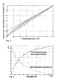
- FIG. 2 shows a typical course of a radiator heating power reserve or a radiator operating power ratio as a function of the mass flow of a radiator for a typical flow temperature, which is based on the design mass flow.
- the heating power reserve decreases with increasing mass flow, because the difference to the maximum possible mass flow through the radiator is smaller and the heat output depends on the mass flow.
- Fig. 5 shows the course of the radiator heating power reserve or the radiator operating ratio as a function of the current logarithmic overtemperature.
- the heating circuit heating reserve HLR is calculated for each controllable heating circuit from all the individual values of the radiator heating power reserve HLR_HK assigned to this heating circuit by weighted averaging and / or by applying a fuzzy logic in a module 6 for calculating the heating circuit heat capacity reserve.
- the weighting or the fuzzy logic is designed such that radiators 2 with a low heat capacity reserve HLR_HK or with a high performance ratio BLV_HK are weighted more heavily.
- HLR 1 ⁇ N_HK G HK ⁇ ⁇ N_HK G HK ⁇ HLR HK .
- BLV HK individual values of the radiator heating power reserves; N_HK ... Number of radiators considered.
- a XS_BLV TA_MAX - XS_BLV TA_MIN / TA_MAX - TA_MIN
- b XS_BLV TA_MAX - a ⁇ TA_MAX ⁇ Aussent ... Outside temperature; TA_M ... highest outside temperature (eg heating limit temperature); TA_MIN ... lowest outside temperature (eg design temperature); XS_BLV_TA_MAX ... BLV setpoint corresponding to TA_MAX; XS_BLV_TA_MIN ... BLV setpoint corresponding to TA_MIN.
- quasi-stationary algorithms can be used which take into account the dependence of the heating power reserve HLR and thus also the correction quantity DX on the outside temperature.
- the correction quantity DX is converted into a manipulated variable for direct influencing of the heating system in an example, as a controller of the flow temperature T VL and / or the mass flow m interface 11, which may have the outside temperature as well as the optimizer 10 as an additional input variable.
- the resulting sizes are in the in Fig. 1 illustrated example, the flow temperature T VL and the mass flow m.
- the heating power reserve available in the heating system 1 at the respective radiators 2 is optimized, and a control optimized for the available heat output and adapted for a heating system 1 is made available.
- a device 12 according to the invention for adjusting the heating power reserve is described below.
- This has a regulator 4 according to the invention for determining a correction or prospective variable DX, such as, for example, a change in the flow temperature T VL or mass flow m, which is a Schuungsregier 13 a heating system 1 is supplied.
- a correction or prospective variable DX such as, for example, a change in the flow temperature T VL or mass flow m, which is a Schuungsregier 13 a heating system 1 is supplied.
- the heating system 1 is constructed in the illustrated example of two heating circuits 14, each with a flow 15 to the individual radiators 2 and a return from the radiators 2 back to the heating system 1.
- a Bankauerverteiler 3 is arranged, which detects the radiator temperatures as described above and forwards temperature data collector 19 in the radio reception area of the heating cost allocator. 3 the radiator 2 are arranged.
- Such temperature data collectors 19 are often already used to detect the amount of heat emitted by the respective radiator 2, for which purpose the corresponding excess temperatures ⁇ are calculated in the heat cost allocator 3 or the data collector 19. These excess temperatures ⁇ are transferred in accordance with the device 12 according to the invention to a controller 4 for determining a correction or reference variable or also the manipulated variable, which is provided with a module 5 for calculating radiator heating power reserves From this, first a radiator heating capacity reserve HLR_HK assigned to each individual radiator 2 is calculated, which are then combined in a module 6 for calculating the heating circuit heating capacity reserves HLR. This heating circuit heating capacity reserve HLR is transmitted as a controlled variable to a module 8 for determining the desired heating power reserve and the control variable acting on the heating system, which operates as described above.
- the individual modules data collector, heat cost allocator and other devices communicate as well as an additionally provided outside temperature sensor 20 by means of wireless communication, which allows a particularly simple, especially also subsequent installation in buildings.
- the method according to the invention and the device 12 according to the invention can be easily retrofitted, in particular in heating systems 1, which have already been equipped with electronic and communication-capable heat cost allocators 3 and transmit the required temperature data.
- no process-specific characteristics for the determination of supply states need to be determined. This eliminates the considerable metrological effort in the determination of coefficients and parameters for calculating the supply states.
- the method according to the invention can be used in heating installations 1 with a variable installation location of the radiator sensors or radiator heat cost allocators, since the determination of the heating power reserve is independent of this. Thus, there is a particularly easy retrofitting in existing heating systems.
Abstract
Description
Die Erfindung betrifft ein Verfahren und eine Vorrichtung zur Einstellung der Heizleistungsreserve an den Heizkörpern und/oder in einem Heizkreis einer insbesondere einen oder mehrere regelbare Heizkreise aufweisenden Heizungsanlage, beispielsweise einer Warmwasserheizungsanlage.The invention relates to a method and a device for adjusting the Heizleistungsreserve to the radiators and / or in a heating circuit of a particular one or more controllable heating circuits having heating system, such as a hot water heating system.
Bei derartigen Heizungsanlagen erfolgt die Leistungsanpassung der zentralen Heizungsversorgung typischerweise durch Veränderung der Vorlauftemperatur oder des Massestromes des als Heizmittel dienenden flüssigen Wärmeträgers (meist Wasser) bzw. durch eine Kombination der Veränderung von Vorlauftemperatur und Massestrom. Die Regelung der Raumtemperatur erfolgt in einer derartigen Heizungsanlage mittels Variation des Heizkörpermassestromes, d.h. des Massestromes des Heizmittels durch den Heizkörper selbst. Typischerweise erfolgt bei derartigen Anlagen die Erfassung und Verteilung der Wärmemenge für die Raumheizung mittels elektronischer Heizkostenverteiler nach dem 2- oder 3-Fühlerprinzip.In such heating systems, the power adjustment of the central heating supply is typically done by changing the flow temperature or the mass flow of serving as a heating liquid heat carrier (usually water) or by a combination of change in flow temperature and mass flow. The regulation of the room temperature takes place in such a heating system by means of variation of the radiator mass flow, i. the mass flow of the heating medium through the radiator itself. Typically, in such systems, the detection and distribution of the amount of heat for space heating by means of electronic heat cost allocators on the 2- or 3-sensor principle.
Das Anwendungsgebiet der vorliegenden Erfindung betrifft somit insbesondere Heizungsanlagen, in denen an den Heizkörperzuleitungen
- a) die Variation des Massestromes mittels Heizkörperventilen erfolgt,
- b) die Regelung der Raumtemperatur mit Thermostatventilen erfolgt,
- c) die Regelung der Raumtemperatur mit elektronisch gesteuerten Ventilen erfolgt,
- d) die Variation des Massestromes mittels elektronisch gesteuerter Pumpen erfolgt und/oder
- e) die Regelung der Raumtemperatur mit elektronisch gesteuerten Pumpen erfolgt
- f) elektronische Heizkostenverteiler nach dem 2-Fühlerprinzip installiert sind, welche jeweils eine heizkörper- und eine raumluftseitige Temperatur erfassen oder
- g) elektronische Heizkostenverteiler nach dem 3-Fühlerprinzip oder andere geeignete Geräte installiert sind, welche die Heizmittelvorlauf-, die Heizmittelrücklauf- und die Raumlufttemperatur oder die Heizmittelvorlauf- und eine heizkörperseitige und eine raumluftseitige Temperatur oder die Heizmittelrücklauf- und eine heizkörperseitige und eine raumluftseitige Temperatur erfassen.
- a) the variation of the mass flow takes place by means of radiator valves,
- b) the regulation of the room temperature takes place with thermostatic valves,
- c) the regulation of the room temperature takes place with electronically controlled valves,
- d) the variation of the mass flow takes place by means of electronically controlled pumps and / or
- e) the control of the room temperature with electronically controlled pumps
- f) electronic heat cost allocators are installed according to the 2-sensor principle, which each detect a radiator side and a room air side temperature or
- g) electronic heat cost allocators are installed according to the 3-sensor principle or other suitable devices which detect the Heizmittelvorlauf-, the Heizmittelrücklauf- and the room air temperature or Heizmittelvorlauf- and a radiator side and a room air side temperature or the Heizmittelrücklauf- and a radiator side and a room air side temperature ,
Somit ist die vorliegende Erfindung in nahezu allen Heizungsanlagen, insbesondere Warmwasserheizungsanlagen, einsetzbar, da diese aufgrund der geltenden Vorschriften die vorstehenden Merkmale bereits aufweisen oder entsprechende Einrichtungen leicht nachinstalliert werden können.Thus, the present invention in almost all heating systems, especially hot water heating systems, can be used, since these already have the above features due to the current regulations or appropriate facilities can be easily installed.
In derzeit üblichen Warmwasserheizungsanlagen wird die Raumlufttemperatur mittels einer Variation des Heizmittelstromes durch die Heizkörper eingestellt. Zu diesem Zweck werden in den Zuleitungen zu den Heizkörpern entweder elektronisch oder thermostatisch betriebene Heizkörperventile oder auch elektronisch betriebene dezentrale Pumpen eingesetzt. In der überwiegenden Zahl der heute installierten Warmwasserheizungsanlagen wird die Vorlauftemperatur der Heizungsanlage nach der Außentemperatur und die zentrale Heizungsumwälzpumpe drehzahlkonstant oder nach einem Sollwert des Differenzdrucks über der Pumpe geführt. Eine Anpassung der an die Gebäudeheizungsanlage bzw. die einzelnen Heizkreise übergebenen Heizleistung an den tatsächlichen Bedarf erfolgt bei diesen Heizungsanlagen noch nicht.In currently customary hot water heating systems, the room air temperature is adjusted by means of a variation of the heating medium flow through the radiator. For this purpose, either electronically or thermostatically operated radiator valves or electronically operated decentralized pumps are used in the leads to the radiators. In the vast majority of hot water heating systems installed today, the flow temperature of the heating system is guided according to the outside temperature and the central heating circulation pump speed constant or after a target value of the differential pressure across the pump. An adaptation of the transferred to the building heating system or the individual heating circuits heating power to the actual needs is not yet in these heating systems.
Beispielsweise aus der
Diese vorgenannten Verfahren setzten jedoch entweder die Kenntnis der Hubstellungen der Heizkörperventile oder die Kenntnis von Heizkörpertemperaturen in Kombination mit zuvor ermittelten Kennlinien voraus. Die Kenntnis der Ventilhubstellungen ist nicht in jeder Heizungsanlage einfach zu erreichen. Die Ermittlung von Kennlinien, die in Verbindung mit leicht ermittelbaren Heizkörpertemperaturen ebenso eine bedarfsgeführte Anpassung der Vorlauftemperatur oder des Massestroms der Heizungsanlage ermöglichen, ist auch mit einem hohen messtechnischen Aufwand typischerweise auf Heizkörperprüfständen verbunden. Die ermittelten Kennlinien gelten ferner nur für die dem Messaufbau entsprechenden Positionen der Heizkostenverteiler auf der Heizkörperoberfläche, beispielsweise 0,5 Heizkörperlänge und 0,75 Heizkörperhöhe.However, these aforementioned methods require either the knowledge of the stroke positions of the radiator valves or the knowledge of radiator temperatures in combination with previously determined characteristics. The knowledge of the valve lift positions is not easy to achieve in every heating system. The determination of characteristic curves, which, in conjunction with easily determinable radiator temperatures, also enable a demand-driven adaptation of the flow temperature or the mass flow of the heating system, is typically associated with a high metrological outlay on radiator test benches. The determined characteristic curves also apply only to the positions of the heat cost allocators on the radiator surface corresponding to the measuring setup, for example 0.5 radiator length and 0.75 radiator height.
Die
Aufgabe der vorliegenden Erfindung ist es daher, mit einfacheren Mitteln eine bedarfsgeführte Wärmebereitstellung in einer Heizungsanlage zu ermöglichen.Object of the present invention is therefore to enable a simpler means an on-demand heat supply in a heating system.
Diese Aufgabe wird erfindungsgemäß mit den Merkmalen der unabhängigen Ansprüche 1 und 10 durch ein Verfahren und eine Vorrichtung zur Einstellung der Heizleistungsreserve in einem Heizkreis gelöst. Dabei werden für mehrere, vorzugsweise jeden regelbaren Heizkörper eines Heizkreises der Heizungsanlage im laufenden Betrieb eine Heizkörper-Leistungsreserve bestimmt und aus den einzelnen Heizkörper-Heizleistungsreserven eine Heizkreis-Heizleistungsreserve als Regelgröße ermittelt. Ferner wird eine Soll-Heizleistungsreserve als Sollwert der Heizkreis-Heizleistungsreserve ermittelt bzw. vorgegeben. In einer Regelung der Heizleistungsreserve wird dann aus der Abweichung der Regelgröße Heizkreis-Heizleistungsreserve von dem Sollwert Soll-Heizleistungsreserve eine Führungs- oder Korrekturgröße zur Einwirkung auf den Heizkreis bzw. die dem Heizkreis durch die Heizungsanlage zur Verfügung gestellten Wärmeleistung ermittelt.This object is achieved with the features of the
Es hat sich erfindungsgemäß herausgestellt, dass durch die Berücksichtigung der vergleichsweise einfach zu ermittelnden Heizleistungsreserve der Heizkörper in einem Heizkreis eine Regelung für die Heizkreis-Heizleistungsreserve geschaffen werden kann, die die benötigte Heizleistungsreserve in dem Heizkreis für einen komfortablen Betrieb optimal einstellt und dabei als wärmebedarfsgeführte Regelung ein energetisch unsinniges und teures Überangebot von in der Heizungsanlage zur Verfügung gestellter Wärmemenge vermeidet. Im Falle mehrerer regelbarer Heizkreise in einer Heizungsanlage wird das vorgeschlagene Verfahren vorzugsweise für jeden regelbaren Heizkreis durchgeführt, so dass für jeden Heizkreis die optimale Wärmemenge eingestellt und damit die gesamte Heizungsanlage wärmebedarfsgeführt geregelt wird. Falls nur ein Heizkreis vorhanden ist, kann das Verfahren in Kessel-Heizungsanlagen auch für die bedarfsgeführte Regelung der Kesseltemperatur eingesetzt werden. Das in verschiedenen Varianten vorgeschlagene Verfahren stellt also eine Art Vorregelung für eine Heizungsregelung oder Heizungssteuerung dar, welche eine Vorlauftemperatur und/oder einen Massestrom des Heizmittels für einen Heizkreis beispielsweise außentemperaturgesteuert führt oder aufgrund anderer Regelgrößen eigenständig regelt. So wird eine optimierte Einstellung der Heizleistungsreserve in dem Heizkreis und insbesondere für die Heizkörper in dem Heizkreis sowie eine bedarfsoptimierte Regelung der Heizungsanlage mit hohem Heizkomfort geschaffen, da an den jeweiligen Heizkörpern eine ausreichende Regelreserve zur Verfügung steht.It has been found according to the invention that can be created by the consideration of comparatively easy to determine Heizleistungsreserve the radiator in a heating circuit control for Heizkreis-Heizleistungsreserve that optimally adjusts the required Heizleistungsreserve in the heating circuit for comfortable operation while doing as heat demand-guided control avoids an energetically nonsensical and expensive oversupply of heat provided in the heating system. In the case of several controllable heating circuits in a heating system, the proposed method is preferably carried out for each controllable heating circuit, so that adjusted for each heating circuit, the optimal amount of heat and thus the entire heating system is controlled by heat demand. If only one heating circuit is available, the process in boiler heating systems can also be used for the demand-controlled control of the boiler temperature. The proposed method in various variants thus represents a kind of pre-regulation for a heating control or heating control, which performs a flow temperature and / or a mass flow of the heating means for a heating circuit, for example, outside temperature control or independently based on other control variables. Thus, an optimized setting of the heating power reserve in the heating circuit and in particular for the radiator in the heating circuit and a demand-optimized control of the heating system with high heating comfort created because of the respective radiators sufficient control reserve is available.
Der Begriff "Heizleistungsreserve" soll dabei als eine Größe verstanden werden, welche die Differenz zwischen der Wärmeleistung bei aktueller Vorlauftemperatur und Nennmassestrom und aktueller Wärmeleistung des Heizkörpers in das Verhältnis zu einer Wärmeleistung bei aktueller Vorlauftemperatur und Nennmassestrom setzt. Anstelle der Heizleistungsreserve in der vorstehenden Definition kann auch des "Betriebsleistungsverhältnis" verwendet werden, welches die aktuelle Wärmeleistung des Heizkörpers in das Verhältnis zu einer Wärmeleistung bei aktueller Vorlauftemperatur und Nennmassestrom setzt. Der Zusammenhang zwischen "Heizleistungsreserve" und Betriebsleistungsverhältnis lässt sich durch die Beziehung "Heizleistungsreserve = 1- Betriebsleistungsverhältnis" herstellen. Beide einfach ineinander überführbare Größen können für den vorliegenden Zweck in gleicher Weise verwendet werden, so dass nachfolgend weitestgehend auf eine Differenzierung verzichtet wird und beide Größen vereinfachend als "Heizleistungsreserve" bezeichnet werden. Ferner soll der Begriff "Heizleistungsreserve" im Folgenden technisch äquivalente Begriffe und Definitionen umfassen, welche die Leistungsreserve eines Heizkörpers beschreiben, die sich aus der Leistung bei aktueller Vorlauftemperatur und Nennmassestrom erreichen ließe.The term "heating power reserve" is to be understood as a quantity that sets the difference between the heat output at the current flow temperature and nominal mass flow and current heat output of the radiator in relation to a heat output at the current flow temperature and nominal mass flow. Instead of the heating power reserve in the above definition, the "operating ratio" can be used, which sets the current heat output of the radiator in relation to a heat output at the current flow temperature and nominal mass flow. The relationship between "heating power reserve" and operating power ratio can be established by the relationship "heating power reserve = 1 operating ratio". Both sizes which can be simply converted into one another can be used in the same way for the present purpose, so that a differentiation is largely dispensed with below and both variables are referred to as "heating power reserve" for simplicity. Furthermore, the term "heating power reserve" in the following should include technically equivalent terms and definitions that describe the power reserve of a radiator, which could be achieved from the power at the current flow temperature and nominal mass flow.
Das erfindungsgemäß vorgeschlagene Verfahren eignet sich deshalb so gut für die Realisierung einer wärmeleistungsadaptiven Heizungsregelung, weil die Heizleistungsreserve für einen Heizkörper mit einfachen Mitteln bestimmt werden kann. So wird gemäß einer besonders bevorzugten Ausführungsform des erfindungsgemäßen Verfahrens vorgeschlagen, dass die Heizleistungsreserve für jeden Heizkörper aus für den Heizkörper gemessenen Temperaturen ermittelt wird, insbesondere aus den von Heizkostenverteilern oder anderen geeigneten Messvorrichtungen mit 2- oder 3 Fühlermessungen erfassten Temperaturdaten der Heizkörper, wie beispielsweise den Heizkörperübertemperaturen. Besonders einfach kann die Heizleistungsreserve erfindungsgemäß aus dem Verhältnis der aktuellen logarithmischen Übertemperatur zu der logarithmischen Übertemperatur bei aktueller Vorlauftemperatur und dem Nennmassestrom ermittelt werden, indem dieses Verhältnis mit dem für jeden Heizkörper beispielsweise aus seinen Datenblättern bekannten Heizkörperexponenten potenziert wird.Therefore, the proposed method according to the invention is so well suited for the realization of a heat-power-adaptive heating control, because the Heizleistungsreserve for a radiator can be determined by simple means. Thus, according to a particularly preferred embodiment of the method according to the invention, it is proposed that the heating power reserve for each radiator be determined from temperatures measured for the radiator, in particular from the temperature data of the radiators, such as the radiator temperature data recorded by heat cost allocators or other suitable measuring devices with 2 or 3 sensor measurements heating bodies temperatures. According to the invention, the heating power reserve can be particularly easily calculated from the ratio of the current logarithmic overtemperature to the logarithmic Excess temperature can be determined at the current flow temperature and the nominal mass flow by this ratio with the known for each radiator, for example, from its data sheets radiator exponentiated.
Die Ermittlung der Heizkreis-Heizleistungsreserve aus den einzelnen Heizkörper-Heizleistungsreserven kann erfindungsgemäß durch eine insbesondere gewichtete Mittelwertbildung oder durch die Anwendung einer Fuzzy-Logic erfolgen. Die gewichtete Mittelwertbildung oder eine Fuzzy-Logic ermöglichen eine stärkere Gewichtung von Heizkörpern mit geringerer Heizleistungsreserve (beziehungsweise hohem Betriebsleistungsverhältnis), um auch an diesen Heizkörpern eine ausreichende Heizleistungsreserve zur Verfügung zu stellen und den Heizungskomfort insgesamt zu verbessern.The determination of the Heizkreis-Heizleistungsreserve from the individual radiator heating power reserves can be carried out according to the invention by a particular weighted averaging or by the application of a fuzzy logic. The weighted averaging or a fuzzy logic allow a stronger weighting of radiators with lower heating power reserve (or high operating ratio) to provide even at these radiators sufficient heating power reserve available and to improve the overall heating comfort.
Als Korrekturgröße kann erfindungsgemäß eine Änderung der Vorlauftemperatur und/oder des Massestromes des Heizkreises verwendet werden. In einer alternativen Ausführungsform kann als Korrekturgröße auch eine Änderung des Sollwertes vor Vorlauftemperatur und/oder des Massestromes einer insbesondere nachgelagerten Heizungsregelung verwendet werden. In diesen Fällen wirkt die Korrekturgröße also als Korrektursignal auf einen eigenständigen Regler der Heizungsanlage, welcher die auf die Heizungsanlage unmittelbar einwirkende Stellgröße erzeugt.As a correction variable, a change in the flow temperature and / or the mass flow of the heating circuit can be used according to the invention. In an alternative embodiment, a correction of the setpoint value can be used before the flow temperature and / or the mass flow of a particular downstream heating control. In these cases, the correction value thus acts as a correction signal to an independent controller of the heating system, which generates the directly acting on the heating system control variable.
Als Führungsgröße kann auch der Sollwert der Vorlauftemperatur und/oder des Massestroms verwendet werden und somit bspw. unmittelbar eine Führungsgröße für den Wärmeerzeuger, wie einen Heizkessel, oder Wärmeübertrager der Heizungsanlage, wie im Rahmen einer Fernwärmeheizung, sein.As a reference variable, the desired value of the flow temperature and / or the mass flow can be used and thus, for example. Immediately a reference variable for the heat generator, such as a boiler, or heat exchanger of the heating system, as part of a district heating.
Sowohl bei Anwendung einer Führungs- als auch einer Korrekturgröße kann die Heizungsanlage eine außentemperaturgeführte Heizungsanlage sein, so dass die resultierende Stellgröße beispielsweise eine Verschiebung der verwendeten Heizkennlinie bewirkt.Both when using a management and a correction variable, the heating system can be an outdoor temperature-controlled heating system, so that the resulting manipulated variable causes, for example, a shift in the heating characteristic used.
Mit diesen vorbeschriebenen Möglichkeiten zur Einwirkung auf die Heizungsanlage werden typische Fälle herkömmlicher Heizungsanlagen abgedeckt. Erfindungsgemäß ist die vorgeschlagene Lösung jedoch nicht auf diese Arten beschränkt. Wesentlich ist, dass eine auf den Wärmeerzeuger bzw. Wärmeverteiler einer Heizungsanlage einwirkende Führungs- oder Korrekturgröße erzeugt und in eine Stellgröße umgesetzt wird, die in einer eigenständigen, der Heizungsregelung oder Heizungssteuerung vorgelagerten Regelung einen gewünschten Sollwert der Heizkreis-Heizleistungsreserve einstellt.With these above-described possibilities for acting on the heating system typical cases of conventional heating systems are covered. However, according to the invention, the proposed solution is not limited to these types. It is essential that a control or correction variable acting on the heat generator or heat distributor of a heating system is generated and converted into a manipulated variable which adjusts a desired desired value of the heating circuit heating power reserve in an independent regulation preceding the heating control or heating control.
Gemäß einer besonders bevorzugten Ausführungsform des erfindungsgemäßen Verfahrens kann die Soll-Heizleistungsreserve als Sollwert der Regelgröße Heizkreis-Heizleistungsreserve für den bzw. jeden regelbaren Heizkreis in Abhängigkeit der Außentemperatur, der Vorlauftemperatur und/oder der Tageszeit gleitend geführt werden. Hierdurch lässt sich mit einfachen Mitteln eine wesentliche Komfortverbesserung gegenüber den bekannten Verfahren zur Regelung einer Heizungsanlage erreichen, bei denen insbesondere für Anheizprozesse, die typischerweise nach Phasen einer sogenannten Nachtabsenkung (gezielte zeitliche Absenkung der Vorlauftemperatur um einen festen Betrag, typischerweise 5 bis 10 Kelvin in einem Zeitraum zwischen etwa 23 Uhr und 5 Uhr) oder nach längeren Abwesenheitszeiten der Bewohner auftreten, besonders hohe Heizleistungen erforderlich sind. Diese besonders hohen Heizleistungen müssen typischerweise innerhalb von ein bis zwei Stunden bereitgestellt werden, da die berechtigten Komfortanforderungen der Bewohner ein Aufheizen der Nutzräume auf Raum-Solltemperatur innerhalb von ein bis zwei Stunden vorsehen, wie in der Norm DIN EN 12831 angegeben.According to a particularly preferred embodiment of the method according to the invention, the desired heat capacity reserve as a setpoint of the control variable heating circuit heating power reserve for the or each controllable heating circuit depending on the outside temperature, the flow temperature and / or the time of day are guided. This can be achieved with simple means a significant improvement in comfort over the known methods for controlling a heating system, which in particular for Anheizprozesse, typically after phases of a so-called night reduction (targeted time reduction of the flow temperature by a fixed amount, typically 5 to 10 Kelvin in one Period between about 23 o'clock and 5 o'clock) or after longer absences of the inhabitants occur, particularly high heat outputs are necessary. These particularly high heat outputs typically need to be provided within one to two hours as the occupants' legitimate comfort requirements provide for heating the utility rooms to room setpoint temperatures within one to two hours, as specified in the DIN EN 12831 standard.
Die aktuelle Außentemperatur und - wegen der Abhängigkeit von der Heizkurve gemäß
Dabei kann zusätzlich vorgesehen sein, dass die Zeitabhängigkeit der Soll-Heizleistungsreserve für den bzw. jeden regelbaren Heizkreis tagestyp- und tageszeitabhängig selbsttätig erlernt wird, indem das Nutzungsverhalten in den beispielsweise letzten zwei Wochen oder über einen anderen geeigneten Zeitraum extrapoliert wird.In this case, it may additionally be provided that the time dependency of the desired heating power reserve for the or each controllable heating circuit is learned automatically on a daytime and daytime basis by extrapolating the usage behavior in, for example, the last two weeks or over another suitable period.
Erfindungsgemäß kann aus der Regelabweichung zwischen der Heizkreis-Heizleistungsreserve und der Soll-Heizleistungsreserve mittels eines P- oder PI-Regelgesetzes oder mittels quasi stationärer Algorithmen, welche insbesondere die Abhängigkeit der Heizleistungsreserve von der Außentemperatur berücksichtigen können, eine Korrektur- oder Führungsgröße zur Vorgabe der Stellgröße ermittelt werden. Dies kann in einem Optimierer erfolgen. Der Vorgang kann zweistufig ablaufen, indem zunächst eine Korrekturgröße (insbesondere Änderung der Vorlauftemperatur und/oder des Massestroms) ermittelt wird, die anschließend in eine Führungsgröße (insbesondere resultierende Sollwerte für die die Vorlauftemperatur und/oder den Massestrom nach erfolgter Korrektur) überführt wird. Erfindungsgemäß können Korrektur- und Stellgröße jedoch auch identisch sein und in einem einstufigen Prozess bestimmt werden. Anschließend wird die resultierende Führungsgröße in eine an die jeweilige Heizungsanlage angepasste Stellgröße (bspw. Pumpendrehzahl, Stellventilhub in dem Heizungsanlagen-Vorlauftemperaturregler) umgewandelt.According to the invention, from the control deviation between the heating circuit heating power reserve and the desired heating power reserve by means of a P or PI control law or quasi stationary algorithms, which can take into account in particular the dependence of the heating power reserve of the outside temperature, a correction or reference variable for specifying the manipulated variable be determined. This can be done in an optimizer. The process can be carried out in two stages by first determining a correction variable (in particular a change in the flow temperature and / or the mass flow), which is subsequently converted into a reference variable (in particular resulting setpoint values for the flow temperature and / or the mass flow after correction has taken place). However, according to the invention, correction and manipulated variable can also be identical and determined in a single-stage process. Subsequently, the resulting reference variable in one of the respective heating system adapted control variable (eg., Pump speed, Stellventilhub in the heating system flow temperature controller) converted.
Die Erfindung betrifft insbesondere auch eine Vorrichtung zur Einstellung der Heizleistungsreserve in einem Heizkreis oder mehreren Heizkreisen einer Heizungsanlage mit einem Regler zur Ermittlung einer Korrektur- oder Führungsgröße zur Einwirkung auf den Heizkreis bzw. die dem Heizkreis oder den Heizkreisen durch die Heizungsanlage zur Verfügung gestellten Wärmeleistung. Hierzu ist erfindungsgemäß vorgesehen, dass der Regler ein Modul zur Berechnung von Heizkörper-Heizleistungsreserven aus Heizkörpertemperaturwerten inklusive Vor- oder Rücklauftemperaturen, ein Modul zur Berechnung einer Heizkreis-Heizleistungsreserve aus den einzelnen Heizkörper-Heizleistungsreserven und ein Modul zur Ermittlung einer Soll-Heizleistungsreserve und zur Auswertung einer Regelabweichung zwischen der Soll-Heizleistungsreserve und der Heizkörper-Heizleistungsreserve für die Ermittlung einer Stellgröße aufweist. Die vorgenannten Module sind insbesondere zur Durchführung des vorbeschriebenen Verfahrens eingerichtet und können durch in einem oder mehreren Moduleinheiten vorgesehene Recheneinheiten, beispielsweise Mikrocontroller, realisiert werden.In particular, the invention also relates to a device for adjusting the heating power reserve in a heating circuit or a plurality of heating circuits of a heating system with a controller for determining a correction or reference variable for acting on the heating circuit or the heat output provided by the heating system to the heating circuit or heating circuits. For this purpose, the invention provides that the controller is a module for calculating radiator heating power reserves from radiator temperature values including flow or return temperatures, a module for calculating a Heizkreis-Heizleistungsreserve from the individual Heizkörper-Heizleistungsreserven and a module for determining a desired Heizleistungsreserve and for evaluation a control deviation between the desired heating capacity reserve and the radiator heating power reserve for the determination of a manipulated variable has. The abovementioned modules are set up in particular for carrying out the method described above and can be realized by computing units, for example microcontrollers, provided in one or more module units.
Erfindungsgemäß weist die Vorrichtung auch an die Heizkörper angeschlossene Messeinrichtungen, insbesondere Heizkostenverteiler, zur Erfassung der Heizkörpertemperaturen und mindestens einen damit verbundenen Datensammler auf, wobei der Datensammler mit dem Modul zur Berechnung der Heizkörper-Heizleistungsreserven verbunden ist. Vorzugsweise ist auch mindestens ein Vorlauftemperaturfühler an dem Vorlauf der Heizungsanlage oder dem oder jedem Heizkreis zu Erfassung der Vorlauftemperaturen vorgesehen.According to the invention, the device also has measuring devices connected to the radiators, in particular heat cost allocators, for detecting the radiator temperatures and at least one associated data collector, the data collector being connected to the module for calculating the radiator heating power reserves. Preferably, at least one flow temperature sensor is provided at the flow of the heating system or the or each heating circuit to detect the flow temperatures.
Ferner ist der Regler gemäß einer bevorzugten Ausführungsform der Erfindung direkt mit einer Heizungsanlage verbunden. In dieser Verbindung stellt die erfindungsgemäße Vorrichtung insbesondere auch eine Wärmeleistungsadaptionsregelung für eine Heizungsanlage dar, in welcher der Regler unmittelbar dazu eingerichtet ist, eine konkrete Heizungsanlage mit Korrektur- oder Führungsgrößen zu versorgen.Furthermore, the controller is connected directly to a heating system according to a preferred embodiment of the invention. In this connection, the inventive Device in particular also a heat capacity adaptation control for a heating system, in which the controller is set up directly to provide a specific heating system with correction or reference variables.
Die Verbindung zwischen den einzelnen Modulen, Messeinrichtungen und/oder dem oder den Datensammler(n) ist gemäß einer bevorzugten Ausführungsform der Erfindung eine Funkverbindung, kann jedoch ganz oder teilweise auch durch andere Kommunikationsverbindungen ersetzt sein. Hierfür kommen elektrische Kabel- oder Busverbindungen, optische Verbindungen oder dergleichen in Frage.The connection between the individual modules, measuring devices and / or the data collector (s) is in accordance with a preferred embodiment of the invention, a radio link, but may be completely or partially replaced by other communication links. For this purpose, electrical cable or bus connections, optical connections or the like in question.
Auch können einzelne Module oder Geräte zusammengefasst sein, so dass die verschiedenen Teilaufgaben der Module durch dieselbe Recheneinheit ausgeführt wird, die zur Durchführung der unterschiedlichen Verfahrensschritte eingerichtet ist. Beispielsweise kann durch die Zusammenfassung der Berechnungsmodule mit den Datensammlern dahingehend ein synergetischer Effekt erreicht werden, dass die für die Berechnungen der einzelnen Heizkörper-Heizleistungsreserven notwendigen Temperaturdaten der Heizkörper ohnehin vorhanden sind.Also, individual modules or devices can be combined, so that the various subtasks of the modules is performed by the same computing unit that is set up to perform the different process steps. For example, by combining the calculation modules with the data collectors, a synergistic effect can be achieved in such a way that the temperature data of the radiators necessary for the calculations of the individual radiator heating power reserves are available anyway.
Weitere Merkmale, Vorteile und Anwendungsmöglichkeiten der vorliegenden Erfindung ergeben sich auch aus der nachfolgenden Beschreibung eines Ausführungsbeispiels und der Zeichnung. Dabei bilden alle beschriebenen und/oder bildlich dargestellten Merkmale für sich oder in beliebiger Kombination den Gegenstand der vorliegenden Erfindung, auch unabhängig von ihrer Zusammenfassung in den Ansprüchen oder deren Rückbezügen.Other features, advantages and applications of the present invention will become apparent from the following description of an embodiment and the drawing. All described and / or illustrated features alone or in any combination form the subject matter of the present invention, also independent of their summary in the claims or their back references.
Es zeigen:
- Fig. 1
- einen Signalflussplan für das erfindungsgemäße Verfahren zur Einstellung der Heizleistungsreserve;
- Fig. 2
- eine erfindungsgemäße Vorrichtung zur Einstellung der Heizleistungsreserve in Heizkreisen;
- Fig. 3
- herkömmliche stationäre Heizungskurven;
- Fig. 4
- das Heizkörper-Betriebsleistungsverhältnis und die Heizkörper-Heizleistungsreserve aufgetragen gegen den Heizkörpermassestrom bei einer Vorlauftemperatur;
- Fig. 5
- das Heizkörper-Betriebsleistungsverhältnis und die Heizkörper-Heizleistungsreserve aufgetragen gegen die aktuelle logarithmische Übertemperatur;
- Fig. 6
- das Soll-Betriebsleistungsverhältnisses und die Soll-Heizleistungsreserve aufgetragen gegen die Außentemperatur.
- Fig. 1
- a signal flow plan for the inventive method for adjusting the heating power reserve;
- Fig. 2
- an inventive device for adjusting the Heizleistungsreserve in heating circuits;
- Fig. 3
- conventional stationary heating curves;
- Fig. 4
- the radiator operating power ratio and the radiator heating power reserve plotted against the radiator mass flow at a flow temperature;
- Fig. 5
- the radiator operating power ratio and the radiator heating power reserve plotted against the current logarithmic overtemperature;
- Fig. 6
- the desired operating power ratio and the desired heating power reserve plotted against the outside temperature.
In
Jedem Heizkörper 2.1 bis 2.n ist zur Erfassung der abgegebenen Wärmemenge ein Heizkostenverteiler 3.1 bis 3.n zugeordnet, welcher heizkörperseitige Temperaturen THKS und raumluftseitige Temperaturen TRLS messen und hieraus Heizkörperübertemperaturen Δ ermittelt. Abweichend von der Darstellung in
Bei den Heizkostenverteilern 3 kann es sich um beispielsweise funkkommunikationsfähige Heizkostenverteiler nach dem 2- oder 3-Fühlerprinzip oder andere geeignete Messvorrichtungen zur Erfassung und Übertragung von 2- oder 3-Heizkörpertemperaturen handeln.The
Entsprechend der verschiedenen Ausführungsformen der Heizkostenverteiler 3 gibt es verschiedene Möglichkeiten zur Berechnung der Heizkörperübertemperatur Δ.According to the various embodiments of the
In einer ersten Variante lässt sich eine logarithmische Heizkörperübertemperatur Δlog für Heizkostenverteiler nach dem 2-Fühlerprinzip wie folgt berechnen: 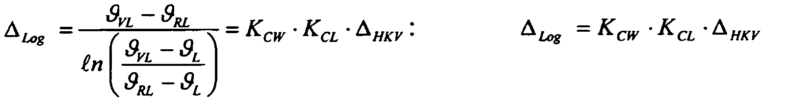
mit
![]()

![]()
With ![]()
![]()
Die heizkörperspezifischen Korrekturfaktoren KCW und KCL werden aus den entsprechenden heizkörperspezifischen C-Werten berechnet, die für jeden Heizkörper in der gängigen Praxis der Heizkostenerfassung sowieso bekannt sind. In der heutigen Praxis der Heizkostenverteilung werden als C-Werte bzw. als Korrekturfaktoren feste Werte verwendet.The radiator-specific correction factors K CW and K CL are calculated from the corresponding radiator-specific C values, which are known anyway for any radiator in the common practice of heating cost recording. In today's practice of heating cost distribution, fixed values are used as C values or as correction factors.
Alternativ kann die Berechnung der logarithmischen Heizkörperübertemperatur Δlog für Heizkostenverteiler nach dem 2-Fühlerprinzip in einer zweiten Variante auch wie folgt erfolgen: 
wobei
![]()
![]()
![]()
![]()
in which ![]()
![]()
![]()
![]()
Die Rücklaufübertemperatur ΔϑRL wird aus der theoretischen Heizkörpergleichung ![]()
![]()
![]()
mit
![]()
![]()
![]()
![]()
![]()
![]()
With ![]()
![]()
![]()
Ähnlich kann die Berechnung der logarithmischen Heizkörperübertemperatur Δlog für Heizkostenverteiler nach dem 3-Fühlerprinzip in einer ersten Variante erfolgen: 
wobei
in which
Anstelle von Heizkostenverteilern kann auch ein Messvorrichtung zum Einsatz kommen, die folgende Temperaturen erfasst:
In einer zweiten Variante des 3-Fühler-Prinzips kann die Heizkörperübertemperatur Δ log wie folgt berechnet werden; 
wobei
![]()
![]()
![]()
![]()
![]()
![]()
![]()
mit:
![]()
in which ![]()
![]()
![]()
![]()
![]()
![]()
![]()
With: ![]()
Die Messung von ϑVL oder/und ϑHK (h) oder/und ϑ Luft kann mit beliebiger Messtechnik erfolgen.The measurement of θ VL or / and θ HK ( h ) or / and θ air can be done with any measuring technique.
Ferner wird eine logarithmischen Heizkörperübertemperatur Δlog,100 bei Nennmassestrom (bei Nennmassestrom oder Auslegungsmassestrom) wie folgt ermittelt: 
wobei:
![]()
![]()
![]()
![]()
![]()
in which: ![]()
![]()
![]()
![]()
![]()
Der Nenn. oder Auslegungsmassenstrom wird als 
definiert mit:
![]()
![]()
![]()
![]()
defined with: ![]()
![]()
![]()
![]()
Für Auslegungspunkt gilt: xP = AP. Die Auslegungsparameter der Heizungsanlage ΔRL,AP' ΔVL,AP sind typischerweise aus den Planungsunterlagen bekannt. Ersatzweise können auch die Heizkörperparameter des Normpunktes (Vorlauf/Rücklauf/Luft-Temperatur = 90/70/20 °C) nach DIN EN 442 verwendet werden:
![]()
![]()
![]()
![]()
![]()
![]()
Mit diesen wie zuvor beschrieben bestimmten Heizkörperübertemperaturen Δ ermittelt ein in der erfindungsgemäßen Vorrichtung vorgesehener Regler 4 zur Ermittlung einer Stellgröße zur Einwirkung auf den Heizkreis der Heizungsanlage 1 in einem Modul 5 für jeden Heizkörper 2.1 bis 2.n eine Heizkörper-Heizleistungsreserve HLR_HK.With these radiator overtemperatures Δ determined as described above, a
Die Heizkörper-Heizleistungsreserve HLR_HK kann dabei wie folgt bestimmt werden, wobei zunächst ein Heizkörper-Betriebsleistungsverhältnis BLV_HK entsprechend folgender Beziehung ausgerechnet wird: 
mit
With
Das Heizkörper-Betriebsleistungsverhältnis BLV_HK ergibt sich also in einfacher Weise aus dem Verhältnis von Heizköperübertemperaturen Δ. Das Heizkörper-Betriebsleistungsverhältnis BLV_HK lässt sich über die Beziehung ![]()
einfach in eine Heizkörper-Heizleistungsreserve HLR_HK umrechnen. Da beide Größen äquivalent sind, wird nachfolgend meist nur von "Heizleistungsreserve" gesprochen. Diese Terminologie schließt die in dem Regler 4 in gleicher Weise verwendbare Größe Betriebsleistungsverhältnis mit ein.The radiator operating power ratio BLV_HK thus results in a simple manner from the ratio of Heizköperübertemperaturen Δ. The radiator operating power ratio BLV_HK can be over the relationship ![]()
Simply convert to a radiator heating capacity reserve HLR_HK. Since both sizes are equivalent, the following is usually only spoken by "heating power reserve". This terminology includes the size of the power ratio to be used in the
In
Die Berechnung der Heizkreis-Heizieistungsreserven HLR erfolgt für jeden regelbaren Heizkreis aus allen Einzelwerten der diesem Heizkreis zugeordneten Heizkörper-Heizleistungsreserven HLR_HK mittels gewichteter Mittelwertbildung und/oder durch Anwendung einer Fuzzy-Logic in einem Modul 6 zur Berechnung der Heizkreis-Heizleistungsreserve.The heating circuit heating reserve HLR is calculated for each controllable heating circuit from all the individual values of the radiator heating power reserve HLR_HK assigned to this heating circuit by weighted averaging and / or by applying a fuzzy logic in a
Dabei wird im Sinne der Vermeidung von Diskomfortzuständen im Ergebnis der Verfahrensanwendung die Gewichtung bzw. die Fuzzy-Logic so entworfen, dass Heizkörper 2 mit geringer Heizleistungsreserve HLR_HK bzw. mit hohem Betriebsleistungsverhältnis BLV_HK stärker gewichtet werden.In this case, in the sense of avoiding discomfort conditions as a result of the method application, the weighting or the fuzzy logic is designed such that
Als Maß für hohe oder kleine Heizleistungsreserve gilt der Sollwert für die Heizleistungsreserve XS_HLR, der in einem nachfolgend nach näher beschriebenen Modul 7 zur Sollwertbestimmung erzeugt wird:
- HLR_HK < XS_HLR: kleine HLR -> hohe Gewichtung (g>1);
- HLR_HK = XS_HLR: Soll-HLR -> Nenn-Gewichtung (g=1);
- HLR_HK > XS_HLR: große HLR -> kleine Gewichtung (g< 1);
- HLR_HK <XS_HLR: small HLR -> high weighting (g>1);
- HLR_HK = XS_HLR: Target HLR -> nominal weighting (g = 1);
- HLR_HK> XS_HLR: large HLR -> small weight (g <1);
Entsprechendes gilt natürlich für den Sollwert für das Betriebsleistungsverhältnis XS_BLV:
- BLV_HK> XS_BLV: großes BLV -> hohe Gewichtung (g>1)
- BLV_HK = XS_BLV: Soll-BLV -> Nenn-Gewichtung (g=1)
- BLV_HK < XS_BLV: kleines BLV -> kleine Gewichtung (g<1)
- BLV_HK> XS_BLV: big BLV -> high weighting (g> 1)
- BLV_HK = XS_BLV: Target BLV -> nominal weighting (g = 1)
- BLV_HK <XS_BLV: small BLV -> small weighting (g <1)
Für die gewichtete Mittewertbildung gilt: 
mit
HLRHK ... Einzelwerte der Heizkörper-Heizleistungsreserven
N_HK ... Anzahl der berücksichtigten Heizkörper
bzw. analog: 
mit
BLVHK ... Einzelwerte der Heizkörper-Heizleistungsreserven;
N_HK ... Anzahl der berücksichtigten Heizkörper.For weighted averaging:
With
HLR HK ... individual values of the radiator heating power reserves
N_HK ... Number of radiators considered
or analogously:
With
BLV HK ... individual values of the radiator heating power reserves;
N_HK ... Number of radiators considered.
Vorteilhaft ist jedoch die Verwendung gleitender Sollwerte, vorzugsweise in Abhängigkeit der Außentemperatur TA, da das Lüftungsverhalten der Nutzer außentemperaturabhängig ist (längere Lüftungsdauer bei höheren Außentemperaturen) und die installierten Heizleistungsreserven gemäß der Basis-Heizkennlinie entsprechend
Ein linearer Ansatz führt zu folgendem Ergebnis: ![]()
mit ![]()
![]()
![]()
With ![]()
![]()
Aus dem Soll-Betriebsleistungsverhältnis XS_BLV kann dann entsprechend die Soll-Heizleistungsreserve XS_HLR = 1 - XS_BLV. berechnet werden. Ein Berechnungsbeispiel für die Sollwerte in Abhängigkeit der Außentemperatur ist in
In einem Vergleicher 9 wird die Soll-Heizleistungsreserve XS_HLR; XS_BLV mit der Heizkreis-Heizleistungsreserve HLR; BLV verglichen und die Regelabweichung e durch Differenzbildung erzeugt. Aus dieser Regelabweichunge werden in einem Optimierer 10 Korrekturgrößen DX berechnet, wobei aus der Regelungstechnik bekannte Algorithmen verwendet werden.In a comparator 9, the desired heating power reserve XS_HLR; XS_BLV with the heating circuit heating capacity reserve HLR; BLV compared and the deviation e generated by subtraction. From this
Hierbei können ein P-Regelgesetz mit der Korrekturgröße: ![]()
oder ein PI-Regelgesetz mit der Korrekturgröße: 
zum Einsatz kommen. Alternativ oder ergänzend können quasistationäre Algorithmen eingesetzt werden, die die Abhängigkeit der Heizleistungsreserve HLR und damit auch der Korrekturgröße DX von der Außentemperatur berücksichtigen.Here, a P-law with the correction quantity: ![]()
or a PI control law with the correction quantity:
be used. Alternatively or additionally, quasi-stationary algorithms can be used which take into account the dependence of the heating power reserve HLR and thus also the correction quantity DX on the outside temperature.
Die Korrekturgröße DX wird in einer bspw. als Regler der Vorlauftemperatur TVL und/oder des Massestroms m Schnittstelle 11, die selbst ebenso wie der Optimierer 10 als zusätzliche Eingangsgröße die Außentemperatur aufweisen kann, in eine Stellgröße zur unmittelbaren Beeinflussung der Heizungsanlage umgewandelt. Die resultierenden Größen sind in dem in
Das vorstehend mit Bezug auf
- 1. Zyklische, d.h. sich zeitlich in bestimmten Abständen wiederholende Berechnung der Heizkreis-Heizleistungsreserve HLR (oder BLV) aus den Heizkörper-Heizleistungsreserven HLR_HK (oder BLV_HK);
- 2. Zyklische Berechnung des Sollwertes der Heizkreis-Heizleistungsreserve XSHLR (oder XSBLV);
- 3. Zyklische Berechnung der Korrektur von Vorlauftemperatur oder Massenstrom des entsprechenden Heizkreises.
- 1. Cyclic, ie repetitive at certain intervals calculation of the heating circuit heating capacity reserve HLR (or BLV) from the radiator heating power reserves HLR_HK (or BLV_HK);
- 2. Cyclical calculation of the setpoint of the heating circuit reserve power reserve XS HLR (or XS BLV );
- 3. Cyclic calculation of the correction of flow temperature or mass flow of the corresponding heating circuit.
Durch diese Maßnahmen wird die in der Heizungsanlage 1 an den jeweiligen Heizkörpern 2 zur Verfügung stehende Heizleistungsreserve optimiert und eine in Bezug auf die zur Verfügung stehende Wärmeleistung optimierte und adaptierte Regelung für eine Heizungsanlage1 zur Verfügung gestellt.As a result of these measures, the heating power reserve available in the
Zusammenfassend werden die wesentlichen Verfahrensschritte nachfolgend noch einmal kurz in der Übersicht dargestellt.In summary, the essential procedural steps are briefly outlined in the overview below.
Es wird also ein Verfahren zur automatischen Einstellung und Regelung der Heizleistungsreserve von Heizkörpern in Warmwasserheizungsanlagen vorgeschlagen, das
- (a) die Regelgröße 'Betriebsleistungsverhältnis' oder 'Heizleistungsreserve' analytisch ohne Kenntnis von Kennlinien berechnet;
- (b) die Regelgröße 'Betriebsleistungsverhältnis' oder 'Heizleistungsreserve' für jeden regelbaren Heizkreis aus den Einzelwerten 'Betriebsleistungsverhältnis' oder ,Heizleistungsreserve' der Einzelheizkörper ermittelt;
- (c) die Zwischengrößen 'Betriebsleistungsverhältnis' oder 'Heizleistungsreserve' für jeden Heizkörper aus gemessenen Temperaturen errechnet;
- (d) die Änderung des Sollwertes der Vorlauftemperatur oder des Massestromes der einzelnen regelbaren Heizkreise oder auch eine Kombination aus beiden als Stellgröße verwendet;
- (e) alternativ zu d) die Änderung der Vorlauftemperatur oder des Massestromes der einzelnen regelbaren Heizkreise oder auch eine Kombination aus beiden als Stellgröße verwendet;
- (f) den Sollwert der Regelgröße ,Betriebsleistungsverhältnis' oder ,Heizleistungsreserve' für jeden regelbaren Heizkreis in Abhängigkeit der Außentemperatur gleitend führt;
- (g) alternativ zu f) den Sollwert der Regelgröße ,Betriebsleistungsverhältnis' oder 'Heizleistungsreserve' für jeden regelbaren Heizkreis in Abhängigkeit der Vorlauftemperatur gleitend führt;
- (h) infolge sich wiederholender Tagesabläufe die Zeitabhängigkeit des Sollwert der Regelgröße 'Betriebsleistungsverhältnis' oder 'Heizleistungsreserve' für jeden regelbaren Heizkreis tagestyp- und tageszeitabhängig erlernt.
- (a) the control variable 'operating power ratio' or 'heating power reserve' calculated analytically without knowledge of characteristics;
- (b) the controlled variable 'operating power ratio' or 'heating power reserve' for each controllable heating circuit is determined from the individual values 'operating power ratio' or 'heating power reserve' of the individual heaters;
- (c) calculating the intermediate quantities 'operating power ratio' or 'heating power reserve' for each radiator from measured temperatures;
- (d) the change in the setpoint value of the flow temperature or the mass flow of the individual controllable heating circuits or a combination of both used as a control variable;
- (e) alternatively to d) the change in the flow temperature or the mass flow of the individual controllable heating circuits or a combination of both used as a control variable;
- (f) the target value of the controlled variable, operating power ratio 'or' Heizleistungsreserve 'for each controllable heating circuit in dependence on the outside temperature slidably leads;
- (g) as an alternative to f), the setpoint of the controlled variable 'operating power ratio' or 'heating power reserve' for each controllable heating circuit in a sliding manner depending on the flow temperature;
- (h) learns the time dependence of the setpoint of the control variable 'operating power ratio' or 'Heizleistungsreserve' for each controllable heating circuit day type and time of day as a result of repetitive daily routines.
Mit Bezug auf
Die Heizungsanlage 1 ist in dem dargestellten Beispiel aus zwei Heizkreisen 14 mit jeweils einem Vorlauf 15 zu den einzelnen Heizkörpern 2 und einem Rücklauf von den Heizkörpern 2 zurück zu der Heizungsanlage 1 aufgebaut. In dem Bereich des Vorlaufs 15 der Heizkreise 14 befinden sich Vorlauftemperaturfühler 17. An jedem Heizkörpern 2 in den verschiedenen Wohneinheiten 18 ist jeweils ein Heizkostenverteiler 3 angeordnet, der wie vorbeschrieben die Heizkörpertemperaturen erfasst und an Temperatur-Datensammler 19 weiterleitet, die im Funkempfangsbereich der Heizkostenverteiler 3 der Heizkörper 2 angeordnet sind.The
Derartige Temperatur-Datensammler 19 werden häufig bereits zur Erfassung der durch die jeweiligen Heizkörper 2 abgegebenen Wärmemenge eingesetzt, wozu die entsprechenden Übertemperaturen Δ in dem Heizkostenverteiler 3 oder dem Datensammler 19 berechnet werden. Diese Übertemperaturen Δ werden gemäß der erfindungsgemäßen Vorrichtung 12 an einen Regler 4 zur Ermittlung einer Korrektur- oder Führungsgröße bzw. auch der Stellgröße übertragen, der mit einem Modul 5 zur Berechnung von Heizkörper-Heizleistungsreserven hieraus zunächst eine jedem einzelnen Heizkörper 2 zugeordnete Heizkörper-Heizleistungsreserve HLR_HK berechnet, die dann in einem Modul 6 zur Berechnung der Heizkreis-Heizleistungsreserven HLR zusammengefasst werden. Diese Heizkreis-Heizleistungsreserve HLR wird als Regelgröße einem Modul 8 zur Ermittlung der Soll-Heizleistungsreserve und der auf die Heizungsanlage einwirkenden Stellgröße übermittelt, die wie vorbeschrieben arbeitet.Such
Die einzelnen Module Datensammler, Heizkostenverteiler und weiteren Geräte kommunizieren wie auch ein zusätzlich vorgesehener Außentemperaturfühler 20 mittels einer Funkkommunikation, die eine besonders einfache, insbesondere auch nachträgliche Installation in Gebäuden ermöglicht.The individual modules data collector, heat cost allocator and other devices communicate as well as an additionally provided
Damit sind das erfindungsgemäße Verfahren und die erfindungsgemäße Vorrichtung 12 insbesondere in Heizungsanlagen 1 einfach nachrüstbar, die bereits mit elektronischen und kommunikationsfähigen Heizkostenverteilern 3 ausgestattet wurden und die erforderlichen Temperaturdaten übertragen. Im Gegensatz zu bereits eingesetzten Verfahren zur Wärmeleistungsadaption müssen keine verfahrensspezifischen Kennlinien für die Ermittlung von Versorgungszuständen ermittelt werden. Hierdurch fällt der erhebliche messtechnische Aufwand bei der Bestimmung von Koeffizienten und Parametern zur Berechnung der Versorgungszustände weg. Ferner ist das erfindungsgemäße Verfahren in Heizungsanlagen 1 mit variablem Installationsort der Heizkörper-Fühler bzw. Heizkörper-Heizkostenverteiler einsetzbar, da die Ermittlung der Heizleistungsreserve hiervon unabhängig ist. Somit besteht eine besonders einfache Nachrüstbarkeit in bestehenden Heizungsanlagen.Thus, the method according to the invention and the
- 11
- Heizungsanlageheating system
- 22
- Heizkörper (HK)Radiator (HK)
- 33
- Heizkostenverteiler (HKV), MesseinrichtungHeating cost allocator (HKV), measuring equipment
- 44
- Regler zur Ermittlung einer Korrektur- oder FührungsgrößeController for determining a correction or reference variable
- 55
- Modul zur Berechnung von Heizkörper-HeizleistungsreservenModule for calculating radiator heating power reserves
- 66
- Modul zur Berechnung der Heizkreis-HeizleistungsreserveModule for calculating the heating circuit heating capacity reserve
- 77
- Modul zur SollwertbestimmungModule for setpoint determination
- 88th
- Modul zur Ermittlung von Soll-Heizleistungsreserve und Korrektur- oder FührungsgrößeModule for determining set heating power reserve and correction or reference variable
- 99
- Vergleichercomparator
- 1010
- Optimiereroptimizer
- 1111
- Schnittstelle, Regler von Vorlauftemperatur und/oder MassestromInterface, controller of flow temperature and / or mass flow
- 1212
- Vorrichtung zur Einstellung der HeizleistungsreserveDevice for adjusting the heating power reserve
- 1313
- HeizungsreglerHeating controller
- 1414
- Heizkreisheating circuit
- 1515
- Vorlaufleader
- 1616
- Rücklaufreturns
- 1717
- VorlauftemperaturfühlerFlow temperature sensor
- 1818
- Wohneinheitapartment
- 1919
- Temperatur-DatensammlerTemperature data logger
- 2020
- AußentemperaturfühlerOutdoor temperature sensor
- THKS T HKS
- heizkörperseitige Temperaturenradiator side temperatures
- TRLS T RLS
- raumluftseitige Temperaturenambient air temperatures
- TA T A
- Außentemperaturoutside temperature
- ΔΔ
- HeizkörperübertemperaturenHeating bodies temperatures
- TVL T VL
- Vorlauftemperatur der HeizungsanlageFlow temperature of the heating system
- mm
- Massestrommass flow
- HLR_HKHLR_HK
- Heizkörper-HeizleistungsreserveRadiator heat output reserve
- BLV_HKBLV_HK
- Heizkörper-BetriebsleistungsverhältnisRadiators operating money
- HLRHLR
- Heizkreis-HeizleistungsreserveHeating circuit heat output reserve
- BLVBLV
- Heizkreis-BetriebsleistungsverhältnisHeating circuit operating money
- XS_HLRXS_HLR
- Soll-HeizleistungsreserveTarget heat output reserve
- XS_BLVXS_BLV
- Soll-BetriebsleistungsverhältnisTarget operating money
- ee
- Regelabweichungdeviation
- DXDX
- Korrektur- oder FührungsgrößeCorrection or reference variable
- tt
- Tageszeitdaytime
Claims (14)
- A method for setting the heat output reserve in a heating circuit (14) of a heating system (1), characterised in that a heater heat output reserve (HLR_HK; BLV_HK) is determined for several heaters (2) in a heating circuit (14) of the heating system (1) and a heating circuit heat output reserve (HLR; BLV) is calculated from the individual heater heat output reserves (HLR_HK; BLV_HK) as the adjustment variable, a target heat output reserve (XS_HLR; XS_BLV) is calculated as the target value of the heating circuit heat output reserve (HLR; BLV) and a guide or adjustment variable (DX) to act on the heating circuit (14) is determined from the deviation between the heating circuit heat output reserve (HLR; BLV) adjustment variable and the target heat output reserve (XS_HLR; XS_BLV) target value.
- The method according to claim 1, characterised in that the heater heat output reserve (HLR_HK; BLV_HK) for each heater (2) is calculated from the temperatures (THKS, TRLS, TVL) measured for the heaters (2).
- The method according to claim 1 or 2, characterised in that the heating circuit heat output reserve (HLR; BLV) is calculated by determining the weighted average or by using fuzzy logic from the heater heat output reserves (HLR_HK; BLV_HK).
- The method according to one of the preceding claims, characterised in that a change in the flow temperature (TVL) and/or mass flow (m) of the heating circuit (14) is used as the adjustment variable (DX).
- The method according to one of the claims 1 or 3, characterised in that a change in the target value of the flow temperature (TVL) and/or of the mass flow (m) is used as the adjustment variable (DX).
- The method according to one of the claims 1 or 3, characterised in that the target value of the flow temperature (TVL) and/or the mass flow (m) is used as the reference variable (DX).
- The method according to one of the preceding claims, characterised in that the target heat output reserve (XS_HLR; XS_BLV) for the heating circuit (14) is controlled continuously depending on the outside temperature (TA), the flow temperature (TVL) and/or the time of day (t).
- The method according to one of the preceding claims, characterised in that the time-dependence of the target heat output reserve (XS_HLR; XS_BLV) is acquired for the heating circuit (14) depending on the type and time of day.
- The method according to one of the preceding claims, characterised in that the adjustment or reference variable (DX) is determined from the standard deviation(e) between the heating circuit heat output reserve (HLR_HK; BLV_HK) and the target heat output reserve (XS_HLR; XS_BLV) by means of a P or PI control law and/or quasi-stationary algorithm.
- A device for setting the heat output reserve in one heating circuit (14) or several heating circuits (14) of a heating system (1) with a controller (4) for determining an adjustment or reference variable (DX) to act on the heating circuit (14), characterised in that the controller (4) has a module (5) for calculating heater heat output reserves (HLR_HK; BLV_HK) from heater temperature values (THKS, TRLS, TVL), a module (6) for calculating a heating circuit heat output reserve (HLR; BLV) from the individual heater heat output reserves (HLR_HK; BLV_HK) and a module (8) for determining a target heat output reserve (XS_HLR; XS_BLV) and for evaluating a standard deviation (e) between the target heat output reserve (XS_HLR; XS_BLV) and the heater heat output reserve (HLR_HK; BLV_HK) for determining the adjustment or reference variable (DX).
- The device according to claim 10, characterised in that measuring devices (3) connected to the heater (2) for recording the heater temperatures (THKS, TRLS) and at least one associated data collector (19) are provided, wherein the data collector (19) is connected to the module (5) for calculating the heater heat output reserves (HLR_HK; BLV_HK).
- The device according to claim 10 or 11, characterised in that at least one flow temperature sensor (17) is disposed at the flow line (15) of the heating circuit (17) of the heating system (1).
- The device according to one of the claims 10 to 12, characterised in that the controller (4) is connected to the heating system (1).
- The device according to one of the claims 10 to 13, characterised in that the connection between the individual modules, measuring devices and/or the data collector(s) is a radio link.
Priority Applications (1)
| Application Number | Priority Date | Filing Date | Title |
|---|---|---|---|
| PL08010091T PL2009536T3 (en) | 2007-06-26 | 2008-06-03 | Method and device for setting the heating reserve |
Applications Claiming Priority (1)
| Application Number | Priority Date | Filing Date | Title |
|---|---|---|---|
| DE102007029631A DE102007029631A1 (en) | 2007-06-26 | 2007-06-26 | Method and device for adjusting the heating power reserve |
Publications (2)
| Publication Number | Publication Date |
|---|---|
| EP2009536A1 EP2009536A1 (en) | 2008-12-31 |
| EP2009536B1 true EP2009536B1 (en) | 2010-07-28 |
Family
ID=39830179
Family Applications (1)
| Application Number | Title | Priority Date | Filing Date |
|---|---|---|---|
| EP08010091A Active EP2009536B1 (en) | 2007-06-26 | 2008-06-03 | Method and device for setting the heating reserve |
Country Status (5)
| Country | Link |
|---|---|
| EP (1) | EP2009536B1 (en) |
| AT (1) | ATE475924T1 (en) |
| DE (2) | DE102007029631A1 (en) |
| DK (1) | DK2009536T3 (en) |
| PL (1) | PL2009536T3 (en) |
Cited By (3)
| Publication number | Priority date | Publication date | Assignee | Title |
|---|---|---|---|---|
| EP3091294A1 (en) | 2015-05-08 | 2016-11-09 | Techem Energy Services GmbH | Method and device for controlling the supply heat of heat consumers |
| DE102016104667A1 (en) | 2016-03-14 | 2017-09-14 | Techem Energy Services Gmbh | Method and control device for increasing the efficiency of a heat generator in a heating system |
| DE102016104666A1 (en) | 2016-03-14 | 2017-09-14 | Techem Energy Services Gmbh | Method and control device for increasing the efficiency of a heat generator in a heating system |
Families Citing this family (3)
| Publication number | Priority date | Publication date | Assignee | Title |
|---|---|---|---|---|
| DE102011116179A1 (en) * | 2011-10-14 | 2013-04-18 | Metrona Wärmemesser Union Gmbh | Method for controlling a heating system and heating control |
| DE102016104204A1 (en) * | 2016-03-08 | 2017-09-14 | Techem Energy Services Gmbh | Apparatus and method for determining the operating state of a radiator with a radiator control valve |
| DE102021117487A1 (en) * | 2021-07-07 | 2023-01-12 | Techem Energy Services Gmbh | Method and device for determining a heating characteristic and heating system with this device |
Family Cites Families (8)
| Publication number | Priority date | Publication date | Assignee | Title |
|---|---|---|---|---|
| DE3312113A1 (en) * | 1983-04-02 | 1984-10-25 | Bertold Dr. 7300 Esslingen Romacker | TEMPERATURE CONTROL DEVICE FOR INDIVIDUAL ROOMS |
| DE3614607A1 (en) * | 1986-04-30 | 1987-11-05 | Stiebel Eltron Gmbh & Co Kg | Regulation of a heating installation |
| EP0445310A1 (en) * | 1990-02-09 | 1991-09-11 | Viessmann Werke GmbH & Co. | Method and device for in-temperature regulation of a multi-boiler heating system |
| DE19756104C5 (en) * | 1997-12-17 | 2014-09-11 | Ista International Gmbh | Method for controlling the flow temperature of a central heating system or a heating circuit |
| ATE343168T1 (en) | 2001-12-19 | 2006-11-15 | Techem Energy Services Gmbh | METHOD AND DEVICE FOR ADAPTING THE HEAT OUTPUT IN HEATING SYSTEMS |
| DE10338868A1 (en) * | 2003-08-20 | 2005-03-17 | Vertrieb und Großhandel von Heizungs-, Sanitär- und Elektroerzeugnissen | Method and device for adjusting the flow temperature of a heat generator to the respective Heizkreisbelastung a downstream heating system |
| DE102005012597A1 (en) | 2004-10-07 | 2006-04-27 | Techem Energy Services Gmbh & Co. Kg | Method for determining a heating surface supply state and supply state regulation |
| DE102006013098C5 (en) | 2006-03-20 | 2010-08-19 | Techem Energy Services Gmbh | Method and device for on-demand heat supply in a heating system |
-
2007
- 2007-06-26 DE DE102007029631A patent/DE102007029631A1/en not_active Withdrawn
-
2008
- 2008-06-03 DK DK08010091.0T patent/DK2009536T3/en active
- 2008-06-03 EP EP08010091A patent/EP2009536B1/en active Active
- 2008-06-03 AT AT08010091T patent/ATE475924T1/en active
- 2008-06-03 DE DE502008001011T patent/DE502008001011D1/en active Active
- 2008-06-03 PL PL08010091T patent/PL2009536T3/en unknown
Cited By (6)
| Publication number | Priority date | Publication date | Assignee | Title |
|---|---|---|---|---|
| EP3091294A1 (en) | 2015-05-08 | 2016-11-09 | Techem Energy Services GmbH | Method and device for controlling the supply heat of heat consumers |
| DE102015107214A1 (en) | 2015-05-08 | 2016-11-10 | Techem Energy Services Gmbh | Method and device for controlling the heat supply of heat consumers |
| DE102016104667A1 (en) | 2016-03-14 | 2017-09-14 | Techem Energy Services Gmbh | Method and control device for increasing the efficiency of a heat generator in a heating system |
| DE102016104666A1 (en) | 2016-03-14 | 2017-09-14 | Techem Energy Services Gmbh | Method and control device for increasing the efficiency of a heat generator in a heating system |
| EP3220065A1 (en) | 2016-03-14 | 2017-09-20 | Techem Energy Services GmbH | Method and control device for increasing the performance ratio of a heat generator in a heating installation |
| EP3220066A1 (en) | 2016-03-14 | 2017-09-20 | Techem Energy Services GmbH | Method and controller for incresing the degree of utilisation of a heat generator within a heating system |
Also Published As
| Publication number | Publication date |
|---|---|
| DK2009536T3 (en) | 2010-11-15 |
| ATE475924T1 (en) | 2010-08-15 |
| DE502008001011D1 (en) | 2010-09-09 |
| EP2009536A1 (en) | 2008-12-31 |
| DE102007029631A1 (en) | 2009-01-02 |
| PL2009536T3 (en) | 2011-04-29 |
Similar Documents
| Publication | Publication Date | Title |
|---|---|---|
| EP1933220B1 (en) | Method of determining the supply state of a heating circuit or a building and supply state regulator | |
| EP1936290B1 (en) | Method and device for detecting the hydraulic state of a heating system | |
| EP1606556B1 (en) | Method for adjusting several parallel connected heat exchangers | |
| EP2009536B1 (en) | Method and device for setting the heating reserve | |
| EP3602229B1 (en) | Method and device for internet-supported optimization of the parameters of heating control | |
| EP2863134A1 (en) | Method for adjusting a heating curve | |
| DE69918379T2 (en) | Control system for the heating of a building | |
| EP2182297B1 (en) | Method and device for heat requirement controlled adaption of the supply temperature of a heating device | |
| WO2014135538A1 (en) | Method and system for the temperature control of components | |
| DE102012023848A1 (en) | Method for determining hydraulic characteristic values or preadjusting values for heat transmission surfaces in fluid-flowing producer, distribution or load network, involves determining flow paths of pipelines by delivery height | |
| DE102014102275B4 (en) | Method for regulating a heating and / or air conditioning system and heating and / or air conditioning system for this purpose | |
| EP3473939B1 (en) | Method for operating a heating assembly and heating assembly | |
| EP1235131B1 (en) | Room temperature control | |
| EP3599583A1 (en) | Determining the consumption of heating or cooling energy of a structural subunit | |
| DE3620929A1 (en) | Method and device for controlling at least one heating installation | |
| DE202009003093U1 (en) | Heating system and device for distributing a heating medium | |
| EP3739267B1 (en) | Method and control unit for controlling a heating circuit | |
| EP3217104B1 (en) | Apparatus and method for determining the operating conditions of a radiator with a radiator valve | |
| EP3168540A1 (en) | Method for carrying out an automated hydraulic balance, valve and heating system for same | |
| DE3312140A1 (en) | Method and devices for local control of heating surfaces through which liquid flows and for measuring the heating work | |
| DE102015113340A1 (en) | Heating system and method for operating a heating system | |
| DE19756104C5 (en) | Method for controlling the flow temperature of a central heating system or a heating circuit | |
| EP3483513B1 (en) | Method for operating a heating assembly and heating assembly | |
| DE102016206267A1 (en) | Temperature control Method for controlling the temperature | |
| DE102021132563A1 (en) | heating control |
Legal Events
| Date | Code | Title | Description |
|---|---|---|---|
| PUAI | Public reference made under article 153(3) epc to a published international application that has entered the european phase |
Free format text: ORIGINAL CODE: 0009012 |
|
| AK | Designated contracting states |
Kind code of ref document: A1 Designated state(s): AT BE BG CH CY CZ DE DK EE ES FI FR GB GR HR HU IE IS IT LI LT LU LV MC MT NL NO PL PT RO SE SI SK TR |
|
| AX | Request for extension of the european patent |
Extension state: AL BA MK RS |
|
| 17P | Request for examination filed |
Effective date: 20090610 |
|
| 17Q | First examination report despatched |
Effective date: 20090714 |
|
| AKX | Designation fees paid |
Designated state(s): AT BE BG CH CY CZ DE DK EE ES FI FR GB GR HR HU IE IS IT LI LT LU LV MC MT NL NO PL PT RO SE SI SK TR |
|
| GRAP | Despatch of communication of intention to grant a patent |
Free format text: ORIGINAL CODE: EPIDOSNIGR1 |
|
| GRAS | Grant fee paid |
Free format text: ORIGINAL CODE: EPIDOSNIGR3 |
|
| GRAA | (expected) grant |
Free format text: ORIGINAL CODE: 0009210 |
|
| AK | Designated contracting states |
Kind code of ref document: B1 Designated state(s): AT BE BG CH CY CZ DE DK EE ES FI FR GB GR HR HU IE IS IT LI LT LU LV MC MT NL NO PL PT RO SE SI SK TR |
|
| REG | Reference to a national code |
Ref country code: GB Ref legal event code: FG4D Free format text: NOT ENGLISH |
|
| REG | Reference to a national code |
Ref country code: CH Ref legal event code: EP |
|
| REG | Reference to a national code |
Ref country code: IE Ref legal event code: FG4D Free format text: LANGUAGE OF EP DOCUMENT: GERMAN |
|
| REF | Corresponds to: |
Ref document number: 502008001011 Country of ref document: DE Date of ref document: 20100909 Kind code of ref document: P |
|
| REG | Reference to a national code |
Ref country code: CH Ref legal event code: NV Representative=s name: ALDO ROEMPLER PATENTANWALT |
|
| REG | Reference to a national code |
Ref country code: RO Ref legal event code: EPE |
|
| REG | Reference to a national code |
Ref country code: DK Ref legal event code: T3 |
|
| REG | Reference to a national code |
Ref country code: NL Ref legal event code: VDEP Effective date: 20100728 |
|
| LTIE | Lt: invalidation of european patent or patent extension |
Effective date: 20100728 |
|
| PG25 | Lapsed in a contracting state [announced via postgrant information from national office to epo] |
Ref country code: FI Free format text: LAPSE BECAUSE OF FAILURE TO SUBMIT A TRANSLATION OF THE DESCRIPTION OR TO PAY THE FEE WITHIN THE PRESCRIBED TIME-LIMIT Effective date: 20100728 Ref country code: NL Free format text: LAPSE BECAUSE OF FAILURE TO SUBMIT A TRANSLATION OF THE DESCRIPTION OR TO PAY THE FEE WITHIN THE PRESCRIBED TIME-LIMIT Effective date: 20100728 Ref country code: LT Free format text: LAPSE BECAUSE OF FAILURE TO SUBMIT A TRANSLATION OF THE DESCRIPTION OR TO PAY THE FEE WITHIN THE PRESCRIBED TIME-LIMIT Effective date: 20100728 Ref country code: NO Free format text: LAPSE BECAUSE OF FAILURE TO SUBMIT A TRANSLATION OF THE DESCRIPTION OR TO PAY THE FEE WITHIN THE PRESCRIBED TIME-LIMIT Effective date: 20101028 |
|
| PG25 | Lapsed in a contracting state [announced via postgrant information from national office to epo] |
Ref country code: CY Free format text: LAPSE BECAUSE OF FAILURE TO SUBMIT A TRANSLATION OF THE DESCRIPTION OR TO PAY THE FEE WITHIN THE PRESCRIBED TIME-LIMIT Effective date: 20100728 Ref country code: SI Free format text: LAPSE BECAUSE OF FAILURE TO SUBMIT A TRANSLATION OF THE DESCRIPTION OR TO PAY THE FEE WITHIN THE PRESCRIBED TIME-LIMIT Effective date: 20100728 Ref country code: BG Free format text: LAPSE BECAUSE OF FAILURE TO SUBMIT A TRANSLATION OF THE DESCRIPTION OR TO PAY THE FEE WITHIN THE PRESCRIBED TIME-LIMIT Effective date: 20101028 Ref country code: HR Free format text: LAPSE BECAUSE OF FAILURE TO SUBMIT A TRANSLATION OF THE DESCRIPTION OR TO PAY THE FEE WITHIN THE PRESCRIBED TIME-LIMIT Effective date: 20100728 Ref country code: IS Free format text: LAPSE BECAUSE OF FAILURE TO SUBMIT A TRANSLATION OF THE DESCRIPTION OR TO PAY THE FEE WITHIN THE PRESCRIBED TIME-LIMIT Effective date: 20101128 |
|
| REG | Reference to a national code |
Ref country code: IE Ref legal event code: FD4D |
|
| PG25 | Lapsed in a contracting state [announced via postgrant information from national office to epo] |
Ref country code: GR Free format text: LAPSE BECAUSE OF FAILURE TO SUBMIT A TRANSLATION OF THE DESCRIPTION OR TO PAY THE FEE WITHIN THE PRESCRIBED TIME-LIMIT Effective date: 20101029 Ref country code: LV Free format text: LAPSE BECAUSE OF FAILURE TO SUBMIT A TRANSLATION OF THE DESCRIPTION OR TO PAY THE FEE WITHIN THE PRESCRIBED TIME-LIMIT Effective date: 20100728 Ref country code: SE Free format text: LAPSE BECAUSE OF FAILURE TO SUBMIT A TRANSLATION OF THE DESCRIPTION OR TO PAY THE FEE WITHIN THE PRESCRIBED TIME-LIMIT Effective date: 20100728 |
|
| PG25 | Lapsed in a contracting state [announced via postgrant information from national office to epo] |
Ref country code: IE Free format text: LAPSE BECAUSE OF FAILURE TO SUBMIT A TRANSLATION OF THE DESCRIPTION OR TO PAY THE FEE WITHIN THE PRESCRIBED TIME-LIMIT Effective date: 20100728 |
|
| REG | Reference to a national code |
Ref country code: PL Ref legal event code: T3 |
|
| PG25 | Lapsed in a contracting state [announced via postgrant information from national office to epo] |
Ref country code: IT Free format text: LAPSE BECAUSE OF FAILURE TO SUBMIT A TRANSLATION OF THE DESCRIPTION OR TO PAY THE FEE WITHIN THE PRESCRIBED TIME-LIMIT Effective date: 20100728 Ref country code: SK Free format text: LAPSE BECAUSE OF FAILURE TO SUBMIT A TRANSLATION OF THE DESCRIPTION OR TO PAY THE FEE WITHIN THE PRESCRIBED TIME-LIMIT Effective date: 20100728 Ref country code: EE Free format text: LAPSE BECAUSE OF FAILURE TO SUBMIT A TRANSLATION OF THE DESCRIPTION OR TO PAY THE FEE WITHIN THE PRESCRIBED TIME-LIMIT Effective date: 20100728 |
|
| PLBE | No opposition filed within time limit |
Free format text: ORIGINAL CODE: 0009261 |
|
| STAA | Information on the status of an ep patent application or granted ep patent |
Free format text: STATUS: NO OPPOSITION FILED WITHIN TIME LIMIT |
|
| PG25 | Lapsed in a contracting state [announced via postgrant information from national office to epo] |
Ref country code: ES Free format text: LAPSE BECAUSE OF FAILURE TO SUBMIT A TRANSLATION OF THE DESCRIPTION OR TO PAY THE FEE WITHIN THE PRESCRIBED TIME-LIMIT Effective date: 20101108 |
|
| 26N | No opposition filed |
Effective date: 20110429 |
|
| REG | Reference to a national code |
Ref country code: DE Ref legal event code: R097 Ref document number: 502008001011 Country of ref document: DE Effective date: 20110429 |
|
| PG25 | Lapsed in a contracting state [announced via postgrant information from national office to epo] |
Ref country code: MT Free format text: LAPSE BECAUSE OF FAILURE TO SUBMIT A TRANSLATION OF THE DESCRIPTION OR TO PAY THE FEE WITHIN THE PRESCRIBED TIME-LIMIT Effective date: 20100728 |
|
| REG | Reference to a national code |
Ref country code: FR Ref legal event code: ST Effective date: 20120229 |
|
| PG25 | Lapsed in a contracting state [announced via postgrant information from national office to epo] |
Ref country code: FR Free format text: LAPSE BECAUSE OF NON-PAYMENT OF DUE FEES Effective date: 20110630 |
|
| PG25 | Lapsed in a contracting state [announced via postgrant information from national office to epo] |
Ref country code: RO Free format text: LAPSE BECAUSE OF NON-PAYMENT OF DUE FEES Effective date: 20100728 |
|
| GBPC | Gb: european patent ceased through non-payment of renewal fee |
Effective date: 20120603 |
|
| PG25 | Lapsed in a contracting state [announced via postgrant information from national office to epo] |
Ref country code: MC Free format text: LAPSE BECAUSE OF NON-PAYMENT OF DUE FEES Effective date: 20110630 Ref country code: GB Free format text: LAPSE BECAUSE OF NON-PAYMENT OF DUE FEES Effective date: 20120603 |
|
| PG25 | Lapsed in a contracting state [announced via postgrant information from national office to epo] |
Ref country code: LU Free format text: LAPSE BECAUSE OF NON-PAYMENT OF DUE FEES Effective date: 20110603 |
|
| PG25 | Lapsed in a contracting state [announced via postgrant information from national office to epo] |
Ref country code: PT Free format text: LAPSE BECAUSE OF NON-PAYMENT OF DUE FEES Effective date: 20100728 |
|
| PG25 | Lapsed in a contracting state [announced via postgrant information from national office to epo] |
Ref country code: TR Free format text: LAPSE BECAUSE OF FAILURE TO SUBMIT A TRANSLATION OF THE DESCRIPTION OR TO PAY THE FEE WITHIN THE PRESCRIBED TIME-LIMIT Effective date: 20100728 |
|
| PG25 | Lapsed in a contracting state [announced via postgrant information from national office to epo] |
Ref country code: HU Free format text: LAPSE BECAUSE OF FAILURE TO SUBMIT A TRANSLATION OF THE DESCRIPTION OR TO PAY THE FEE WITHIN THE PRESCRIBED TIME-LIMIT Effective date: 20100728 |
|
| PGFP | Annual fee paid to national office [announced via postgrant information from national office to epo] |
Ref country code: BE Payment date: 20150617 Year of fee payment: 8 |
|
| PG25 | Lapsed in a contracting state [announced via postgrant information from national office to epo] |
Ref country code: BE Free format text: LAPSE BECAUSE OF NON-PAYMENT OF DUE FEES Effective date: 20160630 |
|
| PGFP | Annual fee paid to national office [announced via postgrant information from national office to epo] |
Ref country code: CZ Payment date: 20170524 Year of fee payment: 10 |
|
| PGFP | Annual fee paid to national office [announced via postgrant information from national office to epo] |
Ref country code: CH Payment date: 20180626 Year of fee payment: 11 |
|
| PGFP | Annual fee paid to national office [announced via postgrant information from national office to epo] |
Ref country code: AT Payment date: 20180620 Year of fee payment: 11 |
|
| PGFP | Annual fee paid to national office [announced via postgrant information from national office to epo] |
Ref country code: DK Payment date: 20180626 Year of fee payment: 11 |
|
| PG25 | Lapsed in a contracting state [announced via postgrant information from national office to epo] |
Ref country code: CZ Free format text: LAPSE BECAUSE OF NON-PAYMENT OF DUE FEES Effective date: 20180603 |
|
| REG | Reference to a national code |
Ref country code: DK Ref legal event code: EBP Effective date: 20190630 |
|
| REG | Reference to a national code |
Ref country code: CH Ref legal event code: PL |
|
| REG | Reference to a national code |
Ref country code: AT Ref legal event code: MM01 Ref document number: 475924 Country of ref document: AT Kind code of ref document: T Effective date: 20190603 |
|
| PG25 | Lapsed in a contracting state [announced via postgrant information from national office to epo] |
Ref country code: AT Free format text: LAPSE BECAUSE OF NON-PAYMENT OF DUE FEES Effective date: 20190603 |
|
| PG25 | Lapsed in a contracting state [announced via postgrant information from national office to epo] |
Ref country code: LI Free format text: LAPSE BECAUSE OF NON-PAYMENT OF DUE FEES Effective date: 20190630 Ref country code: CH Free format text: LAPSE BECAUSE OF NON-PAYMENT OF DUE FEES Effective date: 20190630 |
|
| PG25 | Lapsed in a contracting state [announced via postgrant information from national office to epo] |
Ref country code: DK Free format text: LAPSE BECAUSE OF NON-PAYMENT OF DUE FEES Effective date: 20190630 |
|
| PGFP | Annual fee paid to national office [announced via postgrant information from national office to epo] |
Ref country code: PL Payment date: 20230804 Year of fee payment: 16 Ref country code: DE Payment date: 20230720 Year of fee payment: 16 |