EP3601978B1 - System und verfahren zur simulation des kontaktes zwischen rad und schiene zum nachweis des haftwerts - Google Patents
System und verfahren zur simulation des kontaktes zwischen rad und schiene zum nachweis des haftwerts Download PDFInfo
- Publication number
- EP3601978B1 EP3601978B1 EP18719295.0A EP18719295A EP3601978B1 EP 3601978 B1 EP3601978 B1 EP 3601978B1 EP 18719295 A EP18719295 A EP 18719295A EP 3601978 B1 EP3601978 B1 EP 3601978B1
- Authority
- EP
- European Patent Office
- Prior art keywords
- wheel
- rail
- contact
- cylindrical structure
- simulating
- Prior art date
- Legal status (The legal status is an assumption and is not a legal conclusion. Google has not performed a legal analysis and makes no representation as to the accuracy of the status listed.)
- Active
Links
Images


Classifications
-
- G—PHYSICS
- G06—COMPUTING OR CALCULATING; COUNTING
- G06F—ELECTRIC DIGITAL DATA PROCESSING
- G06F30/00—Computer-aided design [CAD]
- G06F30/20—Design optimisation, verification or simulation
-
- B—PERFORMING OPERATIONS; TRANSPORTING
- B60—VEHICLES IN GENERAL
- B60L—PROPULSION OF ELECTRICALLY-PROPELLED VEHICLES; SUPPLYING ELECTRIC POWER FOR AUXILIARY EQUIPMENT OF ELECTRICALLY-PROPELLED VEHICLES; ELECTRODYNAMIC BRAKE SYSTEMS FOR VEHICLES IN GENERAL; MAGNETIC SUSPENSION OR LEVITATION FOR VEHICLES; MONITORING OPERATING VARIABLES OF ELECTRICALLY-PROPELLED VEHICLES; ELECTRIC SAFETY DEVICES FOR ELECTRICALLY-PROPELLED VEHICLES
- B60L3/00—Electric devices on electrically-propelled vehicles for safety purposes; Monitoring operating variables, e.g. speed, deceleration or energy consumption
- B60L3/10—Indicating wheel slip ; Correction of wheel slip
-
- B—PERFORMING OPERATIONS; TRANSPORTING
- B60—VEHICLES IN GENERAL
- B60T—VEHICLE BRAKE CONTROL SYSTEMS OR PARTS THEREOF; BRAKE CONTROL SYSTEMS OR PARTS THEREOF, IN GENERAL; ARRANGEMENT OF BRAKING ELEMENTS ON VEHICLES IN GENERAL; PORTABLE DEVICES FOR PREVENTING UNWANTED MOVEMENT OF VEHICLES; VEHICLE MODIFICATIONS TO FACILITATE COOLING OF BRAKES
- B60T13/00—Transmitting braking action from initiating means to ultimate brake actuator with power assistance or drive; Brake systems incorporating such transmitting means, e.g. air-pressure brake systems
- B60T13/10—Transmitting braking action from initiating means to ultimate brake actuator with power assistance or drive; Brake systems incorporating such transmitting means, e.g. air-pressure brake systems with fluid assistance, drive, or release
- B60T13/66—Electrical control in fluid-pressure brake systems
- B60T13/665—Electrical control in fluid-pressure brake systems the systems being specially adapted for transferring two or more command signals, e.g. railway systems
-
- B—PERFORMING OPERATIONS; TRANSPORTING
- B60—VEHICLES IN GENERAL
- B60T—VEHICLE BRAKE CONTROL SYSTEMS OR PARTS THEREOF; BRAKE CONTROL SYSTEMS OR PARTS THEREOF, IN GENERAL; ARRANGEMENT OF BRAKING ELEMENTS ON VEHICLES IN GENERAL; PORTABLE DEVICES FOR PREVENTING UNWANTED MOVEMENT OF VEHICLES; VEHICLE MODIFICATIONS TO FACILITATE COOLING OF BRAKES
- B60T17/00—Component parts, details, or accessories of power brake systems not covered by groups B60T8/00, B60T13/00 or B60T15/00, or presenting other characteristic features
- B60T17/18—Safety devices; Monitoring
- B60T17/22—Devices for monitoring or checking brake systems; Signal devices
- B60T17/228—Devices for monitoring or checking brake systems; Signal devices for railway vehicles
-
- B—PERFORMING OPERATIONS; TRANSPORTING
- B60—VEHICLES IN GENERAL
- B60T—VEHICLE BRAKE CONTROL SYSTEMS OR PARTS THEREOF; BRAKE CONTROL SYSTEMS OR PARTS THEREOF, IN GENERAL; ARRANGEMENT OF BRAKING ELEMENTS ON VEHICLES IN GENERAL; PORTABLE DEVICES FOR PREVENTING UNWANTED MOVEMENT OF VEHICLES; VEHICLE MODIFICATIONS TO FACILITATE COOLING OF BRAKES
- B60T8/00—Arrangements for adjusting wheel-braking force to meet varying vehicular or ground-surface conditions, e.g. limiting or varying distribution of braking force
- B60T8/17—Using electrical or electronic regulation means to control braking
- B60T8/1701—Braking or traction control means specially adapted for particular types of vehicles
- B60T8/1705—Braking or traction control means specially adapted for particular types of vehicles for rail vehicles
-
- B—PERFORMING OPERATIONS; TRANSPORTING
- B60—VEHICLES IN GENERAL
- B60T—VEHICLE BRAKE CONTROL SYSTEMS OR PARTS THEREOF; BRAKE CONTROL SYSTEMS OR PARTS THEREOF, IN GENERAL; ARRANGEMENT OF BRAKING ELEMENTS ON VEHICLES IN GENERAL; PORTABLE DEVICES FOR PREVENTING UNWANTED MOVEMENT OF VEHICLES; VEHICLE MODIFICATIONS TO FACILITATE COOLING OF BRAKES
- B60T8/00—Arrangements for adjusting wheel-braking force to meet varying vehicular or ground-surface conditions, e.g. limiting or varying distribution of braking force
- B60T8/17—Using electrical or electronic regulation means to control braking
- B60T8/172—Determining control parameters used in the regulation, e.g. by calculations involving measured or detected parameters
-
- G—PHYSICS
- G01—MEASURING; TESTING
- G01M—TESTING STATIC OR DYNAMIC BALANCE OF MACHINES OR STRUCTURES; TESTING OF STRUCTURES OR APPARATUS, NOT OTHERWISE PROVIDED FOR
- G01M17/00—Testing of vehicles
- G01M17/08—Railway vehicles
-
- G—PHYSICS
- G06—COMPUTING OR CALCULATING; COUNTING
- G06F—ELECTRIC DIGITAL DATA PROCESSING
- G06F30/00—Computer-aided design [CAD]
- G06F30/10—Geometric CAD
- G06F30/17—Mechanical parametric or variational design
-
- B—PERFORMING OPERATIONS; TRANSPORTING
- B60—VEHICLES IN GENERAL
- B60T—VEHICLE BRAKE CONTROL SYSTEMS OR PARTS THEREOF; BRAKE CONTROL SYSTEMS OR PARTS THEREOF, IN GENERAL; ARRANGEMENT OF BRAKING ELEMENTS ON VEHICLES IN GENERAL; PORTABLE DEVICES FOR PREVENTING UNWANTED MOVEMENT OF VEHICLES; VEHICLE MODIFICATIONS TO FACILITATE COOLING OF BRAKES
- B60T2210/00—Detection or estimation of road or environment conditions; Detection or estimation of road shapes
-
- B—PERFORMING OPERATIONS; TRANSPORTING
- B60—VEHICLES IN GENERAL
- B60T—VEHICLE BRAKE CONTROL SYSTEMS OR PARTS THEREOF; BRAKE CONTROL SYSTEMS OR PARTS THEREOF, IN GENERAL; ARRANGEMENT OF BRAKING ELEMENTS ON VEHICLES IN GENERAL; PORTABLE DEVICES FOR PREVENTING UNWANTED MOVEMENT OF VEHICLES; VEHICLE MODIFICATIONS TO FACILITATE COOLING OF BRAKES
- B60T2210/00—Detection or estimation of road or environment conditions; Detection or estimation of road shapes
- B60T2210/10—Detection or estimation of road conditions
- B60T2210/12—Friction
-
- G—PHYSICS
- G01—MEASURING; TESTING
- G01L—MEASURING FORCE, STRESS, TORQUE, WORK, MECHANICAL POWER, MECHANICAL EFFICIENCY, OR FLUID PRESSURE
- G01L5/00—Apparatus for, or methods of, measuring force, work, mechanical power, or torque, specially adapted for specific purposes
- G01L5/28—Apparatus for, or methods of, measuring force, work, mechanical power, or torque, specially adapted for specific purposes for testing brakes
- G01L5/282—Apparatus for, or methods of, measuring force, work, mechanical power, or torque, specially adapted for specific purposes for testing brakes the vehicle wheels cooperating with rotatable rolls
-
- G—PHYSICS
- G06—COMPUTING OR CALCULATING; COUNTING
- G06F—ELECTRIC DIGITAL DATA PROCESSING
- G06F2119/00—Details relating to the type or aim of the analysis or the optimisation
- G06F2119/14—Force analysis or force optimisation, e.g. static or dynamic forces
Definitions
- the present invention is, in general, in the field of systems and methods for detecting an adhesion value between a wheel of a railway vehicle and a rail; in particular, the invention refers to a system and a method for simulating the contact between wheel and rail for detecting the adhesion value.
- the field of methods and systems for analyzing the adhesion value generated by the contact between a wheel of a railway vehicle and a rail is an area wherein important studies are being carried out in search of new solutions.
- a cylindrical roller is used to simulate a rail for railway vehicles. At least one wheel is placed in sliding contact on the outer perimeter of this roller. The roller is an approximation of the rail, as its cylindrical shape changes the angle of attack between the wheel and the rail.
- the angular speed of the wheels and the angular speed of the roller are controlled independently, for example, by using motors.
- Rail contamination may be due to the presence of water, rotting leaves, oil or other debris.
- contaminant injection systems which inject a contaminant onto the outer perimeter of the roller, near the point of contact with the wheel.
- this disadvantage introduces a cleaning effect (unrealistic cleaning) between one wheel and the next wheel due to the contaminant being flung away from the roller in the space between one wheel and the next wheel.
- the simulation of the presence of the contaminant is limited only to some types of contaminants, to some quantities, or to a limited range of angular speed of the roller.
- An object of the present invention is therefore to provide a system and a method which allow the condition of contamination of the rail to be simulated by means of a stable contaminant layer for any type of contaminant or any simulated speed.
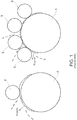
- the system for simulating the contact between wheel and rail 1 according to the invention in particular of a railway vehicle, comprises at least one hollow cylindrical structure 3, also called a roller, having a first diameter D1 and including a rail simulation surface 5 arranged integrally with an inner surface 7 of the hollow cylindrical structure 3.
- the rail simulation surface 5 is preferably made of a metallic material, in particular the metallic material from which rails are usually constructed, for example, steel.
- the system for simulating contact between wheel and rail 1 further comprises at least one wheel 9 having a second diameter D2, smaller than said first diameter D1, which includes a rolling surface 11 placed in contact with the rail simulation surface 5 of the hollow cylindrical structure 3.
- the aforesaid arrangement allows one to avoid that the contaminant substance deposited on the roller by an injection system or manually is flung away by the roller due to centrifugal force.
- the system for simulating the contact between wheel and rail 1 also includes a rotation motor M1 coupled to the cylindrical structure 3 to generate a rotation of said first cylindrical structure 3.
- the drive shaft 10 of the motor M1 is coupled with a respective hole 12 located at the center of the hollow cylindrical structure.
- a plurality of rods, also called spokes, or a flat surface extending from the inner surface 7 of the hollow cylindrical structure 3 to the hole 12, may be used to hold said hole 12 in position.
- a second rotation motor M2 is associated with the wheel 9 to generate a rotation of said wheel 9 and to control the slippage thereof, i.e., the relative speed, with respect to the cylindrical structure 3.
- a first sensor means 13 for torque for example a torque transducer, is placed between the motor M2 and the wheel 9 to allow the adhesion force Fa developed in the contact point between the wheel 9 and the hollow cylindrical structure 3 to be measured.
- a second sensor means 15 for load for example a load cell, is located above the wheel 9 and allows the normal load force Fc acting on the rail simulation surface 5 to be measured.
- the ratio between the adhesion force Fa and the normal load force Fc allows the real wheel-rail adhesion coefficient to be calculated.
- the real wheel-rail adhesion coefficient is the estimated value indicative of the adhesion coefficient value that would occur in a normal condition of use of a railway vehicle.
- the ratio between the adhesion force Fa and the normal load force Fc is calculated by processing means not illustrated in the figures.
- Processing means may mean either a control unit belonging to the system for simulating contact between wheel and rail 1 or a remote processor adapted to receive the data measured by sensor means 13, 15 of the system for simulating the contact between wheel and rail 1, wherein the actual calculation of the real wheel-rail adhesion coefficient is performed.
- the system for simulating the contact between wheel and rail 1 also includes at least one contaminant control system 14, adapted to recreate a variation of the friction condition between the wheel 9 and the rail simulation surface 5.
- the variation of the friction condition may coincide with a decrease in the friction value if the injected contaminant substance is, for example, water, oil or leaves, while it may coincide with an increase in the friction value if the injected contaminant substance is, for example, sand.
- the at least one contaminant control system 14 is placed in the proximity of each wheel 9.
- the contaminant control system 14 comprises a contaminant injection system 14A to uniformly distribute the contaminant along the rail simulation surface 5.
- the centrifugal force generated during rotation of the hollow cylindrical structure 3 facilitates checking the contaminant level.
- the contaminant rather than being flung away from the rotating hollow cylindrical structure 3, is held along the rail simulation surface 5 by such centrifugal force.
- the contaminant control device 14 may further comprise a contaminant removal system 14B, achieved, for example, with a jet of compressed air or a spatula or scraper or an aspirator, adapted to remove the contaminant from the cylindrical structure 3.
- a contaminant removal system 14B achieved, for example, with a jet of compressed air or a spatula or scraper or an aspirator, adapted to remove the contaminant from the cylindrical structure 3.
- the contaminant control system 14 may comprise at least one contaminant sensor means 20 adapted to detect the level of contamination of the system for simulating the contact between wheel and rail 1. In this way, it is possible to establish whether to inject more contaminant, if the contaminant on the hollow cylindrical structure 3 is insufficient; or to stop injecting contaminant, if the contaminant on the cylindrical structure 3 is sufficient; or to remove contaminant, if its quantity on the hollow cylindrical structure 3 is excessive.
- the contaminant sensor means 20 used may, for example, be at least one of either an optical sensor or a conductivity sensor.
- Figure 3 illustrates a second embodiment of a system for simulating the contact between wheel and rail 1.
- the difference with respect to the embodiment illustrated above consists in the fact that the wheels 9 are at least two in number. In the example illustrated in this figure, there are four wheels.
- the four wheels 9 are arranged longitudinally aligned with each other, in contact with the track simulation surface 5, along a plane perpendicular to the rotation axis thereof.
- a third embodiment illustrated in figure 4 the difference with respect to the embodiments illustrated above consists in the fact that there are two hollow cylindrical structures 3, which form a pair of cylindrical structures 3A, 3B, including a first hollow cylindrical structure 3A and a second hollow cylindrical structure 3B.
- the second hollow cylindrical structure 3B is arranged parallel to the first hollow cylindrical structure 3A, along a common rotation axis thereof.
- the wheels are divided in pairs of wheels 9A, 9B, each comprising a first wheel 9A, placed in contact with the rail simulation surface 5 of the first cylindrical structure 3A, and a second wheel 9B, placed in contact with the rail simulation surface 5 of the second cylindrical structure 3B.
- the first and second wheels 9A, 9B are connected to each other by an axle 17.
- the axle 17, and consequently the first and second wheels 9A, 9B, is rotated by means of the rotation motor M2.
- Each hollow cylindrical structure 3A, 3B is rotated independently of the others by means of respective rotation motors M1.
- the pairs of wheels are at least two and are installed on a bogie 19 for a railway vehicle.
- the pairs of wheels are arranged longitudinally aligned with each other along a plane perpendicular to the rotation axis thereof.
- each wheel 9 is kept in contact with the rail simulation surface 5 through a load actuation system not illustrated in the figures, adapted to generate a force Fl to simulate the load generated by the weight of a carriage of a railway vehicle.
- the load actuation system may be achieved through hydraulic or pneumatic springs or actuators.
- the system for simulating the contact between wheel and rail 1 may further include an electromagnetic braking system 22, known as a magnetic shoe or MTB (magnetic track brake) acting directly on the rail simulation surface 5 and positioned between the two wheels.
- an electromagnetic braking system 22 known as a magnetic shoe or MTB (magnetic track brake) acting directly on the rail simulation surface 5 and positioned between the two wheels.
- MTB magnetic track brake
- Such system may optionally be activated to evaluate the impact on the braking force transferred to the hollow cylindrical structure 3 and to evaluate the impact thereof on the rail simulation surface 5.
- At least one rotation motor M1 is coupled on the perimeter of the hollow cylindrical structure 3, for example by means of respective toothed surfaces 60.
- WSP wheel slide protection system
- the system for simulating the contact between wheel and rail 1 comprises a plurality of speed sensor means 70.
- Each speed sensor means 70 is adapted to detect an angular speed of one of said wheels 9.
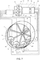
- the system for simulating the contact between wheel and rail 1 also comprises a slide protection system 72 of the wheels 9, WSP, adapted to determine the slide values of the wheels of which the angular speed has been detected.
- the slide protection system 72 of the wheels 9, WSP is also adapted to apply pressure to an air tank 74 adapted to simulate a brake cylinder for each wheel 9 of which the angular speed has been detected.
- the air tank may be a container inside of which a certain amount of air is enclosed.
- the pressure value applied to the air tank 74 is generated as a function of slide values determined by the slide protection system 72, WSP.
- the pressure value may be lower for the air tanks 74 associated with wheels that the WSP has determined to be slipping.
- the system for simulating the contact between wheel and rail 1 comprises a pressure/braking torque conversion system 76 adapted to convert the pressure value applied to the air tank 74 into respective braking torque signals 79 for each wheel, and a plurality of braking means 78, each associated with one of said wheels whose angular speed has been detected.
- Each braking means is adapted to apply to its associated wheel a braking torque corresponding to the braking torque signal 79 received from the pressure/braking torque conversion system 76.
- the pressure/braking torque conversion system 76 may include a plurality of pressure transducers 80, each acting to provide an electrical pressure signal 82, the value of which corresponds to one of the pressure values applied to the air tanks 74 generated by the slide protection system 72.
- the pressure/braking torque conversion system 76 may further include a pressure/force conversion module 84 adapted to convert each electrical pressure signal 82 into an electrical braking force signal 85 and a force/torque conversion module 86 adapted to convert, according to the radius of the wheels, the electrical braking force signals 85 into respective braking torque signals 79 to be supplied to the respective braking means 78.
- FIG. 7 illustrates the case wherein the WSP module is used in a system for simulating the contact between wheel and rail according to the embodiment wherein the wheels 9 are arranged longitudinally aligned to each other along a plane perpendicular to the rotation axis thereof; however, such WSP system may also be used in any of the embodiments described above and shown in the figures, wherein a plurality of wheels are present.
- the structure of the system for simulating the contact between wheel and rail may comprise a simplified structure and comprise at least one hollow cylindrical structure 3 having a first diameter D1 and including a rail simulation surface 5 integrally arranged with an inner surface 7 of said hollow cylindrical structure 3 and at least one wheel 9 having a second diameter D2 smaller than said first diameter D1, and including a rolling surface 11 placed in contact with said rail simulation surface 5 of the hollow cylindrical structure 3.
- said at least one wheel 9 may be a plurality of wheels 9 arranged longitudinally aligned with each other in contact with the rail simulation surface 5 along a plane perpendicular to the rotation axis thereof for simulating a condition of rail cleaning.
- the invention further comprises a method for simulating the contact between wheel and rail 1, in particular of a railway vehicle, comprising the steps of:
- the advantage provided by the invention is therefore to provide a system and a method which allow the condition of contamination of the rail to be simulated by means of a stable contaminant layer for any type of contaminant or simulated speed.
Landscapes
- Engineering & Computer Science (AREA)
- Physics & Mathematics (AREA)
- General Physics & Mathematics (AREA)
- Transportation (AREA)
- Mechanical Engineering (AREA)
- Theoretical Computer Science (AREA)
- Geometry (AREA)
- Computer Hardware Design (AREA)
- General Engineering & Computer Science (AREA)
- Evolutionary Computation (AREA)
- Life Sciences & Earth Sciences (AREA)
- Power Engineering (AREA)
- Sustainable Energy (AREA)
- Sustainable Development (AREA)
- Mathematical Analysis (AREA)
- Mathematical Optimization (AREA)
- Pure & Applied Mathematics (AREA)
- Computational Mathematics (AREA)
- Regulating Braking Force (AREA)
- Electric Propulsion And Braking For Vehicles (AREA)
- Force Measurement Appropriate To Specific Purposes (AREA)
Claims (15)
- System zum Simulieren des Kontakts zwischen Rad und Schiene (1), insbesondere eines Schienenfahrzeugs, mit:- mindestens einer hohlen zylindrischen Struktur (3), die einen ersten Durchmesser (D1) aufweist und eine Schienensimulationsoberfläche (5), die integral mit einer inneren Oberfläche (7) besagter hohlen zylindrischen Struktur (3) angeordnet ist, aufweist;- mindestens einem Rad (9), das einen zweiten Durchmesser (D2) kleiner als besagter erster Durchmesser (D1) aufweist und eine Rolloberfläche (11), die mit besagter Schienensimulationsoberfläche (5) der hohlen zylindrischen Struktur (3) in Kontakt platziert ist, aufweist;- mindestens einem Drehmotor (M1), der mit besagter hohlen zylindrischen Struktur (3) assoziiert ist, zum Erzeugen einer Drehung besagter ersten zylindrischen Struktur (3); dadurch gekennzeichnet, dass das System ferner aufweist:- mindestens einen zweiten Drehmotor (M2), der mit dem mindestens einen Rad (9) assoziiert ist, zum Steuern einer Drehung besagten mindestens einen Rads (9);- mindestens ein Verunreinigungssteuerungssystem (14), das dazu angepasst ist, die Verteilung einer Verunreinigung auf der Schienensimulationsoberfläche (5) zum Erzeugen einer Variation der Reibungsbedingung zwischen dem mindestens einen Rad (9) und der Schienensimulationsoberfläche (5) zu steuern;- mindestens ein erstes Sensormittel (13) für Drehmoment, das dazu angepasst ist, eine Adhäsionskraft (Fa), die an dem Kontaktpunkt zwischen dem mindestens einen Rad (9) und der mindestens einen zylindrischen Struktur (3) entwickelt wird, zu messen;- mindestens ein zweites Sensormittel (15) für Belastung, das dazu angepasst ist, eine Normalbelastungskraft (Fc) auf der Schienensimulationsoberfläche (5) zu messen; und- ein Prozessierungsmittel, das dazu angepasst ist, einen tatsächlichen Rad-Schiene-Adhäsionskoeffizienten durch das Verhältnis zwischen der Adhäsionskraft (Fa) und der Normalbelastungskraft (Fc) zu berechnen.
- System zum Simulieren des Kontakts zwischen Rad und Schiene (1) nach Anspruch 1, bei dem besagtes mindestens eine Rad (9) eine Mehrzahl von Rädern (9) ist; welche besagten Räder (9) longitudinal zueinander ausgerichtet in Kontakt mit der Schienensimulationsoberfläche (5) entlang einer Ebene senkrecht zu der Drehachse davon zum Simulieren einer Bedingung einer Schienenreinigung angeordnet sind.
- System zum Simulieren des Kontakts zwischen Rad und Schiene (1) nach einem der vorhergehenden Ansprüche, bei dem:- besagte mindestens eine hohle zylindrische Struktur (3) zumindest ein Paar zylindrischer Strukturen (3A, 3B) ist, das eine erste hohle zylindrische Struktur (3A) und eine zweite hohle zylindrische Struktur (3B) aufweist; welche zweite hohle zylindrische Struktur (3B) entlang einer gemeinsamen Drehachse davon angeordnet ist;- besagtes mindestens eine Rad (9) zumindest ein Paar von Rädern (9A, 9B) ist, das ein erstes Rad (9A), das in Kontakt mit der Schienensimulationsoberfläche (5) der ersten zylindrischen Struktur (3A) platziert ist, und ein zweites Rad (9B), das in Kontakt mit der Schienensimulationsoberfläche (5) der zweiten zylindrischen Struktur (3B) platziert ist, aufweist; welches erste und welches zweite Rad (9A, 9B) mit einer Achse (17) verbunden sind.
- System zum Simulieren des Kontakts zwischen Rad und Schiene (1) nach Anspruch 3, bei dem die Paare von Rädern mindestens zwei sind und auf einem Fahrwerk (19) für ein Schienenfahrzeug montiert sind; welche besagten Paare von Rädern longitudinal zueinander ausgerichtet entlang einer Ebene senkrecht zu der Drehachse davon angeordnet sind.
- System zum Simulieren des Kontakts zwischen Rad und Schiene (1) nach Anspruch 3 oder 4, bei dem die Räder (9) einer Achse durch einen einzelnen Drehmotor (M2) gesteuert werden.
- System zum Simulieren des Kontakts zwischen Rad und Schiene (1) nach einem der vorhergehenden Ansprüche, bei dem jede hohle zylindrische Struktur (3) unabhängig von der anderen durch einen Drehmotor (M1) gedreht wird.
- System zum Simulieren des Kontakts zwischen Rad und Schiene (1) nach einem der vorhergehenden Ansprüche, bei dem das Verunreinigungssteuerungssystem (14) ein Verunreinigungseingabesystem (14A) zum Verteilen der Verunreinigung entlang der Schienensimulationsoberfläche (5), ein Verunreinigungsentfernungssystem (14B), das dazu angepasst ist, die Verunreinigung von der Schienensimulationsoberfläche (5) zu entfernen, und mindestens ein Verunreinigungsgradsensormittel (20), das dazu angepasst ist, den Verunreinigungsgrad des Systems zum Simulieren des Kontakts zwischen Rad und Schiene (1) zu erfassen, aufweist.
- System zum Simulieren des Kontakts zwischen Rad und Schiene (1) nach einem der vorhergehenden Ansprüche, bei dem das Verunreinigungsgradsensormittel (20) mindestens einer von entweder einem optischen Sensor oder einem Leitfähigkeitssensor ist.
- System zum Simulieren des Kontakts zwischen Rad und Schiene (1) nach einem der vorhergehenden Ansprüche, bei dem jedes Rad (9) durch eine Kraft (Fl), die dazu angepasst ist, eine Belastung, die durch das Gewicht eines Wagens eines Schienenfahrzeugs erzeugt wird, zu simulieren, in Kontakt mit der Schienensimulationsoberfläche (5) gehalten wird.
- System zum Simulieren des Kontakts zwischen Rad und Schiene (1) nach einem der vorhergehenden Ansprüche, bei dem mit dem mindestens einen Rad ein elektromagnetisches Bremssystem (22), das direkt auf die Schienensimulationsoberfläche (5) wirkt, assoziiert ist.
- System zum Simulieren des Kontakts zwischen Rad und Schiene (1) nach Anspruch 10, bei dem das elektromagnetische Bremssystem (22) ein Magnetschuh, MTB, ist.
- System zum Simulieren des Kontakts zwischen Rad und Schiene (1) nach einem der vorhergehenden Ansprüche, bei dem der mindestens eine Drehmotor (M1), der mit besagter hohlen zylindrischen Struktur (3) assoziiert ist, an den Umfang besagter hohlen zylindrischen Struktur (3) gekoppelt ist.
- System zum Simulieren des Kontakts zwischen Rad und Schiene (1) nach einem der vorhergehenden Ansprüche 2 bis 12, mit:- einer Mehrzahl von Geschwindigkeitssensormitteln (70), von denen jedes Geschwindigkeitssensormittel (70) dazu angepasst ist, eine Winkelgeschwindigkeit eines besagter Räder (9) zu erfassen;- einem Gleitschutzsystem (72) der Räder (9), WSP, das dazu angepasst ist, die Gleitwerte der Räder, deren Winkelgeschwindigkeit erfasst worden ist, zu bestimmen und Druck auf einen Lufttank (74), der dazu angepasst ist, einen Bremszylinder zu simulieren, für jedes Rad (9), von dem die Winkelgeschwindigkeit erfasst worden ist, auszuüben, bei dem der Druckwert, der auf den Lufttank (74) ausgeübt wird, als eine Funktion von Gleitwerten, die durch das Gleitschutzsystem (72), WSP, bestimmt werden, erzeugt wird;- einem Druck/Bremsdrehmoment-Umwandlungssystem (76), das dazu angepasst ist, den Druckwert, der in dem Lufttank (74) erfasst wird, in jeweilige Bremsdrehmomentsignale (79) für jedes Rad umzuwandeln;- einer Mehrzahl von Bremsmitteln (78), die jeweils mit einem besagter Räder, von denen die Winkelgeschwindigkeit erfasst worden ist, assoziiert sind; bei denen jedes Bremsmittel dazu angepasst ist, auf sein assoziiertes Rad ein Bremsdrehmoment auszuüben, das dem Bremsdrehmomentsignal (79), das von dem Druck/Bremsdrehmoment-Umwandlungssystem (76) empfangen wird, entspricht.
- System zum Simulieren des Kontakts zwischen Rad und Schiene (1) nach Anspruch 13, bei dem das Druck/Bremsdrehmoment-Umwandlungssystem (76) aufweist:- eine Mehrzahl von Druckwandlern (80), bei denen jeder Druckwandler dazu angepasst ist, ein elektrisches Drucksignal (82) vorzusehen, dessen Wert einem der Druckwerte, die auf die Lufttanks (74) mittels des Gleitschutzsystems (72) ausgeübt werden, entspricht;- ein Druck/Kraft-Umwandlungsmodul (84), das dazu angepasst ist, jedes elektrische Drucksignal (82) in ein elektrisches Bremskraftsignal (85) umzuwandeln;- ein Kraft/Drehmoment-Umwandlungsmodul (86), das dazu angepasst ist, gemäß dem Radius der Räder die elektrischen Bremskraftsignale (85) in jeweilige Bremsdrehmomentsignale (79), die den jeweiligen Bremsmitteln (78) zuzuführen sind, umzuwandeln.
- Verfahren zum Simulieren des Kontakts zwischen Rad und Schiene (1), insbesondere eines Schienenfahrzeugs, mit den Schritten:- Vorsehen zumindest einer hohlen zylindrischen Struktur (3), die einen ersten Durchmesser (D1) aufweist und eine Schienensimulationsoberfläche (5), die integral mit einer inneren Oberfläche (7) besagter hohlen zylindrischen Struktur (3) angeordnet ist, aufweist;- Vorsehen innerhalb besagter ersten hohlen zylindrischen Struktur (3), in Kontakt mit besagter Schienensimulationsoberfläche (5) der hohlen zylindrischen Struktur (3), mindestens eines Rads (9), das einen zweiten Durchmesser (D2) kleiner als besagter erster Durchmesser (D1) aufweist;- Drehen besagter ersten hohlen zylindrischen Struktur (3) mittels zumindest eines ersten Motors (M1); dadurch gekennzeichnet, dass das Verfahren ferner die Schritte:- Drehen des mindestens einen Rads (9) mittels mindestens eines Drehmotors (M2), der mit besagtem mindestens einen Rad (9) assoziiert ist;- Eingeben einer Verunreinigungssubstanz auf zumindest einen Teil besagter Schienensimulationsoberfläche (5) mittels mindestens eines Verunreinigungssteuerungssystems (14);- Messen einer Adhäsionskraft (Fa), die an dem Kontaktpunkt zwischen dem mindestens einen Rad (9) und der mindestens einen zylindrischen Struktur (3) entwickelt wird, mittels zumindest eines ersten Sensormittels (13) für Drehmoment;- Prüfen und Messen einer Normalbelastungskraft (Fc) auf der Schienensimulationsoberfläche (5) mittels mindestens eines zweiten Sensormittels (15) für Belastung; und- Berechnen des tatsächlichen Rad-Schiene-Adhäsionskoeffizienten durch das Verhältnis zwischen der Adhäsionskraft (Fa) und der Normalbelastungskraft (Fc) aufweist.
Applications Claiming Priority (2)
| Application Number | Priority Date | Filing Date | Title |
|---|---|---|---|
| IT102017000035856A IT201700035856A1 (it) | 2017-03-31 | 2017-03-31 | Sistema e procedimento per la simulazione del contatto tra ruota e rotaia per il rilevamento del valore di adesione. |
| PCT/IB2018/052170 WO2018178914A1 (en) | 2017-03-31 | 2018-03-29 | A system and a method for simulating the contact between wheel and rail for detecting the adhesion value |
Publications (2)
| Publication Number | Publication Date |
|---|---|
| EP3601978A1 EP3601978A1 (de) | 2020-02-05 |
| EP3601978B1 true EP3601978B1 (de) | 2021-01-20 |
Family
ID=59683807
Family Applications (1)
| Application Number | Title | Priority Date | Filing Date |
|---|---|---|---|
| EP18719295.0A Active EP3601978B1 (de) | 2017-03-31 | 2018-03-29 | System und verfahren zur simulation des kontaktes zwischen rad und schiene zum nachweis des haftwerts |
Country Status (9)
| Country | Link |
|---|---|
| US (1) | US20200364385A1 (de) |
| EP (1) | EP3601978B1 (de) |
| JP (1) | JP7125945B2 (de) |
| CN (1) | CN110383026B (de) |
| ES (1) | ES2861652T3 (de) |
| HU (1) | HUE053846T2 (de) |
| IT (1) | IT201700035856A1 (de) |
| RU (1) | RU2755527C2 (de) |
| WO (1) | WO2018178914A1 (de) |
Families Citing this family (1)
| Publication number | Priority date | Publication date | Assignee | Title |
|---|---|---|---|---|
| CN115826077A (zh) * | 2022-09-20 | 2023-03-21 | 中车株洲电力机车有限公司 | 一种制动极靴异物检测方法及相关组件 |
Family Cites Families (11)
| Publication number | Priority date | Publication date | Assignee | Title |
|---|---|---|---|---|
| JPS5853736A (ja) * | 1981-09-25 | 1983-03-30 | Nippon Kokan Kk <Nkk> | 転動疲労試験機 |
| DE3604186A1 (de) * | 1986-02-10 | 1987-08-13 | Fraunhofer Ges Forschung | Verfahren und einrichtung zur pruefung von schienenfahrzeugraedern unter betriebsaehnlichen belastungsbedingungen |
| RU2227908C2 (ru) * | 2002-04-10 | 2004-04-27 | Московская железная дорога | Стенд для диагностики колесных пар рельсовых транспортных средств |
| JP4291088B2 (ja) | 2003-08-28 | 2009-07-08 | 財団法人鉄道総合技術研究所 | 摩擦緩和材の収容装置及び摩擦緩和装置 |
| JP4904260B2 (ja) * | 2004-06-17 | 2012-03-28 | エムティーエス システムズ コーポレイション | 多軸ホイール疲労システムのための制御方法 |
| KR100721607B1 (ko) * | 2005-11-22 | 2007-05-23 | 한국철도기술연구원 | 전기적인 공전활주 모의장치 |
| WO2012176359A1 (ja) | 2011-06-23 | 2012-12-27 | 株式会社ブリヂストン | タイヤ試験装置 |
| JP5616931B2 (ja) * | 2012-08-02 | 2014-10-29 | 住友ゴム工業株式会社 | タイヤの台上試験装置及びこれを用いたタイヤ性能試験方法 |
| DE102014106086A1 (de) * | 2014-04-30 | 2015-11-05 | Knorr-Bremse Systeme für Schienenfahrzeuge GmbH | Rollenprüfstand und Betriebsverfahren für einen Rollenprüfstand |
| CN105738127B (zh) * | 2016-02-06 | 2018-02-13 | 北京化工大学 | 一种胎面胶磨耗测试设备及其测试方法 |
| CN106323650A (zh) * | 2016-11-10 | 2017-01-11 | 中国汽车技术研究中心 | 一种轮毂电机车轮总成性能模拟试验台及其使用方法 |
-
2017
- 2017-03-31 IT IT102017000035856A patent/IT201700035856A1/it unknown
-
2018
- 2018-03-29 ES ES18719295T patent/ES2861652T3/es active Active
- 2018-03-29 US US16/496,029 patent/US20200364385A1/en not_active Abandoned
- 2018-03-29 EP EP18719295.0A patent/EP3601978B1/de active Active
- 2018-03-29 CN CN201880012732.9A patent/CN110383026B/zh active Active
- 2018-03-29 WO PCT/IB2018/052170 patent/WO2018178914A1/en not_active Ceased
- 2018-03-29 RU RU2019131110A patent/RU2755527C2/ru active
- 2018-03-29 HU HUE18719295A patent/HUE053846T2/hu unknown
- 2018-03-29 JP JP2019543794A patent/JP7125945B2/ja active Active
Also Published As
| Publication number | Publication date |
|---|---|
| WO2018178914A1 (en) | 2018-10-04 |
| EP3601978A1 (de) | 2020-02-05 |
| ES2861652T3 (es) | 2021-10-06 |
| RU2755527C2 (ru) | 2021-09-16 |
| US20200364385A1 (en) | 2020-11-19 |
| JP2020515821A (ja) | 2020-05-28 |
| CN110383026B (zh) | 2022-10-04 |
| RU2019131110A (ru) | 2021-04-05 |
| JP7125945B2 (ja) | 2022-08-25 |
| IT201700035856A1 (it) | 2018-10-01 |
| CN110383026A (zh) | 2019-10-25 |
| HUE053846T2 (hu) | 2021-07-28 |
| RU2019131110A3 (de) | 2021-06-28 |
Similar Documents
| Publication | Publication Date | Title |
|---|---|---|
| EP3423315B1 (de) | Verfahren zur verbesserung der leistung einer antiblockier- und antischlupfregelung eines fahrzeuges | |
| Matsumoto et al. | Creep force characteristics between rail and wheel on scaled model | |
| EP3309024A1 (de) | Verfahren und system zur bestimmung der reibung zwischen dem boden und einem reifen eines fahrzeuges | |
| US7617721B2 (en) | Apparatus and methods for determining a predicted vehicle braking operation | |
| US8965657B2 (en) | System and method for detecting an on ground condition of an aircraft | |
| EP3403892B1 (de) | Beurteilung der oberflächenbedingungen von start- und landebahnen | |
| EP3601978B1 (de) | System und verfahren zur simulation des kontaktes zwischen rad und schiene zum nachweis des haftwerts | |
| US6112600A (en) | Measuring platform for weight and brake system monitoring | |
| EP2157002B1 (de) | Verfahren zur Bestimmung des Schwimmwinkels eines Kraftfahrzeugs | |
| DE102017207476A1 (de) | Verfahren und Vorrichtung zum Überwachen einer Bremsanlage eines Fahrzeugs | |
| KR20130132818A (ko) | 진단 타이어 시험 방법 | |
| CN105954542A (zh) | 一种全自动汽车车速检测设备 | |
| RU2211891C1 (ru) | Устройство для определения коэффициента сцепления колеса с дорожным покрытием | |
| Erdogan et al. | Adaptive vibration cancellation for tire-road friction coefficient estimation on winter maintenance vehicles | |
| Fichtinger et al. | Pneumatic Tyre Aquaplaning: an Experimental Investigation on Manifestations and Influences of Appearance | |
| EP3256830A2 (de) | Multiplattenvorrichtung und verfahren zur prüfung des bremssystems von landfahrzeugen mit mindestens zwei achsen | |
| CN201993238U (zh) | 车辆制动检测装置 | |
| Galvagno et al. | Experimental device for friction levels identification in airport applications | |
| DE19949705A1 (de) | Verfahren und Einrichtung zum Prüfen der Bremsanlage eines Fahrzeuges | |
| EP2085274B1 (de) | Vorrichtung und Verfahren zur Bestimmung eines prognostizierten Bremsvorgangs | |
| Istiar et al. | Review study of irregularity track monitoring based on inertial measure unit and power spectral density analysis | |
| Senabre et al. | Comparative analysis of various brake testers used in Ministry of Transport facilities, such as: bank of roller testers and dynamometric platform testers | |
| DE102010004501B4 (de) | Verfahren zur Bestimmung des Reibwertes auf der Basis der Erfassung von im schienengebundenen Fahrbetrieb auftretenden Kräften | |
| Lepine et al. | Empirical estimation of heavy goods vehicle tyre wear | |
| Andersson | Road-tire friction estimation for afs vehicle control |
Legal Events
| Date | Code | Title | Description |
|---|---|---|---|
| STAA | Information on the status of an ep patent application or granted ep patent |
Free format text: STATUS: UNKNOWN |
|
| STAA | Information on the status of an ep patent application or granted ep patent |
Free format text: STATUS: THE INTERNATIONAL PUBLICATION HAS BEEN MADE |
|
| PUAI | Public reference made under article 153(3) epc to a published international application that has entered the european phase |
Free format text: ORIGINAL CODE: 0009012 |
|
| STAA | Information on the status of an ep patent application or granted ep patent |
Free format text: STATUS: REQUEST FOR EXAMINATION WAS MADE |
|
| 17P | Request for examination filed |
Effective date: 20191023 |
|
| AK | Designated contracting states |
Kind code of ref document: A1 Designated state(s): AL AT BE BG CH CY CZ DE DK EE ES FI FR GB GR HR HU IE IS IT LI LT LU LV MC MK MT NL NO PL PT RO RS SE SI SK SM TR |
|
| AX | Request for extension of the european patent |
Extension state: BA ME |
|
| DAV | Request for validation of the european patent (deleted) | ||
| DAX | Request for extension of the european patent (deleted) | ||
| REG | Reference to a national code |
Ref country code: DE Ref legal event code: R079 Ref document number: 602018012083 Country of ref document: DE Free format text: PREVIOUS MAIN CLASS: G01L0005280000 Ipc: B60T0008172000 |
|
| GRAP | Despatch of communication of intention to grant a patent |
Free format text: ORIGINAL CODE: EPIDOSNIGR1 |
|
| STAA | Information on the status of an ep patent application or granted ep patent |
Free format text: STATUS: GRANT OF PATENT IS INTENDED |
|
| RIC1 | Information provided on ipc code assigned before grant |
Ipc: G01M 17/08 20060101ALI20200728BHEP Ipc: B60T 13/66 20060101ALI20200728BHEP Ipc: B60T 8/172 20060101AFI20200728BHEP Ipc: B60T 17/22 20060101ALI20200728BHEP Ipc: B60T 8/17 20060101ALI20200728BHEP Ipc: G01L 5/28 20060101ALI20200728BHEP Ipc: B60L 3/10 20060101ALI20200728BHEP |
|
| INTG | Intention to grant announced |
Effective date: 20200814 |
|
| GRAS | Grant fee paid |
Free format text: ORIGINAL CODE: EPIDOSNIGR3 |
|
| GRAA | (expected) grant |
Free format text: ORIGINAL CODE: 0009210 |
|
| STAA | Information on the status of an ep patent application or granted ep patent |
Free format text: STATUS: THE PATENT HAS BEEN GRANTED |
|
| AK | Designated contracting states |
Kind code of ref document: B1 Designated state(s): AL AT BE BG CH CY CZ DE DK EE ES FI FR GB GR HR HU IE IS IT LI LT LU LV MC MK MT NL NO PL PT RO RS SE SI SK SM TR |
|
| REG | Reference to a national code |
Ref country code: GB Ref legal event code: FG4D |
|
| REG | Reference to a national code |
Ref country code: CH Ref legal event code: EP |
|
| REG | Reference to a national code |
Ref country code: AT Ref legal event code: REF Ref document number: 1356128 Country of ref document: AT Kind code of ref document: T Effective date: 20210215 Ref country code: CH Ref legal event code: PK Free format text: BERICHTIGUNGEN |
|
| REG | Reference to a national code |
Ref country code: IE Ref legal event code: FG4D |
|
| REG | Reference to a national code |
Ref country code: DE Ref legal event code: R096 Ref document number: 602018012083 Country of ref document: DE |
|
| REG | Reference to a national code |
Ref country code: DE Ref legal event code: R083 Ref document number: 602018012083 Country of ref document: DE |
|
| RIN2 | Information on inventor provided after grant (corrected) |
Inventor name: FREA, MATTEO Inventor name: IMBERT, LUC |
|
| REG | Reference to a national code |
Ref country code: NL Ref legal event code: MP Effective date: 20210120 |
|
| REG | Reference to a national code |
Ref country code: LT Ref legal event code: MG9D |
|
| REG | Reference to a national code |
Ref country code: AT Ref legal event code: MK05 Ref document number: 1356128 Country of ref document: AT Kind code of ref document: T Effective date: 20210120 |
|
| REG | Reference to a national code |
Ref country code: HU Ref legal event code: AG4A Ref document number: E053846 Country of ref document: HU |
|
| PG25 | Lapsed in a contracting state [announced via postgrant information from national office to epo] |
Ref country code: FI Free format text: LAPSE BECAUSE OF FAILURE TO SUBMIT A TRANSLATION OF THE DESCRIPTION OR TO PAY THE FEE WITHIN THE PRESCRIBED TIME-LIMIT Effective date: 20210120 Ref country code: GR Free format text: LAPSE BECAUSE OF FAILURE TO SUBMIT A TRANSLATION OF THE DESCRIPTION OR TO PAY THE FEE WITHIN THE PRESCRIBED TIME-LIMIT Effective date: 20210421 Ref country code: HR Free format text: LAPSE BECAUSE OF FAILURE TO SUBMIT A TRANSLATION OF THE DESCRIPTION OR TO PAY THE FEE WITHIN THE PRESCRIBED TIME-LIMIT Effective date: 20210120 Ref country code: BG Free format text: LAPSE BECAUSE OF FAILURE TO SUBMIT A TRANSLATION OF THE DESCRIPTION OR TO PAY THE FEE WITHIN THE PRESCRIBED TIME-LIMIT Effective date: 20210420 Ref country code: LT Free format text: LAPSE BECAUSE OF FAILURE TO SUBMIT A TRANSLATION OF THE DESCRIPTION OR TO PAY THE FEE WITHIN THE PRESCRIBED TIME-LIMIT Effective date: 20210120 Ref country code: PT Free format text: LAPSE BECAUSE OF FAILURE TO SUBMIT A TRANSLATION OF THE DESCRIPTION OR TO PAY THE FEE WITHIN THE PRESCRIBED TIME-LIMIT Effective date: 20210520 Ref country code: NO Free format text: LAPSE BECAUSE OF FAILURE TO SUBMIT A TRANSLATION OF THE DESCRIPTION OR TO PAY THE FEE WITHIN THE PRESCRIBED TIME-LIMIT Effective date: 20210420 |
|
| PG25 | Lapsed in a contracting state [announced via postgrant information from national office to epo] |
Ref country code: SE Free format text: LAPSE BECAUSE OF FAILURE TO SUBMIT A TRANSLATION OF THE DESCRIPTION OR TO PAY THE FEE WITHIN THE PRESCRIBED TIME-LIMIT Effective date: 20210120 Ref country code: AT Free format text: LAPSE BECAUSE OF FAILURE TO SUBMIT A TRANSLATION OF THE DESCRIPTION OR TO PAY THE FEE WITHIN THE PRESCRIBED TIME-LIMIT Effective date: 20210120 Ref country code: LV Free format text: LAPSE BECAUSE OF FAILURE TO SUBMIT A TRANSLATION OF THE DESCRIPTION OR TO PAY THE FEE WITHIN THE PRESCRIBED TIME-LIMIT Effective date: 20210120 Ref country code: RS Free format text: LAPSE BECAUSE OF FAILURE TO SUBMIT A TRANSLATION OF THE DESCRIPTION OR TO PAY THE FEE WITHIN THE PRESCRIBED TIME-LIMIT Effective date: 20210120 Ref country code: PL Free format text: LAPSE BECAUSE OF FAILURE TO SUBMIT A TRANSLATION OF THE DESCRIPTION OR TO PAY THE FEE WITHIN THE PRESCRIBED TIME-LIMIT Effective date: 20210120 |
|
| PG25 | Lapsed in a contracting state [announced via postgrant information from national office to epo] |
Ref country code: IS Free format text: LAPSE BECAUSE OF FAILURE TO SUBMIT A TRANSLATION OF THE DESCRIPTION OR TO PAY THE FEE WITHIN THE PRESCRIBED TIME-LIMIT Effective date: 20210520 |
|
| REG | Reference to a national code |
Ref country code: ES Ref legal event code: FG2A Ref document number: 2861652 Country of ref document: ES Kind code of ref document: T3 Effective date: 20211006 |
|
| REG | Reference to a national code |
Ref country code: DE Ref legal event code: R097 Ref document number: 602018012083 Country of ref document: DE |
|
| PG25 | Lapsed in a contracting state [announced via postgrant information from national office to epo] |
Ref country code: SM Free format text: LAPSE BECAUSE OF FAILURE TO SUBMIT A TRANSLATION OF THE DESCRIPTION OR TO PAY THE FEE WITHIN THE PRESCRIBED TIME-LIMIT Effective date: 20210120 Ref country code: CZ Free format text: LAPSE BECAUSE OF FAILURE TO SUBMIT A TRANSLATION OF THE DESCRIPTION OR TO PAY THE FEE WITHIN THE PRESCRIBED TIME-LIMIT Effective date: 20210120 Ref country code: EE Free format text: LAPSE BECAUSE OF FAILURE TO SUBMIT A TRANSLATION OF THE DESCRIPTION OR TO PAY THE FEE WITHIN THE PRESCRIBED TIME-LIMIT Effective date: 20210120 Ref country code: MC Free format text: LAPSE BECAUSE OF FAILURE TO SUBMIT A TRANSLATION OF THE DESCRIPTION OR TO PAY THE FEE WITHIN THE PRESCRIBED TIME-LIMIT Effective date: 20210120 |
|
| REG | Reference to a national code |
Ref country code: CH Ref legal event code: PL |
|
| PLBE | No opposition filed within time limit |
Free format text: ORIGINAL CODE: 0009261 |
|
| STAA | Information on the status of an ep patent application or granted ep patent |
Free format text: STATUS: NO OPPOSITION FILED WITHIN TIME LIMIT |
|
| PG25 | Lapsed in a contracting state [announced via postgrant information from national office to epo] |
Ref country code: DK Free format text: LAPSE BECAUSE OF FAILURE TO SUBMIT A TRANSLATION OF THE DESCRIPTION OR TO PAY THE FEE WITHIN THE PRESCRIBED TIME-LIMIT Effective date: 20210120 Ref country code: SK Free format text: LAPSE BECAUSE OF FAILURE TO SUBMIT A TRANSLATION OF THE DESCRIPTION OR TO PAY THE FEE WITHIN THE PRESCRIBED TIME-LIMIT Effective date: 20210120 Ref country code: RO Free format text: LAPSE BECAUSE OF FAILURE TO SUBMIT A TRANSLATION OF THE DESCRIPTION OR TO PAY THE FEE WITHIN THE PRESCRIBED TIME-LIMIT Effective date: 20210120 |
|
| REG | Reference to a national code |
Ref country code: BE Ref legal event code: MM Effective date: 20210331 |
|
| 26N | No opposition filed |
Effective date: 20211021 |
|
| PG25 | Lapsed in a contracting state [announced via postgrant information from national office to epo] |
Ref country code: CH Free format text: LAPSE BECAUSE OF NON-PAYMENT OF DUE FEES Effective date: 20210331 Ref country code: AL Free format text: LAPSE BECAUSE OF FAILURE TO SUBMIT A TRANSLATION OF THE DESCRIPTION OR TO PAY THE FEE WITHIN THE PRESCRIBED TIME-LIMIT Effective date: 20210120 Ref country code: LI Free format text: LAPSE BECAUSE OF NON-PAYMENT OF DUE FEES Effective date: 20210331 Ref country code: LU Free format text: LAPSE BECAUSE OF NON-PAYMENT OF DUE FEES Effective date: 20210329 Ref country code: IE Free format text: LAPSE BECAUSE OF NON-PAYMENT OF DUE FEES Effective date: 20210329 |
|
| PG25 | Lapsed in a contracting state [announced via postgrant information from national office to epo] |
Ref country code: SI Free format text: LAPSE BECAUSE OF FAILURE TO SUBMIT A TRANSLATION OF THE DESCRIPTION OR TO PAY THE FEE WITHIN THE PRESCRIBED TIME-LIMIT Effective date: 20210120 |
|
| PG25 | Lapsed in a contracting state [announced via postgrant information from national office to epo] |
Ref country code: IS Free format text: LAPSE BECAUSE OF FAILURE TO SUBMIT A TRANSLATION OF THE DESCRIPTION OR TO PAY THE FEE WITHIN THE PRESCRIBED TIME-LIMIT Effective date: 20210520 |
|
| PG25 | Lapsed in a contracting state [announced via postgrant information from national office to epo] |
Ref country code: BE Free format text: LAPSE BECAUSE OF NON-PAYMENT OF DUE FEES Effective date: 20210331 |
|
| PG25 | Lapsed in a contracting state [announced via postgrant information from national office to epo] |
Ref country code: NL Free format text: LAPSE BECAUSE OF NON-PAYMENT OF DUE FEES Effective date: 20210120 Ref country code: CY Free format text: LAPSE BECAUSE OF FAILURE TO SUBMIT A TRANSLATION OF THE DESCRIPTION OR TO PAY THE FEE WITHIN THE PRESCRIBED TIME-LIMIT Effective date: 20210120 |
|
| P01 | Opt-out of the competence of the unified patent court (upc) registered |
Effective date: 20230530 |
|
| PG25 | Lapsed in a contracting state [announced via postgrant information from national office to epo] |
Ref country code: MK Free format text: LAPSE BECAUSE OF FAILURE TO SUBMIT A TRANSLATION OF THE DESCRIPTION OR TO PAY THE FEE WITHIN THE PRESCRIBED TIME-LIMIT Effective date: 20210120 |
|
| PG25 | Lapsed in a contracting state [announced via postgrant information from national office to epo] |
Ref country code: MT Free format text: LAPSE BECAUSE OF FAILURE TO SUBMIT A TRANSLATION OF THE DESCRIPTION OR TO PAY THE FEE WITHIN THE PRESCRIBED TIME-LIMIT Effective date: 20210120 |
|
| PGFP | Annual fee paid to national office [announced via postgrant information from national office to epo] |
Ref country code: ES Payment date: 20250408 Year of fee payment: 8 |
|
| PG25 | Lapsed in a contracting state [announced via postgrant information from national office to epo] |
Ref country code: TR Free format text: LAPSE BECAUSE OF FAILURE TO SUBMIT A TRANSLATION OF THE DESCRIPTION OR TO PAY THE FEE WITHIN THE PRESCRIBED TIME-LIMIT Effective date: 20210120 |
|
| PGFP | Annual fee paid to national office [announced via postgrant information from national office to epo] |
Ref country code: GB Payment date: 20260316 Year of fee payment: 9 |
|
| PGFP | Annual fee paid to national office [announced via postgrant information from national office to epo] |
Ref country code: DE Payment date: 20260217 Year of fee payment: 9 |
|
| PGFP | Annual fee paid to national office [announced via postgrant information from national office to epo] |
Ref country code: IT Payment date: 20260216 Year of fee payment: 9 |
|
| PGFP | Annual fee paid to national office [announced via postgrant information from national office to epo] |
Ref country code: HU Payment date: 20260224 Year of fee payment: 9 |
|
| PGFP | Annual fee paid to national office [announced via postgrant information from national office to epo] |
Ref country code: FR Payment date: 20260312 Year of fee payment: 9 |