EP3601829B1 - Clutch, in particular clutch for motorcycles, and related mounting method - Google Patents
Clutch, in particular clutch for motorcycles, and related mounting method Download PDFInfo
- Publication number
- EP3601829B1 EP3601829B1 EP18713157.8A EP18713157A EP3601829B1 EP 3601829 B1 EP3601829 B1 EP 3601829B1 EP 18713157 A EP18713157 A EP 18713157A EP 3601829 B1 EP3601829 B1 EP 3601829B1
- Authority
- EP
- European Patent Office
- Prior art keywords
- hub
- clutch
- discs
- movable
- sliding
- Prior art date
- Legal status (The legal status is an assumption and is not a legal conclusion. Google has not performed a legal analysis and makes no representation as to the accuracy of the status listed.)
- Active
Links
Images




Classifications
-
- F—MECHANICAL ENGINEERING; LIGHTING; HEATING; WEAPONS; BLASTING
- F16—ENGINEERING ELEMENTS AND UNITS; GENERAL MEASURES FOR PRODUCING AND MAINTAINING EFFECTIVE FUNCTIONING OF MACHINES OR INSTALLATIONS; THERMAL INSULATION IN GENERAL
- F16D—COUPLINGS FOR TRANSMITTING ROTATION; CLUTCHES; BRAKES
- F16D13/00—Friction clutches
- F16D13/22—Friction clutches with axially-movable clutching members
- F16D13/38—Friction clutches with axially-movable clutching members with flat clutching surfaces, e.g. discs
- F16D13/52—Clutches with multiple lamellae ; Clutches in which three or more axially moveable members are fixed alternately to the shafts to be coupled and are pressed from one side towards an axially-located member
-
- F—MECHANICAL ENGINEERING; LIGHTING; HEATING; WEAPONS; BLASTING
- F16—ENGINEERING ELEMENTS AND UNITS; GENERAL MEASURES FOR PRODUCING AND MAINTAINING EFFECTIVE FUNCTIONING OF MACHINES OR INSTALLATIONS; THERMAL INSULATION IN GENERAL
- F16D—COUPLINGS FOR TRANSMITTING ROTATION; CLUTCHES; BRAKES
- F16D13/00—Friction clutches
- F16D13/22—Friction clutches with axially-movable clutching members
- F16D13/38—Friction clutches with axially-movable clutching members with flat clutching surfaces, e.g. discs
- F16D13/52—Clutches with multiple lamellae ; Clutches in which three or more axially moveable members are fixed alternately to the shafts to be coupled and are pressed from one side towards an axially-located member
- F16D13/54—Clutches with multiple lamellae ; Clutches in which three or more axially moveable members are fixed alternately to the shafts to be coupled and are pressed from one side towards an axially-located member with means for increasing the effective force between the actuating sleeve or equivalent member and the pressure member
- F16D13/56—Clutches with multiple lamellae ; Clutches in which three or more axially moveable members are fixed alternately to the shafts to be coupled and are pressed from one side towards an axially-located member with means for increasing the effective force between the actuating sleeve or equivalent member and the pressure member in which the clutching pressure is produced by springs only
-
- F—MECHANICAL ENGINEERING; LIGHTING; HEATING; WEAPONS; BLASTING
- F16—ENGINEERING ELEMENTS AND UNITS; GENERAL MEASURES FOR PRODUCING AND MAINTAINING EFFECTIVE FUNCTIONING OF MACHINES OR INSTALLATIONS; THERMAL INSULATION IN GENERAL
- F16D—COUPLINGS FOR TRANSMITTING ROTATION; CLUTCHES; BRAKES
- F16D25/00—Fluid-actuated clutches
- F16D25/06—Fluid-actuated clutches in which the fluid actuates a piston incorporated in, i.e. rotating with the clutch
- F16D25/062—Fluid-actuated clutches in which the fluid actuates a piston incorporated in, i.e. rotating with the clutch the clutch having friction surfaces
- F16D25/063—Fluid-actuated clutches in which the fluid actuates a piston incorporated in, i.e. rotating with the clutch the clutch having friction surfaces with clutch members exclusively moving axially
- F16D25/0635—Fluid-actuated clutches in which the fluid actuates a piston incorporated in, i.e. rotating with the clutch the clutch having friction surfaces with clutch members exclusively moving axially with flat friction surfaces, e.g. discs
- F16D25/0638—Fluid-actuated clutches in which the fluid actuates a piston incorporated in, i.e. rotating with the clutch the clutch having friction surfaces with clutch members exclusively moving axially with flat friction surfaces, e.g. discs with more than two discs, e.g. multiple lamellae
-
- B—PERFORMING OPERATIONS; TRANSPORTING
- B60—VEHICLES IN GENERAL
- B60Y—INDEXING SCHEME RELATING TO ASPECTS CROSS-CUTTING VEHICLE TECHNOLOGY
- B60Y2200/00—Type of vehicle
- B60Y2200/10—Road Vehicles
- B60Y2200/12—Motorcycles, Trikes; Quads; Scooters
-
- F—MECHANICAL ENGINEERING; LIGHTING; HEATING; WEAPONS; BLASTING
- F16—ENGINEERING ELEMENTS AND UNITS; GENERAL MEASURES FOR PRODUCING AND MAINTAINING EFFECTIVE FUNCTIONING OF MACHINES OR INSTALLATIONS; THERMAL INSULATION IN GENERAL
- F16D—COUPLINGS FOR TRANSMITTING ROTATION; CLUTCHES; BRAKES
- F16D13/00—Friction clutches
- F16D13/58—Details
- F16D13/60—Clutching elements
- F16D13/64—Clutch-plates; Clutch-lamellae
- F16D13/644—Hub construction
-
- F—MECHANICAL ENGINEERING; LIGHTING; HEATING; WEAPONS; BLASTING
- F16—ENGINEERING ELEMENTS AND UNITS; GENERAL MEASURES FOR PRODUCING AND MAINTAINING EFFECTIVE FUNCTIONING OF MACHINES OR INSTALLATIONS; THERMAL INSULATION IN GENERAL
- F16D—COUPLINGS FOR TRANSMITTING ROTATION; CLUTCHES; BRAKES
- F16D13/00—Friction clutches
- F16D13/58—Details
- F16D13/60—Clutching elements
- F16D13/64—Clutch-plates; Clutch-lamellae
- F16D13/648—Clutch-plates; Clutch-lamellae for clutches with multiple lamellae
-
- F—MECHANICAL ENGINEERING; LIGHTING; HEATING; WEAPONS; BLASTING
- F16—ENGINEERING ELEMENTS AND UNITS; GENERAL MEASURES FOR PRODUCING AND MAINTAINING EFFECTIVE FUNCTIONING OF MACHINES OR INSTALLATIONS; THERMAL INSULATION IN GENERAL
- F16D—COUPLINGS FOR TRANSMITTING ROTATION; CLUTCHES; BRAKES
- F16D13/00—Friction clutches
- F16D13/22—Friction clutches with axially-movable clutching members
- F16D13/38—Friction clutches with axially-movable clutching members with flat clutching surfaces, e.g. discs
- F16D13/52—Clutches with multiple lamellae ; Clutches in which three or more axially moveable members are fixed alternately to the shafts to be coupled and are pressed from one side towards an axially-located member
- F16D13/54—Clutches with multiple lamellae ; Clutches in which three or more axially moveable members are fixed alternately to the shafts to be coupled and are pressed from one side towards an axially-located member with means for increasing the effective force between the actuating sleeve or equivalent member and the pressure member
- F16D13/56—Clutches with multiple lamellae ; Clutches in which three or more axially moveable members are fixed alternately to the shafts to be coupled and are pressed from one side towards an axially-located member with means for increasing the effective force between the actuating sleeve or equivalent member and the pressure member in which the clutching pressure is produced by springs only
- F16D2013/565—Clutches with multiple lamellae ; Clutches in which three or more axially moveable members are fixed alternately to the shafts to be coupled and are pressed from one side towards an axially-located member with means for increasing the effective force between the actuating sleeve or equivalent member and the pressure member in which the clutching pressure is produced by springs only with means for releasing the clutch pressure in case of back torque
-
- F—MECHANICAL ENGINEERING; LIGHTING; HEATING; WEAPONS; BLASTING
- F16—ENGINEERING ELEMENTS AND UNITS; GENERAL MEASURES FOR PRODUCING AND MAINTAINING EFFECTIVE FUNCTIONING OF MACHINES OR INSTALLATIONS; THERMAL INSULATION IN GENERAL
- F16D—COUPLINGS FOR TRANSMITTING ROTATION; CLUTCHES; BRAKES
- F16D2300/00—Special features for couplings or clutches
- F16D2300/12—Mounting or assembling
Definitions
- the present invention relates to a clutch, in particular a pre-assembled clutch, and to a method for mounting a clutch.
- the invention relates to a clutch comprising a fixed hub and a moveable hub, between which a plurality of clutch discs is interposed, which allow transmitting a torque when they are axially pushed towards each other.
- the invention relates to clutches for commanding the engagement of a rotary movement between rotating shafts, in particular in land vehicles and more particularly in motorcycles.
- clutch a mechanical element for connecting two shafts with each other in rotary motion in a controlled manner.
- Known clutches use a plurality of circular-crown plates or discs called “driving” or “driven” discs according to their function.
- the driving discs are constrained to a shaft connected to an engine, whereas the driven discs are constrained to a driven shaft of a user transmission.
- Document EP2827016 (A1 ) relates to a power transmitting apparatus which can transmit a torque necessary for performing the pushing start of engine.
- Document EP2778457 (A1 ) relates to a power transmitting apparatus comprising a clutch housing rotatable together with an input member connected to an engine and mounted thereon a plurality of driving-side clutch discs; a clutch member connected to an output member; a plurality of driven-side clutch discs arranged between the driving-side clutch discs alternately therewith; a pressure member for forcing the driving-side clutch discs and the driven-side cutch discs to be press-contacted each other and to release the press-contacting force acting on them in accordance with approach or separation of the pressure member relative to the clutch member; and a kick-starter means.
- Document JPS60184719 (A ) relates to a clutch with a two-stage buffering.
- Document EP2921735 (A1 ) relates to a multi-plate friction clutch including a clutch outer, a clutch centre, clutch plates, and a pressure plate.
- Document US2009071792 (A1 ) relates to a clutch housing rotatable together with an input member and supporting a plurality of driving clutch plates; a pressure member can be mounted on the clutch member so as to be axially movable therealong so as to accommodate pressure-contact and release of the driving clutch plates and the driven clutch plates; back-torque limiting cams can be configured to release the connection between the driving clutch plates and the driven clutch plates.
- Document EP2930387 (A1 ) relates to a clutch apparatus in which an opening is provided on a fixed cam member fixed to an output power shaft so as to form a cam mechanism together with a movable cam member.
- Document JPH08145074 (A ) relates to a clutch for assembly on a transmission input shaft, ensuring a desired fastening torque of a hub fastening bolt or a nut.
- Document EP1058018 (A2 ) to Adler S.p.A. relates to a clutch comprising a fixed hub, a movable hub, a plurality of discs and a pressure plate that, moving in an axial direction, allows engagement and disengagement of the clutch.
- An object of the present invention is to solve some prior art problems.
- a particular object of the present invention is to provide a clutch whose components have an optimized operation, so as to reduce the number and complexity thereof.
- a further particular object of the present invention is to provide a clutch whose components are rationally assemblable with each other, thus simplifying the installation thereof.
- a solution idea underlying the present invention is to provide a clutch comprising: a fixed hub with a central coupling hole configured for coupling with a rotating shaft; a moveable hub configured for being mounted along an axial direction onto the fixed hub; a plurality of discs configured for being interposed between the fixed hub and the moveable hub.
- the fixed hub and the moveable hub are shaped so as to rotate jointly with each other and so as to axially slide with each other, getting farther or closer such that the fixed hub and the moveable hub exert a variable axial load onto the plurality of discs, thereby transmitting a torque.
- the moveable hub of the clutch comprises a central access hole configured for allowing access to the central coupling hole of the fixed hub, passing internally through the plurality of discs interposed, so as to operate locking means and to provide coupling of the clutch with the rotating shaft.
- the clutch structure comprising a fixed hub and a moveable hub thus configured is advantageous in terms of assembly, since it has a more rational structure that does not need a pressure plate separated from the moveable hub.
- the central access hole simplifies the installation and mounting of the clutch, thus allowing locking means, such as a nut, to reach and lock the central coupling hole of the fixed hub on the rotating shaft.
- the clutch according to the present invention can be pre-assembled and moreover allows reducing the number and complexity of the constitutive elements, to the advantage of an optimal operation and a more simplified maintenance for the vehicle on which the clutch is installed.
- a method for mounting a clutch comprises: providing a fixed hub comprising a central coupling hole; providing a moveable hub comprising a central access hole; providing a plurality of discs, in particular mounted on the moveable hub; providing the moveable hub mounted along an axial direction on the fixed hub, wherein the discs result interposed between the fixed hub and the moveable hub, and wherein the fixed hub and the moveable hub are shaped so as to rotate jointly with each other and so as to axially slide with each other, getting farther or closer so that the fixed hub and the moveable hub exert a variable axial load onto the plurality of discs, thereby transmitting a torque; coupling the central coupling hole with a rotating shaft; access the central coupling hole, through the central access hole and internally through the plurality of interposed discs; operating locking means so as to constrain the central coupling hole onto the rotating shaft.
- the method for mounting a clutch provides performing the mounting according to the aspects and details of the clutch according to the present invention.
- the clutch 100 is of the two-piece type, comprising a fixed hub and a moveable hub, without a separated pressure plate acting onto the moveable hub.
- the clutch 100 is used to command the engagement of a rotary movement between an engine shaft and a primary gear fitted on a clutch housing in a vehicle, in particular in a motorcycle.
- FIG. 2 shows an exploded view of the clutch 100, wherein the components are individually identifiable.
- the clutch 100 comprises a fixed hub 101, in particular configured for being coupled with a rotating shaft of the vehicle on which the clutch is installed.
- the clutch 100 then comprises a moveable hub 102, configured for being axially mounted on the fixed hub 101.
- the clutch 100 comprises a plurality of discs 103, which are interposed between the fixed hub 101 and the moveable hub 102.
- the discs 103 comprise a plurality of clutch discs 201 or driving discs, in particular coated discs, which comprise protruding elements configured for coupling with a clutch housing (not shown), which is in turn preferably connected to a driving shaft of the vehicle.
- the discs 103 then comprise a plurality of driven discs 202, which comprise an internal toothing that is configured for coupling with the moveable hub 102, and which are arranged alternatively with respect to the clutch discs 201.
- the discs 103 comprise a turned driving disc, a cup spring and a spacer ring positioned proximally to the flange of the movable hub 102.
- the fixed hub 101 and the moveable hub 102 are shaped so as to rotate jointly with each other when they are axially mounted; in this way, the fixed hub 101 and the moveable hub 102 are adapted to receive a torque.
- the fixed hub 101 and the moveable hub 102 are shaped so as to axially slide with each other, getting farther or closer such as to reduce or increase the axial force intensity on the discs 103.
- the fixed hub 101 and the moveable hub 102 exert a variable axial load on the discs 103, so that when the discs 103 are compressed with each other by the axial load, the clutch 100 allows transmitting a torque between the housing and the rotating shaft of the engine; on the other side, when the axial load decreases and the discs 103 are free to slide with each other, since the fixed hub 101 and the moveable hub 102 are sufficiently distanced, the clutch results disengaged, substantially without any transmitted torque.
- the fixed hub 101 and the moveable hub 102 are configured for getting closer to each other when they are subjected to a driving torque, namely a torque provided by the engine of the vehicle, and are also configured for being distanced from each other when they are subjected to a motoring torque, i.e. a torque contrary to the driving torque provided by the engine of the vehicle.
- a driving torque namely a torque provided by the engine of the vehicle
- a motoring torque i.e. a torque contrary to the driving torque provided by the engine of the vehicle.
- the clutch 100 further comprises a plurality of closing springs 104, preferably with respective spring spacers.
- Said closing springs 104 are configured for applying a closing axial load acting between the movable hub 102 and the fixed hub 101, so as to transmit the torque through the clutch discs.
- the sliding elements are configured for facilitating said closure, by getting the movable hub close to the fixed hub, so as to allow the use of less stiff springs for transmitting a same torque value, to the advantage of a greater ease of clutch command.
- the clutch 100 further comprises an annular retaining element 105 for the springs 104, which is retained by suitable fixing means such as screws, preferably fixed to the fixed hub 101 as it will be further described.
- suitable fixing means such as screws
- the retaining element 105 could be semi-annular or of other suitable shapes.
- the clutch 100 comprises a pusher 106 that is configured for commanding disengagement of the clutch 100 by getting the movable hub 102 farther from the fixed hub 101.
- the pusher 106 is retained in a suitable seat provided on the moveable hub 102 by suitable retaining means, such as a Seeger ring.
- the pusher 106 comprises a rolling element, such as a roller bearing.
- the clutch 100 is a multi-plate one, wherein the movable hub 102 comprises a flange having a free external face, namely not internally engaged in the coupling with the fixed hub 101.
- the flange of the movable hub 102 performs the pressure plate function.
- the movable hub 102 further comprises a drawing element provided with grooves, in which the teeth of the driven discs engage, as it will be further described.
- the fixed hub 101 of the clutch 100 is instead constrained to a rotating shaft, preferably to the primary shaft of the gearbox.
- the closing springs 104 provide a force that gets the fixed hub 101 and the moveable hub 102 axially closer to each other, thus closing the discs 103.
- the closing springs 104 have a suitable spring constant that can confer a lever command that is light and smooth.
- the direction of the helix of the sliding elements is such that, by accelerating, the movable hub 102 and the fixed hub 101 tend to "close” with respect to each other, thus increasing the axial load acting onto the pack of the discs 103, which is added to the force of the springs 104.
- the direction of the helix of the sliding elements is such that the movable hub 101 and the fixed hub 102 tend to "open” with respect to each other, counteracting the force of the springs 104 and obtaining the effect of reducing the axial load acting onto the discs, in a completely automatic way and with no need of "user operation".
- the slope of the sliding elements is thus a calibration element for the system: the more inclined the grooves, the greater the influence of the torque on the load applied onto the discs 103.
- the clutch 100 provides a torque enthralling effect, in addition to a slipper clutch function with back-torque limiter.
- the torque enthralling effect allows reducing (in general more than halve) the axial load that the springs 104 must provide, drastically reducing the effort required at the lever to command the clutch, thus making the driving/ riding more comfortable.
- Figure 3 shows an exploded view of the fixed hub 101, of the movable hub 102 and of the pusher 106.
- the fixed hub 101 comprises a central coupling hole 301 that is shaped so as to provide a coupling with a rotating shaft of the vehicle.
- the movable hub 102 comprises a central access hole 302, in particular made on the flange of the movable hub 102.
- Said central access hole 302 allows access to the central coupling hole 301 once the clutch has been assembled.
- the central access hole 302 allows accessing the central coupling hole 301 by passing internally through the discs 103 interposed (not visible in Figure 3 ) and unimpeded by the further elements of the fixed hub 101 or of the movable hub 102.
- the locking means comprise a nut, introduced during mounting by passing through the central access hole 302.
- the nut is configured for fixing the central coupling hole 301 by threading directly on a threaded end of a rotating shaft, of the engine of the concerned vehicle.
- a clip or elastic-ring locking system could be provided, which could be already arranged inside the pre-assembled clutch and simply be operated for locking, through the access provided by the central access hole 302.
- This variant would be suitable for low loads, where no stresses occur, which may compromise the coupling on the rotating shaft.
- the fixed hub 101 preferably comprises first sliding elements 303, configured for interacting with respective second sliding elements (not visible) inside the movable hub 102, to define sliding surfaces according to a helix that imposes a spacing movement according to a predetermined law between the movable hub 102 and the fixed hub 101, according to what has already been described.
- the particular structure of the fixed hub 101 comprising the first sliding elements 303 separated from each other allows a better lubricant flow directly on the drawing zone engaged by the clutch discs 103.
- Figure 4 shows a top view of the fixed hub 101, in which the first sliding elements 303 are better visible.
- the first sliding elements 303 comprise respective first sliding surfaces 403 and 403b opposite each other, which are sloped according to a helix. Each of the sliding surfaces 403 and 403b is engaged when the clutch is subjected to a driving torque or to a motoring torque, respectively.
- the sliding surfaces 403 and 403b are radially arranged with respect to the center of the fixed hub 101 and lie on planes that are sloped by a helix angle with respect to the axis of the fixed hub 101.
- the fixed hub 101 comprises two or more first sliding elements that are arranged radially along a perimeter of the fixed hub 101.
- Two sliding elements would in fact be enough to ensure the operation of the clutch; a greater number of sliding elements can allow a better operation for the clutch, thus there are three sliding elements in the preferred example considered herein.
- each of the three sliding elements 303 comprises at least one respective sliding surface 403 or 403b, which occupies a whole lateral face, so as to maximize the available sliding surface and to improve the operation and modulation of the clutch.
- Figure 5 shows a side view of the fixed hub 101, in which the columnar fixing elements 501, which are configured for passing through the closing springs 104, are visible.
- Figure 6 shows a top view of the fixed hub 101 according to section VI-VI of Figure 5 .
- Figure 7 shows a perspective bottom view of the movable hub 102.
- the movable hub 102 preferably comprises second sliding elements 304, configured for interacting with the first sliding elements 303 of the fixed hub 101, already described.
- the second sliding elements 304 comprise respective second sliding surfaces 404 and 404b that are sloped according to the same helixes with respect to the sliding surfaces 403 and 403b.
- the second sliding surfaces 404 and 404b are arranged radially with respect to the center of the movable hub 102 and lie on planes that are sloped by a same helix angle, compared with the helix angle of the first sliding surfaces 403 and 403b of the fixed hub 101.
- first sliding surfaces 403 or 403b and the second sliding surfaces 404 or 404b are configured for interacting and sliding with each other respectively, when the clutch 100 is subjected to a driving torque or to a motoring torque.
- the helix according to which the sliding surfaces are arranged has a predetermined pitch, with values preferably comprised between 250 mm and 3000 mm, in particular for clutches in oil bath.
- the value of the helix pitch is determinable based on the operation characteristics desired for the clutch and based on the type and specificity of the vehicle on which it is installed.
- helix angle considered the angle of the sliding surface with respect to an axial vertical of the movable hub and of the fixed hub, are such to be: comprised between 1° and 30°, preferably comprised between 3° and 6° for dry clutches and preferably comprised between 10° and 20° for clutches in oil bath (of the "wet" type).
- Such values are illustrative but not limiting of the adoptable helix angles.
- the second sliding surfaces 404 or 404b can mate with the first sliding surfaces 304 or 304b.
- the second sliding surfaces 404 or 404b by interacting with the first sliding surfaces 304 or 304b, are adapted to get the movable hub 102 closer or farther with respect to the fixed hub 101, when they are subjected to a torque, thus varying the axial load that compresses the discs 103, according to what has already been described.
- the movable hub 102 respectively comprises three or more second sliding elements 304, congruently with the fixed hub 101 with which it couples.
- the sliding elements 304 are also radially arranged along a perimeter of the movable hub 102.
- two or more second sliding elements, congruently with the fixed hub 101, would be appropriate.
- the movable hub 102 preferably comprises a cylindrical drawing element 701, which comprises an external drawing surface 702.
- Said drawing element 701 preferably has a "shell" structure, i.e. internally hollow.
- the drawing element 701 is configured for housing the plurality of discs 103, which are assembled thereon.
- the external drawing surface 702 of the drawing element 701 is shaped so as to couple with the toothing of the driven discs 202, in particular comprising a plurality of grooves parallel to each other.
- all of the driven discs are coupled with the external drawing surface 702 of the movable hub 102; this allows operating with sliding surfaces having higher helix pitches, to the advantage of a better modulation of the clutch during the engagement.
- the external drawing surface 702 comprises a plurality of through-holes for lubricant fluid, not visible in the figure.
- Figure 8 shows a bottom view of the movable hub 102.
- each of the sliding elements 304 comprises a respective sliding surface 404 that occupies a whole lateral face, so as to maximize the available sliding surface and to improve the operation and modulation of the clutch.
- the surface 404b opposite the sliding surface 404 constitutes a sliding surface of the sliding element 304, which is engaged when the clutch is subjected to a motoring torque, instead of a driving torque.
- the second sliding elements 304 of the movable hub 102 are adjacent to an internal surface 801 of the drawing element 701. More preferably, the second sliding surface 404 of the movable hub 102 is contiguous to the internal surface 801 of the drawing element 701.
- the second sliding elements 304 of the movable hub 102 could be proximal, namely could have a distance from the internal surface 801 of the drawing element 701 that is less than the magnitude of a preponderant dimension of the second sliding elements themselves.
- the second sliding elements 304 proximal, preferably adjacent, to the drawing element 701
- the dimension of the central access hole 302 can be greater, and, inside the clutch, access to the central coupling hole 301 of the fixed hub 101 is improved with a consequent improvement of the pre-assembled clutch installation.
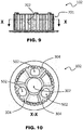
- Figure 9 shows a side view of the movable hub, in which the external drawing surface 702 of the drawing element 701 is visible.
- Figure 10 shows a bottom view of the movable hub 102 according to section X-X of Figure 9 .
- the movable hub 102 comprises a plurality of housing sockets 502 that are configured for housing the respective closing springs 104, outside which the columnar fixing elements 501 already described are insertable.
- the housing sockets 502 have at least one section having an elongated shape along a direction that is tangential to the movable hub 102.
- Figure 11 shows a cross-sectional perspective view of the fixed hub 101 and of the movable hub 102.
- the hubs are just partially disassembled with each other (in an exemplified and not operating configuration), so that it is easier to observe the interaction between the first sliding elements 303 and the second sliding elements 304.
- the first sliding surfaces of the first sliding elements 303 and the second sliding surfaces of the second sliding elements 304 are configured for interacting with each other, since they are in contact in the operating position: in particular, said sliding surfaces, resting one upon the other, mutually slide along a helix trajectory according to which they are sloped, under the respective conditions in which they are subjected to a driving torque or to a motoring torque, according to what has already been described.
- the interaction of the first sliding surfaces with the second sliding surfaces involves a partial rotation and especially a variation of the relative distance between the movable hub 102 and the fixed hub 101.
- the housing sockets 502 comprise respective holed end abutment surfaces 503, through which the columnar fixing elements 501 are inserted, along with the respective closing springs 104.
- the annular retaining element 105 (not visible in Figure 11 ) is preferably constrained to the columnar fixing elements 501 by means of suitable screws 504, so as to retain the closing springs 104 (not visible in Figure 11 ) in the respective housing sockets 502.
- the closing springs 104 could be replaced by springs of the "belleville” or “cup” type, by suitably sizing the sliding elements and the respective surfaces, thus making the housing sockets or the fixing columnar elements superfluous in some possible embodiments.
- Figure 12 exemplifies the method for mounting the clutch 100.
- a movable hub 102 comprising a central access hole 302 is provided.
- a fixed hub 101 comprising a central coupling hole 301 for a rotating shaft of the vehicle is also provided.
- a plurality of discs 103 mounted on the movable hub 102 is provided.
- the fixed hub 101 and the movable hub 102 are shaped so as to rotate jointly with each other.
- the fixed hub 101 and the movable hub 102 are also shaped so as to slide axially with each other, getting farther or closer with each other during the joined rotation, so that the fixed hub 102 and the movable hub 102, preferably through respective flanges, exert a variable axial load onto the plurality of discs 103.
- the embodiment of the clutch unit represented in sub- figure 12(c) thus essentially represents a clutch according to the present invention when it is provided pre-assembled.
- At least the fixed hub 101, the movable hub 102 and the plurality of discs 103 are preferably provided in a pre-assembled clutch unit, whose mounting occurs directly on the rotating shaft of the concerned vehicle.
- a plurality of closing springs 104 are provided in respective housing sockets, along with an annular retaining element 105 that retains them.
- the annular retaining element 105 is retained by suitable screws 504 constrained to columnar fixing elements.
- the central access hole 302 makes the central coupling hole 301 clearly accessible, as it is also visible in the figure, passing internally through the plurality of discs interposed 103, in order to operate locking means with a rotating shaft, as it will be further described.
- the annular retaining element 105 results proximal to the free face of the flange of the movable hub 102 and comprises a central shaping that is sized so as not to impede access to the central access hole 301 of the fixed hub 101, for installing the pre-assembled clutch unit.
- the clutch unit thus pre-assembled is configured for being inserted into a clutch housing (not shown), in particular coupling thereto the driving discs between the discs 103, in order to proceed with the mounting, as it will be successively described.
- the central coupling hole 301 is coupled with a rotating shaft 1200 of the vehicle, preferably a primary gear shaft.
- Suitable locking means 1201 are also prepared, preferably comprising a locking nut and a relative washer.
- the central coupling hole 301 is coupled with the rotating shaft 1200, in particular at a threaded end thereof.
- the central access hole 302 it is easy to access the area of the central coupling hole 301, internally through the plurality of discs 103 interposed. In this way, it is possible to operate the locking means 1201, for instance by tightening the nut, in order to integrally constrain the central coupling hole with the rotating shaft 1200.
- a pusher 106 is inserted into the central access hole 302 of the movable hub 102.
- the pusher 106 has a diameter such as to be inserted into the central access hole and therein to be coupled with the movable hub 102 being retained by retaining means 1202 such as a Seeger ring.
- the pusher 106 is configured for commanding the disengagement of the clutch, according to what has already been described.
- the clutch according to the present invention does not require a dedicated "push-plate” element, but it actually allows saving a component compared to a "three-piece” clutch, providing the appropriate functionality through the features of the components described herein.
- Figure 13 shows a cross-sectional side view of the clutch 100, in which it is possible to notice the internal components already described.
- the clutch according to the present invention can advantageously be provided pre-assembled, with a pack of discs 103 already closed, thus simplifying its installation and mounting on the vehicle. Moreover, the tightening of the locking means (such as the nut) on the rotating shaft is simplified, to the advantage of a better ease of installation and servicing.
- the structure of the clutch according to the present invention by providing an external drawing surface 702 of the movable hub 102 that couples with all of the driven discs 202, allows a better modulation of the clutch.
- a clutch according to the present invention is less affected by wear effects, since it can use discs with an optimal resistant section.
- the structure of the clutch according to the present invention it becomes possible to choose the helix pitch of the sliding surfaces with greater freedom of design.
- the axial assembly of the fixed hub 101 on the movable hub 102 it is not necessary to identify a unique initial position, but it is possible to merge the hubs together in any radial position in which the coupling elements are configured for engaging, for instance 120° according to the preferred embodiments.
- Figure 14 shows an alternative embodiment of a fixed hub 1101 of a clutch according to the present invention.
- the fixed hub 1101 comprises first sliding elements 1303 supported by radial ribs.
- the first sliding elements 1303 respectively comprise first sliding surfaces 1403, 1403b, 1403c sloped according to a helix.
- each sliding element 1303 comprises a respective plurality of sliding surfaces 1403, 1403b, 1403c sloped according to a helix.
- sliding surfaces 1403, 1403b, 1403c individually have surfaces smaller than the sliding surfaces 403 already described, but they overall identify an equivalent sliding surface.
- the sliding element 1303 provides a plurality of sliding surfaces that are functionally equivalent to the embodiment of the already described sliding element 303.
- Figure 15 shows an alternative embodiment of a movable hub 1102 of a clutch according to the present invention.
- the movable hub 1102 is configured for being mounted along an axial direction on the fixed hub 1101, already described.
- the movable hub 1102 comprises a plurality of second sliding elements 1304, 1304b, 1304c.
- the second sliding elements 1304, 1304b, 1304c are adjacent to the internal surface of the drawing element 701.
- the plurality of second sliding elements 1304, 1304b, 1304c respectively comprise a plurality of second sliding surfaces 1404, 1404b, 1404c sloped according to a helix.
- sliding surfaces 1403, 1403b and 1403c of the first sliding elements 1303 of the fixed hub 1101 are configured for sliding on the respective sliding surfaces 1404, 1404b, 1404c of the second sliding elements 1304, 1304b, 1304c.
- the sliding surfaces 1404, 1404b, 1404c individually have surfaces smaller than the sliding surfaces 404 already described, but they overall identify an equivalent sliding surface.
- the sliding elements 1304, 1304b, 1304c provide a plurality of sliding surfaces that are functionally equivalent to the embodiment of the sliding element 304 already described. In this way, though ensuring an unaltered operation of the clutch having optimal modulation, there is a reduction in the overall dimensions in the radial direction.
- the fixed hub 1101 and the movable hub 1102 are configured for having sliding surfaces 1304, 1304b, 1304c and respectively 1403, 1403b and 1403c, which can mate with each other and which are adapted to slide under the action of a driving torque acting onto the clutch, according to what has already been described.
- sliding element 1303 and the second sliding elements 1304, 1304b, 1304c comprise further sliding surfaces (not denoted by reference numbers, for clarity in the figures) that are opposite the ones considered and that can mate with each other and are adapted to slide under the action of a motoring torque acting onto the clutch, according to what has already been described.
- a fixed hub and/or a movable hub of the clutch according to the present invention can advantageously be structured so as to be obtained from a die-casting single piece, thus avoiding undercuts problems; this precaution improves the industrialization of the product.
- the sliding elements of opposed sliding surfaces could be provided, which have helix angles different from each other, in order to confer a different operation of the clutch when the fixed and movable hubs get closer or farther with each other, since they correspond to the contact of some sliding surfaces or to the contact of the opposite sliding surfaces. In this way, it becomes possible to confer a different modulation and response of the clutch that is optimized for the features of the vehicle.
- sliding surfaces for operation under "wide open throttle” conditions with a certain helix pitch, for example of 1200 mm
- opposite sliding surfaces could be provided for "motoring" operation with a helix pitch smaller than the aforesaid, for instance of 900 mm.
Landscapes
- Engineering & Computer Science (AREA)
- General Engineering & Computer Science (AREA)
- Mechanical Engineering (AREA)
- Mechanical Operated Clutches (AREA)
Description
- The present invention relates to a clutch, in particular a pre-assembled clutch, and to a method for mounting a clutch.
- In particular, the invention relates to a clutch comprising a fixed hub and a moveable hub, between which a plurality of clutch discs is interposed, which allow transmitting a torque when they are axially pushed towards each other.
- In general, the invention relates to clutches for commanding the engagement of a rotary movement between rotating shafts, in particular in land vehicles and more particularly in motorcycles.
- The use of a mechanical element called "clutch" for connecting two shafts with each other in rotary motion in a controlled manner is known.
- Known clutches use a plurality of circular-crown plates or discs called "driving" or "driven" discs according to their function. The driving discs are constrained to a shaft connected to an engine, whereas the driven discs are constrained to a driven shaft of a user transmission.
- Document
EP2827016 (A1 ) relates to a power transmitting apparatus which can transmit a torque necessary for performing the pushing start of engine. - Document
EP2778457 (A1 ) relates to a power transmitting apparatus comprising a clutch housing rotatable together with an input member connected to an engine and mounted thereon a plurality of driving-side clutch discs; a clutch member connected to an output member; a plurality of driven-side clutch discs arranged between the driving-side clutch discs alternately therewith; a pressure member for forcing the driving-side clutch discs and the driven-side cutch discs to be press-contacted each other and to release the press-contacting force acting on them in accordance with approach or separation of the pressure member relative to the clutch member; and a kick-starter means. - Document
JPS60184719 (A - Document
JPS50119837 (U - Document
EP2921735 (A1 ) relates to a multi-plate friction clutch including a clutch outer, a clutch centre, clutch plates, and a pressure plate. - Document
US2009071792 (A1 ) relates to a clutch housing rotatable together with an input member and supporting a plurality of driving clutch plates; a pressure member can be mounted on the clutch member so as to be axially movable therealong so as to accommodate pressure-contact and release of the driving clutch plates and the driven clutch plates; back-torque limiting cams can be configured to release the connection between the driving clutch plates and the driven clutch plates. - Document
EP2930387 (A1 ) relates to a clutch apparatus in which an opening is provided on a fixed cam member fixed to an output power shaft so as to form a cam mechanism together with a movable cam member. - Document
JPH08145074 (A - Document
EP1058018 (A2 ) to Adler S.p.A. relates to a clutch comprising a fixed hub, a movable hub, a plurality of discs and a pressure plate that, moving in an axial direction, allows engagement and disengagement of the clutch. - Known clutches adopt complex configurations that involve the presence of numerous, differently shaped elements to be assembled with each other.
- Furthermore, in general, known clutches adopt mounting solutions that make their installation on the vehicle complex and laborious, since typically each of the discs must be installed singularly.
- An object of the present invention is to solve some prior art problems.
- A particular object of the present invention is to provide a clutch whose components have an optimized operation, so as to reduce the number and complexity thereof.
- A further particular object of the present invention is to provide a clutch whose components are rationally assemblable with each other, thus simplifying the installation thereof.
- Further general objects of the present invention contemplate providing the clutch with proper modulation and command smoothness, meanwhile effectively transferring the driving torque and moreover providing the clutch with proper reliability and resistance during use.
- These and other objects are achieved by a clutch according to
claim 1 and by a method for mounting a clutch according to claim 12. - A solution idea underlying the present invention is to provide a clutch comprising: a fixed hub with a central coupling hole configured for coupling with a rotating shaft; a moveable hub configured for being mounted along an axial direction onto the fixed hub; a plurality of discs configured for being interposed between the fixed hub and the moveable hub. The fixed hub and the moveable hub are shaped so as to rotate jointly with each other and so as to axially slide with each other, getting farther or closer such that the fixed hub and the moveable hub exert a variable axial load onto the plurality of discs, thereby transmitting a torque.
- According to the present invention, the moveable hub of the clutch comprises a central access hole configured for allowing access to the central coupling hole of the fixed hub, passing internally through the plurality of discs interposed, so as to operate locking means and to provide coupling of the clutch with the rotating shaft.
- In particular, the clutch structure comprising a fixed hub and a moveable hub thus configured is advantageous in terms of assembly, since it has a more rational structure that does not need a pressure plate separated from the moveable hub.
- By using a fixed hub and a moveable hub thus configured, it is possible to provide a clutch having a structure essentially consisting of the two hubs, thereby preserving all of the functionality features and reducing the complexity of the assembly.
- Furthermore, advantageously, the central access hole simplifies the installation and mounting of the clutch, thus allowing locking means, such as a nut, to reach and lock the central coupling hole of the fixed hub on the rotating shaft.
- In general, advantageously, the clutch according to the present invention can be pre-assembled and moreover allows reducing the number and complexity of the constitutive elements, to the advantage of an optimal operation and a more simplified maintenance for the vehicle on which the clutch is installed.
- Preferably, by providing a plurality of discs mounted on the moveable hub, it is possible to provide a clutch having better modulation and command smoothness, transferring the driving torque on all of the driven discs even during the engagement, to the advantage of a better modulation.
- According to a further aspect of the present invention, a method for mounting a clutch is provided, which comprises: providing a fixed hub comprising a central coupling hole; providing a moveable hub comprising a central access hole; providing a plurality of discs, in particular mounted on the moveable hub; providing the moveable hub mounted along an axial direction on the fixed hub, wherein the discs result interposed between the fixed hub and the moveable hub, and wherein the fixed hub and the moveable hub are shaped so as to rotate jointly with each other and so as to axially slide with each other, getting farther or closer so that the fixed hub and the moveable hub exert a variable axial load onto the plurality of discs, thereby transmitting a torque; coupling the central coupling hole with a rotating shaft; access the central coupling hole, through the central access hole and internally through the plurality of interposed discs; operating locking means so as to constrain the central coupling hole onto the rotating shaft.
- In general, the method for mounting a clutch provides performing the mounting according to the aspects and details of the clutch according to the present invention.
- Further features and advantages will become apparent from the following detailed description of a non-limiting preferred embodiment of the present invention and from the dependent claims, which outline preferred and particularly advantageous embodiments of the invention.
- The invention is disclosed with reference to the following figures, given by non-limiting example, wherein:
-
Figure 1 shows a preferred embodiment of a clutch according to the present invention. -
Figure 2 shows an exploded view of the clutch ofFigure 1 . -
Figure 3 shows an exploded view of the fixed hub, of the moveable hub and of the pusher of the clutch ofFigure 1 . -
Figure 4 shows a top view of the fixed hub ofFigure 3 . -
Figure 5 shows a side view of the fixed hub ofFigure 3 . -
Figure 6 shows a cross-sectional top view of the fixed hub ofFigure 3 . -
Figure 7 shows a perspective bottom view of the moveable hub ofFigure 3 . -
Figure 8 shows a further view of the moveable hub ofFigure 7 . -
Figure 9 shows a side view of the moveable hub ofFigure 7 . -
Figure 10 shows a cross-sectional view of the moveable hub ofFigure 7 . -
Figure 11 shows a cross-sectional perspective view of the fixed hub and of the moveable hub of the clutch ofFigure 1 . -
Figure 12 in sub-figures (a) to (h) exemplifies the method for mounting the clutch ofFigure 1 . -
Figure 13 shows a cross-sectional side view of the clutch ofFigure 1 , once it has been assembled. -
Figure 14 shows an alternative embodiment of a fixed hub of a clutch according to the present invention. -
Figure 15 shows an alternative embodiment of a moveable hub of a clutch according to the present invention. - In different figures, analogous elements will be indicated by analogous reference numbers.
- With reference to the example of
Figure 1 , a preferred embodiment of aclutch 100 according to the present invention is shown. - The
clutch 100 is of the two-piece type, comprising a fixed hub and a moveable hub, without a separated pressure plate acting onto the moveable hub. - In this embodiment, the
clutch 100 is used to command the engagement of a rotary movement between an engine shaft and a primary gear fitted on a clutch housing in a vehicle, in particular in a motorcycle. -
Figure 2 shows an exploded view of theclutch 100, wherein the components are individually identifiable. - The
clutch 100 comprises afixed hub 101, in particular configured for being coupled with a rotating shaft of the vehicle on which the clutch is installed. - The
clutch 100 then comprises amoveable hub 102, configured for being axially mounted on thefixed hub 101. - The
clutch 100 comprises a plurality ofdiscs 103, which are interposed between thefixed hub 101 and themoveable hub 102. - In particular, the
discs 103 comprise a plurality ofclutch discs 201 or driving discs, in particular coated discs, which comprise protruding elements configured for coupling with a clutch housing (not shown), which is in turn preferably connected to a driving shaft of the vehicle. - The
discs 103 then comprise a plurality of drivendiscs 202, which comprise an internal toothing that is configured for coupling with themoveable hub 102, and which are arranged alternatively with respect to theclutch discs 201. Moreover, preferably, thediscs 103 comprise a turned driving disc, a cup spring and a spacer ring positioned proximally to the flange of themovable hub 102. - The
fixed hub 101 and themoveable hub 102 are shaped so as to rotate jointly with each other when they are axially mounted; in this way, thefixed hub 101 and themoveable hub 102 are adapted to receive a torque. - Moreover, the
fixed hub 101 and themoveable hub 102 are shaped so as to axially slide with each other, getting farther or closer such as to reduce or increase the axial force intensity on thediscs 103. In this way, thefixed hub 101 and themoveable hub 102 exert a variable axial load on thediscs 103, so that when thediscs 103 are compressed with each other by the axial load, the clutch 100 allows transmitting a torque between the housing and the rotating shaft of the engine; on the other side, when the axial load decreases and thediscs 103 are free to slide with each other, since thefixed hub 101 and themoveable hub 102 are sufficiently distanced, the clutch results disengaged, substantially without any transmitted torque. - By suitable sliding elements that will be described more in detail, the
fixed hub 101 and themoveable hub 102 are configured for getting closer to each other when they are subjected to a driving torque, namely a torque provided by the engine of the vehicle, and are also configured for being distanced from each other when they are subjected to a motoring torque, i.e. a torque contrary to the driving torque provided by the engine of the vehicle. - Preferably, the clutch 100 further comprises a plurality of closing springs 104, preferably with respective spring spacers. Said closing springs 104 are configured for applying a closing axial load acting between the
movable hub 102 and thefixed hub 101, so as to transmit the torque through the clutch discs. The sliding elements are configured for facilitating said closure, by getting the movable hub close to the fixed hub, so as to allow the use of less stiff springs for transmitting a same torque value, to the advantage of a greater ease of clutch command. - Preferably, the clutch 100 further comprises an
annular retaining element 105 for thesprings 104, which is retained by suitable fixing means such as screws, preferably fixed to thefixed hub 101 as it will be further described. In a variant, not shown, the retainingelement 105 could be semi-annular or of other suitable shapes. - Moreover, preferably, the clutch 100 comprises a
pusher 106 that is configured for commanding disengagement of the clutch 100 by getting themovable hub 102 farther from the fixedhub 101. Preferably, thepusher 106 is retained in a suitable seat provided on themoveable hub 102 by suitable retaining means, such as a Seeger ring. Preferably, thepusher 106 comprises a rolling element, such as a roller bearing. - The clutch 100 is a multi-plate one, wherein the
movable hub 102 comprises a flange having a free external face, namely not internally engaged in the coupling with thefixed hub 101. The flange of themovable hub 102 performs the pressure plate function. Themovable hub 102 further comprises a drawing element provided with grooves, in which the teeth of the driven discs engage, as it will be further described. - The
fixed hub 101 of the clutch 100 is instead constrained to a rotating shaft, preferably to the primary shaft of the gearbox. - The closing springs 104 provide a force that gets the
fixed hub 101 and themoveable hub 102 axially closer to each other, thus closing thediscs 103. - Preferably, the closing springs 104 have a suitable spring constant that can confer a lever command that is light and smooth.
- Advantageously, there is a further force that gets the
fixed hub 101 and themovable hub 102 axially closer to each other, thus closing thediscs 103; said force is provided by the sliding elements that are on the respectivemovable hub 102 and fixedhub 101, which slide with respect to each other constrained in mutual rotation by a grooved coupling having a helical path. - The direction of the helix of the sliding elements is such that, by accelerating, the
movable hub 102 and thefixed hub 101 tend to "close" with respect to each other, thus increasing the axial load acting onto the pack of thediscs 103, which is added to the force of thesprings 104. - On the contrary, when the motoring torque is sufficiently greater than the driving torque (typically during the throttle release phase or in the braking phase on a motorcycle), the direction of the helix of the sliding elements is such that the
movable hub 101 and thefixed hub 102 tend to "open" with respect to each other, counteracting the force of thesprings 104 and obtaining the effect of reducing the axial load acting onto the discs, in a completely automatic way and with no need of "user operation". - In the clutch 100, the slope of the sliding elements, like the
springs 104, is thus a calibration element for the system: the more inclined the grooves, the greater the influence of the torque on the load applied onto thediscs 103. - Therefore, the clutch 100 provides a torque enthralling effect, in addition to a slipper clutch function with back-torque limiter.
- The torque enthralling effect allows reducing (in general more than halve) the axial load that the
springs 104 must provide, drastically reducing the effort required at the lever to command the clutch, thus making the driving/ riding more comfortable. -
Figure 3 shows an exploded view of thefixed hub 101, of themovable hub 102 and of thepusher 106. - In this view it is possible to notice that the
fixed hub 101 comprises acentral coupling hole 301 that is shaped so as to provide a coupling with a rotating shaft of the vehicle. - In this view it is further possible to notice that the
movable hub 102 comprises acentral access hole 302, in particular made on the flange of themovable hub 102. - Said
central access hole 302 allows access to thecentral coupling hole 301 once the clutch has been assembled. In particular, thecentral access hole 302 allows accessing thecentral coupling hole 301 by passing internally through thediscs 103 interposed (not visible inFigure 3 ) and unimpeded by the further elements of thefixed hub 101 or of themovable hub 102. - In this way, through the
central access hole 302, it is possible to introduce and operate locking means, such as for instance a nut, for stably coupling thefixed hub 101 with the respective rotating shaft, on which thecentral coupling hole 301 is mounted. - In this way, it is possible to provide a
pre-assembled clutch 100, as it will be further described. - Preferably the locking means comprise a nut, introduced during mounting by passing through the
central access hole 302. Preferably, the nut is configured for fixing thecentral coupling hole 301 by threading directly on a threaded end of a rotating shaft, of the engine of the concerned vehicle. - According to a possible variant of the locking means (not shown), a clip or elastic-ring locking system could be provided, which could be already arranged inside the pre-assembled clutch and simply be operated for locking, through the access provided by the
central access hole 302. This variant would be suitable for low loads, where no stresses occur, which may compromise the coupling on the rotating shaft. - The
fixed hub 101 preferably comprises first slidingelements 303, configured for interacting with respective second sliding elements (not visible) inside themovable hub 102, to define sliding surfaces according to a helix that imposes a spacing movement according to a predetermined law between themovable hub 102 and thefixed hub 101, according to what has already been described. - In general, the particular structure of the
fixed hub 101 comprising the first slidingelements 303 separated from each other allows a better lubricant flow directly on the drawing zone engaged by theclutch discs 103. -
Figure 4 shows a top view of thefixed hub 101, in which the first slidingelements 303 are better visible. - The first sliding
elements 303 comprise respective first slidingsurfaces surfaces - In particular, the sliding
surfaces fixed hub 101 and lie on planes that are sloped by a helix angle with respect to the axis of thefixed hub 101. - Preferably, the
fixed hub 101 comprises two or more first sliding elements that are arranged radially along a perimeter of thefixed hub 101. Two sliding elements would in fact be enough to ensure the operation of the clutch; a greater number of sliding elements can allow a better operation for the clutch, thus there are three sliding elements in the preferred example considered herein. - In the preferred embodiment of
Figure 3 , each of the three slidingelements 303 comprises at least one respective slidingsurface -
Figure 5 shows a side view of thefixed hub 101, in which thecolumnar fixing elements 501, which are configured for passing through the closing springs 104, are visible. -
Figure 6 shows a top view of thefixed hub 101 according to section VI-VI ofFigure 5 . - In this sectional view it is possible to notice that the sliding
elements 303 are internally hollow, in order to reduce the weight of thefixed hub 101. -
Figure 7 shows a perspective bottom view of themovable hub 102. - The
movable hub 102 preferably comprises second slidingelements 304, configured for interacting with the first slidingelements 303 of thefixed hub 101, already described. - The second sliding
elements 304 comprise respective second slidingsurfaces surfaces - In other words, the second sliding
surfaces movable hub 102 and lie on planes that are sloped by a same helix angle, compared with the helix angle of the first slidingsurfaces fixed hub 101. - In other words, the first sliding
surfaces surfaces - Preferably, the helix according to which the sliding surfaces are arranged has a predetermined pitch, with values preferably comprised between 250 mm and 3000 mm, in particular for clutches in oil bath. The value of the helix pitch is determinable based on the operation characteristics desired for the clutch and based on the type and specificity of the vehicle on which it is installed.
- In general, it has been established that preferred values of the helix angle, considered the angle of the sliding surface with respect to an axial vertical of the movable hub and of the fixed hub, are such to be: comprised between 1° and 30°, preferably comprised between 3° and 6° for dry clutches and preferably comprised between 10° and 20° for clutches in oil bath (of the "wet" type). Such values are illustrative but not limiting of the adoptable helix angles.
- Once the
movable hub 102 has been axially mounted on thefixed hub 101, the second slidingsurfaces surfaces 304 or 304b. In this way, the second slidingsurfaces surfaces 304 or 304b, are adapted to get themovable hub 102 closer or farther with respect to thefixed hub 101, when they are subjected to a torque, thus varying the axial load that compresses thediscs 103, according to what has already been described. - Preferably, the
movable hub 102 respectively comprises three or more second slidingelements 304, congruently with thefixed hub 101 with which it couples. The slidingelements 304 are also radially arranged along a perimeter of themovable hub 102. As said, two or more second sliding elements, congruently with thefixed hub 101, would be appropriate. - Moreover, the
movable hub 102 preferably comprises acylindrical drawing element 701, which comprises anexternal drawing surface 702. Said drawingelement 701 preferably has a "shell" structure, i.e. internally hollow. - The
drawing element 701 is configured for housing the plurality ofdiscs 103, which are assembled thereon. - The
external drawing surface 702 of thedrawing element 701 is shaped so as to couple with the toothing of the drivendiscs 202, in particular comprising a plurality of grooves parallel to each other. - In the preferred embodiment, all of the driven discs are coupled with the
external drawing surface 702 of themovable hub 102; this allows operating with sliding surfaces having higher helix pitches, to the advantage of a better modulation of the clutch during the engagement. - Preferably, the
external drawing surface 702 comprises a plurality of through-holes for lubricant fluid, not visible in the figure. -
Figure 8 shows a bottom view of themovable hub 102. - In the preferred embodiment of
Figure 8 , each of the slidingelements 304 comprises a respective slidingsurface 404 that occupies a whole lateral face, so as to maximize the available sliding surface and to improve the operation and modulation of the clutch. - Preferably, also the
surface 404b opposite the slidingsurface 404 constitutes a sliding surface of the slidingelement 304, which is engaged when the clutch is subjected to a motoring torque, instead of a driving torque. - The second sliding
elements 304 of themovable hub 102 are adjacent to aninternal surface 801 of thedrawing element 701. More preferably, the second slidingsurface 404 of themovable hub 102 is contiguous to theinternal surface 801 of thedrawing element 701. - In general, the second sliding
elements 304 of themovable hub 102 could be proximal, namely could have a distance from theinternal surface 801 of thedrawing element 701 that is less than the magnitude of a preponderant dimension of the second sliding elements themselves. - With the second sliding
elements 304 proximal, preferably adjacent, to thedrawing element 701, it is possible to free space in the central area of themovable hub 102. As a consequence, advantageously, the dimension of thecentral access hole 302 can be greater, and, inside the clutch, access to thecentral coupling hole 301 of thefixed hub 101 is improved with a consequent improvement of the pre-assembled clutch installation. -
Figure 9 shows a side view of the movable hub, in which theexternal drawing surface 702 of thedrawing element 701 is visible. -
Figure 10 shows a bottom view of themovable hub 102 according to section X-X ofFigure 9 . - The
movable hub 102 comprises a plurality ofhousing sockets 502 that are configured for housing the respective closing springs 104, outside which thecolumnar fixing elements 501 already described are insertable. - In order to facilitate the passage of the
columnar fixing elements 501 during the mounting of thefixed hub 101 and of themovable hub 102, and to allow the operation of the clutch when themovable hub 102 gets closer or farther with respect to thefixed hub 101, thehousing sockets 502 have at least one section having an elongated shape along a direction that is tangential to themovable hub 102. - In this way, by respecting the constraint imposed by the respective sliding surfaces, it is possible to couple the
movable hub 102 and thefixed hub 101 axially with each other, with a slight rotation for the assembly, as it will be further described. -
Figure 11 shows a cross-sectional perspective view of thefixed hub 101 and of themovable hub 102. - In this view, the hubs are just partially disassembled with each other (in an exemplified and not operating configuration), so that it is easier to observe the interaction between the first sliding
elements 303 and the second slidingelements 304. In fact, the first sliding surfaces of the first slidingelements 303 and the second sliding surfaces of the second slidingelements 304 are configured for interacting with each other, since they are in contact in the operating position: in particular, said sliding surfaces, resting one upon the other, mutually slide along a helix trajectory according to which they are sloped, under the respective conditions in which they are subjected to a driving torque or to a motoring torque, according to what has already been described. - In this way, the interaction of the first sliding surfaces with the second sliding surfaces involves a partial rotation and especially a variation of the relative distance between the
movable hub 102 and thefixed hub 101. - Preferably, the
housing sockets 502 comprise respective holed end abutment surfaces 503, through which thecolumnar fixing elements 501 are inserted, along with the respective closing springs 104. - The annular retaining element 105 (not visible in
Figure 11 ) is preferably constrained to thecolumnar fixing elements 501 by means ofsuitable screws 504, so as to retain the closing springs 104 (not visible inFigure 11 ) in therespective housing sockets 502. - In a variant of the clutch (not represented), the closing springs 104 could be replaced by springs of the "belleville" or "cup" type, by suitably sizing the sliding elements and the respective surfaces, thus making the housing sockets or the fixing columnar elements superfluous in some possible embodiments.
-
Figure 12 exemplifies the method for mounting the clutch 100. - In sub-
figure 12(a) , amovable hub 102 comprising acentral access hole 302 is provided. Separately, afixed hub 101 comprising acentral coupling hole 301 for a rotating shaft of the vehicle is also provided. - In sub-
figure 12(b) , a plurality ofdiscs 103 mounted on themovable hub 102 is provided. - In sub-
figure 12(c) , themovable hub 102 mounted in the axial direction on thefixed hub 101 is provided. In this configuration, thediscs 103 result interposed between thefixed hub 101 and themovable hub 102. - The
fixed hub 101 and themovable hub 102 are shaped so as to rotate jointly with each other. Thefixed hub 101 and themovable hub 102 are also shaped so as to slide axially with each other, getting farther or closer with each other during the joined rotation, so that thefixed hub 102 and themovable hub 102, preferably through respective flanges, exert a variable axial load onto the plurality ofdiscs 103. - The embodiment of the clutch unit represented in sub-
figure 12(c) thus essentially represents a clutch according to the present invention when it is provided pre-assembled. - Indeed, at least the
fixed hub 101, themovable hub 102 and the plurality ofdiscs 103 are preferably provided in a pre-assembled clutch unit, whose mounting occurs directly on the rotating shaft of the concerned vehicle. - In sub-
figure 12(d) , a plurality of closing springs 104 are provided in respective housing sockets, along with anannular retaining element 105 that retains them. Theannular retaining element 105 is retained bysuitable screws 504 constrained to columnar fixing elements. - In sub-
figure 12(e) , the preferred embodiment of the pre-assembled clutch unit is shown. Since said clutch unit has pre-assembled closing springs and annular retaining element, it allows easy access, internally through the plurality ofdiscs 103, to thecentral coupling hole 301, so as to allow the mounting thereof directly on the rotating shaft of the concerned vehicle. - In fact, the
central access hole 302 makes thecentral coupling hole 301 clearly accessible, as it is also visible in the figure, passing internally through the plurality of discs interposed 103, in order to operate locking means with a rotating shaft, as it will be further described. - In particular, the
annular retaining element 105 results proximal to the free face of the flange of themovable hub 102 and comprises a central shaping that is sized so as not to impede access to thecentral access hole 301 of thefixed hub 101, for installing the pre-assembled clutch unit. - The clutch unit thus pre-assembled is configured for being inserted into a clutch housing (not shown), in particular coupling thereto the driving discs between the
discs 103, in order to proceed with the mounting, as it will be successively described. - In sub-
figure 12(f) , thecentral coupling hole 301 is coupled with arotating shaft 1200 of the vehicle, preferably a primary gear shaft. Suitable locking means 1201 are also prepared, preferably comprising a locking nut and a relative washer. - In sub-
figure 12(g) , thecentral coupling hole 301 is coupled with therotating shaft 1200, in particular at a threaded end thereof. Through thecentral access hole 302 it is easy to access the area of thecentral coupling hole 301, internally through the plurality ofdiscs 103 interposed. In this way, it is possible to operate the locking means 1201, for instance by tightening the nut, in order to integrally constrain the central coupling hole with therotating shaft 1200. - It is clear that the mounting operation of the clutch according to the present invention is practical and convenient.
- In sub-
figure 12(h) , apusher 106 is inserted into thecentral access hole 302 of themovable hub 102. Thepusher 106 has a diameter such as to be inserted into the central access hole and therein to be coupled with themovable hub 102 being retained by retainingmeans 1202 such as a Seeger ring. Thepusher 106 is configured for commanding the disengagement of the clutch, according to what has already been described. - It should be thus noticed that the clutch according to the present invention does not require a dedicated "push-plate" element, but it actually allows saving a component compared to a "three-piece" clutch, providing the appropriate functionality through the features of the components described herein.
-
Figure 13 shows a cross-sectional side view of the clutch 100, in which it is possible to notice the internal components already described. - It is clear that in the clutch 100, by simply removing the retaining
element 1202 and thepusher 106, it is possible to access thecentral coupling hole 301 by internally passing through the plurality ofdiscs 103 interposed between thefixed hub 101 and themovable hub 102. - The clutch according to the present invention can advantageously be provided pre-assembled, with a pack of
discs 103 already closed, thus simplifying its installation and mounting on the vehicle. Moreover, the tightening of the locking means (such as the nut) on the rotating shaft is simplified, to the advantage of a better ease of installation and servicing. - The structure of the clutch according to the present invention, by providing an
external drawing surface 702 of themovable hub 102 that couples with all of the drivendiscs 202, allows a better modulation of the clutch. - Moreover, thanks to the better transfer of the torque on the discs, a clutch according to the present invention is less affected by wear effects, since it can use discs with an optimal resistant section.
- Then, thanks to the structure of the clutch according to the present invention it becomes possible to choose the helix pitch of the sliding surfaces with greater freedom of design. In particular, it is possible to select higher values for the helix pitch of the sliding surfaces, to the advantage of a lesser wear and a more modulable response of the clutch command.
- Advantageously, for the axial assembly of the
fixed hub 101 on themovable hub 102, it is not necessary to identify a unique initial position, but it is possible to merge the hubs together in any radial position in which the coupling elements are configured for engaging, for instance 120° according to the preferred embodiments. -
Figure 14 shows an alternative embodiment of afixed hub 1101 of a clutch according to the present invention. - The
fixed hub 1101 comprises first slidingelements 1303 supported by radial ribs. The first slidingelements 1303 respectively comprise first slidingsurfaces element 1303 comprises a respective plurality of slidingsurfaces - It is noticed that the sliding
surfaces surfaces 403 already described, but they overall identify an equivalent sliding surface. - In other words, the sliding
element 1303 provides a plurality of sliding surfaces that are functionally equivalent to the embodiment of the already described slidingelement 303. - In this way, though ensuring an unaltered operation of the clutch having optimal modulation, there is a reduction in dimensions in the radial direction.
-
Figure 15 shows an alternative embodiment of amovable hub 1102 of a clutch according to the present invention. - The
movable hub 1102 is configured for being mounted along an axial direction on thefixed hub 1101, already described. - The
movable hub 1102 comprises a plurality of second slidingelements elements drawing element 701. - The plurality of second sliding
elements surfaces - It is clear that the sliding
surfaces elements 1303 of the fixedhub 1101 are configured for sliding on the respective slidingsurfaces elements - It is furthermore noticed that the sliding
surfaces surfaces 404 already described, but they overall identify an equivalent sliding surface. In other words, the slidingelements element 304 already described. In this way, though ensuring an unaltered operation of the clutch having optimal modulation, there is a reduction in the overall dimensions in the radial direction. - The specific numbering of the elements used in
Figures 14 and 15 is to be considered illustrative and not limiting, meaning that i) not all sliding elements and sliding surfaces have been denoted, in order not to diminish the clarity of the figure; ii) not necessarily is there a unique correspondence between first and second sliding surfaces as denoted, but the skilled person understands that said surfaces are configured for being arranged side by side to each other and for sliding with each other. - It is clear that the
fixed hub 1101 and themovable hub 1102 are configured for having slidingsurfaces - Likewise, the sliding
element 1303 and the second slidingelements - In general, a fixed hub and/or a movable hub of the clutch according to the present invention can advantageously be structured so as to be obtained from a die-casting single piece, thus avoiding undercuts problems; this precaution improves the industrialization of the product.
- Moreover, in an alternative embodiment (not shown), the sliding elements of opposed sliding surfaces could be provided, which have helix angles different from each other, in order to confer a different operation of the clutch when the fixed and movable hubs get closer or farther with each other, since they correspond to the contact of some sliding surfaces or to the contact of the opposite sliding surfaces. In this way, it becomes possible to confer a different modulation and response of the clutch that is optimized for the features of the vehicle.
- For instance, it could be possible to provide sliding surfaces for operation under "wide open throttle" conditions with a certain helix pitch, for example of 1200 mm, whereas opposite sliding surfaces could be provided for "motoring" operation with a helix pitch smaller than the aforesaid, for instance of 900 mm.
- Considering the above reported disclosure, the skilled person will be able to conceive further changes and variants, in order to meet contingent and specific needs. Therefore, the embodiments herein described are provided by way of non-limiting examples of the invention.
Claims (13)
- Clutch (100) comprising:a fixed hub (101, 1101) comprising a central coupling hole (301), said central coupling hole (301) being configured for coupling with a rotating shaft (1200);a movable hub (102, 1102) configured for being mounted along an axial direction onto said fixed hub (101, 1101);a plurality of discs (103) configured for being interposed between said fixed hub (101, 1101) and said movable hub (102, 1102);wherein said fixed hub (101, 1101) and said movable hub (102, 1102) are shaped so as to rotate jointly with each other and so as to slide axially with each other, getting farther or closer such that said fixed hub (101, 1101) and said movable hub (102, 1102) exert a variable axial load onto said plurality of discs (103) thereby transmitting a torque,the clutch (100) being characterised in that,said movable hub (102, 1102) comprises a central access hole (302), said central access hole (302) being configured for allowing access to said central coupling hole (301) passing internally through said plurality of discs (103) interposed, so as to operate locking means (1201) for said coupling with said rotating shaft (1200),wherein said fixed hub (101, 1101) comprises first sliding elements (303, 1303), respectively comprising first sliding surfaces (403, 403b; 1403, 1403b, 1403c) sloped according to a helix,and wherein said movable hub (102, 1202) comprises second sliding elements (304; 1304, 1304b, 1034c), respectively comprising second sliding surfaces (404, 404b; 1404, 1404b, 1404c) sloped according to said helix and configured for mating with said first sliding surfaces (403, 403b; 1403, 1403b, 1403c),said first sliding surfaces (403, 403b; 1403, 1403b, 1403c) and said second sliding surfaces (404, 404b; 1404, 1404b, 1404c) being adapted to move said movable hub (102, 1102) farther or closer with respect to said fixed hub (101, 1101) when subjected to a torque, so as to vary said axial load onto said plurality of discs (103),wherein said movable hub (102, 1102) further comprises a cylindrical drawing element (701) comprising an external drawing surface (702),said plurality of discs (103) being assembled onto said drawing element (701) of said movable hub (102, 1102),said drawing surface (702) being shaped so as to couple with an internal toothing of driven discs (202),and wherein said second sliding elements (304; 1304, 1304b, 1034c) of said movable hub (102, 1102) are adjacent to an internal surface (801) of said drawing element (701).
- Clutch according to claim 1,
wherein said drawing surface (702) is configured to couple with an internal toothing of all of the driven discs (202) among said plurality of discs (103). - Clutch according to claim 1 or 2,
wherein said second sliding surfaces (404, 404b; 1404, 1404b, 1404c) are contiguous with said internal surface (801) of said drawing element (701). - Clutch according to any one of claims 1 to 3,
comprising at least two said first sliding elements (303, 1303) and respective at least two (304, 1304) said second sliding elements, radially arranged along respective perimeters of said fixed hub (101, 1101) and said movable hub (102, 1102). - Clutch according to any one of claims 1 to 4,
wherein each of said first sliding elements (303) comprises at least one first sliding surface (403, 403b) occupying a whole lateral face of said each of said first sliding elements (303),
and wherein each of said second sliding elements (304) comprises at least one second sliding surface (404, 404b) occupying a whole lateral face of said each of said second sliding elements (304). - Clutch according to any one of claims 1 to 5,
wherein each of said first sliding elements (1303) comprises a respective plurality of said first sliding surfaces (1403, 1403b, 1403c),
and wherein each of said second sliding elements (1304, 1304b, 1034c) comprises a respective plurality of said second sliding surfaces (1404, 1404b, 1404c). - Clutch according to any one of claims 1 to 6,
further comprising a plurality of closing springs (104) configured for applying an axial closing load between said fixed hub (101, 1101) and said movable hub (102, 1102),
wherein said movable hub (102, 1102) further comprises a respective plurality of housing sockets (502) for said closing springs (104), said housing sockets (502) comprising respective abutment holed end surfaces (503),
and wherein said fixed hub (101, 1101) further comprises a respective plurality of columnar fixing elements (501) configured for being inserted in said housing sockets (502) through said abutment holed end surfaces (503) so as to internally pass through said closing springs (104),
said clutch (100) further comprising an annular retaining element (105) configured for being constrained to said columnar fixing elements (501) for retaining said closing springs (104) within said housing sockets (502). - Clutch according to claim 7,
wherein said annular retaining element (105) is proximal to a free face of a flange of said movable hub (102, 1102) and comprises a central shaping being sized so as not to impede access to said central access hole (302) of said movable hub (102, 1102). - Clutch according to claim 7 or 8,
wherein said second sliding elements (304) of said movable hub (102) respectively comprise said housing sockets (502) for said closing springs (104), said housing sockets (502) preferably comprising at least one section having elongated shape along a direction tangential to said movable hub (102), so as to allow passage of said columnar fixing elements (501) during mounting and/or operating of said movable hub (102) onto said fixed hub (101). - Clutch according to any one of claims 1 to 9,
further comprising a pusher (106) having a diameter such as to be inserted in said central access hole (302) of said movable hub (102) and therein retained by retaining means (1202),
said pusher (106) being configured for commanding disengagement of said clutch (100) by distancing said movable hub (102, 1102) with respect to said fixed hub (101, 1101). - Clutch according to any one of claims 1 to 10, wherein at least said fixed hub (101, 1101), at least said movable hub (102, 1102) and at least said plurality of discs (103) are provided as a pre-assembled clutch unit.
- Method for mounting a clutch (100) according to any one of claims 1 to 11, comprising:providing a fixed hub (101, 1101) comprising a central coupling hole (301);providing a movable hub (102, 1102) comprising a central access hole (302);providing a plurality of discs (103), preferably mounted onto said movable hub (102, 1102);providing said movable hub (102, 1102) mounted along an axial direction onto said fixed hub (101, 1101), said discs (103) resulting interposed between said fixed hub (101, 1101) and said movable hub (102, 1102), said fixed hub (101, 1101) and said movable hub (102, 1102) being shaped so as to rotate jointly with each other and to slide axially with each other, getting farther or closer such that said fixed hub (101, 1101) and said movable hub (102, 1102) exert a variable axial load onto said plurality of discs (103) thereby transmitting a torque;coupling said central coupling hole (301) with a rotating shaft (1200);accessing said central coupling hole (301), passing through said central access hole (302) and internally through said plurality of discs (103) interposed;operating locking means (1201) so as to constrain said central coupling hole (301) onto said rotating shaft (1200).
- Method for mounting according to claim 12, wherein at least said movable hub (102, 1202), at least said plurality of discs (103) and at least said fixed hub (101, 1101) are provided pre-assembled with each other.
Applications Claiming Priority (2)
| Application Number | Priority Date | Filing Date | Title |
|---|---|---|---|
| IT102017000031815A IT201700031815A1 (en) | 2017-03-22 | 2017-03-22 | Clutch, in particular clutch for motorcycles, and relative mounting method |
| PCT/EP2018/056508 WO2018172176A1 (en) | 2017-03-22 | 2018-03-15 | Clutch, in particular clutch for motorcycles, and related mounting method |
Publications (2)
| Publication Number | Publication Date |
|---|---|
| EP3601829A1 EP3601829A1 (en) | 2020-02-05 |
| EP3601829B1 true EP3601829B1 (en) | 2020-12-09 |
Family
ID=59700000
Family Applications (1)
| Application Number | Title | Priority Date | Filing Date |
|---|---|---|---|
| EP18713157.8A Active EP3601829B1 (en) | 2017-03-22 | 2018-03-15 | Clutch, in particular clutch for motorcycles, and related mounting method |
Country Status (6)
| Country | Link |
|---|---|
| US (1) | US11156254B2 (en) |
| EP (1) | EP3601829B1 (en) |
| CN (1) | CN110709616B (en) |
| IT (1) | IT201700031815A1 (en) |
| TW (1) | TWI803483B (en) |
| WO (1) | WO2018172176A1 (en) |
Families Citing this family (14)
| Publication number | Priority date | Publication date | Assignee | Title |
|---|---|---|---|---|
| JP6553696B2 (en) * | 2017-10-26 | 2019-07-31 | 株式会社エフ・シー・シー | Clutch device |
| IT201800009859A1 (en) * | 2018-10-29 | 2020-04-29 | Adler Spa | Clutch and related transmission system for a vehicle, in particular for a motorcycle |
| WO2020255101A1 (en) * | 2019-06-21 | 2020-12-24 | Stm Italy S.R.L. | Driven disk clutch sub-unit for a motorcycle or other handlebar vehicle |
| IT201900020414A1 (en) * | 2019-11-05 | 2021-05-05 | Stm Italy Srl | SUB-ASSEMBLY OF DRIVEN DISC CLUTCH FOR A MOTORCYCLE OR OTHER VEHICLE WITH HANDLEBARS |
| CN111255815A (en) * | 2020-01-17 | 2020-06-09 | 重庆隆鑫机车有限公司 | Reinforced clutch and engine |
| CN111255816A (en) * | 2020-01-17 | 2020-06-09 | 重庆隆鑫机车有限公司 | Slip clutch and engine |
| JP7225461B1 (en) * | 2022-06-30 | 2023-02-20 | 株式会社エフ・シー・シー | Clutch device and motorcycle |
| JP7403702B1 (en) | 2022-07-05 | 2023-12-22 | 株式会社エフ・シー・シー | clutch device |
| WO2024009771A1 (en) | 2022-07-05 | 2024-01-11 | 株式会社エフ・シー・シー | Clutch device |
| JP7291309B1 (en) | 2022-07-15 | 2023-06-14 | 株式会社エフ・シー・シー | Clutch device and motorcycle |
| JP7581288B2 (en) | 2022-07-21 | 2024-11-12 | 株式会社エフ・シー・シー | Clutch device |
| CN117703950B (en) | 2022-09-13 | 2024-12-20 | 株式会社F.C.C. | Clutch device and motorcycle |
| JP7434641B1 (en) | 2022-09-28 | 2024-02-20 | 株式会社エフ・シー・シー | Clutch devices and motorcycles |
| JP7853526B1 (en) | 2024-12-27 | 2026-04-28 | 株式会社エフ・シー・シー | Clutch device |
Family Cites Families (22)
| Publication number | Priority date | Publication date | Assignee | Title |
|---|---|---|---|---|
| JPS5322678Y2 (en) * | 1974-03-15 | 1978-06-13 | ||
| JPS60184719A (en) * | 1984-02-29 | 1985-09-20 | Yamaha Motor Co Ltd | Clutch |
| JP2896322B2 (en) * | 1994-11-25 | 1999-05-31 | 川崎重工業株式会社 | Clutch device |
| CN2359519Y (en) * | 1998-12-24 | 2000-01-19 | 徐国权 | Clutch of motorcycle |
| IT1312454B1 (en) | 1999-05-18 | 2002-04-17 | Adler Spa | DISC CLUTCH EQUIPPED WITH HELICAL VEHICLES FOR THE DYNAMIC ADJUSTMENT OF THE AXIAL COMPRESSION OF THE DISCS |
| CN2490362Y (en) * | 2001-08-27 | 2002-05-08 | 周凤民 | Safety energy saver for engine of motorcycle |
| JP2005325993A (en) * | 2004-01-14 | 2005-11-24 | F C C:Kk | Power transmission device |
| JP4527055B2 (en) * | 2005-12-28 | 2010-08-18 | 株式会社エフ・シー・シー | Power transmission device |
| JP4452301B2 (en) * | 2007-09-12 | 2010-04-21 | 株式会社エフ・シー・シー | Power transmission device |
| CN201507574U (en) * | 2009-09-29 | 2010-06-16 | 林长森 | Motorcycle clutch pressure plate |
| JP5879094B2 (en) * | 2011-10-27 | 2016-03-08 | 株式会社エフ・シー・シー | Power transmission device |
| JP5847551B2 (en) * | 2011-11-17 | 2016-01-27 | 株式会社エフ・シー・シー | Clutch device |
| JP5854900B2 (en) * | 2012-03-16 | 2016-02-09 | 株式会社エフ・シー・シー | Power transmission device |
| CN105229326B (en) * | 2013-03-15 | 2017-12-26 | 舍弗勒技术股份两合公司 | Clutch device |
| JP6113681B2 (en) * | 2014-03-17 | 2017-04-12 | 本田技研工業株式会社 | Multi-plate friction clutch |
| JP6215749B2 (en) * | 2014-03-31 | 2017-10-18 | 本田技研工業株式会社 | Clutch device |
| JP6384123B2 (en) * | 2014-05-27 | 2018-09-05 | 株式会社ジェイテクト | Driving force transmission device |
| DE102014219967A1 (en) * | 2014-10-01 | 2016-04-07 | Schaeffler Technologies AG & Co. KG | Clutch device for a motorcycle and torque transmission device or clutch |
| JP6376662B2 (en) * | 2015-05-12 | 2018-08-22 | 株式会社エフ・シー・シー | Power transmission system for vehicles |
| JP6649067B2 (en) * | 2015-12-04 | 2020-02-19 | 株式会社エクセディ | Motorcycle clutch device |
| JP6894792B2 (en) * | 2017-07-27 | 2021-06-30 | 株式会社エフ・シー・シー | Power transmission device |
| JP6553696B2 (en) * | 2017-10-26 | 2019-07-31 | 株式会社エフ・シー・シー | Clutch device |
-
2017
- 2017-03-22 IT IT102017000031815A patent/IT201700031815A1/en unknown
-
2018
- 2018-03-15 CN CN201880020152.4A patent/CN110709616B/en active Active
- 2018-03-15 EP EP18713157.8A patent/EP3601829B1/en active Active
- 2018-03-15 US US16/496,833 patent/US11156254B2/en active Active
- 2018-03-15 WO PCT/EP2018/056508 patent/WO2018172176A1/en not_active Ceased
- 2018-03-21 TW TW107109668A patent/TWI803483B/en active
Non-Patent Citations (1)
| Title |
|---|
| None * |
Also Published As
| Publication number | Publication date |
|---|---|
| CN110709616B (en) | 2021-08-13 |
| US20200318694A1 (en) | 2020-10-08 |
| TWI803483B (en) | 2023-06-01 |
| CN110709616A (en) | 2020-01-17 |
| EP3601829A1 (en) | 2020-02-05 |
| TW201839284A (en) | 2018-11-01 |
| US11156254B2 (en) | 2021-10-26 |
| IT201700031815A1 (en) | 2018-09-22 |
| WO2018172176A1 (en) | 2018-09-27 |
Similar Documents
| Publication | Publication Date | Title |
|---|---|---|
| EP3601829B1 (en) | Clutch, in particular clutch for motorcycles, and related mounting method | |
| EP3717790B1 (en) | Clutch, in particular for a motorcycle, with pressure plate and centrifugal assembly | |
| US4228883A (en) | Automatic wear adjuster for Belleville spring clutches | |
| GB2369416A (en) | Clutch assembly | |
| US7810624B1 (en) | Centrifugal clutch with expansion ring assembly | |
| GB2338036A (en) | Wrap-spring clutch for vehicle driveline | |
| KR20150096418A (en) | Clutch with slack adjuster, in particular for a motor vehicle | |
| US3779353A (en) | Friction clutch, especially for motor vehicles | |
| WO2018194078A1 (en) | Friction clutch | |
| GB2224808A (en) | Phase change mechanism | |
| KR102639407B1 (en) | Torque transmission unit and drive train | |
| US6053296A (en) | Friction clutch with wear take-up device, especially for motor vehicles | |
| US6755294B2 (en) | Pressure plate assembly for a friction clutch | |
| US5927454A (en) | Input shaft sleeve for a clutch release assembly | |
| KR102548139B1 (en) | friction clutch device | |
| JP4975847B2 (en) | Clutch device | |
| JP4072741B2 (en) | Synchronizer | |
| US7147093B2 (en) | Centrifugal clutch | |
| US7823713B1 (en) | Hydraulic clutch with expansion ring assembly | |
| GB2338997A (en) | Friction clutch | |
| EP0879371A1 (en) | A power transmitting arrangement | |
| US7063199B2 (en) | Centrifugal clutch | |
| US20040112702A1 (en) | Transmission torque-transmitting mechanism having a ball ramp electric motor apply mechanism | |
| EP4008923B1 (en) | Clutch with centrifugal assembly, especially for a motorcycle | |
| GB2169989A (en) | Torsional vibration damper with rotation-rate-dependent friction device |
Legal Events
| Date | Code | Title | Description |
|---|---|---|---|
| STAA | Information on the status of an ep patent application or granted ep patent |
Free format text: STATUS: UNKNOWN |
|
| STAA | Information on the status of an ep patent application or granted ep patent |
Free format text: STATUS: THE INTERNATIONAL PUBLICATION HAS BEEN MADE |
|
| PUAI | Public reference made under article 153(3) epc to a published international application that has entered the european phase |
Free format text: ORIGINAL CODE: 0009012 |
|
| STAA | Information on the status of an ep patent application or granted ep patent |
Free format text: STATUS: REQUEST FOR EXAMINATION WAS MADE |
|
| 17P | Request for examination filed |
Effective date: 20191021 |
|
| AK | Designated contracting states |
Kind code of ref document: A1 Designated state(s): AL AT BE BG CH CY CZ DE DK EE ES FI FR GB GR HR HU IE IS IT LI LT LU LV MC MK MT NL NO PL PT RO RS SE SI SK SM TR |
|
| AX | Request for extension of the european patent |
Extension state: BA ME |
|
| GRAP | Despatch of communication of intention to grant a patent |
Free format text: ORIGINAL CODE: EPIDOSNIGR1 |
|
| RAP1 | Party data changed (applicant data changed or rights of an application transferred) |
Owner name: ENDURANCE ADLER S.P.A. |
|
| STAA | Information on the status of an ep patent application or granted ep patent |
Free format text: STATUS: GRANT OF PATENT IS INTENDED |
|
| DAV | Request for validation of the european patent (deleted) | ||
| DAX | Request for extension of the european patent (deleted) | ||
| INTG | Intention to grant announced |
Effective date: 20200625 |
|
| GRAS | Grant fee paid |
Free format text: ORIGINAL CODE: EPIDOSNIGR3 |
|
| GRAA | (expected) grant |
Free format text: ORIGINAL CODE: 0009210 |
|
| STAA | Information on the status of an ep patent application or granted ep patent |
Free format text: STATUS: THE PATENT HAS BEEN GRANTED |
|
| AK | Designated contracting states |
Kind code of ref document: B1 Designated state(s): AL AT BE BG CH CY CZ DE DK EE ES FI FR GB GR HR HU IE IS IT LI LT LU LV MC MK MT NL NO PL PT RO RS SE SI SK SM TR |
|
| REG | Reference to a national code |
Ref country code: GB Ref legal event code: FG4D |
|
| REG | Reference to a national code |
Ref country code: AT Ref legal event code: REF Ref document number: 1343760 Country of ref document: AT Kind code of ref document: T Effective date: 20201215 Ref country code: CH Ref legal event code: EP |
|
| REG | Reference to a national code |
Ref country code: DE Ref legal event code: R096 Ref document number: 602018010670 Country of ref document: DE |
|
| REG | Reference to a national code |
Ref country code: IE Ref legal event code: FG4D |
|
| PG25 | Lapsed in a contracting state [announced via postgrant information from national office to epo] |
Ref country code: FI Free format text: LAPSE BECAUSE OF FAILURE TO SUBMIT A TRANSLATION OF THE DESCRIPTION OR TO PAY THE FEE WITHIN THE PRESCRIBED TIME-LIMIT Effective date: 20201209 Ref country code: RS Free format text: LAPSE BECAUSE OF FAILURE TO SUBMIT A TRANSLATION OF THE DESCRIPTION OR TO PAY THE FEE WITHIN THE PRESCRIBED TIME-LIMIT Effective date: 20201209 Ref country code: NO Free format text: LAPSE BECAUSE OF FAILURE TO SUBMIT A TRANSLATION OF THE DESCRIPTION OR TO PAY THE FEE WITHIN THE PRESCRIBED TIME-LIMIT Effective date: 20210309 Ref country code: GR Free format text: LAPSE BECAUSE OF FAILURE TO SUBMIT A TRANSLATION OF THE DESCRIPTION OR TO PAY THE FEE WITHIN THE PRESCRIBED TIME-LIMIT Effective date: 20210310 |
|
| REG | Reference to a national code |
Ref country code: AT Ref legal event code: MK05 Ref document number: 1343760 Country of ref document: AT Kind code of ref document: T Effective date: 20201209 |
|
| PG25 | Lapsed in a contracting state [announced via postgrant information from national office to epo] |
Ref country code: BG Free format text: LAPSE BECAUSE OF FAILURE TO SUBMIT A TRANSLATION OF THE DESCRIPTION OR TO PAY THE FEE WITHIN THE PRESCRIBED TIME-LIMIT Effective date: 20210309 Ref country code: LV Free format text: LAPSE BECAUSE OF FAILURE TO SUBMIT A TRANSLATION OF THE DESCRIPTION OR TO PAY THE FEE WITHIN THE PRESCRIBED TIME-LIMIT Effective date: 20201209 Ref country code: SE Free format text: LAPSE BECAUSE OF FAILURE TO SUBMIT A TRANSLATION OF THE DESCRIPTION OR TO PAY THE FEE WITHIN THE PRESCRIBED TIME-LIMIT Effective date: 20201209 |
|
| REG | Reference to a national code |
Ref country code: NL Ref legal event code: MP Effective date: 20201209 |
|
| PG25 | Lapsed in a contracting state [announced via postgrant information from national office to epo] |
Ref country code: NL Free format text: LAPSE BECAUSE OF FAILURE TO SUBMIT A TRANSLATION OF THE DESCRIPTION OR TO PAY THE FEE WITHIN THE PRESCRIBED TIME-LIMIT Effective date: 20201209 Ref country code: HR Free format text: LAPSE BECAUSE OF FAILURE TO SUBMIT A TRANSLATION OF THE DESCRIPTION OR TO PAY THE FEE WITHIN THE PRESCRIBED TIME-LIMIT Effective date: 20201209 |
|
| REG | Reference to a national code |
Ref country code: LT Ref legal event code: MG9D |
|
| PG25 | Lapsed in a contracting state [announced via postgrant information from national office to epo] |
Ref country code: PT Free format text: LAPSE BECAUSE OF FAILURE TO SUBMIT A TRANSLATION OF THE DESCRIPTION OR TO PAY THE FEE WITHIN THE PRESCRIBED TIME-LIMIT Effective date: 20210409 Ref country code: RO Free format text: LAPSE BECAUSE OF FAILURE TO SUBMIT A TRANSLATION OF THE DESCRIPTION OR TO PAY THE FEE WITHIN THE PRESCRIBED TIME-LIMIT Effective date: 20201209 Ref country code: LT Free format text: LAPSE BECAUSE OF FAILURE TO SUBMIT A TRANSLATION OF THE DESCRIPTION OR TO PAY THE FEE WITHIN THE PRESCRIBED TIME-LIMIT Effective date: 20201209 Ref country code: SM Free format text: LAPSE BECAUSE OF FAILURE TO SUBMIT A TRANSLATION OF THE DESCRIPTION OR TO PAY THE FEE WITHIN THE PRESCRIBED TIME-LIMIT Effective date: 20201209 Ref country code: SK Free format text: LAPSE BECAUSE OF FAILURE TO SUBMIT A TRANSLATION OF THE DESCRIPTION OR TO PAY THE FEE WITHIN THE PRESCRIBED TIME-LIMIT Effective date: 20201209 Ref country code: EE Free format text: LAPSE BECAUSE OF FAILURE TO SUBMIT A TRANSLATION OF THE DESCRIPTION OR TO PAY THE FEE WITHIN THE PRESCRIBED TIME-LIMIT Effective date: 20201209 Ref country code: CZ Free format text: LAPSE BECAUSE OF FAILURE TO SUBMIT A TRANSLATION OF THE DESCRIPTION OR TO PAY THE FEE WITHIN THE PRESCRIBED TIME-LIMIT Effective date: 20201209 |
|
| PG25 | Lapsed in a contracting state [announced via postgrant information from national office to epo] |
Ref country code: AT Free format text: LAPSE BECAUSE OF FAILURE TO SUBMIT A TRANSLATION OF THE DESCRIPTION OR TO PAY THE FEE WITHIN THE PRESCRIBED TIME-LIMIT Effective date: 20201209 Ref country code: PL Free format text: LAPSE BECAUSE OF FAILURE TO SUBMIT A TRANSLATION OF THE DESCRIPTION OR TO PAY THE FEE WITHIN THE PRESCRIBED TIME-LIMIT Effective date: 20201209 |
|
| REG | Reference to a national code |
Ref country code: DE Ref legal event code: R097 Ref document number: 602018010670 Country of ref document: DE |
|
| PG25 | Lapsed in a contracting state [announced via postgrant information from national office to epo] |
Ref country code: IS Free format text: LAPSE BECAUSE OF FAILURE TO SUBMIT A TRANSLATION OF THE DESCRIPTION OR TO PAY THE FEE WITHIN THE PRESCRIBED TIME-LIMIT Effective date: 20210409 |
|
| PLBE | No opposition filed within time limit |
Free format text: ORIGINAL CODE: 0009261 |
|
| STAA | Information on the status of an ep patent application or granted ep patent |
Free format text: STATUS: NO OPPOSITION FILED WITHIN TIME LIMIT |
|
| PG25 | Lapsed in a contracting state [announced via postgrant information from national office to epo] |
Ref country code: AL Free format text: LAPSE BECAUSE OF FAILURE TO SUBMIT A TRANSLATION OF THE DESCRIPTION OR TO PAY THE FEE WITHIN THE PRESCRIBED TIME-LIMIT Effective date: 20201209 Ref country code: MC Free format text: LAPSE BECAUSE OF FAILURE TO SUBMIT A TRANSLATION OF THE DESCRIPTION OR TO PAY THE FEE WITHIN THE PRESCRIBED TIME-LIMIT Effective date: 20201209 |
|
| REG | Reference to a national code |
Ref country code: CH Ref legal event code: PL |
|
| 26N | No opposition filed |
Effective date: 20210910 |
|
| PG25 | Lapsed in a contracting state [announced via postgrant information from national office to epo] |
Ref country code: DK Free format text: LAPSE BECAUSE OF FAILURE TO SUBMIT A TRANSLATION OF THE DESCRIPTION OR TO PAY THE FEE WITHIN THE PRESCRIBED TIME-LIMIT Effective date: 20201209 Ref country code: SI Free format text: LAPSE BECAUSE OF FAILURE TO SUBMIT A TRANSLATION OF THE DESCRIPTION OR TO PAY THE FEE WITHIN THE PRESCRIBED TIME-LIMIT Effective date: 20201209 |
|
| REG | Reference to a national code |
Ref country code: BE Ref legal event code: MM Effective date: 20210331 |
|
| PG25 | Lapsed in a contracting state [announced via postgrant information from national office to epo] |
Ref country code: ES Free format text: LAPSE BECAUSE OF FAILURE TO SUBMIT A TRANSLATION OF THE DESCRIPTION OR TO PAY THE FEE WITHIN THE PRESCRIBED TIME-LIMIT Effective date: 20201209 Ref country code: CH Free format text: LAPSE BECAUSE OF NON-PAYMENT OF DUE FEES Effective date: 20210331 Ref country code: IE Free format text: LAPSE BECAUSE OF NON-PAYMENT OF DUE FEES Effective date: 20210315 Ref country code: LU Free format text: LAPSE BECAUSE OF NON-PAYMENT OF DUE FEES Effective date: 20210315 Ref country code: LI Free format text: LAPSE BECAUSE OF NON-PAYMENT OF DUE FEES Effective date: 20210331 |
|
| PG25 | Lapsed in a contracting state [announced via postgrant information from national office to epo] |
Ref country code: IS Free format text: LAPSE BECAUSE OF FAILURE TO SUBMIT A TRANSLATION OF THE DESCRIPTION OR TO PAY THE FEE WITHIN THE PRESCRIBED TIME-LIMIT Effective date: 20210409 |
|
| PG25 | Lapsed in a contracting state [announced via postgrant information from national office to epo] |
Ref country code: BE Free format text: LAPSE BECAUSE OF NON-PAYMENT OF DUE FEES Effective date: 20210331 |
|
| P01 | Opt-out of the competence of the unified patent court (upc) registered |
Effective date: 20230509 |
|
| PG25 | Lapsed in a contracting state [announced via postgrant information from national office to epo] |
Ref country code: CY Free format text: LAPSE BECAUSE OF FAILURE TO SUBMIT A TRANSLATION OF THE DESCRIPTION OR TO PAY THE FEE WITHIN THE PRESCRIBED TIME-LIMIT Effective date: 20201209 |
|
| PG25 | Lapsed in a contracting state [announced via postgrant information from national office to epo] |
Ref country code: HU Free format text: LAPSE BECAUSE OF FAILURE TO SUBMIT A TRANSLATION OF THE DESCRIPTION OR TO PAY THE FEE WITHIN THE PRESCRIBED TIME-LIMIT; INVALID AB INITIO Effective date: 20180315 |
|
| PG25 | Lapsed in a contracting state [announced via postgrant information from national office to epo] |
Ref country code: MK Free format text: LAPSE BECAUSE OF FAILURE TO SUBMIT A TRANSLATION OF THE DESCRIPTION OR TO PAY THE FEE WITHIN THE PRESCRIBED TIME-LIMIT Effective date: 20201209 |
|
| PG25 | Lapsed in a contracting state [announced via postgrant information from national office to epo] |
Ref country code: TR Free format text: LAPSE BECAUSE OF FAILURE TO SUBMIT A TRANSLATION OF THE DESCRIPTION OR TO PAY THE FEE WITHIN THE PRESCRIBED TIME-LIMIT Effective date: 20201209 |
|
| PG25 | Lapsed in a contracting state [announced via postgrant information from national office to epo] |
Ref country code: MT Free format text: LAPSE BECAUSE OF FAILURE TO SUBMIT A TRANSLATION OF THE DESCRIPTION OR TO PAY THE FEE WITHIN THE PRESCRIBED TIME-LIMIT Effective date: 20201209 |
|
| PGFP | Annual fee paid to national office [announced via postgrant information from national office to epo] |
Ref country code: IT Payment date: 20250326 Year of fee payment: 8 |
|
| PGFP | Annual fee paid to national office [announced via postgrant information from national office to epo] |
Ref country code: GB Payment date: 20260220 Year of fee payment: 9 |
|
| PGFP | Annual fee paid to national office [announced via postgrant information from national office to epo] |
Ref country code: DE Payment date: 20260219 Year of fee payment: 9 |
|
| PGFP | Annual fee paid to national office [announced via postgrant information from national office to epo] |
Ref country code: FR Payment date: 20260219 Year of fee payment: 9 |