EP2921735A1 - Multi-plate friction clutch - Google Patents
Multi-plate friction clutch Download PDFInfo
- Publication number
- EP2921735A1 EP2921735A1 EP15158764.9A EP15158764A EP2921735A1 EP 2921735 A1 EP2921735 A1 EP 2921735A1 EP 15158764 A EP15158764 A EP 15158764A EP 2921735 A1 EP2921735 A1 EP 2921735A1
- Authority
- EP
- European Patent Office
- Prior art keywords
- centre
- clutch
- bottom wall
- wall part
- ring
- Prior art date
- Legal status (The legal status is an assumption and is not a legal conclusion. Google has not performed a legal analysis and makes no representation as to the accuracy of the status listed.)
- Granted
Links
- 238000005461 lubrication Methods 0.000 abstract description 10
- 230000002093 peripheral effect Effects 0.000 description 9
- 238000002485 combustion reaction Methods 0.000 description 8
- 230000005540 biological transmission Effects 0.000 description 6
- 238000005452 bending Methods 0.000 description 1
- 239000002184 metal Substances 0.000 description 1
- 238000005192 partition Methods 0.000 description 1
- 230000002000 scavenging effect Effects 0.000 description 1
- 239000007858 starting material Substances 0.000 description 1
Images




Classifications
-
- F—MECHANICAL ENGINEERING; LIGHTING; HEATING; WEAPONS; BLASTING
- F16—ENGINEERING ELEMENTS AND UNITS; GENERAL MEASURES FOR PRODUCING AND MAINTAINING EFFECTIVE FUNCTIONING OF MACHINES OR INSTALLATIONS; THERMAL INSULATION IN GENERAL
- F16D—COUPLINGS FOR TRANSMITTING ROTATION; CLUTCHES; BRAKES
- F16D13/00—Friction clutches
- F16D13/22—Friction clutches with axially-movable clutching members
- F16D13/38—Friction clutches with axially-movable clutching members with flat clutching surfaces, e.g. discs
- F16D13/52—Clutches with multiple lamellae ; Clutches in which three or more axially moveable members are fixed alternately to the shafts to be coupled and are pressed from one side towards an axially-located member
- F16D13/54—Clutches with multiple lamellae ; Clutches in which three or more axially moveable members are fixed alternately to the shafts to be coupled and are pressed from one side towards an axially-located member with means for increasing the effective force between the actuating sleeve or equivalent member and the pressure member
- F16D13/56—Clutches with multiple lamellae ; Clutches in which three or more axially moveable members are fixed alternately to the shafts to be coupled and are pressed from one side towards an axially-located member with means for increasing the effective force between the actuating sleeve or equivalent member and the pressure member in which the clutching pressure is produced by springs only
-
- F—MECHANICAL ENGINEERING; LIGHTING; HEATING; WEAPONS; BLASTING
- F16—ENGINEERING ELEMENTS AND UNITS; GENERAL MEASURES FOR PRODUCING AND MAINTAINING EFFECTIVE FUNCTIONING OF MACHINES OR INSTALLATIONS; THERMAL INSULATION IN GENERAL
- F16D—COUPLINGS FOR TRANSMITTING ROTATION; CLUTCHES; BRAKES
- F16D13/00—Friction clutches
- F16D13/58—Details
- F16D13/72—Features relating to cooling
-
- F—MECHANICAL ENGINEERING; LIGHTING; HEATING; WEAPONS; BLASTING
- F16—ENGINEERING ELEMENTS AND UNITS; GENERAL MEASURES FOR PRODUCING AND MAINTAINING EFFECTIVE FUNCTIONING OF MACHINES OR INSTALLATIONS; THERMAL INSULATION IN GENERAL
- F16D—COUPLINGS FOR TRANSMITTING ROTATION; CLUTCHES; BRAKES
- F16D2300/00—Special features for couplings or clutches
- F16D2300/24—Concentric actuation rods, e.g. actuation rods extending concentrically through a shaft
Definitions
- the present invention relates to a multi-plate friction clutch.
- a wet multi-plate friction clutch in which plural clutch plates and plural friction plates, alternately disposed in an overlapping manner in a ring-shaped space between an outer cylindrical part of a clutch outer and a centre cylindrical part of a clutch centre, are set between a centre bottom wall part of the clutch centre and a pressure plate.
- the oil guided from an oil passage formed in the rotation shaft to the bearing leaks from the bearing and flows out to the space between the outer bottom wall part and the centre bottom wall part. Then, part of the oil that has flowed out flows in the centrifugal direction along the outer surface of the centre bottom wall part, and furthermore, part of this oil passes through the oil conduction hole to enter the inner surface side of the centre bottom wall part.
- the oil that has passed through the oil conduction hole is guided to the inner circumferential surface of the centre cylindrical part on the inner surface side of the centre bottom wall part, and leaves from plural small holes formed in the centre cylindrical part to the outer circumferential side of the centre cylindrical part to be supplied to the alternating clutch plates and friction plates.
- part of the oil that has leaked from the bearing and has flowed out to the space between the outer bottom wall part and the centre bottom wall part passes through the oil conduction hole and enters the inner surface side of the centre bottom wall part to lubricate lubrication sites of the multi-plate friction clutch. Therefore, lubrication with a sufficient amount of oil is difficult.
- the present invention is made in view of this point and it is an object of at least the preferred embodiments to provide a multi-plate friction clutch in which lubrication sites of the clutch can be efficiently supplied with oil and be sufficiently lubricated.
- a multi-plate friction clutch comprising: a clutch outer which has a bottomed cylindrical shape and in which an outer cylindrical part extends along an axial direction from an outer circumferential edge of an outer bottom wall part whose centre is journaled by a rotation shaft with intermediary of a bearing; a clutch centre in which a centre cylindrical part is formed inside the outer cylindrical part and extends from a centre bottom wall part whose centre is journaled by the rotation shaft with restriction of relative rotation, the centre cylindrical part extending away from the outer bottom wall part, and the centre bottom wall part facing an inner surface of the outer bottom wall part and having a plurality of communication holes formed at an equal distance from an axial centre; a plurality of friction plates engaging with the outer cylindrical part and a plurality of clutch plates engaging with the centre cylindrical part which are arranged alternately in the axial direction overlapping with each other in a ring-shaped space between the outer cylindrical part and the centre cylindrical part; and a pressure plate that sandwiches the friction plates and the clutch plates
- the centre ring protrusion protruding into a cylindrical shape from the outer surface of the centre bottom wall part is formed at substantially the same radial position as the plural communication holes. Furthermore, the ring recess opened toward the axial centre is formed in the inner circumferential surface of the centre ring protrusion and the communication holes are so opened as to face the ring recess. Therefore, oil that has leaked from the bearing and has flowed out to a space between the outer bottom wall part and the centre bottom wall part is discharged in the centrifugal direction due to rotation.
- the ring recess opened toward the axial centre in the centre ring protrusion protruding on the outer surface of the centre bottom wall part can efficiently receive and accumulate most of this oil discharged in the centrifugal direction.
- the oil accumulated in the ring recess can be made to pass through the communication holes and be efficiently supplied to lubrication sites such as the friction plates and the clutch plates on the inner surface side of the centre bottom wall part.
- the lubrication sites in the multi-plate friction clutch can be sufficiently lubricated, and connection and disconnection of the clutch can be made smooth.
- an inner circumferential surface of the centre cylindrical part is formed radially outside relative to the communication holes, and a plurality of small holes that allow an inner circumferential surface side and an outer circumferential surface side of the centre cylindrical part to communicate with each other are formed in the centre cylindrical part.
- oil guided to the inner surface side of the centre bottom wall part via the communication holes can pass through the small holes from the inner circumferential surface side of the centre cylindrical part and is smoothly supplied to the friction plates and the clutch plates on the outer circumferential surface side.
- an outer ring protrusion projecting in a cylindrical shape from the inner surface of the outer bottom wall part, is formed radially inside relative to the centre ring protrusion, and the outer ring protrusion protrudes to an axial position of the ring recess.
- an oil thrower groove is formed in a ring shape in an outer circumferential surface of the outer ring protrusion.
- the lubrication sites in the multi-plate friction clutch can be sufficiently lubricated through the communication holes.
- an axial position of the outer ring protrusion overlaps with an axial position of an opening end part of a gap in which the bearing to journal the outer bottom wall part is interposed.
- the oil leaked from the opening end part of the gap in which the bearing is interposed can be efficiently received by the inner circumferential surface of the outer ring protrusion, and can be guided to the protrusion end.
- FIGS. 1 to 8 A currently preferred embodiment of the present invention will be described below based on FIGS. 1 to 8 .
- FIG. 1 is a right side view of an internal combustion engine E from which a case cover has been removed.
- FIG. 2 is a cross-sectional development view of the internal combustion engine taken along line II-II in FIG. 1 .
- the internal combustion engine E is a water-cooled, single-cylinder, four-stroke internal combustion engine, which may be mounted in a motorcycle.
- a transmission chamber 11 m that is partitioned by a partition wall and houses a transmission M is formed on the rear side of the crank chamber 11 c.
- the single-cylinder, four-stroke internal combustion engine E has, over the crank chamber 11c of the crankcase 11, an engine main body composed of a cylinder block 12 having one cylinder 12a, a cylinder head 13 joined to the upper part of the cylinder block 12 by stud bolts with the intermediary of a gasket, and a cylinder head cover 14 joined to the upper part of the cylinder head 13.
- the cylinder block 12, the cylinder head 13, and the cylinder head cover 14 stacked over the crankcase 11 project upward with a posture such that they are tilted slightly forward from the crankcase 11.
- a main shaft 21 and a countershaft 22 of the transmission M are disposed, and extend parallel to the crankshaft 20.
- the crankcase 11 is formed from a left crankcase 11 L and a right crankcase 11 R, which abut along a plane that includes a cylinder axis line Lc and which is orthogonal to the crankshaft 20.
- the left crankcase 11 L and the right crankcase 11 R are joined to each other in a state in which their joining surfaces are mated with each other.
- the lower part of the cylinder 12a of the cylinder block 12 is fitted into a circular opening formed above the crank chamber 11 c at the join of the left and right crankcases 11L and 11 R, and a piston 15 is fitted into a cylinder bore of the cylinder 12a in such a manner as to be capable of reciprocating sliding.
- the piston 15 is connected to the crankshaft 20 by a connecting rod 16 having a smaller end part ("little end”) journaled by a piston pin 15p of the piston 15 and a larger end part (“big end”) journaled by a crankpin 20p of the crankshaft 20. Therefore, a crank mechanism is formed.
- a drive cam chain sprocket 20cs is formed at the part within the chain chamber, and an outer rotor 26r of an AC generator 26 is fitted at the left end of the left shaft body 20L.
- a left side cover 17 that seals the opening of the left sidewall of the left crankcase 11 L covers the AC generator 26 and supports an inner stator 26s of the AC generator 26.
- the right shaft body 20R protrudes rightwards beyond a right main bearing 25 of the right crankcase 11 R in the crankshaft 20, and a starter driven gear 27 and a primary drive gear 28 are fitted to the right shaft body 20R in that order from the side of the main bearing 25 and are fastened by a flanged bolt 29 with the intermediary of a washer 29w (see FIG. 2 ).
- the transmission M disposed in the transmission chamber 11 m on the rear side of the crank chamber 11 c includes the main shaft 21 and the countershaft 22 provided with a main gear group 21 g and a counter gear group 22g, respectively, and a gear change mechanism with a shift drum and a shift fork (not shown) operated by a gearshift operation mechanism.
- the main shaft 21 is behind and obliquely above the crankshaft 20 and is rotatably journaled by the left and right crankcases 11 L and 11 R with the intermediary of bearings 30.
- a multi-plate friction clutch C is provided at the part protruding rightwards beyond the right bearing 30 in the main shaft 21.
- the countershaft 22 is behind and obliquely below the main shaft 21 and is rotatably journaled by the left and right crankcases 11 L and 11 R with the intermediary of bearings 23.
- the countershaft 22 penetrates leftwards beyond the left bearing 23 and protrudes to the outside to serve as an output shaft, with a drive chain sprocket 24 being fitted to the protruding left end of the countershaft 22.
- a drive chain 24c wound around the drive chain sprocket 24 is also wound around a driven chain sprocket (not shown) on the rear wheel, and power is thus transmitted to the rear wheel.
- the right side surface of the right crankcase 11 R is covered by a right crankcase cover 18, and a clutch cover 19 that seals an opening which the multi-plate friction clutch C faces in the right crankcase cover 18 covers the right side of the multi-plate friction clutch C.
- a shaft hole 21 h is formed along the shaft core of the main shaft 21 and a clutch actuating rod 31 is inserted therein.
- the clutch actuating rod 31 is slidably supported at left and right parts of the shaft hole 21 h, which parts have a reduced diameter, and is moved rightwards (in the axial direction) by actuation of a clutch cam 32 that acts on the left end.
- Oil discharged from a scavenge pump is supplied to the shaft hole 21 h.
- a sleeve member 40 is fitted to the radial outside of the main shaft 21 in such a manner as to come into contact with the inner race of the right bearing 30 from the right side, and a primary driven gear 42 is rotatably journaled by the sleeve member 40 with the intermediary of a needle bearing 41.
- the primary driven gear 42 meshes with the primary drive gear 28 fitted to the crankshaft 20.
- An oil pump drive sprocket 43 is journaled on the sleeve member 40 and is in engagement with the left end of a central cylindrical boss part 42c fitted radially outwardly of the needle bearing 41 in the primary driven gear 42.
- a clutch outer 50 in the multi-plate friction clutch C is formed with a bottomed cylindrical shape (a bowl shape), with an outer bottom wall part 51 rotatably journaled by the main shaft 21 and an outer cylindrical part 52 extending rightwards in the axial direction in a cylindrical shape from the peripheral edge of the outer bottom wall part 51.
- the outer bottom wall part 51 of this clutch outer 50 is supported so as to be in contact with a disc part of the primary driven gear 42 and is journaled by the central cylindrical boss part 42c of the primary driven gear 42.
- a damper rubber 44 which is press-fitted to the outer circumference of a holding boss part 51 b protruding from the outer surface of the outer bottom wall part 51, is fitted into a circular hole 42h formed in the disc part of the primary driven gear 42, and absorbs drastic torque variation between the primary driven gear 42 and the clutch outer 50.
- a clutch centre 60 in the multi-plate friction clutch C includes a centre bottom wall part 61 that faces the inner surface of the outer bottom wall part 51 and is journaled by the main shaft 21, and a centre cylindrical part 62 extending in a cylindrical shape from the centre bottom wall part 61 away from the outer bottom wall part 51 (rightwards).
- a central cylindrical boss part 61 c of the centre bottom wall part 61 of the clutch centre 60 is spline-fitted to the main shaft 21. Therefore, the centre bottom wall part 61 is journaled with its relative rotation restricted.
- a male screw is formed at the right end part of the main shaft 21 and spline grooves are formed across a certain distance on the left side of the male screw.
- the central cylindrical boss part 61 c of the centre bottom wall part 61 is fitted to the spline grooves with a washer 45 set between the central cylindrical boss part 61c and an end surface of the sleeve member 40.
- a nut member 48 is screwed to the male screw, with an intervening metal piece 46 and a washer 47 located between the nut member 48 and the central cylindrical boss part 61 c to secure the central cylindrical boss part 61c (and the sleeve member 40) between the nut member 48 and the inner race of the bearing 30. Therefore, the clutch centre 60 is fixed at a predetermined position on the main shaft 21.
- the centre cylindrical part 62 of the clutch centre 60 is located inside the outer cylindrical part 52, concentric with the outer cylindrical part 52 and separated therefrom by a predetermined distance.
- the outer diameter of the washer 45 which is located between the end surface of the sleeve member 40 and the central cylindrical boss part 61c of the centre bottom wall part 61, is slightly larger than the outer diameter of the central cylindrical boss part 42c of the primary driven gear 42. Furthermore, the washer 45 is close to the right end surface of the central cylindrical boss part 42c, in which the oil grooves 42cv are formed, and the needle bearing 41. Therefore, the washer 45 allows smooth relative rotation between the primary driven gear 42 and the clutch centre 60 at the outer periphery of the sleeve member 40, which rotates integrally with the main shaft 21.
- An outer ring protrusion 55 projects in a flattened cylindrical shape from the position of a circular ring having a diameter slightly larger than the outer diameter of the washer 45 on the inner surface (right side surface) of the outer bottom wall part 51 of the clutch outer 50.
- the outer ring protrusion 55 protrudes rightwards from the outer bottom wall part 51 beyond the washer 45 and surrounds the washer 45. Therefore, the axial position of the outer ring protrusion 55 overlaps with that of the right end of the central cylindrical boss part 42c (right opening end part of the gap in which the needle bearing 41 is interposed).
- the outer circumferential surface of the outer ring protrusion 55 is tapered and an oil thrower groove 56 is formed into a ring shape near a protrusion end 55e of the outer ring protrusion 55 with this outer circumferential tapered surface.
- plural communication holes 61 h are formed in the centre bottom wall part 61 at an equal distance from the axial centre across the circumferential direction, and allow the outer surface side and inner surface side of the centre bottom wall part 61 to communicate with each other.
- the inner circumferential surface of the centre cylindrical part 62 protruding from the inner surface of the centre bottom wall part 61 is located radially outside relative to the plural communication holes 61 h existing at the equal distance from the axial centre.
- the communication holes 61 h allow the outer surface side of the centre bottom wall part 61 to communicate with the inside of the centre cylindrical part 62 as well as the inner surface side of the centre bottom wall part 61.
- a centre ring protrusion 65 projects in a flattened cylindrical shape on the outer surface of the centre bottom wall part 61, and is formed at substantially the same radial position as the plural communication holes 61 h.
- a ring recess 66 opened toward the axial centre (indicated by a scattered-dot pattern in FIG. 5 ) is formed in a ring shape in the inner circumferential surface of the centre ring protrusion 65.
- the communication holes 61 h are open so as to face the ring recess 66.
- the outer ring protrusion 55 protruding from the inner surface of the outer bottom wall part 51 of the clutch outer 50 is radially inwards of the centre ring protrusion 65 protruding from the outer surface of the centre bottom wall part 61 of the clutch centre 60 and projects to the axial position of the ring recess 66 of the centre ring protrusion 65.
- the protrusion end 55e of the outer ring protrusion 55 and the ring recess 66 of the centre ring protrusion 65 are in such a positional relationship as to be located at the same axial position, with the protrusion end 55e radially inside of the ring recess 66 (as best shown in FIG. 4 ).
- the centre bottom wall part 61 at positions at an equal distance from the axial centre and on a circular ring with a smaller diameter than the circular ring on which the plural communication holes 61 h are arranged, six cylindrical boss parts 61 b are so formed as to protrude toward the axially outside (right side) to a large extent at equal intervals in the circumferential direction.
- Plural friction plates 71 and plural clutch plates 72 are alternately inserted and fitted in a ring-shaped space between the outer cylindrical part 52 and the centre cylindrical part 62, which concentrically overlap with each other.
- a peripheral part 61 a of the centre bottom wall part 61 of the clutch centre 60 is located and opposed to the friction plate 71 inserted and fitted at the backmost position.
- a pressure plate 80 presses the plural friction plates 71 and the plural clutch plates 72 alternately inserted and fitted by sandwiching them with the peripheral part 61 a of the centre bottom wall part 61.
- the pressure plate 80 has a shape of a slightly dished circular disc and a peripheral part 80a thereof sandwiches, from the right side, the plural friction plates 71 and the plural clutch plates 72 alternately overlapping with each other with the peripheral part 61 a of the centre bottom wall part 61.
- a central boss part 80c of the pressure plate 80 is pressed by the clutch actuating rod 31, thereby operating the pressure plate 80.
- a cap member 33 at the tip (right end) of the clutch actuating rod 31 protrudes from an opening at a shaft end of the main shaft 21 and forms a flange part 33f.
- This flange part 33f faces a ring side plate 35 made to abut against the central boss part 80c of the pressure plate 80 and a thrust bearing 34 is arranged therebetween.
- large-diameter cylindrical boss parts 80b that each correspond to a respective one of the six cylindrical boss parts 61 b protruding from the centre bottom wall part 61 of the clutch centre 60 and have a larger diameter than the cylindrical boss parts 61 b are formed, so as to protrude toward the axially inner side (left side) to a large extent and cover the respective cylindrical boss parts 61 b.
- a female screw thread is formed in the tip-side inner circumferential surface of the cylindrical boss part 61 b of the clutch centre 60 and a flanged bolt 75 is screwed into this thread.
- a clutch spring 76 is compressed and interposed between a tip bending part 80bb, which is bent inward at the tip of the large-diameter cylindrical boss part 80b of the pressure plate 80, and the flange part of the flanged bolt 75 screwed to the cylindrical boss part 61 b of the clutch centre 60.
- a biasing force acts on the pressure plate 80 toward the axially inner side (left side) due to the spring force of the clutch spring 76, and the peripheral part 80a of the pressure plate 80 clamps the friction plates 71 and the clutch plates 72 alternately overlapped with each other with the peripheral part 61 a of the centre bottom wall part 61.
- This provides a clutch-connected state in which the rotation of the clutch outer 50 is transmitted to the clutch centre 60 via the friction plates 71 and the clutch plates 72 brought into pressure contact with each other.
- the sleeve member 40 also has a hole 40h communicating with the branch hole 21 hh and guiding the oil to the needle bearing 41 (see FIG. 4 ).
- the oil supplied to the needle bearing 41 lubricates the needle bearing 41. Thereafter, the oil leaves from the right opening of the gap in which the needle bearing 41 is interposed between the sleeve member 40 and the central cylindrical boss part 42c of the primary driven gear 42, which rotates relative to the sleeve member 40, and passes through the oil grooves 42cv formed between the right end surface of the central cylindrical boss part 42c and the washer 45. Then, the oil leaks and flows out to the inner circumferential surface of the outer ring protrusion 55 protruding on the outer bottom wall part 51 of the clutch outer 50, which rotates together with the primary driven gear 42.
- the outer ring protrusion 55 is located axially so as to overlap with the right opening end part of the gap in which the needle bearing 41 is interposed.
- the oil that flowed out to the inner circumferential surface of the rotating outer ring protrusion 55 flows around the protrusion end 55e of the outer ring protrusion 55 to the outer circumferential surface side.
- the oil thrower groove 56 exists, little oil goes beyond the oil thrower groove 56 and flows along the inner surface of the outer bottom wall part 51, and most of the oil instead flies from the protrusion end 55e of the outer ring protrusion 55 in the centrifugal direction between the outer bottom wall part 51 and the centre bottom wall part 61 due to the centrifugal force of the rotating clutch outer 50.
- the oil that has lubricated the needle bearing 41 which journals the primary driven gear 42 and the clutch outer 50, flows out to the space between the outer bottom wall part 51 and the centre bottom wall part 61. Then, the oil flies in the centrifugal direction from the protrusion end 55e of the outer ring protrusion 55 and most of the oil enters the ring recess 66 of the centre ring protrusion 65 and accumulates therein.
- the oil accumulated in the ring recess 66 of the centre ring protrusion 65 passes through the plural communication holes 61 h, which are open so as to face the ring recess 66, and flows from the outer surface side of the centre bottom wall part 61 to the inner surface side to flow out to the inner circumferential surface side of the centre cylindrical part 62.
- the oil that has flowed out to the inner circumferential surface side of the centre cylindrical part 62 can pass through the plural small holes 62h to be supplied to the friction plates 71 and the clutch plates 72 alternately overlapped with each other on the outer circumferential surface side of the centre cylindrical part 62.
- the ring recess 66 of the centre ring protrusion 65 of the clutch centre 60 efficiently receives the oil that has lubricated the needle bearing 41, which journals the primary driven gear 42 and the clutch outer 50, and most of the oil is accumulated in the ring recess 66.
- This accumulated oil passes through the communication holes 61 h and the small holes 62h to be supplied to the friction plates 71 and the clutch plates 72. Therefore, lubrication sites such as the friction plates 71 and the clutch plates 72 in the multi-plate friction clutch can be lubricated by being sufficiently supplied with the oil efficiently, so that the multi-plate friction clutch C can be smoothly connected and disconnected.
- the oil is supplied to the needle bearing 41, which journals the clutch outer 50, by a scavenge pump. Therefore, the hydraulic pressure is lower than that achieved with a feed pump, and the amount of supply is not so large. However, the oil can be efficiently recovered to be guided to the multi-plate friction clutch C in the above-described manner and lubrication sites can be sufficiently lubricated.
- the capacity of the feed pump can be lowered.
Landscapes
- Engineering & Computer Science (AREA)
- General Engineering & Computer Science (AREA)
- Mechanical Engineering (AREA)
- Mechanical Operated Clutches (AREA)
Abstract
Description
- The present invention relates to a multi-plate friction clutch.
- A wet multi-plate friction clutch is known, in which plural clutch plates and plural friction plates, alternately disposed in an overlapping manner in a ring-shaped space between an outer cylindrical part of a clutch outer and a centre cylindrical part of a clutch centre, are set between a centre bottom wall part of the clutch centre and a pressure plate.
- To enhance the durability and to allow connection and disconnection to be performed smoothly, oil needs to be sufficiently supplied to the alternating plural clutch plates and the plural friction plates.
- In one known prior art example (see Japanese Patent Laid-Open No.
Sho 60-234126 - In the multi-plate friction clutch disclosed in Japanese Patent Laid-Open No.
Sho 60-234126 - The oil that has passed through the oil conduction hole is guided to the inner circumferential surface of the centre cylindrical part on the inner surface side of the centre bottom wall part, and leaves from plural small holes formed in the centre cylindrical part to the outer circumferential side of the centre cylindrical part to be supplied to the alternating clutch plates and friction plates.
- As described above, part of the oil that has leaked from the bearing and has flowed out to the space between the outer bottom wall part and the centre bottom wall part passes through the oil conduction hole and enters the inner surface side of the centre bottom wall part to lubricate lubrication sites of the multi-plate friction clutch. Therefore, lubrication with a sufficient amount of oil is difficult.
- In particular, in the case of a multi-plate friction clutch in which oil is supplied to the bearing by a scavenging pump, the oil supply to the multi-plate friction clutch is more prone to be insufficient.
- The present invention is made in view of this point and it is an object of at least the preferred embodiments to provide a multi-plate friction clutch in which lubrication sites of the clutch can be efficiently supplied with oil and be sufficiently lubricated.
- According to a first aspect of the present invention, there is provided a multi-plate friction clutch comprising: a clutch outer which has a bottomed cylindrical shape and in which an outer cylindrical part extends along an axial direction from an outer circumferential edge of an outer bottom wall part whose centre is journaled by a rotation shaft with intermediary of a bearing; a clutch centre in which a centre cylindrical part is formed inside the outer cylindrical part and extends from a centre bottom wall part whose centre is journaled by the rotation shaft with restriction of relative rotation, the centre cylindrical part extending away from the outer bottom wall part, and the centre bottom wall part facing an inner surface of the outer bottom wall part and having a plurality of communication holes formed at an equal distance from an axial centre; a plurality of friction plates engaging with the outer cylindrical part and a plurality of clutch plates engaging with the centre cylindrical part which are arranged alternately in the axial direction overlapping with each other in a ring-shaped space between the outer cylindrical part and the centre cylindrical part; and a pressure plate that sandwiches the friction plates and the clutch plates with the centre bottom wall part, and presses the friction plates and the clutch plates by a biasing force of a clutch spring; the multi-plate friction clutch being characterized in that a centre ring protrusion, projecting in a cylindrical shape from an outer surface of the centre bottom wall part, is formed at substantially the same radial position as the plurality of communication holes, a ring recess, open toward the axial centre, is formed in an inner circumferential surface of the centre ring protrusion, and the communication holes are open so as to face the ring recess.
- In the multi-plate friction clutch including the clutch centre in which plural communication holes are formed in the centre bottom wall part at an equal distance from the axial centre, the centre ring protrusion protruding into a cylindrical shape from the outer surface of the centre bottom wall part is formed at substantially the same radial position as the plural communication holes. Furthermore, the ring recess opened toward the axial centre is formed in the inner circumferential surface of the centre ring protrusion and the communication holes are so opened as to face the ring recess. Therefore, oil that has leaked from the bearing and has flowed out to a space between the outer bottom wall part and the centre bottom wall part is discharged in the centrifugal direction due to rotation. Furthermore, the ring recess opened toward the axial centre in the centre ring protrusion protruding on the outer surface of the centre bottom wall part can efficiently receive and accumulate most of this oil discharged in the centrifugal direction. Moreover, the oil accumulated in the ring recess can be made to pass through the communication holes and be efficiently supplied to lubrication sites such as the friction plates and the clutch plates on the inner surface side of the centre bottom wall part. Thus, the lubrication sites in the multi-plate friction clutch can be sufficiently lubricated, and connection and disconnection of the clutch can be made smooth.
- Preferably, an inner circumferential surface of the centre cylindrical part is formed radially outside relative to the communication holes, and a plurality of small holes that allow an inner circumferential surface side and an outer circumferential surface side of the centre cylindrical part to communicate with each other are formed in the centre cylindrical part.
- With this arrangement, oil guided to the inner surface side of the centre bottom wall part via the communication holes can pass through the small holes from the inner circumferential surface side of the centre cylindrical part and is smoothly supplied to the friction plates and the clutch plates on the outer circumferential surface side.
- Preferably, an outer ring protrusion, projecting in a cylindrical shape from the inner surface of the outer bottom wall part, is formed radially inside relative to the centre ring protrusion, and the outer ring protrusion protrudes to an axial position of the ring recess.
- With this arrangement, oil that has leaked from the bearing and has flowed out to a space between the outer bottom wall part and the centre bottom wall part reaches the outer ring protrusion protruding into a cylindrical shape from the inner surface of the outer bottom wall part, and flies in the centrifugal direction from the outer ring protrusion. Furthermore, as the ring recess of the centre ring protrusion is located radially outside at the axial position of a protrusion end of the outer ring protrusion, it can efficiently receive and accumulate the oil that flies in the centrifugal direction from the outer ring protrusion. Thus, the lubrication sites in the multi-plate friction clutch can be sufficiently lubricated through the communication holes.
- In a further preferred form, an oil thrower groove is formed in a ring shape in an outer circumferential surface of the outer ring protrusion.
- Therefore, when the oil that has reached the outer ring protrusion flows around the protrusion end of the outer ring protrusion to the outer circumferential surface side, because of the existence of the oil thrower groove, little oil goes beyond the oil thrower groove and flows along the inner surface of the outer bottom wall part; instead, most of the oil flies in the centrifugal direction from the protrusion end of the outer ring protrusion and can be efficiently received by the ring recess of the centre ring protrusion. Thus, the lubrication sites in the multi-plate friction clutch can be sufficiently lubricated through the communication holes.
- In a preferred form, an axial position of the outer ring protrusion overlaps with an axial position of an opening end part of a gap in which the bearing to journal the outer bottom wall part is interposed.
- With this arrangement, the oil leaked from the opening end part of the gap in which the bearing is interposed can be efficiently received by the inner circumferential surface of the outer ring protrusion, and can be guided to the protrusion end.
- A preferred embodiment of the invention will now be described by way of example only and with reference to the accompanying drawings, in which:
-
FIG. 1 is a general side view of an internal combustion engine including a clutch according to one embodiment of the present invention; -
FIG. 2 is a cross-sectional development view of the internal combustion engine (taken along line II-II inFIG. 1 ); -
FIG. 3 is an enlarged cross-sectional view of a multi-plate friction clutch and surroundings thereof; -
FIG. 4 is an enlarged cross-sectional view of a part inFIG. 3 ; -
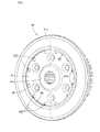
FIG. 5 is a perspective view as viewed from the left side of a clutch centre; -
FIG. 6 is a perspective view as viewed from the right side of the clutch centre; -
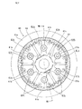
FIG. 7 is a right view of the clutch centre; and -
FIG. 8 is a sectional view of the clutch centre (taken along line VIII-VIII inFIG. 7 ). - A currently preferred embodiment of the present invention will be described below based on
FIGS. 1 to 8 . -
FIG. 1 is a right side view of an internal combustion engine E from which a case cover has been removed.FIG. 2 is a cross-sectional development view of the internal combustion engine taken along line II-II inFIG. 1 . - The internal combustion engine E is a water-cooled, single-cylinder, four-stroke internal combustion engine, which may be mounted in a motorcycle.
- In the present description, terms such as "front", "rear", "left", and "right" should be interpreted with reference to the motorcycle, with the straight-running direction of the motorcycle being defined as the front direction.
- A
crankcase 11 that rotatably supports acrankshaft 20 extending along the left-right direction (which is also the lateral or widthwise direction of the vehicle) forms a crank chamber 11c in which thecrankshaft 20 is disposed. In addition, atransmission chamber 11 m that is partitioned by a partition wall and houses a transmission M is formed on the rear side of the crank chamber 11 c. - The single-cylinder, four-stroke internal combustion engine E has, over the crank chamber 11c of the
crankcase 11, an engine main body composed of acylinder block 12 having onecylinder 12a, acylinder head 13 joined to the upper part of thecylinder block 12 by stud bolts with the intermediary of a gasket, and acylinder head cover 14 joined to the upper part of thecylinder head 13. - The
cylinder block 12, thecylinder head 13, and thecylinder head cover 14 stacked over thecrankcase 11 project upward with a posture such that they are tilted slightly forward from thecrankcase 11. - In the
transmission chamber 11 m of thecrankcase 11, amain shaft 21 and acountershaft 22 of the transmission M are disposed, and extend parallel to thecrankshaft 20. - The
crankcase 11 is formed from aleft crankcase 11 L and aright crankcase 11 R, which abut along a plane that includes a cylinder axis line Lc and which is orthogonal to thecrankshaft 20. Theleft crankcase 11 L and theright crankcase 11 R are joined to each other in a state in which their joining surfaces are mated with each other. - The lower part of the
cylinder 12a of thecylinder block 12 is fitted into a circular opening formed above the crank chamber 11 c at the join of the left andright crankcases piston 15 is fitted into a cylinder bore of thecylinder 12a in such a manner as to be capable of reciprocating sliding. - The
piston 15 is connected to thecrankshaft 20 by a connectingrod 16 having a smaller end part ("little end") journaled by a piston pin 15p of thepiston 15 and a larger end part ("big end") journaled by acrankpin 20p of thecrankshaft 20. Therefore, a crank mechanism is formed. - A
left shaft body 20L protruding leftwards beyond a left main bearing 25 in thecrankshaft 20 penetrates a chain chamber and furthermore penetrates an opening of the left sidewall of theleft crankcase 11 L. A drive cam chain sprocket 20cs is formed at the part within the chain chamber, and anouter rotor 26r of anAC generator 26 is fitted at the left end of theleft shaft body 20L. - A
left side cover 17 that seals the opening of the left sidewall of theleft crankcase 11 L covers theAC generator 26 and supports aninner stator 26s of theAC generator 26. - On the other hand, the
right shaft body 20R protrudes rightwards beyond a right main bearing 25 of theright crankcase 11 R in thecrankshaft 20, and a starter drivengear 27 and aprimary drive gear 28 are fitted to theright shaft body 20R in that order from the side of the main bearing 25 and are fastened by a flangedbolt 29 with the intermediary of awasher 29w (seeFIG. 2 ). - The transmission M disposed in the
transmission chamber 11 m on the rear side of the crank chamber 11 c includes themain shaft 21 and thecountershaft 22 provided with amain gear group 21 g and acounter gear group 22g, respectively, and a gear change mechanism with a shift drum and a shift fork (not shown) operated by a gearshift operation mechanism. - The
main shaft 21 is behind and obliquely above thecrankshaft 20 and is rotatably journaled by the left andright crankcases bearings 30. A multi-plate friction clutch C is provided at the part protruding rightwards beyond the right bearing 30 in themain shaft 21. - The
countershaft 22 is behind and obliquely below themain shaft 21 and is rotatably journaled by the left andright crankcases bearings 23. Thecountershaft 22 penetrates leftwards beyond the left bearing 23 and protrudes to the outside to serve as an output shaft, with adrive chain sprocket 24 being fitted to the protruding left end of thecountershaft 22. - A
drive chain 24c wound around thedrive chain sprocket 24 is also wound around a driven chain sprocket (not shown) on the rear wheel, and power is thus transmitted to the rear wheel. - The right side surface of the
right crankcase 11 R is covered by aright crankcase cover 18, and aclutch cover 19 that seals an opening which the multi-plate friction clutch C faces in theright crankcase cover 18 covers the right side of the multi-plate friction clutch C. - A
shaft hole 21 h is formed along the shaft core of themain shaft 21 and aclutch actuating rod 31 is inserted therein. - The
clutch actuating rod 31 is slidably supported at left and right parts of theshaft hole 21 h, which parts have a reduced diameter, and is moved rightwards (in the axial direction) by actuation of aclutch cam 32 that acts on the left end. - Oil discharged from a scavenge pump is supplied to the
shaft hole 21 h. - Referring to
FIGS. 3 and4 , asleeve member 40 is fitted to the radial outside of themain shaft 21 in such a manner as to come into contact with the inner race of the right bearing 30 from the right side, and a primary drivengear 42 is rotatably journaled by thesleeve member 40 with the intermediary of aneedle bearing 41. - The primary driven
gear 42 meshes with theprimary drive gear 28 fitted to thecrankshaft 20. - An oil
pump drive sprocket 43 is journaled on thesleeve member 40 and is in engagement with the left end of a centralcylindrical boss part 42c fitted radially outwardly of theneedle bearing 41 in the primary drivengear 42. - In the right end surface of the central
cylindrical boss part 42c of the primary drivengear 42, plural oil grooves 42cv are formed extending in the radial direction. - A clutch outer 50 in the multi-plate friction clutch C is formed with a bottomed cylindrical shape (a bowl shape), with an outer
bottom wall part 51 rotatably journaled by themain shaft 21 and an outercylindrical part 52 extending rightwards in the axial direction in a cylindrical shape from the peripheral edge of the outerbottom wall part 51. The outerbottom wall part 51 of this clutch outer 50 is supported so as to be in contact with a disc part of the primary drivengear 42 and is journaled by the centralcylindrical boss part 42c of the primary drivengear 42. - Furthermore, a
damper rubber 44, which is press-fitted to the outer circumference of a holdingboss part 51 b protruding from the outer surface of the outerbottom wall part 51, is fitted into a circular hole 42h formed in the disc part of the primary drivengear 42, and absorbs drastic torque variation between the primary drivengear 42 and the clutch outer 50. - Therefore, the rotation of the
crankshaft 20 is transmitted to the clutch outer 50 of the multi-plate friction clutch C via the meshing between theprimary drive gear 28 and the primary drivengear 42 and via thedamper rubber 44. - A
clutch centre 60 in the multi-plate friction clutch C includes a centrebottom wall part 61 that faces the inner surface of the outerbottom wall part 51 and is journaled by themain shaft 21, and a centrecylindrical part 62 extending in a cylindrical shape from the centrebottom wall part 61 away from the outer bottom wall part 51 (rightwards). - A central
cylindrical boss part 61 c of the centrebottom wall part 61 of theclutch centre 60 is spline-fitted to themain shaft 21. Therefore, the centrebottom wall part 61 is journaled with its relative rotation restricted. - A male screw is formed at the right end part of the
main shaft 21 and spline grooves are formed across a certain distance on the left side of the male screw. The centralcylindrical boss part 61 c of the centrebottom wall part 61 is fitted to the spline grooves with awasher 45 set between the centralcylindrical boss part 61c and an end surface of thesleeve member 40. Furthermore, anut member 48 is screwed to the male screw, with an interveningmetal piece 46 and awasher 47 located between thenut member 48 and the centralcylindrical boss part 61 c to secure the centralcylindrical boss part 61c (and the sleeve member 40) between thenut member 48 and the inner race of thebearing 30. Therefore, theclutch centre 60 is fixed at a predetermined position on themain shaft 21. - When the
clutch centre 60 is fixed at the predetermined position on themain shaft 21, the centrecylindrical part 62 of theclutch centre 60 is located inside the outercylindrical part 52, concentric with the outercylindrical part 52 and separated therefrom by a predetermined distance. - The outer diameter of the
washer 45, which is located between the end surface of thesleeve member 40 and the centralcylindrical boss part 61c of the centrebottom wall part 61, is slightly larger than the outer diameter of the centralcylindrical boss part 42c of the primary drivengear 42. Furthermore, thewasher 45 is close to the right end surface of the centralcylindrical boss part 42c, in which the oil grooves 42cv are formed, and theneedle bearing 41. Therefore, thewasher 45 allows smooth relative rotation between the primary drivengear 42 and theclutch centre 60 at the outer periphery of thesleeve member 40, which rotates integrally with themain shaft 21. - An
outer ring protrusion 55 projects in a flattened cylindrical shape from the position of a circular ring having a diameter slightly larger than the outer diameter of thewasher 45 on the inner surface (right side surface) of the outerbottom wall part 51 of the clutch outer 50. - The
outer ring protrusion 55 protrudes rightwards from the outerbottom wall part 51 beyond thewasher 45 and surrounds thewasher 45. Therefore, the axial position of theouter ring protrusion 55 overlaps with that of the right end of the centralcylindrical boss part 42c (right opening end part of the gap in which theneedle bearing 41 is interposed). - The outer circumferential surface of the
outer ring protrusion 55 is tapered and anoil thrower groove 56 is formed into a ring shape near aprotrusion end 55e of theouter ring protrusion 55 with this outer circumferential tapered surface. - Referring to
FIGS. 3 to 8 , in theclutch centre 60, plural communication holes 61 h are formed in the centrebottom wall part 61 at an equal distance from the axial centre across the circumferential direction, and allow the outer surface side and inner surface side of the centrebottom wall part 61 to communicate with each other. - The inner circumferential surface of the centre
cylindrical part 62 protruding from the inner surface of the centrebottom wall part 61 is located radially outside relative to the plural communication holes 61 h existing at the equal distance from the axial centre. Thus, the communication holes 61 h allow the outer surface side of the centrebottom wall part 61 to communicate with the inside of the centrecylindrical part 62 as well as the inner surface side of the centrebottom wall part 61. - A
centre ring protrusion 65 projects in a flattened cylindrical shape on the outer surface of the centrebottom wall part 61, and is formed at substantially the same radial position as the plural communication holes 61 h. - A
ring recess 66 opened toward the axial centre (indicated by a scattered-dot pattern inFIG. 5 ) is formed in a ring shape in the inner circumferential surface of thecentre ring protrusion 65. The communication holes 61 h are open so as to face thering recess 66. - When the clutch outer 50 and the
clutch centre 60 are assembled to themain shaft 21, theouter ring protrusion 55 protruding from the inner surface of the outerbottom wall part 51 of the clutch outer 50 is radially inwards of thecentre ring protrusion 65 protruding from the outer surface of the centrebottom wall part 61 of theclutch centre 60 and projects to the axial position of thering recess 66 of thecentre ring protrusion 65. - That is, the
protrusion end 55e of theouter ring protrusion 55 and thering recess 66 of thecentre ring protrusion 65 are in such a positional relationship as to be located at the same axial position, with theprotrusion end 55e radially inside of the ring recess 66 (as best shown inFIG. 4 ). - In the centre
cylindrical part 62 of theclutch centre 60, pluralsmall holes 62h that allow the inner circumferential side and outer circumferential side of the centrecylindrical part 62 to communicate with each other are drilled. - In the centre
bottom wall part 61, at positions at an equal distance from the axial centre and on a circular ring with a smaller diameter than the circular ring on which the plural communication holes 61 h are arranged, sixcylindrical boss parts 61 b are so formed as to protrude toward the axially outside (right side) to a large extent at equal intervals in the circumferential direction. -
Plural friction plates 71 and pluralclutch plates 72 are alternately inserted and fitted in a ring-shaped space between the outercylindrical part 52 and the centrecylindrical part 62, which concentrically overlap with each other. - Plural outer circumferential protrusions formed at the outer circumferential edges of the
friction plates 71 slidably engage withgrooves 52v that are made in the inner circumferential surface of the outercylindrical part 52 along the axial direction and formed as plural grooves in the circumferential direction. Thus, thefriction plates 71 rotate together with the clutch outer 50. - Furthermore, plural inner circumferential protrusions formed at the inner circumferential edges of the
clutch plates 72 slidably engage withgrooves 62v that are made in the outer circumferential surface of the centrecylindrical part 62 along the axial direction and formed as plural grooves in the circumferential direction. Thus, theclutch plates 72 rotate together with theclutch centre 60. - On the back side (left side) of the ring space between the outer
cylindrical part 52 and the centrecylindrical part 62, in which thefriction plates 71 and theclutch plates 72 are inserted and fitted, aperipheral part 61 a of the centrebottom wall part 61 of theclutch centre 60 is located and opposed to thefriction plate 71 inserted and fitted at the backmost position. - A
pressure plate 80 presses theplural friction plates 71 and the pluralclutch plates 72 alternately inserted and fitted by sandwiching them with theperipheral part 61 a of the centrebottom wall part 61. - The
pressure plate 80 has a shape of a slightly dished circular disc and aperipheral part 80a thereof sandwiches, from the right side, theplural friction plates 71 and the pluralclutch plates 72 alternately overlapping with each other with theperipheral part 61 a of the centrebottom wall part 61. - A
central boss part 80c of thepressure plate 80 is pressed by theclutch actuating rod 31, thereby operating thepressure plate 80. - A
cap member 33 at the tip (right end) of theclutch actuating rod 31 protrudes from an opening at a shaft end of themain shaft 21 and forms aflange part 33f. Thisflange part 33f faces aring side plate 35 made to abut against thecentral boss part 80c of thepressure plate 80 and athrust bearing 34 is arranged therebetween. - At radial positions between the
central boss part 80c and theperipheral part 80a of thepressure plate 80, large-diametercylindrical boss parts 80b that each correspond to a respective one of the sixcylindrical boss parts 61 b protruding from the centrebottom wall part 61 of theclutch centre 60 and have a larger diameter than thecylindrical boss parts 61 b are formed, so as to protrude toward the axially inner side (left side) to a large extent and cover the respectivecylindrical boss parts 61 b. - A female screw thread is formed in the tip-side inner circumferential surface of the
cylindrical boss part 61 b of theclutch centre 60 and aflanged bolt 75 is screwed into this thread. - A
clutch spring 76 is compressed and interposed between a tip bending part 80bb, which is bent inward at the tip of the large-diametercylindrical boss part 80b of thepressure plate 80, and the flange part of theflanged bolt 75 screwed to thecylindrical boss part 61 b of theclutch centre 60. - Therefore, a biasing force acts on the
pressure plate 80 toward the axially inner side (left side) due to the spring force of theclutch spring 76, and theperipheral part 80a of thepressure plate 80 clamps thefriction plates 71 and theclutch plates 72 alternately overlapped with each other with theperipheral part 61 a of the centrebottom wall part 61. This provides a clutch-connected state in which the rotation of the clutch outer 50 is transmitted to theclutch centre 60 via thefriction plates 71 and theclutch plates 72 brought into pressure contact with each other. - When the
clutch actuating rod 31 is moved right by operation of theclutch cam 32, thepressure plate 80 is pressed via thecap member 33 and thethrust bearing 34 and moves right against the biasing force of theclutch spring 76. This can provide a clutch-disconnected state in which the clamping of thefriction plates 71 and theclutch plates 72 between thepressure plate 80 and theperipheral part 61 a of the centrebottom wall part 61 is released, and thus rotation of the clutch outer 50 is not transmitted to theclutch centre 60. - As shown by a dotted arrow in
FIG. 4 , when the internal combustion engine E is operating and thecrankshaft 20 is rotating, oil introduced into theshaft hole 21 h of themain shaft 21 through driving of a scavenge pump flows into abranch hole 21 hh branching from theshaft hole 21 h in the radial direction and is supplied to the respective journaling parts of themain gear group 21g. In addition, the oil is also supplied to theneedle bearing 41 as the journaling part of the primary drivengear 42, which supports the clutch outer 50. - The
sleeve member 40 also has ahole 40h communicating with thebranch hole 21 hh and guiding the oil to the needle bearing 41 (seeFIG. 4 ). - Referring to the dotted arrow in
FIG. 4 , the oil supplied to theneedle bearing 41 lubricates theneedle bearing 41. Thereafter, the oil leaves from the right opening of the gap in which theneedle bearing 41 is interposed between thesleeve member 40 and the centralcylindrical boss part 42c of the primary drivengear 42, which rotates relative to thesleeve member 40, and passes through the oil grooves 42cv formed between the right end surface of the centralcylindrical boss part 42c and thewasher 45. Then, the oil leaks and flows out to the inner circumferential surface of theouter ring protrusion 55 protruding on the outerbottom wall part 51 of the clutch outer 50, which rotates together with the primary drivengear 42. - The
outer ring protrusion 55 is located axially so as to overlap with the right opening end part of the gap in which theneedle bearing 41 is interposed. Thus, the oil that has passed from theneedle bearing 41 through the oil grooves 42cv to leak efficiently flows out to the inner circumferential surface of theouter ring protrusion 55. - The oil that flowed out to the inner circumferential surface of the rotating
outer ring protrusion 55 flows around theprotrusion end 55e of theouter ring protrusion 55 to the outer circumferential surface side. However, because theoil thrower groove 56 exists, little oil goes beyond theoil thrower groove 56 and flows along the inner surface of the outerbottom wall part 51, and most of the oil instead flies from theprotrusion end 55e of theouter ring protrusion 55 in the centrifugal direction between the outerbottom wall part 51 and the centrebottom wall part 61 due to the centrifugal force of the rotating clutch outer 50. - The
outer ring protrusion 55 protruding from the inner surface of the outerbottom wall part 51 protrudes to the axial position of thering recess 66 of thecentre ring protrusion 65. Therefore, theprotrusion end 55e of theouter ring protrusion 55 and thering recess 66 of thecentre ring protrusion 65 are in such a positional relationship as to be located at the same axial position, with thering recess 66 radially outside theprotrusion end 55e. Therefore, as shown by dashed arrows inFIGS. 3 and4 , the oil that flies in the centrifugal direction from theprotrusion end 55e of theouter ring protrusion 55 is efficiently received by thering recess 66 opened toward the axial centre in thecentre ring protrusion 65. - Part of the oil that flies from the
protrusion end 55e of theouter ring protrusion 55 adheres to the outer surface of the centrebottom wall part 61. However, when theclutch centre 60 rotates, the oil flows in the centrifugal direction along the outer surface of the centrebottom wall part 61 and enters thering recess 66 of thecentre ring protrusion 65. - Therefore, the oil that has lubricated the
needle bearing 41, which journals the primary drivengear 42 and the clutch outer 50, flows out to the space between the outerbottom wall part 51 and the centrebottom wall part 61. Then, the oil flies in the centrifugal direction from theprotrusion end 55e of theouter ring protrusion 55 and most of the oil enters thering recess 66 of thecentre ring protrusion 65 and accumulates therein. - The oil accumulated in the
ring recess 66 of thecentre ring protrusion 65 passes through the plural communication holes 61 h, which are open so as to face thering recess 66, and flows from the outer surface side of the centrebottom wall part 61 to the inner surface side to flow out to the inner circumferential surface side of the centrecylindrical part 62. - Because the plural
small holes 62h are drilled in the centrecylindrical part 62, the oil that has flowed out to the inner circumferential surface side of the centrecylindrical part 62 can pass through the pluralsmall holes 62h to be supplied to thefriction plates 71 and theclutch plates 72 alternately overlapped with each other on the outer circumferential surface side of the centrecylindrical part 62. - As described above, in the present multi-plate friction clutch C, the
ring recess 66 of thecentre ring protrusion 65 of theclutch centre 60 efficiently receives the oil that has lubricated theneedle bearing 41, which journals the primary drivengear 42 and the clutch outer 50, and most of the oil is accumulated in thering recess 66. This accumulated oil passes through the communication holes 61 h and thesmall holes 62h to be supplied to thefriction plates 71 and theclutch plates 72. Therefore, lubrication sites such as thefriction plates 71 and theclutch plates 72 in the multi-plate friction clutch can be lubricated by being sufficiently supplied with the oil efficiently, so that the multi-plate friction clutch C can be smoothly connected and disconnected. - The oil is supplied to the
needle bearing 41, which journals the clutch outer 50, by a scavenge pump. Therefore, the hydraulic pressure is lower than that achieved with a feed pump, and the amount of supply is not so large. However, the oil can be efficiently recovered to be guided to the multi-plate friction clutch C in the above-described manner and lubrication sites can be sufficiently lubricated. - If the oil is supplied by a feed pump, the capacity of the feed pump can be lowered.
Claims (5)
- A multi-plate friction clutch comprising:a clutch outer (50) which has a bottomed cylindrical shape and in which an outer cylindrical part (52) extends along an axial direction from an outer circumferential edge of an outer bottom wall part (51) whose centre is journaled by a rotation shaft (21) with intermediary of a bearing (41);a clutch centre (60) in which a centre cylindrical part (62) is formed inside the outer cylindrical part (52) and extends from a centre bottom wall part (61) whose centre is journaled by the rotation shaft (21) with restriction of relative rotation, the centre cylindrical part (62) extending away from the outer bottom wall part (51), and the centre bottom wall part (61) facing an inner surface of the outer bottom wall part (51) and having a plurality of communication holes (61 h) formed at an equal distance from an axial centre;a plurality of friction plates (71) engaging with the outer cylindrical part (52) and a plurality of clutch plates (72) engaging with the centre cylindrical part (62) which are arranged alternately in the axial direction overlapping with each other in a ring-shaped space between the outer cylindrical part (52) and the centre cylindrical part (62); anda pressure plate (80) that sandwiches the friction plates (71) and the clutch plates (72) with the centre bottom wall part (61), and presses the friction plates (71) and the clutch plates (72) by a biasing force of a clutch spring (76);the multi-plate friction clutch being characterized in thata centre ring protrusion (65), projecting in a cylindrical shape from an outer surface of the centre bottom wall part (61), is formed at substantially the same radial position as the plurality of communication holes (61 h),a ring recess (66), open toward the axial centre, is formed in an inner circumferential surface of the centre ring protrusion (65), andthe communication holes (61 h) are open so as to face the ring recess (66).
- The multi-plate friction clutch according to claim 1, characterized in that
an inner circumferential surface of the centre cylindrical part (62) is formed radially outside relative to the communication holes (61 h), and
a plurality of small holes (62h) that allow an inner circumferential surface side and an outer circumferential surface side of the centre cylindrical part (62) to communicate with each other are formed in the centre cylindrical part (62). - The multi-plate friction clutch according to claim 1 or claim 2, characterized in that
an outer ring protrusion (55), projecting in a cylindrical shape from the inner surface of the outer bottom wall part (51), is formed radially inside relative to the centre ring protrusion (65), and
the outer ring protrusion (55) protrudes to an axial position of the ring recess (66). - The multi-plate friction clutch according to claim 3, characterized in that
an oil thrower groove (56) is formed in a ring shape in an outer circumferential surface of the outer ring protrusion (55). - The multi-plate friction clutch according to claim 3 or claim 4, characterized in that
an axial position of the outer ring protrusion (55) overlaps with an axial position of an opening end part of a gap in which the bearing (41) to journal the outer bottom wall part (51) is interposed.
Applications Claiming Priority (1)
| Application Number | Priority Date | Filing Date | Title |
|---|---|---|---|
| JP2014053617A JP6113681B2 (en) | 2014-03-17 | 2014-03-17 | Multi-plate friction clutch |
Publications (2)
| Publication Number | Publication Date |
|---|---|
| EP2921735A1 true EP2921735A1 (en) | 2015-09-23 |
| EP2921735B1 EP2921735B1 (en) | 2017-02-01 |
Family
ID=52633175
Family Applications (1)
| Application Number | Title | Priority Date | Filing Date |
|---|---|---|---|
| EP15158764.9A Not-in-force EP2921735B1 (en) | 2014-03-17 | 2015-03-12 | Multi-plate friction clutch |
Country Status (5)
| Country | Link |
|---|---|
| US (1) | US9534639B2 (en) |
| EP (1) | EP2921735B1 (en) |
| JP (1) | JP6113681B2 (en) |
| AU (1) | AU2015200927B2 (en) |
| ES (1) | ES2617074T3 (en) |
Cited By (1)
| Publication number | Priority date | Publication date | Assignee | Title |
|---|---|---|---|---|
| IT201700031815A1 (en) * | 2017-03-22 | 2018-09-22 | Adler Spa | Clutch, in particular clutch for motorcycles, and relative mounting method |
Families Citing this family (7)
| Publication number | Priority date | Publication date | Assignee | Title |
|---|---|---|---|---|
| JP6463905B2 (en) * | 2014-05-29 | 2019-02-06 | 川崎重工業株式会社 | Clutch damper structure |
| US10337566B2 (en) | 2016-01-19 | 2019-07-02 | Tubeworks, Inc. | Low loss direct point wet clutch fluid wall system |
| ITUA20161890A1 (en) * | 2016-03-22 | 2017-09-22 | Dana Graziano Srl | Friction clutch for vehicle transmission. |
| DE102016213657B4 (en) * | 2016-07-26 | 2018-09-27 | Schaeffler Technologies AG & Co. KG | Coupling device for a drive train of a vehicle |
| JP7523548B2 (en) * | 2020-08-06 | 2024-07-26 | 株式会社エフ・シー・シー | Power transmission |
| CN117545937A (en) * | 2021-06-23 | 2024-02-09 | Gkn汽车有限公司 | Fluid guiding device for friction plate clutch and clutch unit with fluid guiding device |
| JP7434641B1 (en) | 2022-09-28 | 2024-02-20 | 株式会社エフ・シー・シー | Clutch devices and motorcycles |
Citations (6)
| Publication number | Priority date | Publication date | Assignee | Title |
|---|---|---|---|---|
| JPS55132531U (en) * | 1979-03-15 | 1980-09-19 | ||
| GB1582128A (en) * | 1976-07-08 | 1980-12-31 | Gkn Transmissions Ltd | Clutches |
| JPS60234126A (en) | 1984-05-07 | 1985-11-20 | Yamaha Motor Co Ltd | Multi-disc frictional clutch |
| DE102007023953A1 (en) * | 2007-05-23 | 2008-11-27 | Zf Friedrichshafen Ag | Planetary gear with a multi-plate clutch or a multi-disc brake |
| JP2009270701A (en) * | 2008-05-12 | 2009-11-19 | Yamaha Motor Co Ltd | Engine and small vehicle |
| US20150057123A1 (en) * | 2013-08-23 | 2015-02-26 | American Axle & Mfg Inc | Optimized outer clutch housing for reduced spin loss, improved oil flow and improved clutch durability |
Family Cites Families (9)
| Publication number | Priority date | Publication date | Assignee | Title |
|---|---|---|---|---|
| JPS54142448A (en) * | 1978-04-27 | 1979-11-06 | Suzuki Motor Co Ltd | Lubricating device of multiple plate clutch |
| JPS58196322A (en) * | 1982-05-13 | 1983-11-15 | Asahi Glass Co Ltd | Shaft coupling |
| JPS6217428A (en) * | 1985-07-15 | 1987-01-26 | Yamaha Motor Co Ltd | Cushion ring of wet type multiple disc clutch |
| CN100476270C (en) * | 2003-10-29 | 2009-04-08 | 株式会社小松制作所 | Non-contact type oil sealing mechanism of rotating shaft |
| JP5503320B2 (en) * | 2010-02-09 | 2014-05-28 | 本田技研工業株式会社 | Clutch device |
| JP5905763B2 (en) * | 2012-03-29 | 2016-04-20 | 本田技研工業株式会社 | Clutch device |
| JP5882103B2 (en) * | 2012-03-29 | 2016-03-09 | 本田技研工業株式会社 | Clutch device |
| US9157488B2 (en) * | 2012-03-29 | 2015-10-13 | Honda Motor Co., Ltd. | Clutch apparatus |
| JP5905762B2 (en) * | 2012-03-29 | 2016-04-20 | 本田技研工業株式会社 | Clutch device |
-
2014
- 2014-03-17 JP JP2014053617A patent/JP6113681B2/en active Active
-
2015
- 2015-02-24 AU AU2015200927A patent/AU2015200927B2/en not_active Ceased
- 2015-03-12 EP EP15158764.9A patent/EP2921735B1/en not_active Not-in-force
- 2015-03-12 US US14/645,506 patent/US9534639B2/en active Active
- 2015-03-12 ES ES15158764.9T patent/ES2617074T3/en active Active
Patent Citations (6)
| Publication number | Priority date | Publication date | Assignee | Title |
|---|---|---|---|---|
| GB1582128A (en) * | 1976-07-08 | 1980-12-31 | Gkn Transmissions Ltd | Clutches |
| JPS55132531U (en) * | 1979-03-15 | 1980-09-19 | ||
| JPS60234126A (en) | 1984-05-07 | 1985-11-20 | Yamaha Motor Co Ltd | Multi-disc frictional clutch |
| DE102007023953A1 (en) * | 2007-05-23 | 2008-11-27 | Zf Friedrichshafen Ag | Planetary gear with a multi-plate clutch or a multi-disc brake |
| JP2009270701A (en) * | 2008-05-12 | 2009-11-19 | Yamaha Motor Co Ltd | Engine and small vehicle |
| US20150057123A1 (en) * | 2013-08-23 | 2015-02-26 | American Axle & Mfg Inc | Optimized outer clutch housing for reduced spin loss, improved oil flow and improved clutch durability |
Cited By (3)
| Publication number | Priority date | Publication date | Assignee | Title |
|---|---|---|---|---|
| IT201700031815A1 (en) * | 2017-03-22 | 2018-09-22 | Adler Spa | Clutch, in particular clutch for motorcycles, and relative mounting method |
| WO2018172176A1 (en) * | 2017-03-22 | 2018-09-27 | Adler S.P.A. | Clutch, in particular clutch for motorcycles, and related mounting method |
| CN110709616A (en) * | 2017-03-22 | 2020-01-17 | 艾德勒股份有限公司 | Clutches, especially for motorcycles, and related installation methods |
Also Published As
| Publication number | Publication date |
|---|---|
| US9534639B2 (en) | 2017-01-03 |
| US20150260236A1 (en) | 2015-09-17 |
| AU2015200927A1 (en) | 2015-10-01 |
| EP2921735B1 (en) | 2017-02-01 |
| JP6113681B2 (en) | 2017-04-12 |
| AU2015200927B2 (en) | 2016-08-11 |
| ES2617074T3 (en) | 2017-06-15 |
| JP2015175472A (en) | 2015-10-05 |
Similar Documents
| Publication | Publication Date | Title |
|---|---|---|
| EP2921735B1 (en) | Multi-plate friction clutch | |
| EP3300227B1 (en) | Electric generator cooling structure for internal combustion engine | |
| US20080096718A1 (en) | Engine | |
| JP5418173B2 (en) | Dry clutch | |
| US10539195B2 (en) | Oil supply structure of clutch device | |
| US10830285B2 (en) | Pressure plate and clutch device | |
| WO2016017369A1 (en) | Hybrid drive device | |
| US8147370B2 (en) | Power unit for motorcycle | |
| US20080081714A1 (en) | Power transmission device | |
| US8512181B2 (en) | Power unit for small vehicle | |
| US11525488B2 (en) | Automatic transmission | |
| US9695883B2 (en) | Clutch device | |
| JP5616667B2 (en) | Oil supply structure of power transmission mechanism | |
| JP2003322177A (en) | Multi-plate automatic centrifugal clutch device | |
| JP7331574B2 (en) | clutch device | |
| US20080078639A1 (en) | Power transmission device | |
| JP2022135638A (en) | clutch device | |
| US8939257B2 (en) | Power train mechanism including a surrounding member | |
| US20220154785A1 (en) | Automatic transmission | |
| EP3617556A1 (en) | Liquid path system | |
| US12140190B2 (en) | Multiple-disc friction clutch | |
| JP2019190469A (en) | Automatic transmission | |
| CN101152840A (en) | transmission | |
| JP6708051B2 (en) | Engine bearing support structure | |
| JP2017133555A (en) | Clutch lubrication structure and engine equipped with the same |
Legal Events
| Date | Code | Title | Description |
|---|---|---|---|
| PUAI | Public reference made under article 153(3) epc to a published international application that has entered the european phase |
Free format text: ORIGINAL CODE: 0009012 |
|
| 17P | Request for examination filed |
Effective date: 20150312 |
|
| AK | Designated contracting states |
Kind code of ref document: A1 Designated state(s): AL AT BE BG CH CY CZ DE DK EE ES FI FR GB GR HR HU IE IS IT LI LT LU LV MC MK MT NL NO PL PT RO RS SE SI SK SM TR |
|
| AX | Request for extension of the european patent |
Extension state: BA ME |
|
| RIC1 | Information provided on ipc code assigned before grant |
Ipc: F16D 13/52 20060101ALI20160706BHEP Ipc: F16D 13/56 20060101AFI20160706BHEP Ipc: F16D 13/72 20060101ALI20160706BHEP |
|
| GRAP | Despatch of communication of intention to grant a patent |
Free format text: ORIGINAL CODE: EPIDOSNIGR1 |
|
| INTG | Intention to grant announced |
Effective date: 20160818 |
|
| GRAS | Grant fee paid |
Free format text: ORIGINAL CODE: EPIDOSNIGR3 |
|
| GRAA | (expected) grant |
Free format text: ORIGINAL CODE: 0009210 |
|
| AK | Designated contracting states |
Kind code of ref document: B1 Designated state(s): AL AT BE BG CH CY CZ DE DK EE ES FI FR GB GR HR HU IE IS IT LI LT LU LV MC MK MT NL NO PL PT RO RS SE SI SK SM TR |
|
| REG | Reference to a national code |
Ref country code: GB Ref legal event code: FG4D |
|
| REG | Reference to a national code |
Ref country code: FR Ref legal event code: PLFP Year of fee payment: 3 |
|
| REG | Reference to a national code |
Ref country code: CH Ref legal event code: EP Ref country code: AT Ref legal event code: REF Ref document number: 865861 Country of ref document: AT Kind code of ref document: T Effective date: 20170215 |
|
| REG | Reference to a national code |
Ref country code: IE Ref legal event code: FG4D |
|
| REG | Reference to a national code |
Ref country code: DE Ref legal event code: R096 Ref document number: 602015001378 Country of ref document: DE |
|
| REG | Reference to a national code |
Ref country code: NL Ref legal event code: MP Effective date: 20170201 |
|
| REG | Reference to a national code |
Ref country code: LT Ref legal event code: MG4D |
|
| REG | Reference to a national code |
Ref country code: ES Ref legal event code: FG2A Ref document number: 2617074 Country of ref document: ES Kind code of ref document: T3 Effective date: 20170615 Ref country code: AT Ref legal event code: MK05 Ref document number: 865861 Country of ref document: AT Kind code of ref document: T Effective date: 20170201 |
|
| PG25 | Lapsed in a contracting state [announced via postgrant information from national office to epo] |
Ref country code: NO Free format text: LAPSE BECAUSE OF FAILURE TO SUBMIT A TRANSLATION OF THE DESCRIPTION OR TO PAY THE FEE WITHIN THE PRESCRIBED TIME-LIMIT Effective date: 20170501 Ref country code: IS Free format text: LAPSE BECAUSE OF FAILURE TO SUBMIT A TRANSLATION OF THE DESCRIPTION OR TO PAY THE FEE WITHIN THE PRESCRIBED TIME-LIMIT Effective date: 20170601 Ref country code: GR Free format text: LAPSE BECAUSE OF FAILURE TO SUBMIT A TRANSLATION OF THE DESCRIPTION OR TO PAY THE FEE WITHIN THE PRESCRIBED TIME-LIMIT Effective date: 20170502 Ref country code: LT Free format text: LAPSE BECAUSE OF FAILURE TO SUBMIT A TRANSLATION OF THE DESCRIPTION OR TO PAY THE FEE WITHIN THE PRESCRIBED TIME-LIMIT Effective date: 20170201 Ref country code: FI Free format text: LAPSE BECAUSE OF FAILURE TO SUBMIT A TRANSLATION OF THE DESCRIPTION OR TO PAY THE FEE WITHIN THE PRESCRIBED TIME-LIMIT Effective date: 20170201 Ref country code: HR Free format text: LAPSE BECAUSE OF FAILURE TO SUBMIT A TRANSLATION OF THE DESCRIPTION OR TO PAY THE FEE WITHIN THE PRESCRIBED TIME-LIMIT Effective date: 20170201 |
|
| PG25 | Lapsed in a contracting state [announced via postgrant information from national office to epo] |
Ref country code: SE Free format text: LAPSE BECAUSE OF FAILURE TO SUBMIT A TRANSLATION OF THE DESCRIPTION OR TO PAY THE FEE WITHIN THE PRESCRIBED TIME-LIMIT Effective date: 20170201 Ref country code: BG Free format text: LAPSE BECAUSE OF FAILURE TO SUBMIT A TRANSLATION OF THE DESCRIPTION OR TO PAY THE FEE WITHIN THE PRESCRIBED TIME-LIMIT Effective date: 20170501 Ref country code: NL Free format text: LAPSE BECAUSE OF NON-PAYMENT OF DUE FEES Effective date: 20170201 Ref country code: LV Free format text: LAPSE BECAUSE OF FAILURE TO SUBMIT A TRANSLATION OF THE DESCRIPTION OR TO PAY THE FEE WITHIN THE PRESCRIBED TIME-LIMIT Effective date: 20170201 Ref country code: PT Free format text: LAPSE BECAUSE OF FAILURE TO SUBMIT A TRANSLATION OF THE DESCRIPTION OR TO PAY THE FEE WITHIN THE PRESCRIBED TIME-LIMIT Effective date: 20170601 Ref country code: PL Free format text: LAPSE BECAUSE OF FAILURE TO SUBMIT A TRANSLATION OF THE DESCRIPTION OR TO PAY THE FEE WITHIN THE PRESCRIBED TIME-LIMIT Effective date: 20170201 Ref country code: RS Free format text: LAPSE BECAUSE OF FAILURE TO SUBMIT A TRANSLATION OF THE DESCRIPTION OR TO PAY THE FEE WITHIN THE PRESCRIBED TIME-LIMIT Effective date: 20170201 Ref country code: AT Free format text: LAPSE BECAUSE OF FAILURE TO SUBMIT A TRANSLATION OF THE DESCRIPTION OR TO PAY THE FEE WITHIN THE PRESCRIBED TIME-LIMIT Effective date: 20170201 |
|
| PG25 | Lapsed in a contracting state [announced via postgrant information from national office to epo] |
Ref country code: SK Free format text: LAPSE BECAUSE OF FAILURE TO SUBMIT A TRANSLATION OF THE DESCRIPTION OR TO PAY THE FEE WITHIN THE PRESCRIBED TIME-LIMIT Effective date: 20170201 Ref country code: CZ Free format text: LAPSE BECAUSE OF FAILURE TO SUBMIT A TRANSLATION OF THE DESCRIPTION OR TO PAY THE FEE WITHIN THE PRESCRIBED TIME-LIMIT Effective date: 20170201 Ref country code: EE Free format text: LAPSE BECAUSE OF FAILURE TO SUBMIT A TRANSLATION OF THE DESCRIPTION OR TO PAY THE FEE WITHIN THE PRESCRIBED TIME-LIMIT Effective date: 20170201 Ref country code: RO Free format text: LAPSE BECAUSE OF FAILURE TO SUBMIT A TRANSLATION OF THE DESCRIPTION OR TO PAY THE FEE WITHIN THE PRESCRIBED TIME-LIMIT Effective date: 20170201 |
|
| REG | Reference to a national code |
Ref country code: DE Ref legal event code: R097 Ref document number: 602015001378 Country of ref document: DE |
|
| PG25 | Lapsed in a contracting state [announced via postgrant information from national office to epo] |
Ref country code: DK Free format text: LAPSE BECAUSE OF FAILURE TO SUBMIT A TRANSLATION OF THE DESCRIPTION OR TO PAY THE FEE WITHIN THE PRESCRIBED TIME-LIMIT Effective date: 20170201 Ref country code: SM Free format text: LAPSE BECAUSE OF FAILURE TO SUBMIT A TRANSLATION OF THE DESCRIPTION OR TO PAY THE FEE WITHIN THE PRESCRIBED TIME-LIMIT Effective date: 20170201 Ref country code: MC Free format text: LAPSE BECAUSE OF FAILURE TO SUBMIT A TRANSLATION OF THE DESCRIPTION OR TO PAY THE FEE WITHIN THE PRESCRIBED TIME-LIMIT Effective date: 20170201 |
|
| PLBE | No opposition filed within time limit |
Free format text: ORIGINAL CODE: 0009261 |
|
| STAA | Information on the status of an ep patent application or granted ep patent |
Free format text: STATUS: NO OPPOSITION FILED WITHIN TIME LIMIT |
|
| REG | Reference to a national code |
Ref country code: IE Ref legal event code: MM4A |
|
| 26N | No opposition filed |
Effective date: 20171103 |
|
| PG25 | Lapsed in a contracting state [announced via postgrant information from national office to epo] |
Ref country code: LU Free format text: LAPSE BECAUSE OF NON-PAYMENT OF DUE FEES Effective date: 20170312 |
|
| REG | Reference to a national code |
Ref country code: FR Ref legal event code: PLFP Year of fee payment: 4 |
|
| PG25 | Lapsed in a contracting state [announced via postgrant information from national office to epo] |
Ref country code: SI Free format text: LAPSE BECAUSE OF FAILURE TO SUBMIT A TRANSLATION OF THE DESCRIPTION OR TO PAY THE FEE WITHIN THE PRESCRIBED TIME-LIMIT Effective date: 20170201 Ref country code: IE Free format text: LAPSE BECAUSE OF NON-PAYMENT OF DUE FEES Effective date: 20170312 |
|
| REG | Reference to a national code |
Ref country code: BE Ref legal event code: MM Effective date: 20170331 |
|
| PG25 | Lapsed in a contracting state [announced via postgrant information from national office to epo] |
Ref country code: BE Free format text: LAPSE BECAUSE OF NON-PAYMENT OF DUE FEES Effective date: 20170331 |
|
| PGFP | Annual fee paid to national office [announced via postgrant information from national office to epo] |
Ref country code: ES Payment date: 20180402 Year of fee payment: 4 |
|
| PG25 | Lapsed in a contracting state [announced via postgrant information from national office to epo] |
Ref country code: MT Free format text: LAPSE BECAUSE OF NON-PAYMENT OF DUE FEES Effective date: 20170312 |
|
| REG | Reference to a national code |
Ref country code: CH Ref legal event code: PL |
|
| PG25 | Lapsed in a contracting state [announced via postgrant information from national office to epo] |
Ref country code: CH Free format text: LAPSE BECAUSE OF NON-PAYMENT OF DUE FEES Effective date: 20180331 Ref country code: LI Free format text: LAPSE BECAUSE OF NON-PAYMENT OF DUE FEES Effective date: 20180331 |
|
| PGFP | Annual fee paid to national office [announced via postgrant information from national office to epo] |
Ref country code: FR Payment date: 20190213 Year of fee payment: 5 |
|
| PG25 | Lapsed in a contracting state [announced via postgrant information from national office to epo] |
Ref country code: HU Free format text: LAPSE BECAUSE OF FAILURE TO SUBMIT A TRANSLATION OF THE DESCRIPTION OR TO PAY THE FEE WITHIN THE PRESCRIBED TIME-LIMIT; INVALID AB INITIO Effective date: 20150312 |
|
| PG25 | Lapsed in a contracting state [announced via postgrant information from national office to epo] |
Ref country code: CY Free format text: LAPSE BECAUSE OF FAILURE TO SUBMIT A TRANSLATION OF THE DESCRIPTION OR TO PAY THE FEE WITHIN THE PRESCRIBED TIME-LIMIT Effective date: 20170201 |
|
| GBPC | Gb: european patent ceased through non-payment of renewal fee |
Effective date: 20190312 |
|
| PG25 | Lapsed in a contracting state [announced via postgrant information from national office to epo] |
Ref country code: MK Free format text: LAPSE BECAUSE OF FAILURE TO SUBMIT A TRANSLATION OF THE DESCRIPTION OR TO PAY THE FEE WITHIN THE PRESCRIBED TIME-LIMIT Effective date: 20170201 |
|
| REG | Reference to a national code |
Ref country code: DE Ref legal event code: R084 Ref document number: 602015001378 Country of ref document: DE |
|
| PG25 | Lapsed in a contracting state [announced via postgrant information from national office to epo] |
Ref country code: GB Free format text: LAPSE BECAUSE OF NON-PAYMENT OF DUE FEES Effective date: 20190312 |
|
| PG25 | Lapsed in a contracting state [announced via postgrant information from national office to epo] |
Ref country code: TR Free format text: LAPSE BECAUSE OF FAILURE TO SUBMIT A TRANSLATION OF THE DESCRIPTION OR TO PAY THE FEE WITHIN THE PRESCRIBED TIME-LIMIT Effective date: 20170201 |
|
| PGFP | Annual fee paid to national office [announced via postgrant information from national office to epo] |
Ref country code: IT Payment date: 20200221 Year of fee payment: 6 Ref country code: DE Payment date: 20200225 Year of fee payment: 6 |
|
| REG | Reference to a national code |
Ref country code: ES Ref legal event code: FD2A Effective date: 20200724 |
|
| PG25 | Lapsed in a contracting state [announced via postgrant information from national office to epo] |
Ref country code: AL Free format text: LAPSE BECAUSE OF FAILURE TO SUBMIT A TRANSLATION OF THE DESCRIPTION OR TO PAY THE FEE WITHIN THE PRESCRIBED TIME-LIMIT Effective date: 20170201 |
|
| PG25 | Lapsed in a contracting state [announced via postgrant information from national office to epo] |
Ref country code: ES Free format text: LAPSE BECAUSE OF NON-PAYMENT OF DUE FEES Effective date: 20190313 |
|
| PG25 | Lapsed in a contracting state [announced via postgrant information from national office to epo] |
Ref country code: FR Free format text: LAPSE BECAUSE OF NON-PAYMENT OF DUE FEES Effective date: 20200331 |
|
| REG | Reference to a national code |
Ref country code: DE Ref legal event code: R082 Ref document number: 602015001378 Country of ref document: DE |
|
| REG | Reference to a national code |
Ref country code: DE Ref legal event code: R119 Ref document number: 602015001378 Country of ref document: DE |
|
| PG25 | Lapsed in a contracting state [announced via postgrant information from national office to epo] |
Ref country code: DE Free format text: LAPSE BECAUSE OF NON-PAYMENT OF DUE FEES Effective date: 20211001 |
|
| PG25 | Lapsed in a contracting state [announced via postgrant information from national office to epo] |
Ref country code: IT Free format text: LAPSE BECAUSE OF NON-PAYMENT OF DUE FEES Effective date: 20210312 |