EP3601791B1 - Flanschsegment für ein windenergieanlagen-stahlturmringsegment und verfahren - Google Patents
Flanschsegment für ein windenergieanlagen-stahlturmringsegment und verfahren Download PDFInfo
- Publication number
- EP3601791B1 EP3601791B1 EP18712595.0A EP18712595A EP3601791B1 EP 3601791 B1 EP3601791 B1 EP 3601791B1 EP 18712595 A EP18712595 A EP 18712595A EP 3601791 B1 EP3601791 B1 EP 3601791B1
- Authority
- EP
- European Patent Office
- Prior art keywords
- flange
- segment
- wind turbine
- steel tower
- projection
- Prior art date
- Legal status (The legal status is an assumption and is not a legal conclusion. Google has not performed a legal analysis and makes no representation as to the accuracy of the status listed.)
- Active
Links
- 229910000831 Steel Inorganic materials 0.000 title claims description 110
- 239000010959 steel Substances 0.000 title claims description 110
- 238000000034 method Methods 0.000 title description 14
- 238000003466 welding Methods 0.000 claims description 17
- 238000004519 manufacturing process Methods 0.000 claims description 10
- 230000007704 transition Effects 0.000 claims description 9
- 238000003801 milling Methods 0.000 claims description 4
- 239000002994 raw material Substances 0.000 claims description 2
- 239000007787 solid Substances 0.000 claims description 2
- 230000002093 peripheral effect Effects 0.000 description 37
- 238000011161 development Methods 0.000 description 10
- 230000018109 developmental process Effects 0.000 description 10
- 239000000463 material Substances 0.000 description 10
- 230000008569 process Effects 0.000 description 8
- 230000008901 benefit Effects 0.000 description 6
- 238000009434 installation Methods 0.000 description 5
- 230000032258 transport Effects 0.000 description 4
- 239000004567 concrete Substances 0.000 description 3
- 238000010276 construction Methods 0.000 description 3
- 229910052782 aluminium Inorganic materials 0.000 description 2
- XAGFODPZIPBFFR-UHFFFAOYSA-N aluminium Chemical compound [Al] XAGFODPZIPBFFR-UHFFFAOYSA-N 0.000 description 2
- 230000013011 mating Effects 0.000 description 2
- 229910052751 metal Inorganic materials 0.000 description 2
- 239000002184 metal Substances 0.000 description 2
- 230000035939 shock Effects 0.000 description 2
- 235000016936 Dendrocalamus strictus Nutrition 0.000 description 1
- CWYNVVGOOAEACU-UHFFFAOYSA-N Fe2+ Chemical compound [Fe+2] CWYNVVGOOAEACU-UHFFFAOYSA-N 0.000 description 1
- 239000000654 additive Substances 0.000 description 1
- 230000000996 additive effect Effects 0.000 description 1
- 230000002411 adverse Effects 0.000 description 1
- 238000005452 bending Methods 0.000 description 1
- 230000015572 biosynthetic process Effects 0.000 description 1
- 238000005266 casting Methods 0.000 description 1
- 239000000919 ceramic Substances 0.000 description 1
- 238000009826 distribution Methods 0.000 description 1
- 238000007688 edging Methods 0.000 description 1
- 238000005516 engineering process Methods 0.000 description 1
- 239000000945 filler Substances 0.000 description 1
- 230000004927 fusion Effects 0.000 description 1
- 239000007789 gas Substances 0.000 description 1
- 238000005304 joining Methods 0.000 description 1
- 238000004021 metal welding Methods 0.000 description 1
- 150000002739 metals Chemical class 0.000 description 1
- 239000004033 plastic Substances 0.000 description 1
- 239000010935 stainless steel Substances 0.000 description 1
Images


Classifications
-
- F—MECHANICAL ENGINEERING; LIGHTING; HEATING; WEAPONS; BLASTING
- F03—MACHINES OR ENGINES FOR LIQUIDS; WIND, SPRING, OR WEIGHT MOTORS; PRODUCING MECHANICAL POWER OR A REACTIVE PROPULSIVE THRUST, NOT OTHERWISE PROVIDED FOR
- F03D—WIND MOTORS
- F03D13/00—Assembly, mounting or commissioning of wind motors; Arrangements specially adapted for transporting wind motor components
- F03D13/20—Arrangements for mounting or supporting wind motors; Masts or towers for wind motors
-
- E—FIXED CONSTRUCTIONS
- E04—BUILDING
- E04H—BUILDINGS OR LIKE STRUCTURES FOR PARTICULAR PURPOSES; SWIMMING OR SPLASH BATHS OR POOLS; MASTS; FENCING; TENTS OR CANOPIES, IN GENERAL
- E04H12/00—Towers; Masts or poles; Chimney stacks; Water-towers; Methods of erecting such structures
- E04H12/02—Structures made of specified materials
- E04H12/08—Structures made of specified materials of metal
- E04H12/085—Details of flanges for tubular masts
-
- F—MECHANICAL ENGINEERING; LIGHTING; HEATING; WEAPONS; BLASTING
- F05—INDEXING SCHEMES RELATING TO ENGINES OR PUMPS IN VARIOUS SUBCLASSES OF CLASSES F01-F04
- F05B—INDEXING SCHEME RELATING TO WIND, SPRING, WEIGHT, INERTIA OR LIKE MOTORS, TO MACHINES OR ENGINES FOR LIQUIDS COVERED BY SUBCLASSES F03B, F03D AND F03G
- F05B2230/00—Manufacture
- F05B2230/20—Manufacture essentially without removing material
- F05B2230/23—Manufacture essentially without removing material by permanently joining parts together
- F05B2230/232—Manufacture essentially without removing material by permanently joining parts together by welding
-
- F—MECHANICAL ENGINEERING; LIGHTING; HEATING; WEAPONS; BLASTING
- F05—INDEXING SCHEMES RELATING TO ENGINES OR PUMPS IN VARIOUS SUBCLASSES OF CLASSES F01-F04
- F05B—INDEXING SCHEME RELATING TO WIND, SPRING, WEIGHT, INERTIA OR LIKE MOTORS, TO MACHINES OR ENGINES FOR LIQUIDS COVERED BY SUBCLASSES F03B, F03D AND F03G
- F05B2240/00—Components
- F05B2240/90—Mounting on supporting structures or systems
- F05B2240/91—Mounting on supporting structures or systems on a stationary structure
- F05B2240/912—Mounting on supporting structures or systems on a stationary structure on a tower
-
- Y—GENERAL TAGGING OF NEW TECHNOLOGICAL DEVELOPMENTS; GENERAL TAGGING OF CROSS-SECTIONAL TECHNOLOGIES SPANNING OVER SEVERAL SECTIONS OF THE IPC; TECHNICAL SUBJECTS COVERED BY FORMER USPC CROSS-REFERENCE ART COLLECTIONS [XRACs] AND DIGESTS
- Y02—TECHNOLOGIES OR APPLICATIONS FOR MITIGATION OR ADAPTATION AGAINST CLIMATE CHANGE
- Y02E—REDUCTION OF GREENHOUSE GAS [GHG] EMISSIONS, RELATED TO ENERGY GENERATION, TRANSMISSION OR DISTRIBUTION
- Y02E10/00—Energy generation through renewable energy sources
- Y02E10/70—Wind energy
- Y02E10/72—Wind turbines with rotation axis in wind direction
-
- Y—GENERAL TAGGING OF NEW TECHNOLOGICAL DEVELOPMENTS; GENERAL TAGGING OF CROSS-SECTIONAL TECHNOLOGIES SPANNING OVER SEVERAL SECTIONS OF THE IPC; TECHNICAL SUBJECTS COVERED BY FORMER USPC CROSS-REFERENCE ART COLLECTIONS [XRACs] AND DIGESTS
- Y02—TECHNOLOGIES OR APPLICATIONS FOR MITIGATION OR ADAPTATION AGAINST CLIMATE CHANGE
- Y02E—REDUCTION OF GREENHOUSE GAS [GHG] EMISSIONS, RELATED TO ENERGY GENERATION, TRANSMISSION OR DISTRIBUTION
- Y02E10/00—Energy generation through renewable energy sources
- Y02E10/70—Wind energy
- Y02E10/728—Onshore wind turbines
Definitions
- the invention relates to a flange segment for a wind turbine steel tower ring segment, a wind turbine tower section, a wind turbine tower, a wind turbine and a method for producing a wind turbine steel tower ring segment.
- Wind turbines of the type mentioned are well known.
- the currently most common type of wind turbine is the so-called horizontal axis wind turbine, which is usually equipped with three rotor blades, although wind turbines with one, two, four or more rotor blades are also possible.
- Wind energy installations are increasingly having larger designs in order to be able to achieve a higher nominal power on the one hand and to enable better utilization of the wind on the other.
- wind energy installations generally include a tower on which the nacelle with the rotor is arranged so as to be rotatable about an essentially vertically aligned axis.
- towers are slender structures which preferably have a great height and furthermore preferably have comparatively small dimensions orthogonal to this height.
- Towers preferably consist essentially of concrete and/or steel or comprise these materials. The range of designs for towers ranges from lattice constructions to tubular steel towers with or without cable bracing to concrete structures.
- Tubular steel towers may consist of a single component or multiple components, or may include such components.
- Towers can have cylindrical and/or conical sections, in particular along their length, towers often comprising cylindrical and conical regions. These areas preferably have annular sections. In addition, such sections can also be formed in ring segments, so that a cylindrical section is composed of different segments in the direction of the ring. Individual cylindrical and/or conical sections of towers can have individual weights of around 30 tons to 50 tons, for example. For the transport of such sections heavy loads are usually necessary, which are often associated with high costs. Furthermore, heavy transports are usually inflexible in terms of time, since certain, mostly time-related, driving bans exist in many regions/countries.
- German Patent and Trademark Office has researched the following prior art in the priority application for the present application: DE 10 2013 016 604 A1 , WO 2016/ 091 499 A1 , DE 103 25 032 B3 and DE 101 26 049 A1 .
- WO 2013/097866 A1 discloses an annular flange for attaching one tower segment of a wind turbine to another tower segment, having a mating surface to be mated with a corresponding mating surface of a flange of an adjacent tower segment.
- a flange segment for a wind turbine steel tower ring segment comprising a part-ring-shaped base body, which extends from a first end to a second end in the direction of the ring, with an upper side and an underside opposite the upper side , an inner peripheral side and an outer peripheral side, and a first abutting side at the first end and a second abutting side at the second end, a flange protrusion which is arranged on the top of the main body and extends substantially from the first end to the second end in the ring direction.
- the flange segment includes a part-annular body that extends from a first end to a second end in the annular direction.
- the partially ring-shaped geometry of the base body means in particular that the base body has the geometry of a section of a ring.
- the ring-shaped base body also extends in the ring direction, which is preferably aligned parallel to a tangential direction. In addition, this ring direction is preferably always aligned orthogonally to a radial direction of the partially ring-shaped base body.
- the flange segment is preferably designed so that it can be arranged on a wind turbine steel tower ring segment.
- the flange segment is preferably designed in such a way that it is arranged on a first wind energy installation steel tower ring segment and is connected to a flange segment of a vertically adjacent second wind energy installation steel tower ring segment.
- a total of two flanges, or three flanges, or four flanges, or five flanges, or six flanges, or seven flanges, or eight flanges, or nine flanges, or ten flanges, or eleven flanges, or twelve flanges, or thirteen flanges, or fourteen flanges, or more than fourteen flanges form a complete ring shape and thus extend over 360 degrees of arc.
- the flange segments arranged on one another form a diameter of more than 3 meters, in particular more than 3.5 meters, preferably more than 4 meters, in particular more than 4.1 meters.
- the partially ring-shaped base body In a direction orthogonal to the ring direction and parallel to the radial direction, the partially ring-shaped base body preferably has a width.
- a thickness of the base body preferably extends orthogonally to the width direction or to the direction of the width of the base body and orthogonal to the ring direction.
- the partially ring-shaped base body also has an upper side and an underside opposite the upper side.
- the upper side and the lower side are preferably formed by an extension in the ring direction and an extension in the width direction.
- a surface normal of the upper side and/or the lower side preferably extends in the thickness direction.
- a directional component of the surface normal of the upper side and/or the lower side preferably extends in the thickness direction.
- the partially ring-shaped base body has the inner peripheral side and the outer peripheral side, which are preferably formed by extending in the ring direction and in the thickness direction, that is, in the thickness direction.
- a surface normal of the inner peripheral side and/or the outer peripheral side preferably extends in the width direction.
- a directional component of the surface normal of the inner peripheral side and/or the outer peripheral side extends in the width direction.
- the partially ring-shaped base body has the first impact side at the first end and the second impact side at the second end, the first impact side and the second impact side preferably being formed by an extension of the base body in the width direction and in the thickness direction.
- a surface normal of the first impact side and/or the second impact side preferably extends in the direction of the ring.
- a directional component of the surface normal of the first impact side and/or the second impact side preferably extends in the direction of the ring.
- the flange segment has a flange projection which is arranged on the upper side of the base body.
- the flange projection on the upper side of the base body extends essentially from the first end to the second end in the direction of the ring.
- the extension of the flange projection from the first end to the second end in the direction of the ring can preferably be interrupted in sections. Further preferably, the extension between the first end and the second end is continuous.
- the flange segment is preferably made of steel or includes it. In particular, it is preferable that a corrosion-resistant steel and/or high-strength steel is used. In addition, it may be preferred that the flange segment consists of or comprises a non-ferrous metal. In addition, the flange segment can consist of a material or comprise a material selected from the group consisting of aluminum, plastic, wood, concrete, ceramics.
- the base body and the flange projection are preferably made of the same material. Further preferably, the base body and the flange projection comprise the same material or materials. In addition, it can be preferred that the base body consists of a different material than the flange projection or comprises different materials than the flange projection. In particular, it is preferred that the flange projection consists of a weldable material and includes this at least in sections.
- the invention is based, inter alia, on the finding that flange segments compared to annular flanges, as for example from the DE 101 26 049 A1 and the DE 103 25 032 B3 are known has significant, unexpected advantages.
- Known ring-shaped connecting flanges have hitherto been used in particular because they enable high dimensional accuracy, especially in connection methods such as welding.
- towers with a large diameter pose a major challenge due to the existing dimensional restrictions on existing transport routes.
- the invention is based, among other things, on the knowledge that the required high degree of dimensional accuracy can be achieved with flange segments if a flange projection is provided.
- Such a flange projection is particularly suitable for being connected to a shell segment of a steel tower ring segment. In this way, a connection can be made to a steel tower ring segment that has a significantly higher dimensional accuracy, since, for example, deformations during connection, such as distortion during welding, are greatly reduced or even avoided.
- the invention is based, among other things, on the finding that welding flange segments to wind turbine steel tower ring segments can result in undesirable deformation, in particular distortion, of the wind turbine steel tower ring segment.
- arranging two or more wind energy plant steel tower ring segments on one another is only possible with difficulty or the arrangement is not possible.
- significantly more complex positioning and fastening measures are necessary in order to connect the wind energy plant steel tower ring segments to one another.
- costs are incurred and the assembly process can be disrupted.
- the flange segment according to the invention can be arranged on the end face or on an inner or outer peripheral section of a wind turbine steel tower ring segment and can preferably be welded to it. Due to a weld seam on the flange projection of the flange segment, the weld seam is in a spaced position from the partially ring-shaped base body. The thermal energy that occurs during a welding process thus essentially flows into the flange projection and not into the partially ring-shaped base body. As a result, the base body warps comparatively little or not at all, and as a result the steel tower ring segment is only deformed to a very small extent or not at all.
- the invention now makes it possible to mass-produce the wind energy plant steel tower ring segments and also to mass-produce the flange segments using known manufacturing methods.
- the flange segment can be arranged on a corresponding steel tower ring segment by means of various welding processes.
- Preferred welding methods are, for example, submerged arc welding, also called SAW welding, and/or metal welding with active, i.e. reactive, gases, also called MAG welding, and/or electrode welding.
- the flange projection extends in its main extension direction from a first end to a second end and has a polygonal profile at least in sections between the first end and the second end.
- the extent of the flange projection preferably does not have a partial ring geometry with a circular section, but rather a polygonal section with at least one bevel.
- a fold is understood to mean, in particular, the point at which the main direction of extent changes. At the point of the fold is am Inner circumference preferably formed a niche.
- the flange projection preferably has a straight section between a first fold and a second fold.
- the flange projection preferably has a curved section between a first fold and a second fold, the radius of this curved section being in particular smaller or larger than the radius of the ring-shaped course of the flange projection.
- the flange projection has a round profile on its inner peripheral surface between the first end and the second end and has a polygonal profile on its outer peripheral surface between the first end and the second end.
- the flange projection has a round profile on its outer peripheral surface between the first end and the second end and has a polygonal profile on its inner peripheral surface between the first end and the second end.
- the flange projection is formed in its main extension direction by two or more straight sections, the straight sections enclosing an angle that is preferably less than or equal to 6 degrees of arc and/or less than or equal to 12 degrees of arc and/or greater than 12 degrees of arc .
- the two or more straight sections of the flange projection form a polygonal course of the flange projection.
- a polygonal course and/or two or more straight sections can offer the particular advantage that a folded wind turbine tower segment can be arranged on the flange segment.
- a folded wind turbine tower segment can be arranged on the flange segment.
- an improved and in particular a stronger and cheaper connection is made possible in general.
- the costs of an entire wind turbine tower can thus be significantly reduced, despite the same or better strength.
- the flange segment comprises an outer upper edge, which is formed by the upper side and the outer peripheral side, with the flange projection adjoining the outer upper edge, with an outer side of the flange projection preferably being aligned with the outer peripheral side, so that the outside of the flange projection and the outer peripheral side of the base form a flange segment outer surface.
- the flange segment includes an inner upper edge formed by the top and the inner peripheral side, the flange projection being adjacent to the inner upper edge, an inner side of the flange projection being flush with the inner peripheral side so that the inner side of the flange projection and the inner peripheral side of the base form a flange segment inner surface.
- a flange projection that borders on the outer upper edge has the particular advantage that when the flange segment is arranged on an inner peripheral surface of a wind turbine steel tower ring segment, it can be arranged directly on the inner peripheral surface of the steel tower ring segment and can be welded to it here.
- the arrangement of the flange projection on an inner upper edge has the particular advantage that the flange segment can be fastened to a wind turbine steel tower ring segment on its end face in a particularly advantageous manner.
- the flange projection is arranged in the radial direction, in particular in the width direction, between the outer upper edge and the inner upper edge such that an outer shoulder surface is formed between the flange projection and the outer upper edge.
- an outer shoulder surface is formed between the flange projection and the outer upper edge.
- the shoulder surfaces are essentially the surfaces of the upper side on which the flange projection and elements corresponding to it, for example the extensions to be described below, are not arranged.
- the shoulder surfaces can be used, for example, as arrangement surfaces for the wind turbine steel tower ring segments, it being particularly preferred to arrange a flange segment designed in this way on the face side of the wind turbine steel tower ring segments.
- the wind energy plant steel tower ring segments are arranged on these shoulder surfaces, so that the shoulder surfaces, possibly in combination with the flange projection, act as a positioning aid.
- a form-fitting positioning of the flange segment on the wind turbine steel tower ring segments can be implemented, so that the fastening of the flange segments on the wind turbine steel tower ring segments is simplified.
- a transition from the flange projection to the inner shoulder surface is formed by a free-form surface, the free-form surface preferably being formed in such a way that a radius is formed between an inner peripheral side of the flange projection facing the inner shoulder surface and the inner shoulder surface.
- a development is preferred in which a transition from the flange projection to the outer shoulder surface is formed by a free-form surface, the free-form surface preferably being formed in such a way that a radius is formed between an outer peripheral side of the flange projection facing the outer shoulder surface and the outer shoulder surface.
- the radius is less than 3 mm and/or less than 5 mm and/or less than 10 mm and/or greater than 10 mm.
- the free-form surface is preferably convex and/or concave.
- the transition can also be designed in the form of a fillet weld.
- a further preferred development of the flange segment is characterized in that the outer shoulder surface and/or the inner shoulder surface has or have one, two or more passage openings, the passage direction or directions of which preferably parallel to the surface normal of the outer shoulder surface and/or the inner shoulder surface Shoulder surface and / or thickness direction is aligned or are.
- the passage openings allow in particular the arrangement of the flange segment on an adjacent fastening element, preferably another flange segment.
- the flange segment has three or more through holes equidistantly spaced from each other and further preferably has centers arranged on a curve in the ring direction.
- the flange protrusion extends from a first protrusion end to a second protrusion end, and a first protrusion is arranged on the first protrusion end and/or a second protrusion is arranged on the second protrusion end, the first protrusion and/or the second protrusion extending extends or extend in the radial direction.
- the first extension extends in the direction of a first lateral upper edge, which is formed by the top and the first impact side, and / or the second extension in the direction of a second lateral edge, which is formed by the top and the second impact side is formed, extends.
- the extensions preferably have a main extension direction in which the extensions extend in the direction of their length.
- the extensions preferably have a length that is greater than a width and a height. It is particularly preferred that the main extension directions of the extensions are aligned essentially parallel to the radial direction and/or width direction.
- one or two extensions of the flange projection can improve the arrangement of the flange segment on wind turbine steel tower ring segments.
- folded flanges on vertical impact sides of wind energy plant steel tower ring segments can be connected directly to the extensions of the flange projection with their horizontal impact sides. This results in an improved and safer arrangement of the flange segment on wind turbine steel tower ring segments.
- the base body has a base body cross-sectional area whose surface normal is aligned parallel to the ring direction, the base body cross-sectional area having a triangular, quadrangular, in particular a square, and/or polygonal cross section.
- the flange projection has a projection cross-sectional area that is constant in size and geometry along its extent.
- the flange projection has a projection cross-sectional area along its extent that is variable with respect to its size and/or geometry.
- the projection cross-sectional area has a quadrilateral, in particular a square, cross-section.
- the protrusion cross-sectional area may have a triangular cross-section and/or a semi-circular cross-section.
- the cross-sectional area of the projection is tapered in a section facing away from the top, and preferably has a chamfer and/or is beveled at its end facing away from the top, and/or the cross-sectional area of the projection has a first cross-sectional section facing the top, and one of the Has a second cross-sectional section facing away from the top and arranged on the first cross-sectional section, wherein the second cross-sectional section has a substantially triangular geometry and/or a trapezoidal geometry.
- the flange segment is preferably made from a solid block, with a milling process being able to be used in particular. Also preferably that is Flange segment produced by archetype technology, for example by means of a casting process and additive manufacturing process.
- a wind turbine steel tower ring segment comprising a shell segment with an extension in the direction of a height, a ring direction and a width, comprising a first horizontal impact side and a second horizontal impact side, wherein in the assembled state the first horizontal impact side faces a tower foundation and the second horizontal impact side faces a tower tip, with a flange segment being and/or being arrangeable according to at least one of the aforementioned design variants on the first horizontal impact side and/or on the second horizontal impact side.
- the height of the wind turbine steel tower ring segment preferably extends essentially parallel to the height or longitudinal extent of the tower.
- This also includes conical sections of a tower, which have an angle to the extension in the direction of the height or the longitudinal extension of the tower, but this angle is so small given the dimensions of a tower that it can be ignored here.
- the width of the wind turbine steel tower ring segment preferably extends in the radial direction.
- the ring direction is preferably aligned essentially orthogonally to the height and to the width of the wind turbine steel tower ring segment.
- the first horizontal impact side and the second horizontal impact side are preferably formed by the extension of the wind turbine steel tower ring segment in the ring direction and in the width direction.
- the flange segment can be arranged on the first horizontal impact side and/or on the second horizontal impact side, for example on the front side. Alternatively or additionally, the flange segment can also be arranged on an inner peripheral surface of the wind turbine steel tower ring segment.
- the flange segment is designed in such a way that it is arranged on the end face and on the inner circumference of the steel tower ring segment of the wind turbine. Furthermore, the flange segment can also be arranged completely or partially on an outer peripheral section of the wind turbine steel tower ring segment.
- a preferred embodiment variant of the wind turbine steel tower ring segment provides that the flange segment is and/or can be connected to the wind turbine steel tower ring segment by means of a connection that is arranged in an area that adjoins the flange projection and the wind turbine steel tower ring segment.
- the connection is designed as at least one weld seam.
- a weld is the result of a welding process, which is the permanent joining of components using heat and/or pressure, with or without filler metals.
- the flange segment is preferably connected to the wind turbine steel tower ring segment by means of pressure welding.
- pressure welding it is preferable that fusion welding is used.
- the flange segment is arranged and formed in such a way that a fillet weld can be arranged.
- a butt weld is arranged.
- this comprises a first vertical impact side and a second vertical impact side, which are arranged essentially orthogonally to the horizontal impact sides, with a first vertical flange on the first vertical impact side and/or wherein on the second a second vertical flange is arranged on the vertical impact side, the first vertical flange and/or the second vertical flange being arranged and designed in such a way that they can be connected to a vertical flange of an adjacent wind turbine steel tower ring segment, and the first vertical flange and/or the second vertical flange projecting inwards in the radial direction.
- a vertical impact side is to be understood in particular as an impact side which extends essentially in the vertical direction in the operating mode. In particular, this is to be understood as meaning a shock side that is aligned essentially parallel to a height of a wind turbine tower. In the case of conical towers or towers with conical sections, the extent of the conical elements is also to be understood as vertical.
- a surface normal of the vertical impact side is preferably im Substantially aligned in the direction of the ring.
- the first vertical flange and/or the second vertical flange project inward in the radial direction. In particular, this means that the surface normals of the flanges are aligned in the ring direction.
- the flanges preferably have passage openings, which preferably have passage directions that are aligned in the direction of the ring.
- the jacket segment has a partially annular cross section, the surface normal of which is aligned essentially parallel to the height, and wherein the partially annular cross section has a partially annular geometry.
- the partially annular cross section of the jacket segment is formed by two or more straight sections, the two or more straight sections being arranged at an angle to one another.
- a canted outer surface is created by two or more sections arranged at an angle to one another.
- the first vertical flange is formed by a straight section, which is arranged at an angle to the casing segment, and/or the second vertical flange is formed by a straight section, which is arranged at an angle to the casing segment.
- Vertical flanges designed in this way form folded flanges in particular, which are particularly suitable for connecting two horizontally adjacent wind energy plant steel tower ring segments.
- the jacket segment and the first vertical flange and the second vertical flange are designed in one piece.
- first vertical flange and/or the second vertical flange there is an angle to the casing segment of less than 90 arc degrees.
- first vertical flange and/or the second vertical flange consist of the same material as the shell segment.
- first vertical flange and the second vertical flange are bent portions of the shroud segment so that folded flanges are formed.
- the bent portions are introduced using a bending process.
- this consists of steel or includes steel.
- the wind turbine steel tower ring segment can consist of aluminum or include it.
- a wind turbine tower section comprising at least a first wind turbine steel tower ring segment according to at least one of the embodiment variants described above and a second wind turbine steel tower ring segment according to at least one of the embodiment variants described above, wherein the first wind turbine steel tower ring segment and the second wind turbine steel tower ring segment abut one another at at least one essentially vertical joint, each with one of the vertical joint sides.
- the wind energy plant steel tower ring segments have vertical flanges, in particular with a passage opening, to which they can be fastened with an adjacent wind energy plant steel tower ring segment.
- the wind turbine tower section has two or more wind turbine steel tower ring segments. Furthermore, it is preferred that the wind turbine steel tower ring segments are arranged at the vertical joint with a tolerance of plus/minus 0.1 mm and/or plus/minus 0.2 mm.
- the object mentioned at the outset is achieved by a wind energy plant tower, comprising two or more wind energy plant tower sections arranged one above the other, according to the aspect mentioned above.
- the wind energy plant tower sections arranged one above the other comprise flange segments according to the embodiment variants described above, and wind energy plant tower sections arranged one above the other adjacent to one another are fastened to one another by means of the flange segments.
- the wind turbine tower sections consisting of wind turbine steel tower ring segments are arranged one above the other in such a way that a first joint of a first wind turbine tower section is not arranged directly above a joint of a second wind turbine tower section in the vertical direction.
- the object mentioned at the outset is achieved by a wind power plant comprising a wind power plant tower according to the aspect described above.
- the object mentioned at the outset is achieved by a method for producing a wind energy plant steel tower ring segment according to the embodiment variants described above, comprising providing a casing segment with an extension in the direction of a height, a ring direction and a width, comprising a first horizontal impact side and a second horizontal impact side, with the first horizontal impact side being a tower foundation and the second horizontal facing a spire, producing and providing at least one flange segment according to at least one of the embodiment variants described above, the flange segment preferably being produced from one piece of raw material, in particular by means of a milling process, arranging a flange segment on a first inner peripheral section which is attached to the first horizontal shock side adjacent, and / or arranging a flange segment on a second inner peripheral portion which is adjacent to the second horizontal impact side, connecting the flange segment or flange segments with the casing segment, the flange segment or flange segments preferably being connected to the casing segment by means of
- the object mentioned at the outset is achieved by a method for producing a wind turbine tower section according to one of the embodiment variants described above, comprising providing at least a first wind turbine steel tower ring segment according to at least one of the embodiment variants described above and a second wind turbine Steel tower ring segment according to at least one of the embodiment variants described above, arranging the first wind turbine steel tower ring segment and the second wind turbine steel tower ring segment on at least one vertical joint, each with one of the vertical joint sides, connecting the first wind turbine steel tower ring segment and the second wind turbine steel tower ring segment on the at least a vertical joint, preferably wherein the first wind turbine steel tower ring segment and the second windener gieanlagen steel tower ring segment have vertical flanges, which are arranged on the inner peripheral surface adjacent to the edge to the first impact side and / or second impact side, further preferably the first wind turbine steel tower ring segment and the second Wind turbine steel tower ring segment can be connected to one another by fastening two adjacent vertical
- figure 1 shows a schematic, three-dimensional view of an exemplary embodiment of a wind turbine.
- figure 1 shows in particular a wind turbine 100 with a tower 102 and a nacelle 104.
- a rotor 106 with three rotor blades 108 and a spinner 110 is arranged on the nacelle 104.
- FIG. During operation, the rotor 106 is rotated by the wind and thereby drives a generator in the nacelle 104 .
- the tower 102 has, in particular, wind turbine steel tower ring segments with flange segments. As a result, the tower 102 is constructed using components that are easy to transport and that can also be connected with great precision and with little effort.
- FIG 2 shows a schematic, three-dimensional view of an exemplary embodiment of a wind turbine tower.
- the tower 400 extends in the longitudinal direction from a foundation end 401 to a top end 402. In the operating mode or in the erected state, the longitudinal direction of the tower 400 is aligned in the direction of the height of the tower 400.
- Tower 400 includes six tower sections 403-408. Especially in the figure 3 it can be seen that the tower sections, the third tower section 405 and the fourth tower section 406 shown here, are arranged on one another at a horizontal joint 409 .
- the tower sections 403-408 have wind turbine steel tower ring segments, one of which is shown as an example in figure 4 is shown.
- Ring segment 410 shown extends from a first end 412 to a second end 414.
- the first end 412 faces the foundation of the tower and the second end 414 faces the tower head.
- the ring segment 410 also has a cross section whose surface normal is aligned essentially parallel to the height, and the cross section has a partially ring-shaped geometry.
- the partially ring-shaped cross section of ring segment 410 is formed by a plurality of straight sections, with the plurality of straight sections being arranged at an angle to one another. As a result, the ring segment 410 has a canted lateral surface 416 .
- the canted lateral surface is formed, for example, by a total of seven straight sections, with the seven straight sections being arranged at an angle to one another.
- a single tower section can have, for example, a total of ten ring segments arranged adjacent to one another in the horizontal direction.
- the ring segments are arranged together at vertically oriented abutting surfaces to form a tower section.
- the ring segment 410 has a first beveled flange 418 on the abutting surfaces and a second beveled flange 419 on the opposite vertical abutting side.
- the first folded flange 418 and the second folded flange 419 are each formed by a straight section which is arranged at an angle to the ring segment 410 .
- the first beveled flange 418 and the second beveled flange 419 are arranged and designed in particular in such a way that when the ring segment 410 is arranged when the tower section is formed, the flanges are aligned in such a way that passage openings arranged on them have passage directions that are aligned essentially parallel to the ring direction .
- Figure 5a shows a schematic, three-dimensional view of an exemplary embodiment of a flange segment.
- the flange segment 1 has a base body 2 and a flange projection 20 .
- the base body 2 extends in the annular direction from a first end 3 to a second end 4.
- the base body 2 has an inner peripheral side 11 formed by extending the base body 2 in the annular direction and in the thickness direction.
- the base body 2 has a first impact side 12, which is formed by the extension of the base body in the width direction and in the thickness direction.
- the base body has an upper side 10 which is formed by extending in the direction of the ring and by extending in the direction of the width.
- the top 10 and the inner peripheral side 11 form an upper inner edge 13 .
- the underside arranged opposite the upper side 10 forms a lower inner edge 14 with the inner peripheral side 11 .
- passage openings 16 are arranged equidistantly on the upper side 10, the passage direction of which is aligned essentially in the thickness direction.
- An outer peripheral side is arranged opposite to the inner peripheral side 11 .
- the outer peripheral side forms an upper outer edge with the top 10 .
- the flange projection 20 also extends in the direction of the main extension in the annular direction from an area adjacent to the first end 3 of the base body 2 to an area adjacent to the second end 4 of the base body 1.
- the flange projection 20 has between its first end and its second end, between which the main extension direction runs, a polygonal course.
- the flange projection 20 has six folds 28 along its main direction of extent, with straight lines which enclose an angle running between the folds along the main direction of extent.
- the transition 26 from the flange projection 20 to the inner shoulder surface 15 is formed by a free-form surface, the free-form surface being formed in such a way that a radius is formed.
- the inner shoulder surface 15 is that portion of the surface 10 that is located inboard of the flange boss 20 .
- the flange projection 20 has a first extension 22 at its end in the area of the first end 3 .
- the first extension 22 extends in its main extension direction essentially in the width direction.
- the flange projection 20 has a second extension 24 in an analogous manner.
- a ring segment 200 with beveled flanges 202, 204 can be advantageously arranged on the flange segment 1 by the extensions 22, 24.
- extension 22 ends in the flange projection 20 at the first end 3 by means of an extension piece 23 .
- extension piece 23 and the outer peripheral side of the flange projection 20 merge into the outer shoulder surface 30 by means of a transition 32 .
- the outer shoulder surface 30 is that portion of the surface 10 that is located outboard of the flange boss 20 .
- the transition 32 extends along the main extension direction of the flange projection 20 , so that the outer peripheral side of the flange projection 20 transitions into the outer shoulder surface 30 by means of the transition 32 .
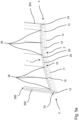
- the first ring segment 210 and the second ring segment 220 form a partial section of a first wind turbine tower section.
- the third ring segment 230 and the fourth ring segment 240 form a partial section of a second wind turbine tower section.
- the first wind turbine tower section is disposed adjacent above the second wind turbine tower section.
- the first ring segment 210 and the second ring segment 220 are arranged together at a vertical joint 300 .
- the third ring segment 230 and the fourth ring segment 240 are arranged together at a vertical joint 310 .
- the vertical joint 300 and the vertical joint 310 are not arranged directly one above the other in the vertical direction but are offset from one another.
- the first ring segment 210 has a first flange segment 214
- the second ring segment 220 has a second flange segment 224
- the third ring segment 230 has a third flange segment 234
- the fourth ring segment 240 has a fourth flange segment 244.
- Flange segments 214, 224, 234, 244 are disposed on ring segments 210, 220, 230, 240 as previously described.
- the vertically adjacent flange segments can be connected to one another through the passage openings arranged in the flange segments.
- figure 6 1 shows how the flange segments 214, 224, 234, 244 are arranged on the ring segments 210, 220, 230, 240.
- the vertical flanges 212, 222, 232, 242 also have passage openings 211, 231, the passage direction of which is aligned essentially in the direction of the ring.
- the vertical flanges can be connected to one another by means of this passage opening and suitable fastening elements, for example screws and nuts.
- Ring segments 200, 210, 220, 230, 240 can be connected to one another in a particularly advantageous manner by means of the flange segments 200, 214, 224, 234, 244 according to the invention. Due to the formation of the flange projection on the flange segments, the flange segments can be arranged in an advantageous manner on the ring segments. In particular, these can be easily arranged on the ring segments by means of a welding process, with no or reduced distortion of the ring segments occurring as a result of the heat input during the welding process.
Landscapes
- Engineering & Computer Science (AREA)
- Chemical & Material Sciences (AREA)
- Architecture (AREA)
- Life Sciences & Earth Sciences (AREA)
- Mechanical Engineering (AREA)
- Combustion & Propulsion (AREA)
- Sustainable Energy (AREA)
- General Engineering & Computer Science (AREA)
- Materials Engineering (AREA)
- Wood Science & Technology (AREA)
- Sustainable Development (AREA)
- Civil Engineering (AREA)
- Structural Engineering (AREA)
- Wind Motors (AREA)
Applications Claiming Priority (2)
| Application Number | Priority Date | Filing Date | Title |
|---|---|---|---|
| DE102017106201.7A DE102017106201A1 (de) | 2017-03-22 | 2017-03-22 | Flanschsegment für ein Windenergieanlagen-Stahlturmringsegment und Verfahren |
| PCT/EP2018/057087 WO2018172386A1 (de) | 2017-03-22 | 2018-03-21 | Flanschsegment für ein windenergieanlagen-stahlturmringsegment und verfahren |
Publications (2)
| Publication Number | Publication Date |
|---|---|
| EP3601791A1 EP3601791A1 (de) | 2020-02-05 |
| EP3601791B1 true EP3601791B1 (de) | 2023-02-15 |
Family
ID=61750138
Family Applications (1)
| Application Number | Title | Priority Date | Filing Date |
|---|---|---|---|
| EP18712595.0A Active EP3601791B1 (de) | 2017-03-22 | 2018-03-21 | Flanschsegment für ein windenergieanlagen-stahlturmringsegment und verfahren |
Country Status (10)
| Country | Link |
|---|---|
| US (1) | US20200080335A1 (ko) |
| EP (1) | EP3601791B1 (ko) |
| JP (1) | JP6918961B2 (ko) |
| KR (1) | KR20190126162A (ko) |
| CN (1) | CN110494649A (ko) |
| BR (1) | BR112019018167A2 (ko) |
| CA (1) | CA3054475A1 (ko) |
| DE (1) | DE102017106201A1 (ko) |
| DK (1) | DK3601791T3 (ko) |
| WO (1) | WO2018172386A1 (ko) |
Families Citing this family (3)
| Publication number | Priority date | Publication date | Assignee | Title |
|---|---|---|---|---|
| DE102019104350A1 (de) * | 2019-02-20 | 2020-08-20 | Wobben Properties Gmbh | Stahlturmringsegment für einen Windenergieanlagen-Turmabschnitt und Verfahren |
| CN109763942A (zh) * | 2019-02-21 | 2019-05-17 | 江苏金海新能源科技有限公司 | 一种预应力混凝土风机塔架及其施工方法 |
| CN116079188B (zh) * | 2023-03-09 | 2024-07-26 | 中铁宝桥集团有限公司 | 倾斜式钢塔节段大断面对接坡口焊接方法 |
Citations (1)
| Publication number | Priority date | Publication date | Assignee | Title |
|---|---|---|---|---|
| US20100024311A1 (en) * | 2008-07-30 | 2010-02-04 | Dustin Jon Wambeke | Wind turbine assembly with tower mount |
Family Cites Families (18)
| Publication number | Priority date | Publication date | Assignee | Title |
|---|---|---|---|---|
| CH675742A5 (ko) * | 1988-09-26 | 1990-10-31 | Fischer Ag Georg | |
| DE10126049A1 (de) | 2001-03-23 | 2002-12-05 | Aloys Wobben | Verbindungsflansch für rohrförmige Bauteile |
| US7096639B2 (en) * | 2001-03-23 | 2006-08-29 | Aloys Wobben | Connecting flange for tubular components and wind turbine tower employing same |
| DE10325032B3 (de) | 2003-06-02 | 2005-01-05 | Aloys Wobben | Verfahren zur Herstellung eines ringförmigen Verbindungsflansches |
| PT1561883E (pt) * | 2004-02-04 | 2007-12-27 | Corus Staal Bv | Torre para uma turbina eólica, parte de parede metálica pré-fabricada para utilização numa torre para uma turbina eólica e método para construção de uma torre para uma turbina eólica. |
| US7387497B2 (en) * | 2005-04-12 | 2008-06-17 | Cone Matthew D | Adapter |
| EP2375057B1 (en) * | 2010-03-31 | 2016-05-04 | Siemens Aktiengesellschaft | Wind turbine installation |
| CN201730768U (zh) * | 2010-06-22 | 2011-02-02 | 沈阳瑞祥风能设备有限公司 | 风力发电机组塔筒连接结构 |
| EP2525021B8 (en) * | 2011-05-16 | 2018-11-28 | GE Renewable Technologies Wind B.V. | Wind turbine tower supporting structure |
| WO2013097866A1 (en) * | 2011-12-28 | 2013-07-04 | Vestas Wind Systems A/S | A ring shaped flange for attachment of a wind turbine tower section to another tower section |
| DE102013016604A1 (de) * | 2013-10-07 | 2015-04-09 | EcoEnterprises GmbH | Stahlrohrturm einer Windenergieanlage, sowie Verfahren zur Herstellung und Montage der Turmbauteile |
| DE102014001996A1 (de) * | 2013-12-12 | 2015-06-18 | Rwe Innogy Gmbh | Anschlussprofil einer Bauwerksstruktur als Offshore- oder Onshore-Struktur und Flanschverbindung an einer solchen Bauwerksstruktur sowie Verfahren zur Errichtung einer Bauwerksstruktur unter Verwendung des Anschlussprofils |
| CN103821677B (zh) * | 2014-03-20 | 2016-07-20 | 哈尔滨工业大学(威海) | 装配式预应力活性粉末混凝土风电塔架 |
| DE102015115645A1 (de) * | 2015-09-16 | 2017-03-16 | SIAG Industrie GmbH | Verfahren zur Herstellung und zum Errichten eines Rohrturmbauwerks |
| WO2016091499A1 (de) * | 2014-12-09 | 2016-06-16 | SIAG Industrie GmbH | Verfahren zur herstellung und zum errichten eines rohrturmbauwerks |
| CN204755192U (zh) * | 2015-05-19 | 2015-11-11 | 南通科赛尔机械有限公司 | 一种改进的塔筒法兰结构 |
| CN204739046U (zh) * | 2015-05-19 | 2015-11-04 | 南通科赛尔机械有限公司 | 一种t型塔筒法兰结构 |
| CN205977555U (zh) * | 2016-08-26 | 2017-02-22 | 三一重型能源装备有限公司 | 预应力塔段及预应力塔筒 |
-
2017
- 2017-03-22 DE DE102017106201.7A patent/DE102017106201A1/de not_active Withdrawn
-
2018
- 2018-03-21 DK DK18712595.0T patent/DK3601791T3/da active
- 2018-03-21 EP EP18712595.0A patent/EP3601791B1/de active Active
- 2018-03-21 CN CN201880020385.4A patent/CN110494649A/zh active Pending
- 2018-03-21 CA CA3054475A patent/CA3054475A1/en not_active Abandoned
- 2018-03-21 US US16/494,241 patent/US20200080335A1/en not_active Abandoned
- 2018-03-21 BR BR112019018167A patent/BR112019018167A2/pt unknown
- 2018-03-21 JP JP2019551943A patent/JP6918961B2/ja active Active
- 2018-03-21 WO PCT/EP2018/057087 patent/WO2018172386A1/de unknown
- 2018-03-21 KR KR1020197030690A patent/KR20190126162A/ko not_active Application Discontinuation
Patent Citations (1)
| Publication number | Priority date | Publication date | Assignee | Title |
|---|---|---|---|---|
| US20100024311A1 (en) * | 2008-07-30 | 2010-02-04 | Dustin Jon Wambeke | Wind turbine assembly with tower mount |
Also Published As
| Publication number | Publication date |
|---|---|
| CA3054475A1 (en) | 2018-09-27 |
| DK3601791T3 (da) | 2023-03-27 |
| WO2018172386A1 (de) | 2018-09-27 |
| DE102017106201A1 (de) | 2018-09-27 |
| BR112019018167A2 (pt) | 2020-04-07 |
| KR20190126162A (ko) | 2019-11-08 |
| CN110494649A (zh) | 2019-11-22 |
| JP6918961B2 (ja) | 2021-08-11 |
| EP3601791A1 (de) | 2020-02-05 |
| US20200080335A1 (en) | 2020-03-12 |
| JP2020512493A (ja) | 2020-04-23 |
Similar Documents
| Publication | Publication Date | Title |
|---|---|---|
| EP2824257B1 (de) | Verfahren zur Herstellung und zum Errichten eines Rohrturmbauwerks | |
| EP2932095B1 (de) | Übergangskörper zur anordnung zwischen unterschiedlich ausgeführten abschnitten eines windkraftanlagenturms und windkraftanlagenturm mit einem solchen übergangskörper | |
| EP2422083A2 (de) | Turm für eine windkraftanlage | |
| EP3601791B1 (de) | Flanschsegment für ein windenergieanlagen-stahlturmringsegment und verfahren | |
| DE102006056274A1 (de) | Turm einer Windkraftanlage | |
| EP3230539B1 (de) | Verfahren zum errichten eines rohrturmbauwerks und rohrturmbauwerk | |
| DE202009015675U1 (de) | Turmsegment, wie auch ein Blechzuschnitt für ein Turmsegment | |
| EP2195530B1 (de) | Mastkonstruktion für fachwerk-türme von windkraftanlagen | |
| EP3436651B1 (de) | Tragstruktur für eine windenergieanlage | |
| DE102015118163A1 (de) | Windenergieturm | |
| EP2692967A2 (de) | Verfahren zum Errichten eines Turmes aus Stahl einer Windenergieanlage und Turm aus Stahl für eine Windenergieanlage | |
| EP3658771B1 (de) | Windenergieanlagen-stahlturmabschnitt für einen windenergieanlagen-turm und verfahren zur herstellung | |
| WO2018019832A1 (de) | Verbindungselement zum verbinden von turmabschnitten, turmabschnitt, turm, windenergieanlage sowie verfahren zum herstellen eines turmabschnitts und zum verbinden von turmabschnitten | |
| DE102017120487A1 (de) | Turm einer Windenergieanlage und Verfahren zum Herstellen eines Sektionssegments für einen solchen Turm | |
| DE102012019595B3 (de) | Öffnung mit Verstärkungselement in einer Tragstruktur einer Windenergieanlage | |
| EP3658770B1 (de) | Windenergieanlagen-stahlturmringsegment und verfahren | |
| EP3467204B1 (de) | Übergangsstück zum verbinden eines oberen turmabschnitts mit einem unteren turmabschnitt mittels verbindungsprofilen | |
| EP3467236B1 (de) | Turm, insbesondere für eine windenergieanlage | |
| EP3956561B1 (de) | Turmsegment und verfahren zum aufbau eines turms | |
| EP3927918B1 (de) | Windenergieanlagen-komponente für einen windenergieanlagen-turm, windenergieanlagen-turm, rotorblatt, windenergieanlage und verfahren zur herstellung einer windenergieanlagen-komponente | |
| DE102009007999A1 (de) | Leitringelement für Turbinen und Verfahren zu dessen Herstellung |
Legal Events
| Date | Code | Title | Description |
|---|---|---|---|
| STAA | Information on the status of an ep patent application or granted ep patent |
Free format text: STATUS: UNKNOWN |
|
| STAA | Information on the status of an ep patent application or granted ep patent |
Free format text: STATUS: THE INTERNATIONAL PUBLICATION HAS BEEN MADE |
|
| PUAI | Public reference made under article 153(3) epc to a published international application that has entered the european phase |
Free format text: ORIGINAL CODE: 0009012 |
|
| STAA | Information on the status of an ep patent application or granted ep patent |
Free format text: STATUS: REQUEST FOR EXAMINATION WAS MADE |
|
| 17P | Request for examination filed |
Effective date: 20191022 |
|
| AK | Designated contracting states |
Kind code of ref document: A1 Designated state(s): AL AT BE BG CH CY CZ DE DK EE ES FI FR GB GR HR HU IE IS IT LI LT LU LV MC MK MT NL NO PL PT RO RS SE SI SK SM TR |
|
| AX | Request for extension of the european patent |
Extension state: BA ME |
|
| DAV | Request for validation of the european patent (deleted) | ||
| DAX | Request for extension of the european patent (deleted) | ||
| STAA | Information on the status of an ep patent application or granted ep patent |
Free format text: STATUS: EXAMINATION IS IN PROGRESS |
|
| 17Q | First examination report despatched |
Effective date: 20200921 |
|
| STAA | Information on the status of an ep patent application or granted ep patent |
Free format text: STATUS: EXAMINATION IS IN PROGRESS |
|
| GRAP | Despatch of communication of intention to grant a patent |
Free format text: ORIGINAL CODE: EPIDOSNIGR1 |
|
| STAA | Information on the status of an ep patent application or granted ep patent |
Free format text: STATUS: GRANT OF PATENT IS INTENDED |
|
| INTG | Intention to grant announced |
Effective date: 20220901 |
|
| GRAS | Grant fee paid |
Free format text: ORIGINAL CODE: EPIDOSNIGR3 |
|
| GRAA | (expected) grant |
Free format text: ORIGINAL CODE: 0009210 |
|
| STAA | Information on the status of an ep patent application or granted ep patent |
Free format text: STATUS: THE PATENT HAS BEEN GRANTED |
|
| AK | Designated contracting states |
Kind code of ref document: B1 Designated state(s): AL AT BE BG CH CY CZ DE DK EE ES FI FR GB GR HR HU IE IS IT LI LT LU LV MC MK MT NL NO PL PT RO RS SE SI SK SM TR |
|
| REG | Reference to a national code |
Ref country code: CH Ref legal event code: EP Ref country code: GB Ref legal event code: FG4D Free format text: NOT ENGLISH |
|
| REG | Reference to a national code |
Ref country code: DE Ref legal event code: R096 Ref document number: 502018011587 Country of ref document: DE |
|
| REG | Reference to a national code |
Ref country code: NL Ref legal event code: FP |
|
| REG | Reference to a national code |
Ref country code: AT Ref legal event code: REF Ref document number: 1548355 Country of ref document: AT Kind code of ref document: T Effective date: 20230315 Ref country code: IE Ref legal event code: FG4D Free format text: LANGUAGE OF EP DOCUMENT: GERMAN |
|
| REG | Reference to a national code |
Ref country code: DK Ref legal event code: T3 Effective date: 20230322 |
|
| REG | Reference to a national code |
Ref country code: LT Ref legal event code: MG9D |
|
| PG25 | Lapsed in a contracting state [announced via postgrant information from national office to epo] |
Ref country code: RS Free format text: LAPSE BECAUSE OF FAILURE TO SUBMIT A TRANSLATION OF THE DESCRIPTION OR TO PAY THE FEE WITHIN THE PRESCRIBED TIME-LIMIT Effective date: 20230215 Ref country code: PT Free format text: LAPSE BECAUSE OF FAILURE TO SUBMIT A TRANSLATION OF THE DESCRIPTION OR TO PAY THE FEE WITHIN THE PRESCRIBED TIME-LIMIT Effective date: 20230615 Ref country code: NO Free format text: LAPSE BECAUSE OF FAILURE TO SUBMIT A TRANSLATION OF THE DESCRIPTION OR TO PAY THE FEE WITHIN THE PRESCRIBED TIME-LIMIT Effective date: 20230515 Ref country code: LV Free format text: LAPSE BECAUSE OF FAILURE TO SUBMIT A TRANSLATION OF THE DESCRIPTION OR TO PAY THE FEE WITHIN THE PRESCRIBED TIME-LIMIT Effective date: 20230215 Ref country code: LT Free format text: LAPSE BECAUSE OF FAILURE TO SUBMIT A TRANSLATION OF THE DESCRIPTION OR TO PAY THE FEE WITHIN THE PRESCRIBED TIME-LIMIT Effective date: 20230215 Ref country code: HR Free format text: LAPSE BECAUSE OF FAILURE TO SUBMIT A TRANSLATION OF THE DESCRIPTION OR TO PAY THE FEE WITHIN THE PRESCRIBED TIME-LIMIT Effective date: 20230215 Ref country code: ES Free format text: LAPSE BECAUSE OF FAILURE TO SUBMIT A TRANSLATION OF THE DESCRIPTION OR TO PAY THE FEE WITHIN THE PRESCRIBED TIME-LIMIT Effective date: 20230215 |
|
| PG25 | Lapsed in a contracting state [announced via postgrant information from national office to epo] |
Ref country code: SE Free format text: LAPSE BECAUSE OF FAILURE TO SUBMIT A TRANSLATION OF THE DESCRIPTION OR TO PAY THE FEE WITHIN THE PRESCRIBED TIME-LIMIT Effective date: 20230215 Ref country code: PL Free format text: LAPSE BECAUSE OF FAILURE TO SUBMIT A TRANSLATION OF THE DESCRIPTION OR TO PAY THE FEE WITHIN THE PRESCRIBED TIME-LIMIT Effective date: 20230215 Ref country code: IS Free format text: LAPSE BECAUSE OF FAILURE TO SUBMIT A TRANSLATION OF THE DESCRIPTION OR TO PAY THE FEE WITHIN THE PRESCRIBED TIME-LIMIT Effective date: 20230615 Ref country code: GR Free format text: LAPSE BECAUSE OF FAILURE TO SUBMIT A TRANSLATION OF THE DESCRIPTION OR TO PAY THE FEE WITHIN THE PRESCRIBED TIME-LIMIT Effective date: 20230516 Ref country code: FI Free format text: LAPSE BECAUSE OF FAILURE TO SUBMIT A TRANSLATION OF THE DESCRIPTION OR TO PAY THE FEE WITHIN THE PRESCRIBED TIME-LIMIT Effective date: 20230215 |
|
| PG25 | Lapsed in a contracting state [announced via postgrant information from national office to epo] |
Ref country code: SM Free format text: LAPSE BECAUSE OF FAILURE TO SUBMIT A TRANSLATION OF THE DESCRIPTION OR TO PAY THE FEE WITHIN THE PRESCRIBED TIME-LIMIT Effective date: 20230215 Ref country code: RO Free format text: LAPSE BECAUSE OF FAILURE TO SUBMIT A TRANSLATION OF THE DESCRIPTION OR TO PAY THE FEE WITHIN THE PRESCRIBED TIME-LIMIT Effective date: 20230215 Ref country code: EE Free format text: LAPSE BECAUSE OF FAILURE TO SUBMIT A TRANSLATION OF THE DESCRIPTION OR TO PAY THE FEE WITHIN THE PRESCRIBED TIME-LIMIT Effective date: 20230215 Ref country code: CZ Free format text: LAPSE BECAUSE OF FAILURE TO SUBMIT A TRANSLATION OF THE DESCRIPTION OR TO PAY THE FEE WITHIN THE PRESCRIBED TIME-LIMIT Effective date: 20230215 |
|
| REG | Reference to a national code |
Ref country code: CH Ref legal event code: PL |
|
| REG | Reference to a national code |
Ref country code: DE Ref legal event code: R097 Ref document number: 502018011587 Country of ref document: DE |
|
| PG25 | Lapsed in a contracting state [announced via postgrant information from national office to epo] |
Ref country code: SK Free format text: LAPSE BECAUSE OF FAILURE TO SUBMIT A TRANSLATION OF THE DESCRIPTION OR TO PAY THE FEE WITHIN THE PRESCRIBED TIME-LIMIT Effective date: 20230215 |
|
| REG | Reference to a national code |
Ref country code: BE Ref legal event code: MM Effective date: 20230331 |
|
| PLBE | No opposition filed within time limit |
Free format text: ORIGINAL CODE: 0009261 |
|
| STAA | Information on the status of an ep patent application or granted ep patent |
Free format text: STATUS: NO OPPOSITION FILED WITHIN TIME LIMIT |
|
| PG25 | Lapsed in a contracting state [announced via postgrant information from national office to epo] |
Ref country code: LU Free format text: LAPSE BECAUSE OF NON-PAYMENT OF DUE FEES Effective date: 20230321 |
|
| PG25 | Lapsed in a contracting state [announced via postgrant information from national office to epo] |
Ref country code: MC Free format text: LAPSE BECAUSE OF FAILURE TO SUBMIT A TRANSLATION OF THE DESCRIPTION OR TO PAY THE FEE WITHIN THE PRESCRIBED TIME-LIMIT Effective date: 20230215 |
|
| REG | Reference to a national code |
Ref country code: IE Ref legal event code: MM4A |
|
| 26N | No opposition filed |
Effective date: 20231116 |
|
| PG25 | Lapsed in a contracting state [announced via postgrant information from national office to epo] |
Ref country code: SI Free format text: LAPSE BECAUSE OF FAILURE TO SUBMIT A TRANSLATION OF THE DESCRIPTION OR TO PAY THE FEE WITHIN THE PRESCRIBED TIME-LIMIT Effective date: 20230215 Ref country code: MC Free format text: LAPSE BECAUSE OF FAILURE TO SUBMIT A TRANSLATION OF THE DESCRIPTION OR TO PAY THE FEE WITHIN THE PRESCRIBED TIME-LIMIT Effective date: 20230215 Ref country code: LI Free format text: LAPSE BECAUSE OF NON-PAYMENT OF DUE FEES Effective date: 20230331 Ref country code: IE Free format text: LAPSE BECAUSE OF NON-PAYMENT OF DUE FEES Effective date: 20230321 Ref country code: CH Free format text: LAPSE BECAUSE OF NON-PAYMENT OF DUE FEES Effective date: 20230331 |
|
| PG25 | Lapsed in a contracting state [announced via postgrant information from national office to epo] |
Ref country code: BE Free format text: LAPSE BECAUSE OF NON-PAYMENT OF DUE FEES Effective date: 20230331 |
|
| PGFP | Annual fee paid to national office [announced via postgrant information from national office to epo] |
Ref country code: NL Payment date: 20240320 Year of fee payment: 7 |
|
| PGFP | Annual fee paid to national office [announced via postgrant information from national office to epo] |
Ref country code: GB Payment date: 20240322 Year of fee payment: 7 |
|
| REG | Reference to a national code |
Ref country code: AT Ref legal event code: MM01 Ref document number: 1548355 Country of ref document: AT Kind code of ref document: T Effective date: 20230321 |
|
| PG25 | Lapsed in a contracting state [announced via postgrant information from national office to epo] |
Ref country code: IT Free format text: LAPSE BECAUSE OF FAILURE TO SUBMIT A TRANSLATION OF THE DESCRIPTION OR TO PAY THE FEE WITHIN THE PRESCRIBED TIME-LIMIT Effective date: 20230215 |
|
| PGFP | Annual fee paid to national office [announced via postgrant information from national office to epo] |
Ref country code: FR Payment date: 20240320 Year of fee payment: 7 Ref country code: DK Payment date: 20240321 Year of fee payment: 7 |
|
| PGFP | Annual fee paid to national office [announced via postgrant information from national office to epo] |
Ref country code: DE Payment date: 20240412 Year of fee payment: 7 |
|
| PG25 | Lapsed in a contracting state [announced via postgrant information from national office to epo] |
Ref country code: AT Free format text: LAPSE BECAUSE OF NON-PAYMENT OF DUE FEES Effective date: 20230321 |
|
| PG25 | Lapsed in a contracting state [announced via postgrant information from national office to epo] |
Ref country code: AT Free format text: LAPSE BECAUSE OF NON-PAYMENT OF DUE FEES Effective date: 20230321 |