EP3600949B1 - Zweispannungsbatterie - Google Patents
Zweispannungsbatterie Download PDFInfo
- Publication number
- EP3600949B1 EP3600949B1 EP18712191.8A EP18712191A EP3600949B1 EP 3600949 B1 EP3600949 B1 EP 3600949B1 EP 18712191 A EP18712191 A EP 18712191A EP 3600949 B1 EP3600949 B1 EP 3600949B1
- Authority
- EP
- European Patent Office
- Prior art keywords
- electrical system
- vehicle electrical
- battery
- connection
- voltage
- Prior art date
- Legal status (The legal status is an assumption and is not a legal conclusion. Google has not performed a legal analysis and makes no representation as to the accuracy of the status listed.)
- Active
Links
Images




Classifications
-
- H—ELECTRICITY
- H02—GENERATION; CONVERSION OR DISTRIBUTION OF ELECTRIC POWER
- H02J—ELECTRIC POWER NETWORKS; CIRCUIT ARRANGEMENTS OR SYSTEMS FOR SUPPLYING OR DISTRIBUTING ELECTRIC POWER; SYSTEMS FOR STORING ELECTRIC ENERGY
- H02J7/00—Circuit arrangements for charging or discharging batteries or for supplying loads from batteries
- H02J7/50—Circuit arrangements for charging or discharging batteries or for supplying loads from batteries acting upon multiple batteries simultaneously or sequentially
- H02J7/575—Parallel/serial switching of connection of batteries to charge or load circuit
-
- B—PERFORMING OPERATIONS; TRANSPORTING
- B60—VEHICLES IN GENERAL
- B60L—PROPULSION OF ELECTRICALLY-PROPELLED VEHICLES; SUPPLYING ELECTRIC POWER FOR AUXILIARY EQUIPMENT OF ELECTRICALLY-PROPELLED VEHICLES; ELECTRODYNAMIC BRAKE SYSTEMS FOR VEHICLES IN GENERAL; MAGNETIC SUSPENSION OR LEVITATION FOR VEHICLES; MONITORING OPERATING VARIABLES OF ELECTRICALLY-PROPELLED VEHICLES; ELECTRIC SAFETY DEVICES FOR ELECTRICALLY-PROPELLED VEHICLES
- B60L58/00—Methods or circuit arrangements for monitoring or controlling batteries or fuel cells, specially adapted for electric vehicles
- B60L58/10—Methods or circuit arrangements for monitoring or controlling batteries or fuel cells, specially adapted for electric vehicles for monitoring or controlling batteries
- B60L58/18—Methods or circuit arrangements for monitoring or controlling batteries or fuel cells, specially adapted for electric vehicles for monitoring or controlling batteries of two or more battery modules
- B60L58/19—Switching between serial connection and parallel connection of battery modules
-
- B—PERFORMING OPERATIONS; TRANSPORTING
- B60—VEHICLES IN GENERAL
- B60R—VEHICLES, VEHICLE FITTINGS, OR VEHICLE PARTS, NOT OTHERWISE PROVIDED FOR
- B60R16/00—Electric or fluid circuits specially adapted for vehicles and not otherwise provided for; Arrangement of elements of electric or fluid circuits specially adapted for vehicles and not otherwise provided for
- B60R16/02—Electric or fluid circuits specially adapted for vehicles and not otherwise provided for; Arrangement of elements of electric or fluid circuits specially adapted for vehicles and not otherwise provided for electric constitutive elements
- B60R16/03—Electric or fluid circuits specially adapted for vehicles and not otherwise provided for; Arrangement of elements of electric or fluid circuits specially adapted for vehicles and not otherwise provided for electric constitutive elements for supply of electrical power to vehicle subsystems or for
- B60R16/033—Electric or fluid circuits specially adapted for vehicles and not otherwise provided for; Arrangement of elements of electric or fluid circuits specially adapted for vehicles and not otherwise provided for electric constitutive elements for supply of electrical power to vehicle subsystems or for characterised by the use of electrical cells or batteries
-
- H—ELECTRICITY
- H02—GENERATION; CONVERSION OR DISTRIBUTION OF ELECTRIC POWER
- H02J—ELECTRIC POWER NETWORKS; CIRCUIT ARRANGEMENTS OR SYSTEMS FOR SUPPLYING OR DISTRIBUTING ELECTRIC POWER; SYSTEMS FOR STORING ELECTRIC ENERGY
- H02J1/00—Circuit arrangements for DC mains or DC distribution networks
- H02J1/08—Three-wire DC power distribution systems; Systems having more than three wires
- H02J1/082—DC supplies with two or more different DC voltage levels
-
- B—PERFORMING OPERATIONS; TRANSPORTING
- B60—VEHICLES IN GENERAL
- B60Y—INDEXING SCHEME RELATING TO ASPECTS CROSS-CUTTING VEHICLE TECHNOLOGY
- B60Y2300/00—Purposes or special features of road vehicle drive control systems
- B60Y2300/91—Battery charging
-
- H—ELECTRICITY
- H02—GENERATION; CONVERSION OR DISTRIBUTION OF ELECTRIC POWER
- H02M—APPARATUS FOR CONVERSION BETWEEN AC AND AC, BETWEEN AC AND DC, OR BETWEEN DC AND DC, AND FOR USE WITH MAINS OR SIMILAR POWER SUPPLY SYSTEMS; CONVERSION OF DC OR AC INPUT POWER INTO SURGE OUTPUT POWER; CONTROL OR REGULATION THEREOF
- H02M3/00—Conversion of DC power input into DC power output
- H02M3/02—Conversion of DC power input into DC power output without intermediate conversion into AC
- H02M3/04—Conversion of DC power input into DC power output without intermediate conversion into AC by static converters
- H02M3/10—Conversion of DC power input into DC power output without intermediate conversion into AC by static converters using discharge tubes with control electrode or semiconductor devices with control electrode
- H02M3/145—Conversion of DC power input into DC power output without intermediate conversion into AC by static converters using discharge tubes with control electrode or semiconductor devices with control electrode using devices of a triode or transistor type requiring continuous application of a control signal
- H02M3/155—Conversion of DC power input into DC power output without intermediate conversion into AC by static converters using discharge tubes with control electrode or semiconductor devices with control electrode using devices of a triode or transistor type requiring continuous application of a control signal using semiconductor devices only
- H02M3/156—Conversion of DC power input into DC power output without intermediate conversion into AC by static converters using discharge tubes with control electrode or semiconductor devices with control electrode using devices of a triode or transistor type requiring continuous application of a control signal using semiconductor devices only with automatic control of output voltage or current, e.g. switching regulators
- H02M3/157—Conversion of DC power input into DC power output without intermediate conversion into AC by static converters using discharge tubes with control electrode or semiconductor devices with control electrode using devices of a triode or transistor type requiring continuous application of a control signal using semiconductor devices only with automatic control of output voltage or current, e.g. switching regulators with digital control
-
- Y—GENERAL TAGGING OF NEW TECHNOLOGICAL DEVELOPMENTS; GENERAL TAGGING OF CROSS-SECTIONAL TECHNOLOGIES SPANNING OVER SEVERAL SECTIONS OF THE IPC; TECHNICAL SUBJECTS COVERED BY FORMER USPC CROSS-REFERENCE ART COLLECTIONS [XRACs] AND DIGESTS
- Y02—TECHNOLOGIES OR APPLICATIONS FOR MITIGATION OR ADAPTATION AGAINST CLIMATE CHANGE
- Y02T—CLIMATE CHANGE MITIGATION TECHNOLOGIES RELATED TO TRANSPORTATION
- Y02T10/00—Road transport of goods or passengers
- Y02T10/60—Other road transportation technologies with climate change mitigation effect
- Y02T10/70—Energy storage systems for electromobility, e.g. batteries
Definitions
- a dual-voltage battery of the type mentioned at the beginning is from the document DE 10 2013 113 182 A1 known.
- the known two-voltage battery is constructed in such a way that in a two-voltage vehicle electrical system, a first group of electrical consumers can be operated at the first vehicle electrical system voltage by means of the battery and that a second group of electrical consumers can be operated at the second, higher vehicle electrical system voltage.
- the dual-voltage battery is used to supply energy for a 12 V on-board electrical system and for a 48 V on-board electrical system.
- the two voltages can be made available by the dual-voltage battery, in particular simultaneously, via the vehicle electrical system connections.
- the higher second vehicle electrical system voltage can be provided by each battery submodule independently of any other battery submodule.
- the object of the present invention is to improve the service life of the battery by equalizing the current throughput through the different battery cell blocks of the dual-voltage battery.
- the invention has the features of patent claim 1. It is provided in this respect that the voltage across all battery cell blocks of the battery submodule in the second connection arrangement corresponds to a voltage between the second vehicle electrical system connection and the first vehicle electrical system connection.
- the particular advantage of the invention is that no battery cell block of the dual-voltage battery according to the invention is permanently assigned to an on-board electrical system voltage and in particular not to the first on-board electrical system voltage. There is therefore no distinction between switching and non-switching battery cell blocks.
- This measure according to the invention, achieves a balanced current throughput through all battery cell blocks and all battery cells of the different battery cell blocks is guaranteed, with the result that the service life of the dual-voltage battery is optimized. At the same time, there is no need to transfer energy between highly charged and weakly charged areas.
- the structure of the individual battery cells is simplified and a large number of battery cells and/or battery submodules can be implemented with identical construction and cost-effectively. Since at least one battery submodule is available for each vehicle electrical system voltage at any time, the backup energy storage for the first electrical consumer operated at the first vehicle electrical system voltage and the second electrical consumer operated at the second vehicle electrical system voltage can be dispensed with.
- a multi-voltage battery which has a total of four battery cell blocks 11, 12, 61, 62.
- Two battery cell blocks each form a pair 11, 12 and 61, 62.
- the blocks of these pairs are connected by switches 13, 14, 15, 16 and 63, 64, 65, 66, respectively.
- the switches can be switched so that the blocks of the pairs are connected in series or in parallel.
- a voltage can be tapped at different points A, B, C or A', B', C'.
- the pairs can be connected in parallel or in series using additional switches 67, 68, 69, 70.
- the battery cells or battery cell blocks are charged, for example, by a generator assigned to the dual-voltage battery, which is operated conventionally, or by recovering braking energy.
- a negative pole of a first battery cell block of the battery submodule is connected to the first vehicle electrical system connection and a positive pole of a last battery cell block of the battery submodule is connected to the second vehicle electrical system connection.
- further battery cell blocks of the battery submodule are connected in series between the first battery cell block and the last battery cell block.
- the negative pole of the first battery cell block is then at the voltage level of the first vehicle electrical system connection and the second vehicle electrical system connection has a voltage level that is higher by the sum of the individual voltages of the battery cell blocks.
- three or more battery submodules are provided, which are connected in parallel to one another with respect to the first vehicle electrical system connection and with respect to the second vehicle electrical system connection.
- switching the configuration of the battery submodules is simplified in that even during the switchover itself, at least one battery submodule can always provide the first vehicle electrical system voltage and a second battery submodule can always provide the second vehicle electrical system voltage. This avoids an at least temporary interruption in the provision of the low first vehicle electrical system voltage and the higher second vehicle electrical system voltage.
- all battery submodules are constructed identically. They therefore have the same number of switching elements and the same number of battery cell blocks or battery cells.
- the configuration of the switching elements and battery cell blocks or battery cells of all battery submodules is identical.
- the structure of the dual-voltage battery is advantageously simplified and the battery submodules can be manufactured cost-effectively and in large quantities with identical construction.
- a DC/DC converter is provided between the first connection point and the second connection point of the dual-voltage battery to support the on-board networks.
- the dual-voltage battery according to the invention provides an additional vehicle electrical system connection.
- the additional vehicle electrical system connection the at least two battery cell blocks of the at least one battery submodule can be connected in a parallel connection and/or in a series connection via the switching elements and additional switching elements. All battery submodules of the dual-voltage battery are arranged in parallel with one another in relation to the additional vehicle electrical system connection.
- a decoupling can be achieved between the first vehicle electrical system operated at the low vehicle electrical system voltage and the second vehicle electrical system operated at the high vehicle electrical system voltage.
- the consumers of the first on-board electrical system can be supplied independently and reliably when the on-board electrical systems are separated.
- the first vehicle electrical system voltage is provided at the additional vehicle electrical system connection.
- the additional on-board power supply connection can preferably be provided within the battery alone. In this respect, there is no provision for a tap for the additional on-board electrical system connection to be routed to the outside via the housing of the dual-voltage battery.
- the additional vehicle electrical system connection can advantageously provide a basic voltage level for the second high vehicle electrical system voltage. In this respect, it takes over the electrical function of the first on-board electrical system connection - albeit only within the battery. Nevertheless, the first vehicle electrical system connection is implemented and decoupled separately from the additional vehicle electrical system connection and/or from the second vehicle electrical system connection.
- a detector unit By means of the detector unit, a charging current and/or a discharging current and/or an embossed voltage and/or a voltage change at the second vehicle electrical system connection are detected.
- a central control unit is preferably provided, which is designed to actuate the switching elements and/or the additional switching elements and is in an operative connection with them. The switching elements are actuated depending on an input control signal supplied to the central control unit. An output signal from the detector unit, for example, serves as the input control signal for the central control unit.
- the detector unit and its interaction with the central control unit load-dependent actuation of the switching elements and thus a reliable supply of consumers in the first vehicle electrical system and in the second vehicle electrical system can be achieved.
- the on-board electrical systems can be separated by circuitry or a particularly highly loaded on-board electrical system can be supported by switching battery cell blocks.
- a dual voltage battery 1 comprises as essential functional components a first battery sub-module 2 with a first on-board network connection 3, with a second on-board network connection 4 and with a ground connection point 5, a DC/DC converter 6 provided between the ground connection points 3, 4, a generator 7 assigned to the second on-board network connection 4 as an example, as well as a first backup energy storage device 8 and a second backup energy storage device 9.
- the first auxiliary energy storage device 8 is assigned to a consumer 10 shown as an example, which is connected to the first on-board network connection 3 and is operated at a low first on-board network voltage.
- the second auxiliary energy storage device 9 is assigned to a second consumer 11, which is connected to the second on-board network connection 4 and is operated at a second, high on-board network voltage.
- the battery submodule 2 of the dual-voltage battery 1 comprises two battery cell blocks 12, 13.
- the two battery cell blocks 12, 13, which are constructed from a plurality of battery cells, not shown individually, and preferably of identical construction, are provided with a plurality of switching elements 14, 15, 16, 17, 18, 19, 20 assigned.
- the switching elements 14, 15, 16, 17, 18, 19, 20 are designed and arranged for selectively connecting the battery cell blocks 12, 13 in parallel and in series.
- the battery cell blocks 12, 13 of the battery submodule 2 are connected in parallel such that the first vehicle electrical system voltage is provided at the first vehicle electrical system connection 3.
- the switching elements 15, 16, 18, 19 are therefore closed and the switching elements 14, 17, 20 are open.
- the battery cell blocks 12, 13 of the battery submodule 2 are connected in series.
- the second vehicle electrical system voltage is provided at the second vehicle electrical system connection 4.
- the switching elements 14, 17, 20 are closed and the switching elements 15, 16, 18, 19 are open for serial connection of the battery cell blocks 12, 13.
- the dual-voltage battery 1 now comprises two identical battery submodules 21, 22.
- the internal structure of the battery submodules 21, 22 corresponds to the structure of the battery submodule 2 according to Fig.1 . A detailed repetition of the structure is therefore omitted.
- the first vehicle electrical system voltage and the second vehicle electrical system voltage can be provided to the dual-voltage battery 1 at the same time.
- the connection arrangements of the battery submodules 21, 22 can be switched.
- the first backup energy storage 8 and/or the second backup energy storage 9 temporarily takes over the supply of the consumers 10, 11 in the first vehicle electrical system or in the second vehicle electrical system.
- the first battery submodule 21 can be moved from the second connection arrangement to the first connection arrangement.
- the first vehicle electrical system voltage is then provided at the first vehicle electrical system connection 3 by the first battery submodule 21 and the second battery submodule 22, at least for a short time.
- the electrical consumer 11, which is operated at the second vehicle electrical system voltage, is then temporarily operated via the second backup energy store 9.
- the second battery submodule 22 is then subsequently moved from the first connection arrangement to the second connection arrangement, so that the second vehicle electrical system voltage for the second consumer 11 is now provided by the second battery submodule 22.
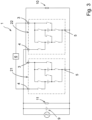
- FIG. 3 A correspondingly adapted and simplified configuration of the dual-voltage battery 1 is exemplified in Fig. 3 shown. It is in Fig. 3 the dual-voltage battery 1 is provided with two identical battery submodules 21, 22, which are compared to the configuration according to Fig. 2 only the backup energy storage 8 for the first vehicle electrical system is dispensed with and otherwise according to the first configuration of the two-voltage battery 1 with two battery submodules 21, 22 Fig. 2 corresponds.
- the dual-voltage battery 1 according to the invention with three identical battery submodules 23, 24, 25 Fig. 4 is designed redundantly in such a way that permanently and in particular also when changing or switching the connection arrangement for the battery submodules 23, 24, 25, at least one battery submodule 23, 24, 25 each has the first vehicle electrical system voltage at the first vehicle electrical system connection 3 or at least one battery submodule 23, 24, 25 the second vehicle electrical system voltage is provided at the second vehicle electrical system connection 4.
- the backup energy storage devices 8, 9 for the first electrical consumer 10 operated at the first vehicle electrical system voltage and the second electrical consumer 11 operated at the second vehicle electrical system voltage can be dispensed with.
- a correspondingly adapted configuration is shown in Fig.5 shown.
- an additional vehicle electrical system connection 26 is formed inside the battery and that the three battery submodules 27, 28, 29 of the dual-voltage battery 1 according to the invention provide the low first vehicle electrical system voltage at the additional vehicle electrical system connection 26 as well as at the first vehicle electrical system connection 3.
- the high second vehicle electrical system voltage is provided unchanged at the second vehicle electrical system connection 4.
- the battery submodules 27, 28, 29 can provide the low first vehicle electrical system voltage at the first vehicle electrical system connection 3 by the switching elements 15, 16, 18, 19 being closed and all further switching elements 17, 20 as well as additionally provided switching elements 30, 31 being opened.
- the low first vehicle electrical system voltage can also be provided simultaneously at the first vehicle electrical system connection 3 and at the additional vehicle electrical system connection 26 by additionally closing the additional switching element 30.
- the low first vehicle electrical system voltage can be provided solely at the additional vehicle electrical system connection 26 by closing the additional switching element 30 and opening the switching element 15.
- the high second vehicle electrical system voltage is preferably provided by connecting the battery cell blocks 12, 13 in series starting from the additional vehicle electrical system connection 26. For this purpose, the additional switching element 31 and the switching elements 17 and 20 are closed, while all other switching elements and the additional switching element 30 are open.
- a first battery submodule 27 at the first vehicle electrical system connection 3 can provide the low first voltage to supply the electrical consumer 10 in the first vehicle electrical system.
- a second battery submodule 28 can provide the low first vehicle electrical system voltage at the additional vehicle electrical system connection 26.
- the third battery submodule 29 can then provide the high second vehicle electrical system voltage to supply the electrical consumer 11 in the second vehicle electrical system.
- the first vehicle electrical system and the second vehicle electrical system are separated from one another so that, for example, high charging or discharging currents in the second vehicle electrical system or voltage changes in the second vehicle electrical system do not have any repercussions on the first vehicle electrical system.
- the electrical consumer 10 in the first vehicle electrical system is therefore reliably supplied with electrical energy.
- Fig.8 shows a comparison of a dual-voltage battery according to the invention with a dual-voltage battery known from the prior art.
- the dual-voltage battery according to the invention has four battery submodules, each with two battery cell blocks 12.1, 12.2, 12.3, 12.4, 13.1, 13.2, 13.3, 13.4, which in the form presented have the first vehicle electrical system voltage at the first vehicle electrical system connection 3 and/or the second vehicle electrical system voltage on the second vehicle electrical system connection 4.
- An additional vehicle electrical system connection 26 can optionally be provided.
- the two-voltage battery referred to in the prior art provides two battery cell blocks 12.4, 13.4, which permanently serve to supply the first vehicle electrical system at the first vehicle electrical system voltage.
- two battery submodules, each with three battery cells are provided, which can be connected in parallel to provide the first vehicle electrical system voltage and/or provide the second vehicle electrical system voltage in a series connection.
- individual battery cell blocks are very heavily loaded, whereas other battery cell blocks have a very low battery current.
- the service life of the dual-voltage battery known from the prior art is therefore shorter than the service life of the dual-voltage battery according to the invention.
Landscapes
- Engineering & Computer Science (AREA)
- Power Engineering (AREA)
- Mechanical Engineering (AREA)
- Life Sciences & Earth Sciences (AREA)
- Sustainable Development (AREA)
- Sustainable Energy (AREA)
- Transportation (AREA)
- Charge And Discharge Circuits For Batteries Or The Like (AREA)
- Electric Propulsion And Braking For Vehicles (AREA)
- Secondary Cells (AREA)
Description
- Die Erfindung betrifft eine Zweispannungsbatterie für ein Fahrzeug
- mit mindestens einem Masseanschlusspunkt,
- mit einem ersten Bordnetzanschluss, an dem eine niedrige erste Bordnetzspannung gegenüber dem Masseanschlusspunkt bereitgestellt ist, und
- mit einem zweiten Bordnetzanschluss, an dem eine hohe zweite Bordnetzspannung gegenüber dem Masseanschlusspunkt bereitgestellt ist,
- wobei drei oder mehr Batteriesubmodule vorgesehen sind, welche sowohl bezogen auf den ersten Bordnetzanschluss und den Massenanschlusspunkt als auch bezogen auf den zweiten Bordnetzanschluss und den Massenanschlusspunkt zueinander parallel verschaltet sind,
- wobei in jedem Batteriesubmodul mindestens zwei Batteriezellblöcke sowie eine Mehrzahl von Schaltelementen zum wahlweisen parallelen und/oder seriellen Verbinden der Batteriezellblöcke vorgesehen sind,
- wobei in einer ersten Verbindungsanordnung der Batteriezellblöcke dieselben zwischen dem Masseanschluss und dem ersten Bordnetzanschluss zueinander parallel verschaltet sind derart, dass an dem ersten Bordnetzanschluss die erste Bordnetzspannung gegenüber dem Masseanschlusspunkt bereitgestellt ist, und
- wobei die Schaltelemente in einer zweiten Verbindungsanordnung der Batteriezellblöcke Batteriezellblöcke der Batteriesubmodule zwischen dem ersten Bordnetzanschluss und dem zweiten Bordnetzanschluss seriell miteinander verbinden derart, dass an dem zweiten Bordnetzanschluss zum Bereitstellen der zweiten Bordnetzspannung eine Spannung gegenüber dem ersten Bordnetzanschluss bereitgestellt ist, und
- wobei die Zweispannungsbatterie so eingerichtet ist, dass bei einer Umschaltung der Verbindungsanordnung der Batteriezellblöcke der Batteriesubmodule stets wenigstens ein Batteriesubmodul die erste Bordnetzspannung und ein anderes Batteriesubmodul die zweite Bordnetzspannung bereitstellt, so dass eine temporäre Unterbrechung in der Bereitstellung der niedrigen ersten Bordnetzspannung und der höheren zweiten Bordnetzspannung vermieden ist.
- Eine Zweispannungsbatterie der eingangs genannten Art ist aus dem Dokument
DE 10 2013 113 182 A1 bekannt. Die bekannte Zweispannungsbatterie ist so aufgebaut, dass in einem Zweispannungsbordnetz mittels der Batterie eine erste Gruppe von elektrischen Verbrauchern bei der ersten Bordnetzspannung betrieben werden kann und dass eine zweite Gruppe von elektrischen Verbrauchern bei der zweiten, höheren Bordnetzspannung betrieben werden kann. Beispielsweise dient die Zweispannungsbatterie der Energieversorgung für ein 12 V-Bordnetz und für ein 48 V-Bordnetz. Die zwei Spannungen können von der Zweispannungsbatterie insbesondere gleichzeitig über die Bordnetzanschlüsse zur Verfügung gestellt werden. Nach der Lehre des DokumentesDE 10 2013 113 182 A1 kann durch jedes Batteriesubmodul unabhängig von jedem anderen Batteriesubmodul die höhere zweite Bordnetzspannung bereitgestellt werden. - Aufgabe der vorliegenden Erfindung ist es, eine Lebensdauer der Batterie zu verbessern, indem der Stromdurchsatz durch die verschiedenen Batteriezellblöcke der Zweispannungsbatterie angeglichen wird.
- Zur Lösung der Aufgabe weist die Erfindung die Merkmale des Patentanspruchs 1 auf. Es ist insofern vorgesehen, dass die Spannung über alle Batteriezellblöcke des Batteriesubmoduls in der zweiten Verbindungsanordnung einer Spannung zwischen dem zweiten Bordnetzanschluss und dem ersten Bordnetzanschluss entspricht.
- Der besondere Vorteil der Erfindung besteht darin, dass kein Batteriezellblock der erfindungsgemäßen Zweispannungsbatterie fest einer Bordnetzspannung und insbesondere nicht der ersten Bordnetzspannung zugeordnet ist. Es wird also nicht zwischen schaltenden und nicht schaltenden Batteriezellblöcken unterschieden. Es gelingt durch diese Maßnahme erfindungsgemäß, dass ein ausgeglichener Stromdurchsatz durch alle Batteriezellblöcke und alle Batteriezellen der verschiedenen Batteriezellblöcke gewährleistet ist mit der Folge, dass die Lebensdauer der Zweispannungsbatterie optimiert wird. Zugleich entfällt die Notwendigkeit, einen Energietransfer zwischen stark aufgeladenen und schwach aufgeladenen Stellen durchzuführen. Insofern vereinfacht sich der Aufbau der einzelnen Batteriezellen und es kann eine große Anzahl von Batteriezellen und/oder Batteriesubmodulen baugleich und kostengünstig realisiert werden. Da zu jedem Zeitpunkt wenigstens ein Batteriesubmodul für jede Bordnetzspannung bereitsteht, kann konsequenter Weise auf die Stützenergiespeicher für den bei der ersten Bordnetzspannung betriebenen ersten elektrischen Verbraucher und den bei der zweiten Bordnetzspannung betriebenen zweiten elektrischen Verbraucher verzichtet werden.
- Aus dem Dokument
US 2005/0212495 A1 , Fig. 10 ist eine Mehrspannungsbatterie bekannt, die insgesamt vier Batteriezellblöcke 11, 12, 61, 62 aufweist. Je zwei Batteriezellblöcke bilden dabei ein Paar 11, 12 und 61, 62. Die Blöcke dieser Paare sind durch Schalter 13, 14, 15, 16 bzw. 63, 64, 65, 66 verbunden. Die Schalter können so geschaltet werden, dass die Blöcke der Paare in Reihe oder parallelgeschaltet sind. An verschiedenen Stellen A, B, C bzw. A', B', C' kann je eine Spannung abgegriffen werden. Durch weitere Schalter 67, 68, 69, 70 können die Paare parallel oder in Reihe geschaltet werden. Allerdings ist es nicht möglich, dass das eine Paar parallel und das andere Paar in Reihe geschaltet ist und die Paare gleichzeitig in Reihe geschaltet sind und an einem ersten Bordnetzanschluss 20 eine erste Bordnetzspannung 12 V und an einem zweiten Bordnetzanschluss eine zweite Bordnetzspannung von 36 V liefern. Entsprechende Anschlüsse für 36 V sind nicht vorgesehen. Das wäre allerdings notwendig, wenn das DokumentUS 2005/0212495 A1 eine Anregung für die Erfindung liefern sollte. - Da es bei der Batterie aus der Fig. 10 nicht möglich ist, eine Parallelschaltung von Batteriezellblöcken und eine Reihenschaltung von Batteriezellblöcken in Reihe zu schalten und dabei einem Knoten zwischen der Parallelschaltung und der Reihenschaltung eine erste Bordnetzspannung und an dem Ausgang der Reihenschaltung eine zweite Bordnetzspannung abzugreifen, erfindungsgemäß genau das aber von den Batteriesubmodulen gefordert ist, konnte das Dokument
US 2005/0212495 A1 einem Fachmann keine Anregung zur Vollendung der Erfindung liefern. - Aus
US2014/225443 A1 ist eine weitere Mehrspannungsbatterie bekannt. - Das Aufladen der Batteriezellen beziehungsweise der Batteriezellblöcke erfolgt beispielsweise durch einen der Zweispannungsbatterie zugeordneten Generator, welcher konventionell betrieben wird, beziehungsweise durch die Rückgewinnung von Bremsenergie.
- Nach einer bevorzugten Ausführungsform der Erfindung sind in der zweiten Verbindungsanordnung ein Minuspol eines ersten Batteriezellblocks des Batteriesubmoduls mit dem ersten Bordnetzanschluss und ein Pluspol eines letzten Batteriezellblocks des Batteriesubmoduls mit dem zweiten Bordnetzanschluss verbunden sind. Optional sind weitere Batteriezellblöcke des Batteriesubmoduls zwischen dem ersten Batteriezellblock und dem letzten Batteriezellblock in Reihe verschaltet. Der Minuspol des ersten Batteriezellblocks liegt dann auf dem Spannungsniveau des ersten Bordnetzanschlusses und der zweite Bordnetzanschluss weist ein um die Summe der Einzelspannungen der Batteriezellblöcke höheres Spannungsniveau auf.
- Erfindungsgemäß sind drei oder mehr Batteriesubmodule vorgesehen, welche bezogen auf den ersten Bordnetzanschluss und bezogen auf den zweiten Bordnetzanschluss zueinander parallel verschaltet sind. Beim Vorsehen von drei Batteriesubmodulen vereinfacht sich das Umschalten der Konfiguration der Batteriesubmodule dahingehend, dass auch bei der Umschaltung selbst stets wenigstens ein Batteriesubmodul die erste Bordnetzspannung und ein zweites Batteriesubmodul die zweite Bordnetzspannung bereitstellen kann. Eine jedenfalls temporäre Unterbrechung in der Bereitstellung der niedrigen ersten Bordnetzspannung und der höheren zweiten Bordnetzspannung wird hierdurch vermieden.
- Nach einer Weiterbildung der Erfindung sind alle Batteriesubmodule baugleich ausgeführt. Sie weisen insofern die gleiche Anzahl von Schaltelementen und die gleiche Anzahl von Batteriezellblöcken beziehungsweise Batteriezellen auf. Darüber hinaus ist die Konfiguration der Schaltelemente und Batteriezellblöcke beziehungsweise Batteriezellen aller Batteriesubmodule identisch. Vorteilhaft vereinfacht sich der Aufbau der Zweispannungsbatterie und die Batteriesubmodule können in großer Stückzahl kostengünstig baugleich hergestellt werden.
- Nach einer Weiterbildung der Erfindung ist zwischen dem ersten Anschlusspunkt und dem zweiten Anschlusspunkt der Zweispannungsbatterie ein DC/DC-Wandler vorgesehen zur Stützung der Bordnetze.
- Nach einer Weiterbildung der Erfindung sieht die erfindungsgemäße Zweispannungsbatterie einen zusätzlichen Bordnetzanschluss vor. In Bezug auf den zusätzlichen Bordnetzanschluss können die mindestens zwei Batteriezellblöcke des mindestens einen Batteriesubmoduls über die Schaltelemente sowie über zusätzliche Schaltelemente in eine Parallelverschaltung und/oder in eine Seriellverschaltung verbracht werden. Alle Batteriesubmodule der Zweispannungsbatterie sind dabei bezogen auf den zusätzlichen Bordnetzanschluss zueinander parallel verschaltet angeordnet. Vorteilhaft kann durch die Vorsehung des zusätzlichen Bordnetzanschlusses eine Entkopplung zwischen dem an der niedrigen Bordnetzspannung betriebenen ersten Bordnetz und dem an der hohen Bordnetzspannung betriebenen zweiten Bordnetz erreicht werden. Insbesondere für den Fall, dass das zweite Bordnetz aufgrund der dort betriebenen Verbraucher hohen Belastungen und insbesondere im zeitlichen Verlauf wechselnden Belastungen ausgesetzt ist, kann bei einer Trennung der Bordnetze die Versorgung der Verbraucher des ersten Bordnetzes unabhängig und zuverlässig erfolgen.
- Nach einer Weiterbildung der Erfindung ist an dem zusätzlichen Bordnetzanschluss die erste Bordnetzspannung bereitgestellt. Der zusätzliche Bordnetzanschluss kann bevorzugt allein batterieintern bereitstehen. Es ist insofern nicht vorgesehen, dass ein Abgriff für den zusätzlichen Bordnetzanschluss über das Gehäuse der Zweispannungsbatterie nach außen geführt ist. Vorteilhaft kann der zusätzliche Bordnetzanschluss ein Grundspannungsniveau für die zweite hohe Bordnetzspannung bereitstellen. Er übernimmt insofern - allerdings allein batterieintern - die elektrotechnische Funktion des ersten Bordnetzanschlusses. Gleichwohl ist der erste Bordnetzanschluss vom zusätzlichen Bordnetzanschluss und/oder vom zweiten Bordnetzanschluss getrennt realisiert und entkoppelt.
- Nach einer Weiterbildung der Erfindung ist eine Detektoreinheit vorgesehen. Mittels der Detektoreinheit werden ein Ladestrom und/oder ein Entladestrom und/oder eine geprägte Spannung und/oder eine Spannungsänderung an dem zweiten Bordnetzanschluss detektiert. Bevorzugt ist des Weiteren eine Zentralsteuereinheit vorgesehen, welche zur Betätigung der Schaltelemente und/oder der zusätzlichen Schaltelemente ausgebildet ist und mit diesen insofern in einer Wirkverbindung steht. Die Schaltelemente werden hierbei in Abhängigkeit von einem der Zentralsteuereinheit zugeführten Eingangssteuersignal betätigt. Als Eingangssteuersignal für die Zentralsteuereinheit dient beispielsweise ein Ausgangssignal der Detektoreinheit. Vorteilhaft kann durch das Vorsehen der Detektoreinheit und ihr Zusammenwirken mit der Zentralsteuereinheit eine lastabhängige Betätigung der Schaltelemente und damit eine sichere Versorgung der Verbraucher in dem ersten Bordnetz und in dem zweiten Bordnetz erreicht werden. Insbesondere können bei hohen Lade- beziehungsweise Entladeströmen oder bei plötzlichen Spannungsänderungen die Bordnetze schaltungstechnisch getrennt oder durch das Umschalten von Batteriezellblöcken ein besonders hoch belastetes Bordnetz gestützt werden.
- Aus den weiteren Unteransprüchen und der nachfolgenden Beschreibung sind weitere Vorteile, Merkmale und Einzelheiten der Erfindung zu entnehmen. Dort erwähnte Merkmale können jeweils einzeln für sich oder auch in beliebiger Kombination erfindungswesentlich sein. Die Zeichnungen dienen lediglich beispielhaft der Klarstellung der Erfindung und haben keinen einschränkenden Charakter.
- Anhand der beigefügten Zeichnungen wird die Erfindung nachfolgend näher erläutert. Dabei zeigt:
- Fig. 1
- eine nicht erfindungsgemäße Zweispannungsbatterie mit einem Batteriesubmodul,
- Fig. 2
- die nicht erfindungsgemäße Zweispannungsbatterie mit zwei Batteriesubmodulen in einer ersten Konfiguration,
- Fig. 3
- die nicht erfindungsgemäße Zweispannungsbatterie mit zwei Batteriesubmodulen in einer zweiten Konfiguration,
- Fig. 4
- die erfindungsgemäße Zweispannungsbatterie mit drei Batteriesubmodulen in einer ersten Konfiguration,
- Fig. 5
- die erfindungsgemäße Zweispannungsbatterie mit drei Batteriesubmodulen in einer zweiten Konfiguration,
- Fig. 6
- die erfindungsgemäße Zweispannungsbatterie mit drei Batteriesubmodulen in einer dritten Konfiguration,
- Fig. 7
- eine Detailansicht eines Batteriesubmoduls der Zweispannungsbatterie nach
Fig. 6 und - Fig. 8
- eine Gegenüberstellung der Ströme durch die einzelnen Batteriezellblöcke einer erfindungsgemäßen Zweispannungsbatterie und einer Zweispannungsbatterie nach dem Stand der Technik.
- Eine Zweispannungsbatterie 1 nach
Fig. 1 umfasst als wesentliche Funktionskomponenten ein erstes Batteriesubmodul 2 mit einem ersten Bordnetzanschluss 3, mit einem zweiten Bordnetzanschluss 4 und mit einem Masseanschlusspunkt 5, einen zwischen den Masseanschlusspunkten 3, 4 vorgesehenen DC/DC-Wandler 6, einen exemplarisch den zweiten Bordnetzanschluss 4 zugeordneten Generator 7 sowie einen ersten Stützenergiespeicher 8 und einen zweiten Stützenergiespeicher 9. Der erste Stützenergiespeicher 8 ist einem exemplarisch dargestellten Verbraucher 10 zugeordnet, welcher an dem ersten Bordnetzanschluss 3 angeschlossen und bei einer niedrigen ersten Bordnetzspannung betrieben wird. Der zweite Stütz?energiespeicher 9 ist einem zweiten Verbraucher 11 zugeordnet, welcher an dem zweiten Bordnetzanschluss 4 angeschlossen ist und bei einer zweiten, hohen Bordnetzspannung betrieben wird. - Das Batteriesubmodul 2 der Zweispannungsbatterie 1 umfasst zwei Batteriezellblöcke 12, 13. Den zwei Batteriezellblöcken 12, 13, welche aus einer Mehrzahl von nicht einzeln dargestellten, vorzugsweise baugleichen Batteriezellen aufgebaut ist, ist eine Mehrzahl von Schaltelementen 14, 15, 16, 17, 18, 19, 20 zugeordnet. Die Schaltelemente 14, 15, 16, 17, 18, 19, 20 sind ausgebildet und angeordnet zum wahlweisen parallelen und seriellen Verschalten der Batteriezellblöcke 12, 13.
- In einer ersten Verbindungsanordnung sind die Batteriezellblöcke 12, 13 des Batteriesubmoduls 2 parallel verschaltet derart, dass an dem ersten Bordnetzanschluss 3 die erste Bordnetzspannung bereitgestellt ist. In der ersten Verbindungsanordnung sind demzufolge die Schaltelemente 15, 16, 18, 19 geschlossen und die Schaltelemente 14, 17, 20 geöffnet.
- In einer zweiten Verbindungsanordnung sind die Batteriezellblöcke 12, 13 des Batteriesubmoduls 2 seriell verschaltet. In der zweiten Verbindungsanordnung ist an dem zweiten Bordnetzanschluss 4 die zweite Bordnetzspannung bereitgestellt. In der zweiten Verbindungsanordnung sind zur seriellen Verschaltung der Batteriezellblöcke 12, 13 die Schaltelemente 14, 17, 20 geschlossen und die Schaltelemente 15, 16, 18, 19 geöffnet.
- Nach der Ausführungsform gemäß
Fig. 2 umfasst die Zweispannungsbatterie 1 nunmehr zwei baugleiche Batteriesubmodule 21, 22. Der innere Aufbau der Batteriesubmodule 21, 22 entspricht dem Aufbau des Batteriesubmoduls 2 nachFig. 1 . Auf eine detaillierte Wiederholung des Aufbaus wird daher verzichtet. - Durch das Vorsehen der zwei baugleichen Batteriesubmodule 21, 22 können an der Zweispannungsbatterie 1 zeitgleich die erste Bordnetzspannung und die zweite Bordnetzspannung bereitgestellt werden. Darüber hinaus können die Verbindungsanordnungen der Batteriesubmodule 21, 22 umgeschaltet werden. Temporär übernimmt dabei der erste Stützenergiespeicher 8 und/oder der zweite Stützenergiespeicher 9 die Versorgung der Verbraucher 10, 11 im ersten Bordnetz beziehungsweise im zweiten Bordnetz.
- Sofern beispielsweise das erste Batteriesubmodul 21 ursprünglich die hohe zweite Bordnetzspannung an dem zweiten Bordnetzanschluss 4 bereitgestellt hat und das zweite Batteriesubmodul 22 die niedrige erste Bordnetzspannung an dem ersten Bordnetzanschluss 3, kann das erste Batteriesubmodul 21 von der zweiten Verbindungsanordnung in die erste Verbindungsanordnung verbracht werden. Es ist dann jedenfalls kurzfristig von dem ersten Batteriesubmodul 21 und von dem zweiten Batteriesubmodul 22 die erste Bordnetzspannung an dem ersten Bordnetzanschluss 3 bereitgestellt. Der elektrische Verbraucher 11, welcher an der zweiten Bordnetzspannung betrieben wird, wird dann temporär über den zweiten Stützenergiespeicher 9 betrieben. Im Weiteren wird nachfolgend das zweite Batteriesubmodul 22 von der ersten Verbindungsanordnung in die zweite Verbindungsanordnung verbracht, sodass nunmehr von dem zweiten Batteriesubmodul 22 die zweite Bordnetzspannung für den zweiten Verbraucher 11 bereitgestellt ist.
- Die vorstehenden Ausführungen machen deutlich, dass beim Vorsehen von zwei Batteriesubmodulen 21, 22 exemplarisch der erste Verbraucher 10 an der ersten Bordnetzspannung dauerhaft von der Zweispannungsbatterie 1 mit Energie versorgt werden kann. Der erste Stützenergiespeicher 8, welcher dem ersten Bordnetz beziehungsweise dem Verbraucher 10 im ersten Bordnetz zugeordnet ist, ist insofern entbehrlich.
- Eine entsprechend angepasste und vereinfachte Konfiguration der Zweispannungsbatterie 1 ist exemplarisch in
Fig. 3 dargestellt. Es ist inFig. 3 die Zweispannungsbatterie 1 mit zwei baugleichen Batteriesubmodulen 21, 22 vorgesehen, welche im Vergleich zu der Konfiguration nachFig. 2 allein auf den Stützenergiespeicher 8 für das erste Bordnetz verzichtet und ansonsten der ersten Konfiguration der Zweispannungsbatterie 1 mit zwei Batteriesubmodulen 21, 22 gemäßFig. 2 entspricht. - Die erfindungsgemäße Zweispannungsbatterie 1 mit drei identischen Batteriesubmodulen 23, 24, 25 nach
Fig. 4 ist derart redundant ausgeführt, dass dauerhaft und insbesondere auch beim Ändern beziehungsweise Umschalten der Verbindungsanordnung für die Batteriesubmodule 23, 24, 25 je wenigstens ein Batteriesubmodul 23, 24, 25 die erste Bordnetzspannung an dem ersten Bordnetzanschluss 3 beziehungsweise wenigstens ein Batteriesubmodul 23, 24, 25 die zweite Bordnetzspannung an dem zweiten Bordnetzanschluss 4 bereitstellt. - Da zu jedem Zeitpunkt wenigstens ein Batteriesubmodul 23, 24, 25 für jede Bordnetzspannung bereitsteht, kann konsequenter Weise auf die Stützenergiespeicher 8, 9 für den bei der ersten Bordnetzspannung betriebenen ersten elektrischen Verbraucher 10 und den bei der zweiten Bordnetzspannung betriebenen zweiten elektrischen Verbraucher 11 verzichtet werden. Eine entsprechend angepasste Konfiguration ist in
Fig. 5 dargestellt. - Nach einer weiteren Ausführungsform der Erfindung gemäß den
Fig. 6 und7 ist vorgesehen, dass batterieintern ein zusätzlicher Bordnetzanschluss 26 ausgebildet ist und dass die drei Batteriesubmodule 27, 28, 29 der erfindungsgemäßen Zweispannungsbatterie 1 an dem zusätzlichen Bordnetzanschluss 26 ebenso wie an dem ersten Bordnetzanschluss 3 die niedrige erste Bordnetzspannung bereitstellen. An dem zweiten Bordnetzanschluss 4 ist unverändert die hohe zweite Bordnetzspannung bereitgestellt. - Die Batteriesubmodule 27, 28, 29 können an dem ersten Bordnetzanschluss 3 die niedrige erste Bordnetzspannung bereitstellen, indem die Schaltelemente 15, 16, 18, 19 geschlossen sind und alle weiteren Schaltelemente 17, 20 sowie zusätzlich vorgesehene Schaltelemente 30, 31 geöffnet sind. Die niedrige erste Bordnetzspannung kann überdies gleichzeitig am ersten Bordnetzanschluss 3 und an dem zusätzlichen Bordnetzanschluss 26 bereitgestellt werden, indem zusätzlich das zusätzliche Schaltelement 30 geschlossen ist. In analoger Weise kann die niedrige erste Bordnetzspannung allein an dem zusätzlichen Bordnetzanschluss 26 bereitgestellt werden, indem das zusätzliche Schaltelement 30 geschlossen und das Schaltelement 15 geöffnet ist. Eine Bereitstellung der hohen zweiten Bordnetzspannung erfolgt bevorzugt, indem ausgehend von dem zusätzlichen Bordnetzanschluss 26 die Batteriezellblöcke 12, 13 seriell verschaltet werden. Hierzu werden das zusätzliche Schaltelement 31 sowie die Schaltelemente 17 und 20 geschlossen, während alle weiteren Schaltelemente sowie das zusätzliche Schaltelement 30 geöffnet sind.
- Durch das Vorsehen des zusätzlichen Bordnetzanschlusses 26 kann bei einer Zweispannungsbatterie beispielsweise ein erstes Batteriesubmodul 27 an dem ersten Bordnetzanschluss 3 die niedrige erste Spannung bereitstellen zur Versorgung des elektrischen Verbrauchers 10 im ersten Bordnetz. Ein zweites Batteriesubmodul 28 kann die niedrige erste Bordnetzspannung an dem zusätzlichen Bordnetzanschluss 26 bereitstellen. Bezugnehmend auf den zusätzlichen Bordnetzanschluss 26 kann dann das dritte Batteriesubmodul 29 die hohe zweite Bordnetzspannung bereitstellen zur Versorgung des elektrischen Verbrauchers 11 im zweiten Bordnetz. Das erste Bordnetz und das zweite Bordnetz sind hierbei voneinander getrennt, sodass beispielsweise hohe Lade- beziehungsweise Entladeströme im zweiten Bordnetz beziehungsweise Spannungsänderungen im zweiten Bordnetz keine Rückwirkungen auf das erste Bordnetz ausüben. Der elektrische Verbraucher 10 im ersten Bordnetz ist insofern zuverlässig mit elektrischer Energie versorgt.
-
Fig. 8 zeigt eine Gegenüberstellung einer erfindungsgemäßen Zweispannungsbatterie gegenüber einer aus dem Stand der Technik bekannten Zweispannungsbatterie. - Hierbei ist angenommen, dass die erfindungsgemäße Zweispannungsbatterie vier Batteriesubmodule mit jeweils zwei Batteriezellblöcken 12.1, 12.2, 12.3, 12.4, 13.1, 13.2, 13.3, 13.4 aufweist, welche in der dargelegten Form die erste Bordnetzspannung an dem ersten Bordnetzanschluss 3 und/oder die zweite Bordnetzspannung an dem zweiten Bordnetzanschluss 4 bereitstellen. Ein zusätzlicher Bordnetzanschluss 26 kann optional vorgesehen sein. Demgegenüber sieht die in Bezug genommene Zweispannungsbatterie nach dem Stand der Technik zwei Batteriezellblöcke 12.4, 13.4 vor, welche dauerhaft der Versorgung des ersten Bordnetzes bei der ersten Bordnetzspannung dienen. Darüber hinaus sind zwei Batteriesubmodule mit jeweils drei Batteriezellen vorgesehen, welche parallel verschaltet werden können zur Bereitstellung der ersten Bordnetzspannung und/oder in einer Seriellverschaltung die zweite Bordnetzspannung bereitstellen.
- Die Gegenüberstellung zeigt deutlich, dass nach der erfindungsgemäßen Zweispannungsbatterie die Batterieströme über alle Batteriezellblöcke im Wesentlichen gleich ausgebildet ist und alle Batteriezellblöcke dementsprechend eine gleiche Belastung und/oder eine sehr ähnliche Lebensdauer aufweisen. Demgegenüber sind bei der aus dem Stand der Technik bekannten Zweispannungsbatterie einzelne Batteriezellblöcke sehr stark belastet, wohingegen andere Batteriezellblöcke einen sehr geringen Batteriestrom aufweisen. Die Lebensdauer der aus dem Stand der Technik bekannten Zweispannungsbatterie ist daher geringer als die Lebensdauer der erfindungsgemäßen Zweispannungsbatterie.
- Gleiche Bauteile und Bauteilfunktionen sind durch gleiche Bezugszeichen gekennzeichnet.
-
- 1
- Zweispannungsbatterie
- 2
- Batteriesubmodul
- 3
- Bordnetzanschluss
- 4
- Bordnetzanschluss
- 5
- Masseanschlusspunkt
- 6
- DC/DC-Wandler
- 7
- Generator
- 8
- Stützenergiespeicher
- 9
- Stützenergiespeicher
- 10
- Verbraucher
- 11
- Verbraucher
- 12
- Batteriezellblock
- 12.1
- Batteriezellblock
- 12.2
- Batteriezellblock
- 12.3
- Batteriezellblock
- 12.4
- Batteriezellblock
- 13
- Batteriezellblock
- 13.1
- Batteriezellblock
- 13.2
- Batteriezellblock
- 13.3
- Batteriezellblock
- 13.4
- Batteriezellblock
- 14
- Schaltelement
- 15
- Schaltelement
- 16
- Schaltelement
- 17
- Schaltelement
- 18
- Schaltelement
- 19
- Schaltelement
- 20
- Schaltelement
- 21
- Batteriesubmodul
- 22
- Batteriesubmodul
- 23
- Batteriesubmodul
- 24
- Batteriesubmodul
- 25
- Batteriesubmodul
- 26
- Bordnetzanschluss
- 27
- Batteriesubmodul
- 28
- Batteriesubmodul
- 29
- Batteriesubmodul
- 30
- Schaltelement
- 31
- Schaltelement
Claims (9)
- Zweispannungsbatterie (1) für ein Fahrzeug- mit mindestens einem Masseanschlusspunkt (5),- mit einem ersten Bordnetzanschluss (3), an dem eine niedrige erste Bordnetzspannung gegenüber dem Masseanschlusspunkt (5) bereitgestellt ist, und- mit einem zweiten Bordnetzanschluss (4), an dem eine hohe zweite Bordnetzspannung gegenüber dem Masseanschlusspunkt (5) bereitgestellt ist,- wobei drei oder mehr Batteriesubmodule (23, 24, 25) vorgesehen sind, welche sowohl bezogen auf den ersten Bordnetzanschluss (3) und den Massenanschlusspunkt (5) als auch bezogen auf den zweiten Bordnetzanschluss (4) und den Massenanschlusspunkt (5) zueinander parallel verschaltet sind,- wobei in jedem Batteriesubmodul (23, 24, 25) mindestens zwei Batteriezellblöcke (12, 13) sowie eine Mehrzahl von Schaltelementen (14, 15, 16, 17, 18, 19, 20) zum wahlweisen parallelen und/oder seriellen Verbinden der Batteriezellblöcke (12, 13) vorgesehen sind,- wobei in einer ersten Verbindungsanordnung der Batteriezellblöcke (12, 13) dieselben zwischen dem Masseanschlusspunkt (5) und dem ersten Bordnetzanschluss (3) zueinander parallel verschaltet sind derart, dass an dem ersten Bordnetzanschluss (3) die erste Bordnetzspannung gegenüber dem Masseanschlusspunkt (5) bereitgestellt ist, und- wobei die Schaltelemente (14, 15, 16, 17, 18, 19, 20) in einer zweiten Verbindungsanordnung der Batteriezellblöcke (12, 13) die Batteriezellblöcke (12, 13) der Batteriesubmodule zwischen dem ersten Bordnetzanschluss (3) und dem zweiten Bordnetzanschluss (4) seriell miteinander verbinden derart, dass an dem zweiten Bordnetzanschluss (4) zum Bereitstellen der zweiten Bordnetzspannung eine Spannung gegenüber dem ersten Bordnetzanschluss (3) bereitgestellt ist, und- wobei die Zweispannungsbatterie (1) so eingerichtet ist, dass bei einer Umschaltung der Verbindungsanordnung der Batteriezellblöcke (12, 13) der Batteriesubmodule stets wenigstens ein Batteriesubmodul (23, 24, 25) die erste Bordnetzspannung und ein anderes Batteriesubmodul (23, 24, 25) die zweite Bordnetzspannung bereitstellt, so dass eine temporäre Unterbrechung in der Bereitstellung der niedrigen ersten Bordnetzspannung und der höheren zweiten Bordnetzspannung vermieden ist,wobei
eine Spannung über alle Batteriezellblöcke (12, 13) des Batteriesubmoduls (23, 24, 25) in der zweiten Verbindungsanordnung der Spannung zwischen dem zweiten Bordnetzanschluss (4) und dem ersten Bordnetzanschluss (3) entspricht. - Zweispannungsbatterie (1) nach Anspruch 1, dadurch gekennzeichnet, dass in der zweiten Verbindungsanordnung ein Minuspol eines ersten Batteriezellblocks (12) des Batteriesubmoduls (23, 24, 25) mit dem ersten Bordnetzanschluss (3) und ein Pluspol eines letzten Batteriezellblocks (13) des Batteriesubmoduls (23, 24, 25) mit dem zweiten Bordnetzanschluss (4) verbunden sind.
- Zweispannungsbatterie (1) nach Anspruch 2, dadurch gekennzeichnet, dass alle Batteriesubmodule (23, 24, 25) baugleich ausgeführt sind.
- Zweispannungsbatterie (1) nach einem der Ansprüche 1 bis 3, dadurch gekennzeichnet, dass zwischen dem ersten Bordnetzanschluss (3) und dem zweiten Bordnetzanschluss (4) ein DC/DC-Wandler (6) vorgesehen ist.
- Zweispannungsbatterie (1) nach einem der Ansprüche 1 bis 4, dadurch gekennzeichnet, dass ein zusätzlicher Bordnetzanschluss (26) bereitgestellt ist, wobei die Batteriezellblöcke (12, 13) des mindestens einen Batteriesubmoduls (23, 24, 25) über die Schaltelemente (14, 15, 16, 17, 18, 19, 20) und/oder über zusätzliche Schaltelemente (30, 31) bezogen auf den zusätzlichen Bordnetzanschluss (26) in eine Parallelverschaltung als eine dritte Verbindungsanordnung und/oder in eine Seriellverschaltung als eine vierte Verbindungsanordnung verbringbar sind und wobei alle Batteriesubmodule (23, 24, 25) bezogen auf den zusätzlichen Bordnetzanschluss (26) zueinander parallel angeordnet sind.
- Zweispannungsbatterie (1) nach Anspruch 5, dadurch gekennzeichnet, dass der zusätzliche Bordnetzanschluss (26) nur batterieintern ausgebildet ist und/oder dass an dem zusätzlichen Bordnetzanschluss (26) die erste Bordnetzspannung bereitgestellt ist.
- Zweispannungsbatterie (1) nach einem der Ansprüche 1 bis 6, dadurch gekennzeichnet, dass eine Detektoreinheit vorgesehen ist zur Detektion eines Lade- und/oder Entladestroms und/oder einer eingeprägten Spannung und/oder einer Spannungsänderung an dem zweiten Bordnetzanschluss (4).
- Zweispannungsbatterie (1) nach einem der Ansprüche 1 bis 7, dadurch gekennzeichnet, dass eine mit den Schaltelementen (14, 15, 16, 17, 18, 19, 20) und/oder den zusätzlichen Schaltelementen (30, 31) zusammenwirkende Zentralsteuereinheit vorgesehen ist, welche in Abhängigkeit von einem Eingangssteuersignal die Schaltelemente (14, 15, 16, 17, 18, 19, 20) und/oder die zusätzlichen Schaltelemente (30, 31) betätigt zum Verbringen der Batteriezellblöcke (12, 13) in die erste Verbindungsanordnung und/oder in die zweite Verbindungsanordnung und/oder in die dritte Verbindungsanordnung und/oder in die vierte Verbindungsanordnung.
- Zweispannungsbatterie (1) nach Anspruch 7 und 8, dadurch gekennzeichnet, dass das Eingangssteuersignal für die Zentralsteuereinheit von der Detektoreinheit bereitgestellt ist.
Applications Claiming Priority (2)
| Application Number | Priority Date | Filing Date | Title |
|---|---|---|---|
| DE102017106017.0A DE102017106017A1 (de) | 2017-03-21 | 2017-03-21 | Zweispannungsbatterie |
| PCT/EP2018/056802 WO2018172239A1 (de) | 2017-03-21 | 2018-03-19 | Zweispannungsbatterie |
Publications (2)
| Publication Number | Publication Date |
|---|---|
| EP3600949A1 EP3600949A1 (de) | 2020-02-05 |
| EP3600949B1 true EP3600949B1 (de) | 2024-04-03 |
Family
ID=61692002
Family Applications (1)
| Application Number | Title | Priority Date | Filing Date |
|---|---|---|---|
| EP18712191.8A Active EP3600949B1 (de) | 2017-03-21 | 2018-03-19 | Zweispannungsbatterie |
Country Status (5)
| Country | Link |
|---|---|
| US (1) | US11245270B2 (de) |
| EP (1) | EP3600949B1 (de) |
| CN (1) | CN110546032B (de) |
| DE (1) | DE102017106017A1 (de) |
| WO (1) | WO2018172239A1 (de) |
Families Citing this family (7)
| Publication number | Priority date | Publication date | Assignee | Title |
|---|---|---|---|---|
| CN110352543B (zh) * | 2018-09-30 | 2022-11-15 | 深圳欣锐科技股份有限公司 | 一种车辆的充电系统及车辆 |
| GB2590458B (en) * | 2019-12-19 | 2024-07-17 | Dyson Technology Ltd | Electric vehicle power system bus management |
| JP7456352B2 (ja) * | 2020-10-12 | 2024-03-27 | 株式会社豊田自動織機 | 二次電池システム |
| DE102021214089A1 (de) * | 2021-12-09 | 2023-06-15 | Vitesco Technologies GmbH | Batterie-Verbindungsschaltung mit Wandler und konfigurierbar verbindbare Verbraucheranschlüsse beidseits des Gleichspannungswandlers sowie Fahrzeugbordnetz hiermit |
| US20260109360A1 (en) * | 2022-07-28 | 2026-04-23 | Autonetworks Technologies, Ltd. | Onboard backup control device |
| WO2024123704A1 (en) * | 2022-12-05 | 2024-06-13 | Wisk Aero Llc | Distributed low voltage power generation architecture for battery electrified aircraft |
| DE102024203677A1 (de) | 2024-04-19 | 2025-10-23 | Robert Bosch Gesellschaft mit beschränkter Haftung | Energieversorgungseinheit |
Citations (4)
| Publication number | Priority date | Publication date | Assignee | Title |
|---|---|---|---|---|
| US20050212495A1 (en) * | 2004-02-05 | 2005-09-29 | Max Leyten | Multi-voltage level power supply system |
| DE102012010711A1 (de) * | 2012-05-30 | 2013-03-28 | Daimler Ag | Bordnetzanordnung für ein Fahrzeug und Verfahren zu deren Betrieb |
| DE102014201358A1 (de) * | 2014-01-27 | 2015-07-30 | Robert Bosch Gmbh | Bordnetz und Verfahren zum Betrieb eines Bordnetzes |
| WO2017001142A1 (en) * | 2015-07-02 | 2017-01-05 | Hella Kgaa Hueck & Co. | Automotive dual voltage battery charging system |
Family Cites Families (12)
| Publication number | Priority date | Publication date | Assignee | Title |
|---|---|---|---|---|
| DE10055531B4 (de) * | 2000-07-04 | 2012-04-26 | Continental Teves Ag & Co. Ohg | Elektronische Schaltungsanordnung zur Spannungsversorgung in Kraftfahrzeugen, deren Verwendung und Verfahren zum Betreiben einer Spannungsversorgung |
| US20060092583A1 (en) * | 2004-10-01 | 2006-05-04 | Alahmad Mahmoud A | Switch array and power management system for batteries and other energy storage elements |
| WO2008064605A1 (fr) * | 2006-11-30 | 2008-06-05 | Beijing Hi-Tech Wealth Investment & Development Co., Ltd | Procédé, appareil et système permettant de fournir de l'énergie à l'aide de cellules photovoltaïques |
| JP2008278635A (ja) * | 2007-04-27 | 2008-11-13 | Mitsubishi Motors Corp | 電気自動車用バッテリ充電装置及び方法 |
| US20110001442A1 (en) * | 2009-07-02 | 2011-01-06 | Chong Uk Lee | Electric bicycle drive system with regenerative charging |
| JP5817103B2 (ja) * | 2010-11-12 | 2015-11-18 | ソニー株式会社 | 直並列切替システム、電力供給装置、電力供給制御装置及び直並列切替方法 |
| CA2830320A1 (en) * | 2011-03-17 | 2012-09-20 | Ev Chip Energy Ltd. | Battery pack system |
| JP5995847B2 (ja) * | 2011-06-30 | 2016-09-21 | 古河電気工業株式会社 | 電源装置および電力供給方法 |
| DE102013113182A1 (de) | 2013-11-28 | 2015-05-28 | Hella Kgaa Hueck & Co. | Energiespeichervorrichtung |
| TWI528678B (zh) * | 2015-06-15 | 2016-04-01 | 澧達科技股份有限公司 | 電源系統 |
| DE102016008052A1 (de) * | 2016-07-01 | 2017-02-16 | Daimler Ag | Energiespeichereinrichtung für einen Kraftwagen |
| DE102016116972A1 (de) | 2016-09-09 | 2018-03-15 | HELLA GmbH & Co. KGaA | Zweispannungsbatterie und Montageverfahren hierfür |
-
2017
- 2017-03-21 DE DE102017106017.0A patent/DE102017106017A1/de not_active Withdrawn
-
2018
- 2018-03-19 EP EP18712191.8A patent/EP3600949B1/de active Active
- 2018-03-19 WO PCT/EP2018/056802 patent/WO2018172239A1/de not_active Ceased
- 2018-03-19 CN CN201880019174.9A patent/CN110546032B/zh active Active
-
2019
- 2019-09-23 US US16/578,694 patent/US11245270B2/en active Active
Patent Citations (4)
| Publication number | Priority date | Publication date | Assignee | Title |
|---|---|---|---|---|
| US20050212495A1 (en) * | 2004-02-05 | 2005-09-29 | Max Leyten | Multi-voltage level power supply system |
| DE102012010711A1 (de) * | 2012-05-30 | 2013-03-28 | Daimler Ag | Bordnetzanordnung für ein Fahrzeug und Verfahren zu deren Betrieb |
| DE102014201358A1 (de) * | 2014-01-27 | 2015-07-30 | Robert Bosch Gmbh | Bordnetz und Verfahren zum Betrieb eines Bordnetzes |
| WO2017001142A1 (en) * | 2015-07-02 | 2017-01-05 | Hella Kgaa Hueck & Co. | Automotive dual voltage battery charging system |
Also Published As
| Publication number | Publication date |
|---|---|
| DE102017106017A1 (de) | 2018-09-27 |
| EP3600949A1 (de) | 2020-02-05 |
| WO2018172239A1 (de) | 2018-09-27 |
| US20200021120A1 (en) | 2020-01-16 |
| US11245270B2 (en) | 2022-02-08 |
| CN110546032A (zh) | 2019-12-06 |
| CN110546032B (zh) | 2023-02-03 |
Similar Documents
| Publication | Publication Date | Title |
|---|---|---|
| EP3600949B1 (de) | Zweispannungsbatterie | |
| EP3479455B1 (de) | Energiespeichereinrichtung für einen kraftwagen | |
| EP2408086B1 (de) | Energiespeicheranordnung | |
| DE102021111861A1 (de) | Energieversorgungssystem | |
| DE102017124125A1 (de) | Laden eines Energiespeichers | |
| DE102017114339A1 (de) | Sichere Energieversorgungseinrichtung für ein Fahrzeug | |
| DE102010041040A1 (de) | Energieversorgungsnetz und Verfahren zum Laden mindestens einer als Energiespeicher für einen Gleichspannungszwischenkreis dienenden Energiespeicherzelle in einem Energieversorgungsnetz | |
| DE102017208030B4 (de) | Bordnetz für ein Kraftfahrzeug zur Bereitstellung einer redundanten Energieversorgung für Sicherheitsverbraucher und Kraftfahrzeug | |
| DE102015219589A1 (de) | Fahrzeugbatterievorrichtung | |
| DE102014006772A1 (de) | Batteriesystem für ein Kraftfahrzeug mit zwei Spannungskreisen | |
| DE102012009219B4 (de) | Batteriemodul, elektrisches Energiesystem in einem Kraftfahrzeug und Verfahren zum Betreiben eines Batteriemoduls | |
| DE102016015316A1 (de) | On-Board-Gleichspannungsladevorrichtung für ein Fahrzeug | |
| DE102011010388A1 (de) | Stufenschalter | |
| DE102014201365A1 (de) | Verfahren und Schaltungsanordnung zur Bestimmung des Coulomb-Wirkungsgrades von Batteriemodulen | |
| DE102018004891A1 (de) | Verfahren und Vorrichtung für einen Spannungsausgleich in einem Bordnetz eines elektrisch betriebenen Fahrzeugs | |
| EP3092148B1 (de) | Elektrochemischer speicherverbund | |
| DE102010001423A1 (de) | Batterie mit induktivem Cell-Balancing | |
| DE102010041028A1 (de) | Energieversorgungsnetz und Verfahren zum Laden mindestens einer als Energiespeicher für einen Gleichspannungszwischenkreis dienenden Energiespeicherzelle in einem Energieversorgungsnetz | |
| DE102014215733A1 (de) | Batteriesystem mit einer zum Versorgen eines Hochvoltnetzes mit elektrischer Energie ausgebildeten Batterie, die elektrische Energie zum Versorgen eines Niedervoltnetz bereitstellt und entsprechendes Verfahren | |
| DE102021101601A1 (de) | Bordnetz für ein Kraftfahrzeug und Kraftfahrzeug | |
| DE102023213112B4 (de) | Kapazitiver Energiespeicher für Schaltanlagen mit Energieflusskontrolle, ein Antrieb mit einem solchen Energiespeicher und eine Schaltanlage mit einem solchen Antrieb | |
| DE102006043831A1 (de) | Hybridbatterie | |
| DE102022204687B4 (de) | Bordnetz für ein elektrisch angetriebenes Kraftfahrzeug | |
| DE102023203286A1 (de) | Bordstromnetz für ein Kraftfahrzeug sowie Verfahren zum Betreiben eines Bordstromnetzes für ein Kraftfahrzeug | |
| DE102024130161A1 (de) | Traktionsbatterie für ein Bordnetz eines Kraftfahrzeugs, entsprechendes Bordnetz für ein Kraftfahrzeug sowie Verfahren zum Betreiben einer Traktionsbatterie |
Legal Events
| Date | Code | Title | Description |
|---|---|---|---|
| STAA | Information on the status of an ep patent application or granted ep patent |
Free format text: STATUS: UNKNOWN |
|
| STAA | Information on the status of an ep patent application or granted ep patent |
Free format text: STATUS: THE INTERNATIONAL PUBLICATION HAS BEEN MADE |
|
| PUAI | Public reference made under article 153(3) epc to a published international application that has entered the european phase |
Free format text: ORIGINAL CODE: 0009012 |
|
| STAA | Information on the status of an ep patent application or granted ep patent |
Free format text: STATUS: REQUEST FOR EXAMINATION WAS MADE |
|
| 17P | Request for examination filed |
Effective date: 20191009 |
|
| AK | Designated contracting states |
Kind code of ref document: A1 Designated state(s): AL AT BE BG CH CY CZ DE DK EE ES FI FR GB GR HR HU IE IS IT LI LT LU LV MC MK MT NL NO PL PT RO RS SE SI SK SM TR |
|
| AX | Request for extension of the european patent |
Extension state: BA ME |
|
| DAV | Request for validation of the european patent (deleted) | ||
| DAX | Request for extension of the european patent (deleted) | ||
| STAA | Information on the status of an ep patent application or granted ep patent |
Free format text: STATUS: EXAMINATION IS IN PROGRESS |
|
| 17Q | First examination report despatched |
Effective date: 20201021 |
|
| REG | Reference to a national code |
Ref country code: DE Ref legal event code: R079 Free format text: PREVIOUS MAIN CLASS: B60L0011180000 Ipc: B60L0058190000 Ref country code: DE Ref legal event code: R079 Ref document number: 502018014367 Country of ref document: DE Free format text: PREVIOUS MAIN CLASS: B60L0011180000 Ipc: B60L0058190000 |
|
| GRAP | Despatch of communication of intention to grant a patent |
Free format text: ORIGINAL CODE: EPIDOSNIGR1 |
|
| STAA | Information on the status of an ep patent application or granted ep patent |
Free format text: STATUS: GRANT OF PATENT IS INTENDED |
|
| RIC1 | Information provided on ipc code assigned before grant |
Ipc: H02J 7/00 20060101ALI20230831BHEP Ipc: B60L 58/19 20190101AFI20230831BHEP |
|
| INTG | Intention to grant announced |
Effective date: 20230925 |
|
| GRAJ | Information related to disapproval of communication of intention to grant by the applicant or resumption of examination proceedings by the epo deleted |
Free format text: ORIGINAL CODE: EPIDOSDIGR1 |
|
| STAA | Information on the status of an ep patent application or granted ep patent |
Free format text: STATUS: EXAMINATION IS IN PROGRESS |
|
| GRAP | Despatch of communication of intention to grant a patent |
Free format text: ORIGINAL CODE: EPIDOSNIGR1 |
|
| STAA | Information on the status of an ep patent application or granted ep patent |
Free format text: STATUS: GRANT OF PATENT IS INTENDED |
|
| INTC | Intention to grant announced (deleted) | ||
| INTG | Intention to grant announced |
Effective date: 20240123 |
|
| GRAS | Grant fee paid |
Free format text: ORIGINAL CODE: EPIDOSNIGR3 |
|
| GRAA | (expected) grant |
Free format text: ORIGINAL CODE: 0009210 |
|
| STAA | Information on the status of an ep patent application or granted ep patent |
Free format text: STATUS: THE PATENT HAS BEEN GRANTED |
|
| AK | Designated contracting states |
Kind code of ref document: B1 Designated state(s): AL AT BE BG CH CY CZ DE DK EE ES FI FR GB GR HR HU IE IS IT LI LT LU LV MC MK MT NL NO PL PT RO RS SE SI SK SM TR |
|
| REG | Reference to a national code |
Ref country code: GB Ref legal event code: FG4D Free format text: NOT ENGLISH |
|
| REG | Reference to a national code |
Ref country code: CH Ref legal event code: EP |
|
| REG | Reference to a national code |
Ref country code: DE Ref legal event code: R096 Ref document number: 502018014367 Country of ref document: DE |
|
| REG | Reference to a national code |
Ref country code: IE Ref legal event code: FG4D Free format text: LANGUAGE OF EP DOCUMENT: GERMAN |
|
| REG | Reference to a national code |
Ref country code: LT Ref legal event code: MG9D |
|
| REG | Reference to a national code |
Ref country code: NL Ref legal event code: MP Effective date: 20240403 |
|
| PG25 | Lapsed in a contracting state [announced via postgrant information from national office to epo] |
Ref country code: NL Free format text: LAPSE BECAUSE OF FAILURE TO SUBMIT A TRANSLATION OF THE DESCRIPTION OR TO PAY THE FEE WITHIN THE PRESCRIBED TIME-LIMIT Effective date: 20240403 |
|
| PG25 | Lapsed in a contracting state [announced via postgrant information from national office to epo] |
Ref country code: NL Free format text: LAPSE BECAUSE OF FAILURE TO SUBMIT A TRANSLATION OF THE DESCRIPTION OR TO PAY THE FEE WITHIN THE PRESCRIBED TIME-LIMIT Effective date: 20240403 |
|
| PG25 | Lapsed in a contracting state [announced via postgrant information from national office to epo] |
Ref country code: IS Free format text: LAPSE BECAUSE OF FAILURE TO SUBMIT A TRANSLATION OF THE DESCRIPTION OR TO PAY THE FEE WITHIN THE PRESCRIBED TIME-LIMIT Effective date: 20240803 |
|
| PG25 | Lapsed in a contracting state [announced via postgrant information from national office to epo] |
Ref country code: BG Free format text: LAPSE BECAUSE OF FAILURE TO SUBMIT A TRANSLATION OF THE DESCRIPTION OR TO PAY THE FEE WITHIN THE PRESCRIBED TIME-LIMIT Effective date: 20240403 |
|
| PG25 | Lapsed in a contracting state [announced via postgrant information from national office to epo] |
Ref country code: HR Free format text: LAPSE BECAUSE OF FAILURE TO SUBMIT A TRANSLATION OF THE DESCRIPTION OR TO PAY THE FEE WITHIN THE PRESCRIBED TIME-LIMIT Effective date: 20240403 Ref country code: FI Free format text: LAPSE BECAUSE OF FAILURE TO SUBMIT A TRANSLATION OF THE DESCRIPTION OR TO PAY THE FEE WITHIN THE PRESCRIBED TIME-LIMIT Effective date: 20240403 |
|
| PG25 | Lapsed in a contracting state [announced via postgrant information from national office to epo] |
Ref country code: GR Free format text: LAPSE BECAUSE OF FAILURE TO SUBMIT A TRANSLATION OF THE DESCRIPTION OR TO PAY THE FEE WITHIN THE PRESCRIBED TIME-LIMIT Effective date: 20240704 |
|
| PG25 | Lapsed in a contracting state [announced via postgrant information from national office to epo] |
Ref country code: PT Free format text: LAPSE BECAUSE OF FAILURE TO SUBMIT A TRANSLATION OF THE DESCRIPTION OR TO PAY THE FEE WITHIN THE PRESCRIBED TIME-LIMIT Effective date: 20240805 |
|
| PG25 | Lapsed in a contracting state [announced via postgrant information from national office to epo] |
Ref country code: ES Free format text: LAPSE BECAUSE OF FAILURE TO SUBMIT A TRANSLATION OF THE DESCRIPTION OR TO PAY THE FEE WITHIN THE PRESCRIBED TIME-LIMIT Effective date: 20240403 |
|
| PG25 | Lapsed in a contracting state [announced via postgrant information from national office to epo] |
Ref country code: CZ Free format text: LAPSE BECAUSE OF FAILURE TO SUBMIT A TRANSLATION OF THE DESCRIPTION OR TO PAY THE FEE WITHIN THE PRESCRIBED TIME-LIMIT Effective date: 20240403 |
|
| PG25 | Lapsed in a contracting state [announced via postgrant information from national office to epo] |
Ref country code: PL Free format text: LAPSE BECAUSE OF FAILURE TO SUBMIT A TRANSLATION OF THE DESCRIPTION OR TO PAY THE FEE WITHIN THE PRESCRIBED TIME-LIMIT Effective date: 20240403 |
|
| PG25 | Lapsed in a contracting state [announced via postgrant information from national office to epo] |
Ref country code: LV Free format text: LAPSE BECAUSE OF FAILURE TO SUBMIT A TRANSLATION OF THE DESCRIPTION OR TO PAY THE FEE WITHIN THE PRESCRIBED TIME-LIMIT Effective date: 20240403 |
|
| PG25 | Lapsed in a contracting state [announced via postgrant information from national office to epo] |
Ref country code: PT Free format text: LAPSE BECAUSE OF FAILURE TO SUBMIT A TRANSLATION OF THE DESCRIPTION OR TO PAY THE FEE WITHIN THE PRESCRIBED TIME-LIMIT Effective date: 20240805 Ref country code: PL Free format text: LAPSE BECAUSE OF FAILURE TO SUBMIT A TRANSLATION OF THE DESCRIPTION OR TO PAY THE FEE WITHIN THE PRESCRIBED TIME-LIMIT Effective date: 20240403 Ref country code: NO Free format text: LAPSE BECAUSE OF FAILURE TO SUBMIT A TRANSLATION OF THE DESCRIPTION OR TO PAY THE FEE WITHIN THE PRESCRIBED TIME-LIMIT Effective date: 20240703 Ref country code: LV Free format text: LAPSE BECAUSE OF FAILURE TO SUBMIT A TRANSLATION OF THE DESCRIPTION OR TO PAY THE FEE WITHIN THE PRESCRIBED TIME-LIMIT Effective date: 20240403 Ref country code: IS Free format text: LAPSE BECAUSE OF FAILURE TO SUBMIT A TRANSLATION OF THE DESCRIPTION OR TO PAY THE FEE WITHIN THE PRESCRIBED TIME-LIMIT Effective date: 20240803 Ref country code: HR Free format text: LAPSE BECAUSE OF FAILURE TO SUBMIT A TRANSLATION OF THE DESCRIPTION OR TO PAY THE FEE WITHIN THE PRESCRIBED TIME-LIMIT Effective date: 20240403 Ref country code: GR Free format text: LAPSE BECAUSE OF FAILURE TO SUBMIT A TRANSLATION OF THE DESCRIPTION OR TO PAY THE FEE WITHIN THE PRESCRIBED TIME-LIMIT Effective date: 20240704 Ref country code: FI Free format text: LAPSE BECAUSE OF FAILURE TO SUBMIT A TRANSLATION OF THE DESCRIPTION OR TO PAY THE FEE WITHIN THE PRESCRIBED TIME-LIMIT Effective date: 20240403 Ref country code: ES Free format text: LAPSE BECAUSE OF FAILURE TO SUBMIT A TRANSLATION OF THE DESCRIPTION OR TO PAY THE FEE WITHIN THE PRESCRIBED TIME-LIMIT Effective date: 20240403 Ref country code: CZ Free format text: LAPSE BECAUSE OF FAILURE TO SUBMIT A TRANSLATION OF THE DESCRIPTION OR TO PAY THE FEE WITHIN THE PRESCRIBED TIME-LIMIT Effective date: 20240403 Ref country code: BG Free format text: LAPSE BECAUSE OF FAILURE TO SUBMIT A TRANSLATION OF THE DESCRIPTION OR TO PAY THE FEE WITHIN THE PRESCRIBED TIME-LIMIT Effective date: 20240403 Ref country code: RS Free format text: LAPSE BECAUSE OF FAILURE TO SUBMIT A TRANSLATION OF THE DESCRIPTION OR TO PAY THE FEE WITHIN THE PRESCRIBED TIME-LIMIT Effective date: 20240703 |
|
| REG | Reference to a national code |
Ref country code: DE Ref legal event code: R097 Ref document number: 502018014367 Country of ref document: DE |
|
| PG25 | Lapsed in a contracting state [announced via postgrant information from national office to epo] |
Ref country code: DK Free format text: LAPSE BECAUSE OF FAILURE TO SUBMIT A TRANSLATION OF THE DESCRIPTION OR TO PAY THE FEE WITHIN THE PRESCRIBED TIME-LIMIT Effective date: 20240403 |
|
| PG25 | Lapsed in a contracting state [announced via postgrant information from national office to epo] |
Ref country code: EE Free format text: LAPSE BECAUSE OF FAILURE TO SUBMIT A TRANSLATION OF THE DESCRIPTION OR TO PAY THE FEE WITHIN THE PRESCRIBED TIME-LIMIT Effective date: 20240403 |
|
| PG25 | Lapsed in a contracting state [announced via postgrant information from national office to epo] |
Ref country code: RO Free format text: LAPSE BECAUSE OF FAILURE TO SUBMIT A TRANSLATION OF THE DESCRIPTION OR TO PAY THE FEE WITHIN THE PRESCRIBED TIME-LIMIT Effective date: 20240403 Ref country code: SK Free format text: LAPSE BECAUSE OF FAILURE TO SUBMIT A TRANSLATION OF THE DESCRIPTION OR TO PAY THE FEE WITHIN THE PRESCRIBED TIME-LIMIT Effective date: 20240403 |
|
| PG25 | Lapsed in a contracting state [announced via postgrant information from national office to epo] |
Ref country code: SM Free format text: LAPSE BECAUSE OF FAILURE TO SUBMIT A TRANSLATION OF THE DESCRIPTION OR TO PAY THE FEE WITHIN THE PRESCRIBED TIME-LIMIT Effective date: 20240403 |
|
| PG25 | Lapsed in a contracting state [announced via postgrant information from national office to epo] |
Ref country code: SM Free format text: LAPSE BECAUSE OF FAILURE TO SUBMIT A TRANSLATION OF THE DESCRIPTION OR TO PAY THE FEE WITHIN THE PRESCRIBED TIME-LIMIT Effective date: 20240403 Ref country code: SK Free format text: LAPSE BECAUSE OF FAILURE TO SUBMIT A TRANSLATION OF THE DESCRIPTION OR TO PAY THE FEE WITHIN THE PRESCRIBED TIME-LIMIT Effective date: 20240403 Ref country code: RO Free format text: LAPSE BECAUSE OF FAILURE TO SUBMIT A TRANSLATION OF THE DESCRIPTION OR TO PAY THE FEE WITHIN THE PRESCRIBED TIME-LIMIT Effective date: 20240403 Ref country code: EE Free format text: LAPSE BECAUSE OF FAILURE TO SUBMIT A TRANSLATION OF THE DESCRIPTION OR TO PAY THE FEE WITHIN THE PRESCRIBED TIME-LIMIT Effective date: 20240403 Ref country code: DK Free format text: LAPSE BECAUSE OF FAILURE TO SUBMIT A TRANSLATION OF THE DESCRIPTION OR TO PAY THE FEE WITHIN THE PRESCRIBED TIME-LIMIT Effective date: 20240403 |
|
| PLBE | No opposition filed within time limit |
Free format text: ORIGINAL CODE: 0009261 |
|
| STAA | Information on the status of an ep patent application or granted ep patent |
Free format text: STATUS: NO OPPOSITION FILED WITHIN TIME LIMIT |
|
| 26N | No opposition filed |
Effective date: 20250106 |
|
| PG25 | Lapsed in a contracting state [announced via postgrant information from national office to epo] |
Ref country code: SI Free format text: LAPSE BECAUSE OF FAILURE TO SUBMIT A TRANSLATION OF THE DESCRIPTION OR TO PAY THE FEE WITHIN THE PRESCRIBED TIME-LIMIT Effective date: 20240403 |
|
| PG25 | Lapsed in a contracting state [announced via postgrant information from national office to epo] |
Ref country code: SE Free format text: LAPSE BECAUSE OF FAILURE TO SUBMIT A TRANSLATION OF THE DESCRIPTION OR TO PAY THE FEE WITHIN THE PRESCRIBED TIME-LIMIT Effective date: 20240403 |
|
| PG25 | Lapsed in a contracting state [announced via postgrant information from national office to epo] |
Ref country code: MC Free format text: LAPSE BECAUSE OF FAILURE TO SUBMIT A TRANSLATION OF THE DESCRIPTION OR TO PAY THE FEE WITHIN THE PRESCRIBED TIME-LIMIT Effective date: 20240403 |
|
| REG | Reference to a national code |
Ref country code: CH Ref legal event code: H13 Free format text: ST27 STATUS EVENT CODE: U-0-0-H10-H13 (AS PROVIDED BY THE NATIONAL OFFICE) Effective date: 20251024 |
|
| PG25 | Lapsed in a contracting state [announced via postgrant information from national office to epo] |
Ref country code: LU Free format text: LAPSE BECAUSE OF NON-PAYMENT OF DUE FEES Effective date: 20250319 |
|
| GBPC | Gb: european patent ceased through non-payment of renewal fee |
Effective date: 20250319 |
|
| REG | Reference to a national code |
Ref country code: BE Ref legal event code: MM Effective date: 20250331 |
|
| PG25 | Lapsed in a contracting state [announced via postgrant information from national office to epo] |
Ref country code: GB Free format text: LAPSE BECAUSE OF NON-PAYMENT OF DUE FEES Effective date: 20250319 |
|
| PGFP | Annual fee paid to national office [announced via postgrant information from national office to epo] |
Ref country code: FR Payment date: 20251231 Year of fee payment: 9 |
|
| PG25 | Lapsed in a contracting state [announced via postgrant information from national office to epo] |
Ref country code: BE Free format text: LAPSE BECAUSE OF NON-PAYMENT OF DUE FEES Effective date: 20250331 |
|
| PG25 | Lapsed in a contracting state [announced via postgrant information from national office to epo] |
Ref country code: CH Free format text: LAPSE BECAUSE OF NON-PAYMENT OF DUE FEES Effective date: 20250331 |
|
| PG25 | Lapsed in a contracting state [announced via postgrant information from national office to epo] |
Ref country code: IE Free format text: LAPSE BECAUSE OF NON-PAYMENT OF DUE FEES Effective date: 20250319 |
|
| PG25 | Lapsed in a contracting state [announced via postgrant information from national office to epo] |
Ref country code: IT Free format text: LAPSE BECAUSE OF FAILURE TO SUBMIT A TRANSLATION OF THE DESCRIPTION OR TO PAY THE FEE WITHIN THE PRESCRIBED TIME-LIMIT Effective date: 20240403 |
|
| PGFP | Annual fee paid to national office [announced via postgrant information from national office to epo] |
Ref country code: DE Payment date: 20260102 Year of fee payment: 9 |