EP3600896B1 - Dispositifs d'éjection de fluide avec voyants - Google Patents
Dispositifs d'éjection de fluide avec voyants Download PDFInfo
- Publication number
- EP3600896B1 EP3600896B1 EP17917600.3A EP17917600A EP3600896B1 EP 3600896 B1 EP3600896 B1 EP 3600896B1 EP 17917600 A EP17917600 A EP 17917600A EP 3600896 B1 EP3600896 B1 EP 3600896B1
- Authority
- EP
- European Patent Office
- Prior art keywords
- fluid ejection
- ejection device
- indicator
- devices
- ejection system
- Prior art date
- Legal status (The legal status is an assumption and is not a legal conclusion. Google has not performed a legal analysis and makes no representation as to the accuracy of the status listed.)
- Active
Links
- 239000012530 fluid Substances 0.000 title claims description 122
- 238000000034 method Methods 0.000 claims description 10
- 238000007641 inkjet printing Methods 0.000 claims description 7
- 230000003213 activating effect Effects 0.000 claims description 4
- 230000000712 assembly Effects 0.000 claims description 3
- 238000000429 assembly Methods 0.000 claims description 3
- 238000010586 diagram Methods 0.000 description 6
- 238000004891 communication Methods 0.000 description 4
- 230000006978 adaptation Effects 0.000 description 1
- 238000005516 engineering process Methods 0.000 description 1
- 239000007788 liquid Substances 0.000 description 1
- 230000007246 mechanism Effects 0.000 description 1
Images


Classifications
-
- B—PERFORMING OPERATIONS; TRANSPORTING
- B41—PRINTING; LINING MACHINES; TYPEWRITERS; STAMPS
- B41J—TYPEWRITERS; SELECTIVE PRINTING MECHANISMS, i.e. MECHANISMS PRINTING OTHERWISE THAN FROM A FORME; CORRECTION OF TYPOGRAPHICAL ERRORS
- B41J2/00—Typewriters or selective printing mechanisms characterised by the printing or marking process for which they are designed
- B41J2/005—Typewriters or selective printing mechanisms characterised by the printing or marking process for which they are designed characterised by bringing liquid or particles selectively into contact with a printing material
- B41J2/01—Ink jet
- B41J2/135—Nozzles
- B41J2/165—Prevention or detection of nozzle clogging, e.g. cleaning, capping or moistening for nozzles
-
- B—PERFORMING OPERATIONS; TRANSPORTING
- B41—PRINTING; LINING MACHINES; TYPEWRITERS; STAMPS
- B41J—TYPEWRITERS; SELECTIVE PRINTING MECHANISMS, i.e. MECHANISMS PRINTING OTHERWISE THAN FROM A FORME; CORRECTION OF TYPOGRAPHICAL ERRORS
- B41J25/00—Actions or mechanisms not otherwise provided for
- B41J25/34—Bodily-changeable print heads or carriages
-
- B—PERFORMING OPERATIONS; TRANSPORTING
- B41—PRINTING; LINING MACHINES; TYPEWRITERS; STAMPS
- B41J—TYPEWRITERS; SELECTIVE PRINTING MECHANISMS, i.e. MECHANISMS PRINTING OTHERWISE THAN FROM A FORME; CORRECTION OF TYPOGRAPHICAL ERRORS
- B41J29/00—Details of, or accessories for, typewriters or selective printing mechanisms not otherwise provided for
- B41J29/38—Drives, motors, controls or automatic cut-off devices for the entire printing mechanism
- B41J29/393—Devices for controlling or analysing the entire machine ; Controlling or analysing mechanical parameters involving printing of test patterns
-
- B—PERFORMING OPERATIONS; TRANSPORTING
- B41—PRINTING; LINING MACHINES; TYPEWRITERS; STAMPS
- B41J—TYPEWRITERS; SELECTIVE PRINTING MECHANISMS, i.e. MECHANISMS PRINTING OTHERWISE THAN FROM A FORME; CORRECTION OF TYPOGRAPHICAL ERRORS
- B41J3/00—Typewriters or selective printing or marking mechanisms characterised by the purpose for which they are constructed
- B41J3/44—Typewriters or selective printing mechanisms having dual functions or combined with, or coupled to, apparatus performing other functions
- B41J3/46—Printing mechanisms combined with apparatus providing a visual indication
-
- G—PHYSICS
- G06—COMPUTING; CALCULATING OR COUNTING
- G06F—ELECTRIC DIGITAL DATA PROCESSING
- G06F3/00—Input arrangements for transferring data to be processed into a form capable of being handled by the computer; Output arrangements for transferring data from processing unit to output unit, e.g. interface arrangements
- G06F3/12—Digital output to print unit, e.g. line printer, chain printer
- G06F3/1201—Dedicated interfaces to print systems
- G06F3/1223—Dedicated interfaces to print systems specifically adapted to use a particular technique
- G06F3/1229—Printer resources management or printer maintenance, e.g. device status, power levels
-
- B—PERFORMING OPERATIONS; TRANSPORTING
- B41—PRINTING; LINING MACHINES; TYPEWRITERS; STAMPS
- B41J—TYPEWRITERS; SELECTIVE PRINTING MECHANISMS, i.e. MECHANISMS PRINTING OTHERWISE THAN FROM A FORME; CORRECTION OF TYPOGRAPHICAL ERRORS
- B41J2/00—Typewriters or selective printing mechanisms characterised by the printing or marking process for which they are designed
- B41J2/005—Typewriters or selective printing mechanisms characterised by the printing or marking process for which they are designed characterised by bringing liquid or particles selectively into contact with a printing material
- B41J2/01—Ink jet
- B41J2/135—Nozzles
- B41J2/165—Prevention or detection of nozzle clogging, e.g. cleaning, capping or moistening for nozzles
- B41J2/16585—Prevention or detection of nozzle clogging, e.g. cleaning, capping or moistening for nozzles for paper-width or non-reciprocating print heads
-
- B—PERFORMING OPERATIONS; TRANSPORTING
- B41—PRINTING; LINING MACHINES; TYPEWRITERS; STAMPS
- B41J—TYPEWRITERS; SELECTIVE PRINTING MECHANISMS, i.e. MECHANISMS PRINTING OTHERWISE THAN FROM A FORME; CORRECTION OF TYPOGRAPHICAL ERRORS
- B41J2/00—Typewriters or selective printing mechanisms characterised by the printing or marking process for which they are designed
- B41J2/005—Typewriters or selective printing mechanisms characterised by the printing or marking process for which they are designed characterised by bringing liquid or particles selectively into contact with a printing material
- B41J2/01—Ink jet
- B41J2/135—Nozzles
- B41J2/165—Prevention or detection of nozzle clogging, e.g. cleaning, capping or moistening for nozzles
- B41J2/16517—Cleaning of print head nozzles
- B41J2002/1657—Cleaning of only nozzles or print head parts being selected
-
- B—PERFORMING OPERATIONS; TRANSPORTING
- B41—PRINTING; LINING MACHINES; TYPEWRITERS; STAMPS
- B41J—TYPEWRITERS; SELECTIVE PRINTING MECHANISMS, i.e. MECHANISMS PRINTING OTHERWISE THAN FROM A FORME; CORRECTION OF TYPOGRAPHICAL ERRORS
- B41J2202/00—Embodiments of or processes related to ink-jet or thermal heads
- B41J2202/01—Embodiments of or processes related to ink-jet heads
- B41J2202/20—Modules
Definitions
- An inkjet printing system may include a printhead, an ink supply which supplies liquid ink to the printhead, and an electronic controller which controls the printhead.
- the printhead as one example of a fluid ejection device, ejects drops of ink through a plurality of nozzles or orifices and toward a print medium, such as a sheet of paper, so as to print onto the print medium.
- the orifices are arranged in at least one column or array such that properly sequenced ejection of ink from the orifices causes characters or other images to be printed upon the print medium as the printhead and the print medium are moved relative to each other.
- Document EP 1464496 A1 describes technology for maintaining the operability of fluid-ejection mechanisms and their associated sockets.
- Determining which fluid ejection device e.g., printhead assembly or pen
- a fluid ejection system e.g., printer or press such as an inkjet printing system
- Determining which fluid ejection device can be difficult, leading to the wrong fluid ejection device being replaced or serviced. If the wrong fluid ejection device is replaced or serviced, the customer suffers additional costs and unplanned downtime.
- a fluid ejection system including a plurality of fluid ejection devices and an indicator light on or proximate each fluid ejection device.
- An operator of the fluid ejection system may select one of the plurality of fluid ejection devices using an operator interface (e.g., graphical user interface).
- the indicator light on or proximate the selected fluid ejection device is then turned on to enable the operator to easily identify the selected fluid ejection device.
- the fluid ejection devices may be correctly replaced, serviced, or otherwise examined, thereby reducing the costs and downtime resulting from replacing or servicing the wrong fluid ejection devices.
- Figure 1 is a schematic diagram illustrating one example of a fluid ejection system 100.
- Fluid ejection system 100 includes a first plurality of fluid ejection devices 102 1 to 102 5 , a second plurality of fluid ejection devices 112 1 to 112 5 , a third plurality of fluid ejection devices 122 1 to 122 5 , a controller 130, and an operator interface 134.
- Controller 130 is coupled to each fluid ejection device 102 1 to 102 5 , 112 1 to 112 5 , and 122 1 to 122 5 through a communication path 132.
- Operator interface 134 is coupled to controller 130 through a communication path 136.
- fluid ejection system 100 includes an inkjet printing system and each fluid ejection device 102 1 to 102 5 , 112 1 to 112 5 , and 122 1 to 122 5 includes a printhead assembly or pen.
- Each fluid ejection device 102 1 to 102 5 , 112 1 to 112 5 , and 122 1 to 122 5 includes an indicator 104 1 to 104 5 , 114 1 to 114 5 , and 124 1 to 124 5 on the fluid ejection device, respectively.
- each indicator includes a light emitting diode (LED).
- the indicator for each fluid ejection device may be arranged on a side surface of each fluid ejection device as shown in Figure 1 or arranged at another suitable location on each fluid ejection device so long as the indicator is visible by an operator of fluid ejection system 100.
- Each fluid ejection device 102 1 to 102 5 , 112 1 to 112 5 , and 122 1 to 122 5 also includes nozzles arranged in columns and/or rows, as indicated for example at 106, to eject fluid drops.
- fluid ejection devices 102 1 to 102 5 eject fluid of a first color
- fluid ejection devices 112 1 to 112 5 eject fluid of a second color
- fluid ejection devices 122 1 to 122 5 eject fluid of a third color to provide a full color fluid ejection system 100.
- fluid ejection system 100 illustrated in Figure 1 includes three rows with each row including five fluid ejection devices, in other examples, fluid ejection system 100 may include any suitable number of rows of fluid ejection devices with each row including any suitable number of fluid ejection devices.
- Operator interface 134 enables a user to select a fluid ejection device 102 1 to 102 5 , 112 1 to 112 5 , and 122 1 to 122 5 that the user wants to replace, service, or otherwise accurately identify.
- operator interface 134 is implemented by a computing device and includes a graphical user interface.
- the operator interface may be a control panel with switches, buttons, dials, and/or other suitable input devices for selecting a desired fluid ejection device.
- Controller 130 turns on the corresponding indicator 104 1 to 104 5 , 114 1 to 114 5 , and 124 1 to 124 5 for the selected fluid ejection device 102 1 to 102 5 , 112 1 to 112 5 , and 122 1 to 122 5 .
- Controller 130 may include a central processing unit (CPU), a microprocessor, an application specific integrated circuit (ASIC), and/or other suitable logic devices.
- Controller 130 receives signals from operator interface 134 indicating which fluid ejection devices 102 1 to 102 5 , 112 1 to 112 5 , and 122 1 to 122 5 have been selected and activates the corresponding indicators 104 1 to 104 5 , 114 1 to 114 5 , and 124 1 to 124 5 for the selected fluid ejection devices.
- FIG. 2 is a schematic diagram illustrating another example of a fluid ejection system 200.
- Fluid ejection system 200 includes an assembly 202, a controller 230, and an operator interface 234.
- Assembly 202 includes a plurality of driver boards 204 1 to 204 4 , a plurality of fluid ejection devices 208 1 to 208 4 , and a corresponding plurality of indicators 206 1 to 206 4 .
- Controller 230 is coupled to each driver board 204 1 to 204 4 through a communication path 232.
- Operator interface 234 is coupled to controller 230 through a communication path 236.
- fluid ejection system 200 includes an inkjet printing system and each fluid ejection device 208 1 to 208 4 includes a printhead assembly or pen.
- Each fluid ejection device 208 1 to 208 4 includes nozzles (not shown) arranged in columns and/or rows to eject fluid drops.
- each fluid ejection device 208 1 to 208 4 is removably electrically coupled to a corresponding driver board 204 1 to 204 4 .
- each indicator 206 1 to 206 4 is arranged on a corresponding driver board 204 1 to 204 4 proximate a corresponding fluid ejection device 208 1 to 208 4 .
- assembly 202 includes at least one driver board and each fluid ejection device is removably electrically coupled to the at least one driver board.
- each indicator 206 1 to 206 4 is located on the at least one driver board proximate the corresponding fluid ejection device 208 1 to 208 4 such that each fluid ejection device may be individually identified based on the indicators.
- each indicator includes a LED.
- the indicator for each fluid ejection device 208 1 to 208 4 may be arranged on a side surface of each driver board as shown in Figure 2 or arranged at another suitable location on each driver board so long as the indicator is visible by an operator of fluid ejection system 200 and proximate the corresponding fluid ejection device 208 1 to 208 4 such that each fluid ejection device may be individually identified.
- assembly 202 includes one row of four fluid ejection devices in the example illustrated in Figure 2
- assembly 202 may include any suitable number of rows of fluid ejection devices with each row including any suitable number of fluid ejection devices.
- fluid ejection system 200 may include multiple assemblies 202 with each assembly including multiple fluid ejection devices.
- Operator interface 234 enables a user to select a fluid ejection device 208 1 to 208 4 that the user wants to replace, service, or otherwise accurately identify.
- operator interface 234 is implemented by a computing device and includes a graphical user interface.
- the operator interface may be a control panel with switches, buttons, dials, and/or other suitable input devices for selecting a desired fluid ejection device.
- Controller 230 turns on the corresponding indicator 206 1 to 206 4 for the selected fluid ejection device 208 1 to 208 4 .
- Controller 230 may include a CPU, a microprocessor, an ASIC, and/or other suitable logic devices. Controller 230 receives signals from operator interface 234 indicating which fluid ejection devices 208 1 to 208 4 have been selected and activates the corresponding indicators 206 1 to 206 4 for the selected fluid ejection devices.
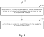
- Figure 3 is a flow diagram illustrating one example of a method 300 for maintaining a fluid ejection system, such as fluid ejection system 100 previously described and illustrated with reference to Figure 1 or fluid ejection system 200 previously described and illustrated with reference to Figure 2 .
- the fluid ejection system includes an inkjet printing system.
- method 300 includes selecting, via an operator interface, one fluid ejection device of a plurality of fluid ejection devices of the fluid ejection system.
- selecting the one fluid ejection device includes selecting the one fluid ejection device via a graphical user interface. Selecting the one fluid ejection device may include selecting one printhead assembly of a plurality of printhead assemblies.
- method 300 includes activating an indicator on or proximate the selected fluid ejection device. In one example, activating the indicator includes turning on a light emitting diode.
Landscapes
- Engineering & Computer Science (AREA)
- Theoretical Computer Science (AREA)
- Human Computer Interaction (AREA)
- Physics & Mathematics (AREA)
- General Engineering & Computer Science (AREA)
- General Physics & Mathematics (AREA)
- Ink Jet (AREA)
Claims (15)
- Système d'éjection de fluide (100), comprenant :une pluralité de dispositifs d'éjection de fluide ;une interface opérateur pour sélectionner un dispositif d'éjection de fluide ; etun dispositif de commande (130) configuré pour allumer un indicateur sur le dispositif d'éjection de fluide sélectionné pour permettre au dispositif d'éjection de fluide sélectionné d'être facilement identifié.
- Système d'éjection de fluide selon la revendication 1, dans lequel chaque indicateur comporte une diode électroluminescente.
- Système d'éjection de fluide selon la revendication 1, dans lequel l'interface opérateur comporte une interface utilisateur graphique.
- Système d'éjection de fluide selon la revendication 1, dans lequel chaque dispositif d'éjection de fluide comporte un ensemble tête d'impression.
- Système d'éjection de fluide selon la revendication 1, dans lequel le système d'éjection de fluide comporte un système d'impression à jet d'encre.
- Système d'éjection de fluide (200), comprenant :une pluralité de dispositifs d'éjection de fluide ;une interface opérateur pour sélectionner un dispositif d'éjection de fluide ; etun dispositif de commande (230) configuré pour allumer un indicateur à proximité du dispositif d'éjection de fluide sélectionné pour permettre au dispositif d'éjection de fluide sélectionné d'être facilement identifié.
- Système d'éjection de fluide selon la revendication 6, comprenant en outre : au moins une carte pilote ;dans lequel chaque dispositif d'éjection de fluide est couplé électriquement de manière amovible à l'au moins une carte pilote, etdans lequel chaque indicateur est situé sur l'au moins une carte pilote.
- Système d'éjection de fluide selon la revendication 6, dans lequel chaque indicateur comporte une diode électroluminescente.
- Système d'éjection de fluide selon la revendication 6, dans lequel l'interface opérateur comporte une interface utilisateur graphique.
- Système d'éjection de fluide selon la revendication 6, dans lequel chaque dispositif d'éjection de fluide comporte un ensemble tête d'impression.
- Procédé pour maintenir un système d'éjection de fluide, le procédé comprenant : la sélection, par l'intermédiaire d'une interface opérateur, d'un dispositif d'éjection de fluide d'une pluralité de dispositifs d'éjection de fluide du système d'éjection de fluide (100, 200) ; et
l'activation d'un indicateur sur ou à proximité du dispositif d'éjection de fluide sélectionné. - Procédé selon la revendication 11, dans lequel l'activation de l'indicateur comprend l'allumage d'une diode électroluminescente.
- Procédé selon la revendication 11, dans lequel la sélection du dispositif d'éjection de fluide comprend la sélection du dispositif d'éjection de fluide par l'intermédiaire d'une interface utilisateur graphique.
- Procédé selon la revendication 11, dans lequel la sélection du dispositif d'éjection de fluide comprend la sélection d'un ensemble tête d'impression d'une pluralité d'ensembles tête d'impression.
- Procédé selon la revendication 11, dans lequel le système d'éjection de fluide comporte un système d'impression à jet d'encre.
Applications Claiming Priority (1)
| Application Number | Priority Date | Filing Date | Title |
|---|---|---|---|
| PCT/US2017/041512 WO2019013763A1 (fr) | 2017-07-11 | 2017-07-11 | Dispositifs d'éjection de fluide avec voyants |
Publications (3)
| Publication Number | Publication Date |
|---|---|
| EP3600896A1 EP3600896A1 (fr) | 2020-02-05 |
| EP3600896A4 EP3600896A4 (fr) | 2020-11-18 |
| EP3600896B1 true EP3600896B1 (fr) | 2023-03-22 |
Family
ID=65002256
Family Applications (1)
| Application Number | Title | Priority Date | Filing Date |
|---|---|---|---|
| EP17917600.3A Active EP3600896B1 (fr) | 2017-07-11 | 2017-07-11 | Dispositifs d'éjection de fluide avec voyants |
Country Status (3)
| Country | Link |
|---|---|
| US (1) | US11642888B2 (fr) |
| EP (1) | EP3600896B1 (fr) |
| WO (1) | WO2019013763A1 (fr) |
Family Cites Families (16)
| Publication number | Priority date | Publication date | Assignee | Title |
|---|---|---|---|---|
| US5940097A (en) * | 1996-03-22 | 1999-08-17 | Brother Kogyo Kabushiki Kaisha | Arrangement for detaching a head unit from a carriage in an ink jet printer |
| US6146037A (en) | 1999-08-24 | 2000-11-14 | Hewlett-Packard Company | Method for indicating printer status |
| US6378977B1 (en) | 2000-06-30 | 2002-04-30 | Hewlett-Packard Company | System and method for conveying printer status information |
| JP2002301829A (ja) | 2001-04-04 | 2002-10-15 | Canon Inc | インクジェット記録装置 |
| US6543875B2 (en) | 2001-04-16 | 2003-04-08 | Hewlett-Packard Company | Method and apparatus for reporting printer component status |
| US6658218B2 (en) | 2001-12-28 | 2003-12-02 | Xerox Corporation | Illuminated components for guiding maintenance and repair sequence |
| US7571973B2 (en) * | 2003-03-22 | 2009-08-11 | Hewlett-Packard Development Company, L.P. | Monitoring fluid short conditions for fluid-ejection devices |
| US6869159B2 (en) | 2003-04-04 | 2005-03-22 | Hewlett-Packard Development Company, L.P. | Contamination management system and method |
| US20090135219A1 (en) | 2005-08-04 | 2009-05-28 | Roi Nathan | Method of cooling and servicing an inkjet print head array |
| US9352573B1 (en) * | 2006-01-30 | 2016-05-31 | Shahar Turgeman | Ink printing system comprising groups of inks, each group having a unique inkbase composition |
| US20080047448A1 (en) | 2006-08-28 | 2008-02-28 | Thomas G Cocklin | Printing device and method |
| EP3723014A1 (fr) * | 2012-03-29 | 2020-10-14 | Amazon Technologies Inc. | Emplacements de ramassage |
| US9830572B2 (en) | 2012-03-29 | 2017-11-28 | Amazon Technologies, Inc. | Pickup locations |
| RU129673U1 (ru) | 2012-12-17 | 2013-06-27 | Федеральное государственное унитарное предприятие "ЦентрИнформ" | Система управления удаленными печатающими устройствами |
| RU2623797C2 (ru) | 2015-07-23 | 2017-06-29 | Закрытое акционерное общество "Нордавинд" | Способ нумерации мониторов в многомониторной системе |
| US20190344560A1 (en) * | 2017-02-02 | 2019-11-14 | Hewlett-Packard Development Company, L.P. | Nozzle replacement to minimize visual discontinuities |
-
2017
- 2017-07-11 WO PCT/US2017/041512 patent/WO2019013763A1/fr unknown
- 2017-07-11 EP EP17917600.3A patent/EP3600896B1/fr active Active
- 2017-07-11 US US16/612,821 patent/US11642888B2/en active Active
Also Published As
| Publication number | Publication date |
|---|---|
| EP3600896A4 (fr) | 2020-11-18 |
| US20210276331A1 (en) | 2021-09-09 |
| EP3600896A1 (fr) | 2020-02-05 |
| US11642888B2 (en) | 2023-05-09 |
| WO2019013763A1 (fr) | 2019-01-17 |
Similar Documents
| Publication | Publication Date | Title |
|---|---|---|
| EP0863004B1 (fr) | Corrections dynamiques dans l'impression à passages multiples pour la compensation des buses à jet d'encre défaillantes | |
| US20030081024A1 (en) | Printing system adapted to shift nozzle use | |
| US7249817B2 (en) | Printer having image dividing modes | |
| CN100377879C (zh) | 喷墨容错的方法 | |
| EP1431043B1 (fr) | Procédé d'imprimer un motif d'essai et dispositif de formation d'images associé | |
| EP3600896B1 (fr) | Dispositifs d'éjection de fluide avec voyants | |
| US10343417B2 (en) | Diagnostic plot for printing system | |
| JP4788558B2 (ja) | 印刷システム、印刷方法、制御装置及びプログラム | |
| EP2569159B1 (fr) | Impression multimode | |
| JP2006027161A (ja) | 画像記録装置 | |
| US20120105530A1 (en) | Control apparatus for a liquid ejecting head, liquid ejecting apparatus, and control method for a liquid ejecting head | |
| US20120105519A1 (en) | Print cartridge identification system and method | |
| WO2020087921A1 (fr) | Procédé d'amélioration de précision d'impression longitudinale et imprimante associée | |
| JP2774641B2 (ja) | カラー記録装置 | |
| US10882344B2 (en) | Replaceable printing subassembly | |
| JP2004209977A (ja) | テストパターンの描画方法、および画像形成装置、並びにテストパターンが形成された記録媒体。 | |
| US9079397B1 (en) | Inkjet printer having switched firing of adjacent nozzles applying common color | |
| US8991978B2 (en) | Ink pen electrical interface | |
| JP2000289236A (ja) | インクジェットプリンタ | |
| CN102189809A (zh) | 液体喷射装置 | |
| JP2014040107A (ja) | 液体吐出装置 |
Legal Events
| Date | Code | Title | Description |
|---|---|---|---|
| STAA | Information on the status of an ep patent application or granted ep patent |
Free format text: STATUS: THE INTERNATIONAL PUBLICATION HAS BEEN MADE |
|
| PUAI | Public reference made under article 153(3) epc to a published international application that has entered the european phase |
Free format text: ORIGINAL CODE: 0009012 |
|
| STAA | Information on the status of an ep patent application or granted ep patent |
Free format text: STATUS: REQUEST FOR EXAMINATION WAS MADE |
|
| 17P | Request for examination filed |
Effective date: 20191031 |
|
| AK | Designated contracting states |
Kind code of ref document: A1 Designated state(s): AL AT BE BG CH CY CZ DE DK EE ES FI FR GB GR HR HU IE IS IT LI LT LU LV MC MK MT NL NO PL PT RO RS SE SI SK SM TR |
|
| AX | Request for extension of the european patent |
Extension state: BA ME |
|
| DAV | Request for validation of the european patent (deleted) | ||
| DAX | Request for extension of the european patent (deleted) | ||
| A4 | Supplementary search report drawn up and despatched |
Effective date: 20201016 |
|
| RIC1 | Information provided on ipc code assigned before grant |
Ipc: B41J 3/46 20060101ALI20201012BHEP Ipc: B41L 39/02 20060101ALI20201012BHEP Ipc: B41J 25/34 20060101ALI20201012BHEP Ipc: B41J 29/46 20060101ALI20201012BHEP Ipc: B41J 2/165 20060101ALI20201012BHEP Ipc: B41J 2/135 20060101AFI20201012BHEP |
|
| GRAP | Despatch of communication of intention to grant a patent |
Free format text: ORIGINAL CODE: EPIDOSNIGR1 |
|
| STAA | Information on the status of an ep patent application or granted ep patent |
Free format text: STATUS: GRANT OF PATENT IS INTENDED |
|
| INTG | Intention to grant announced |
Effective date: 20221201 |
|
| GRAS | Grant fee paid |
Free format text: ORIGINAL CODE: EPIDOSNIGR3 |
|
| GRAA | (expected) grant |
Free format text: ORIGINAL CODE: 0009210 |
|
| STAA | Information on the status of an ep patent application or granted ep patent |
Free format text: STATUS: THE PATENT HAS BEEN GRANTED |
|
| AK | Designated contracting states |
Kind code of ref document: B1 Designated state(s): AL AT BE BG CH CY CZ DE DK EE ES FI FR GB GR HR HU IE IS IT LI LT LU LV MC MK MT NL NO PL PT RO RS SE SI SK SM TR |
|
| REG | Reference to a national code |
Ref country code: GB Ref legal event code: FG4D |
|
| REG | Reference to a national code |
Ref country code: CH Ref legal event code: EP |
|
| REG | Reference to a national code |
Ref country code: IE Ref legal event code: FG4D |
|
| REG | Reference to a national code |
Ref country code: DE Ref legal event code: R096 Ref document number: 602017067119 Country of ref document: DE |
|
| REG | Reference to a national code |
Ref country code: AT Ref legal event code: REF Ref document number: 1555070 Country of ref document: AT Kind code of ref document: T Effective date: 20230415 |
|
| REG | Reference to a national code |
Ref country code: LT Ref legal event code: MG9D |
|
| REG | Reference to a national code |
Ref country code: NL Ref legal event code: MP Effective date: 20230322 |
|
| PG25 | Lapsed in a contracting state [announced via postgrant information from national office to epo] |
Ref country code: RS Free format text: LAPSE BECAUSE OF FAILURE TO SUBMIT A TRANSLATION OF THE DESCRIPTION OR TO PAY THE FEE WITHIN THE PRESCRIBED TIME-LIMIT Effective date: 20230322 Ref country code: NO Free format text: LAPSE BECAUSE OF FAILURE TO SUBMIT A TRANSLATION OF THE DESCRIPTION OR TO PAY THE FEE WITHIN THE PRESCRIBED TIME-LIMIT Effective date: 20230622 Ref country code: LV Free format text: LAPSE BECAUSE OF FAILURE TO SUBMIT A TRANSLATION OF THE DESCRIPTION OR TO PAY THE FEE WITHIN THE PRESCRIBED TIME-LIMIT Effective date: 20230322 Ref country code: LT Free format text: LAPSE BECAUSE OF FAILURE TO SUBMIT A TRANSLATION OF THE DESCRIPTION OR TO PAY THE FEE WITHIN THE PRESCRIBED TIME-LIMIT Effective date: 20230322 Ref country code: HR Free format text: LAPSE BECAUSE OF FAILURE TO SUBMIT A TRANSLATION OF THE DESCRIPTION OR TO PAY THE FEE WITHIN THE PRESCRIBED TIME-LIMIT Effective date: 20230322 |
|
| REG | Reference to a national code |
Ref country code: AT Ref legal event code: MK05 Ref document number: 1555070 Country of ref document: AT Kind code of ref document: T Effective date: 20230322 |
|
| PG25 | Lapsed in a contracting state [announced via postgrant information from national office to epo] |
Ref country code: SE Free format text: LAPSE BECAUSE OF FAILURE TO SUBMIT A TRANSLATION OF THE DESCRIPTION OR TO PAY THE FEE WITHIN THE PRESCRIBED TIME-LIMIT Effective date: 20230322 Ref country code: NL Free format text: LAPSE BECAUSE OF FAILURE TO SUBMIT A TRANSLATION OF THE DESCRIPTION OR TO PAY THE FEE WITHIN THE PRESCRIBED TIME-LIMIT Effective date: 20230322 Ref country code: GR Free format text: LAPSE BECAUSE OF FAILURE TO SUBMIT A TRANSLATION OF THE DESCRIPTION OR TO PAY THE FEE WITHIN THE PRESCRIBED TIME-LIMIT Effective date: 20230623 Ref country code: FI Free format text: LAPSE BECAUSE OF FAILURE TO SUBMIT A TRANSLATION OF THE DESCRIPTION OR TO PAY THE FEE WITHIN THE PRESCRIBED TIME-LIMIT Effective date: 20230322 |
|
| PG25 | Lapsed in a contracting state [announced via postgrant information from national office to epo] |
Ref country code: SM Free format text: LAPSE BECAUSE OF FAILURE TO SUBMIT A TRANSLATION OF THE DESCRIPTION OR TO PAY THE FEE WITHIN THE PRESCRIBED TIME-LIMIT Effective date: 20230322 Ref country code: RO Free format text: LAPSE BECAUSE OF FAILURE TO SUBMIT A TRANSLATION OF THE DESCRIPTION OR TO PAY THE FEE WITHIN THE PRESCRIBED TIME-LIMIT Effective date: 20230322 Ref country code: PT Free format text: LAPSE BECAUSE OF FAILURE TO SUBMIT A TRANSLATION OF THE DESCRIPTION OR TO PAY THE FEE WITHIN THE PRESCRIBED TIME-LIMIT Effective date: 20230724 Ref country code: ES Free format text: LAPSE BECAUSE OF FAILURE TO SUBMIT A TRANSLATION OF THE DESCRIPTION OR TO PAY THE FEE WITHIN THE PRESCRIBED TIME-LIMIT Effective date: 20230322 Ref country code: EE Free format text: LAPSE BECAUSE OF FAILURE TO SUBMIT A TRANSLATION OF THE DESCRIPTION OR TO PAY THE FEE WITHIN THE PRESCRIBED TIME-LIMIT Effective date: 20230322 Ref country code: AT Free format text: LAPSE BECAUSE OF FAILURE TO SUBMIT A TRANSLATION OF THE DESCRIPTION OR TO PAY THE FEE WITHIN THE PRESCRIBED TIME-LIMIT Effective date: 20230322 |
|
| PG25 | Lapsed in a contracting state [announced via postgrant information from national office to epo] |
Ref country code: SK Free format text: LAPSE BECAUSE OF FAILURE TO SUBMIT A TRANSLATION OF THE DESCRIPTION OR TO PAY THE FEE WITHIN THE PRESCRIBED TIME-LIMIT Effective date: 20230322 Ref country code: PL Free format text: LAPSE BECAUSE OF FAILURE TO SUBMIT A TRANSLATION OF THE DESCRIPTION OR TO PAY THE FEE WITHIN THE PRESCRIBED TIME-LIMIT Effective date: 20230322 Ref country code: IS Free format text: LAPSE BECAUSE OF FAILURE TO SUBMIT A TRANSLATION OF THE DESCRIPTION OR TO PAY THE FEE WITHIN THE PRESCRIBED TIME-LIMIT Effective date: 20230722 |
|
| PGFP | Annual fee paid to national office [announced via postgrant information from national office to epo] |
Ref country code: DE Payment date: 20230620 Year of fee payment: 7 |
|
| REG | Reference to a national code |
Ref country code: DE Ref legal event code: R097 Ref document number: 602017067119 Country of ref document: DE |
|
| PLBE | No opposition filed within time limit |
Free format text: ORIGINAL CODE: 0009261 |
|
| STAA | Information on the status of an ep patent application or granted ep patent |
Free format text: STATUS: NO OPPOSITION FILED WITHIN TIME LIMIT |
|
| PG25 | Lapsed in a contracting state [announced via postgrant information from national office to epo] |
Ref country code: SI Free format text: LAPSE BECAUSE OF FAILURE TO SUBMIT A TRANSLATION OF THE DESCRIPTION OR TO PAY THE FEE WITHIN THE PRESCRIBED TIME-LIMIT Effective date: 20230322 Ref country code: DK Free format text: LAPSE BECAUSE OF FAILURE TO SUBMIT A TRANSLATION OF THE DESCRIPTION OR TO PAY THE FEE WITHIN THE PRESCRIBED TIME-LIMIT Effective date: 20230322 Ref country code: CZ Free format text: LAPSE BECAUSE OF FAILURE TO SUBMIT A TRANSLATION OF THE DESCRIPTION OR TO PAY THE FEE WITHIN THE PRESCRIBED TIME-LIMIT Effective date: 20230322 |
|
| 26N | No opposition filed |
Effective date: 20240102 |
|
| PG25 | Lapsed in a contracting state [announced via postgrant information from national office to epo] |
Ref country code: MC Free format text: LAPSE BECAUSE OF FAILURE TO SUBMIT A TRANSLATION OF THE DESCRIPTION OR TO PAY THE FEE WITHIN THE PRESCRIBED TIME-LIMIT Effective date: 20230322 |
|
| PG25 | Lapsed in a contracting state [announced via postgrant information from national office to epo] |
Ref country code: MC Free format text: LAPSE BECAUSE OF FAILURE TO SUBMIT A TRANSLATION OF THE DESCRIPTION OR TO PAY THE FEE WITHIN THE PRESCRIBED TIME-LIMIT Effective date: 20230322 |
|
| REG | Reference to a national code |
Ref country code: CH Ref legal event code: PL |
|
| REG | Reference to a national code |
Ref country code: BE Ref legal event code: MM Effective date: 20230731 |
|
| PG25 | Lapsed in a contracting state [announced via postgrant information from national office to epo] |
Ref country code: LU Free format text: LAPSE BECAUSE OF NON-PAYMENT OF DUE FEES Effective date: 20230711 |
|
| GBPC | Gb: european patent ceased through non-payment of renewal fee |
Effective date: 20230711 |
|
| PG25 | Lapsed in a contracting state [announced via postgrant information from national office to epo] |
Ref country code: LU Free format text: LAPSE BECAUSE OF NON-PAYMENT OF DUE FEES Effective date: 20230711 |
|
| REG | Reference to a national code |
Ref country code: IE Ref legal event code: MM4A |
|
| PG25 | Lapsed in a contracting state [announced via postgrant information from national office to epo] |
Ref country code: CH Free format text: LAPSE BECAUSE OF NON-PAYMENT OF DUE FEES Effective date: 20230731 Ref country code: GB Free format text: LAPSE BECAUSE OF NON-PAYMENT OF DUE FEES Effective date: 20230711 |