EP3600508B1 - Ventilanordnung für eine patientenschnittstellenvorrichtung - Google Patents
Ventilanordnung für eine patientenschnittstellenvorrichtung Download PDFInfo
- Publication number
- EP3600508B1 EP3600508B1 EP18715516.3A EP18715516A EP3600508B1 EP 3600508 B1 EP3600508 B1 EP 3600508B1 EP 18715516 A EP18715516 A EP 18715516A EP 3600508 B1 EP3600508 B1 EP 3600508B1
- Authority
- EP
- European Patent Office
- Prior art keywords
- patient
- guard member
- coupling portion
- interface device
- aperture
- Prior art date
- Legal status (The legal status is an assumption and is not a legal conclusion. Google has not performed a legal analysis and makes no representation as to the accuracy of the status listed.)
- Active
Links
Images


Classifications
-
- A—HUMAN NECESSITIES
- A61—MEDICAL OR VETERINARY SCIENCE; HYGIENE
- A61M—DEVICES FOR INTRODUCING MEDIA INTO, OR ONTO, THE BODY; DEVICES FOR TRANSDUCING BODY MEDIA OR FOR TAKING MEDIA FROM THE BODY; DEVICES FOR PRODUCING OR ENDING SLEEP OR STUPOR
- A61M16/00—Devices for influencing the respiratory system of patients by gas treatment, e.g. ventilators; Tracheal tubes
- A61M16/06—Respiratory or anaesthetic masks
-
- A—HUMAN NECESSITIES
- A61—MEDICAL OR VETERINARY SCIENCE; HYGIENE
- A61M—DEVICES FOR INTRODUCING MEDIA INTO, OR ONTO, THE BODY; DEVICES FOR TRANSDUCING BODY MEDIA OR FOR TAKING MEDIA FROM THE BODY; DEVICES FOR PRODUCING OR ENDING SLEEP OR STUPOR
- A61M16/00—Devices for influencing the respiratory system of patients by gas treatment, e.g. ventilators; Tracheal tubes
- A61M16/20—Valves specially adapted to medical respiratory devices
- A61M16/208—Non-controlled one-way valves, e.g. exhalation, check, pop-off non-rebreathing valves
-
- A—HUMAN NECESSITIES
- A61—MEDICAL OR VETERINARY SCIENCE; HYGIENE
- A61M—DEVICES FOR INTRODUCING MEDIA INTO, OR ONTO, THE BODY; DEVICES FOR TRANSDUCING BODY MEDIA OR FOR TAKING MEDIA FROM THE BODY; DEVICES FOR PRODUCING OR ENDING SLEEP OR STUPOR
- A61M16/00—Devices for influencing the respiratory system of patients by gas treatment, e.g. ventilators; Tracheal tubes
- A61M16/06—Respiratory or anaesthetic masks
- A61M16/0683—Holding devices therefor
-
- A—HUMAN NECESSITIES
- A61—MEDICAL OR VETERINARY SCIENCE; HYGIENE
- A61M—DEVICES FOR INTRODUCING MEDIA INTO, OR ONTO, THE BODY; DEVICES FOR TRANSDUCING BODY MEDIA OR FOR TAKING MEDIA FROM THE BODY; DEVICES FOR PRODUCING OR ENDING SLEEP OR STUPOR
- A61M16/00—Devices for influencing the respiratory system of patients by gas treatment, e.g. ventilators; Tracheal tubes
- A61M16/08—Bellows; Connecting tubes ; Water traps; Patient circuits
- A61M16/0816—Joints or connectors
-
- A—HUMAN NECESSITIES
- A61—MEDICAL OR VETERINARY SCIENCE; HYGIENE
- A61M—DEVICES FOR INTRODUCING MEDIA INTO, OR ONTO, THE BODY; DEVICES FOR TRANSDUCING BODY MEDIA OR FOR TAKING MEDIA FROM THE BODY; DEVICES FOR PRODUCING OR ENDING SLEEP OR STUPOR
- A61M16/00—Devices for influencing the respiratory system of patients by gas treatment, e.g. ventilators; Tracheal tubes
- A61M16/08—Bellows; Connecting tubes ; Water traps; Patient circuits
- A61M16/0875—Connecting tubes
-
- A—HUMAN NECESSITIES
- A61—MEDICAL OR VETERINARY SCIENCE; HYGIENE
- A61M—DEVICES FOR INTRODUCING MEDIA INTO, OR ONTO, THE BODY; DEVICES FOR TRANSDUCING BODY MEDIA OR FOR TAKING MEDIA FROM THE BODY; DEVICES FOR PRODUCING OR ENDING SLEEP OR STUPOR
- A61M2202/00—Special media to be introduced, removed or treated
- A61M2202/02—Gases
- A61M2202/0225—Carbon oxides, e.g. Carbon dioxide
-
- F—MECHANICAL ENGINEERING; LIGHTING; HEATING; WEAPONS; BLASTING
- F16—ENGINEERING ELEMENTS AND UNITS; GENERAL MEASURES FOR PRODUCING AND MAINTAINING EFFECTIVE FUNCTIONING OF MACHINES OR INSTALLATIONS; THERMAL INSULATION IN GENERAL
- F16K—VALVES; TAPS; COCKS; ACTUATING-FLOATS; DEVICES FOR VENTING OR AERATING
- F16K15/00—Check valves
- F16K15/14—Check valves with flexible valve members
- F16K15/16—Check valves with flexible valve members with tongue-shaped laminae
-
- F—MECHANICAL ENGINEERING; LIGHTING; HEATING; WEAPONS; BLASTING
- F16—ENGINEERING ELEMENTS AND UNITS; GENERAL MEASURES FOR PRODUCING AND MAINTAINING EFFECTIVE FUNCTIONING OF MACHINES OR INSTALLATIONS; THERMAL INSULATION IN GENERAL
- F16K—VALVES; TAPS; COCKS; ACTUATING-FLOATS; DEVICES FOR VENTING OR AERATING
- F16K27/00—Construction of housing; Use of materials therefor
- F16K27/02—Construction of housing; Use of materials therefor of lift valves
- F16K27/0209—Check valves or pivoted valves
Definitions
- the present invention relates to patient interface devices.
- the present invention also relates to valve arrangements for patient interface devices.
- sleep apnea is a common example of such sleep disordered breathing suffered by millions of people throughout the world.
- One type of sleep apnea is obstructive sleep apnea (OSA), which is a condition in which sleep is repeatedly interrupted by an inability to breathe due to an obstruction of the airway; typically the upper airway or pharyngeal area. Obstruction of the airway is generally believed to be due, at least in part, to a general relaxation of the muscles which stabilize the upper airway segment, thereby allowing the tissues to collapse the airway.
- OSA obstructive sleep apnea
- sleep apnea syndrome is a central apnea, which is a cessation of respiration due to the absence of respiratory signals from the brain's respiratory center.
- An apnea condition whether obstructive, central, or mixed, which is a combination of obstructive and central, is defined as the complete or near cessation of breathing, for example a 90% or greater reduction in peak respiratory airflow.
- sleep apnea Those afflicted with sleep apnea experience sleep fragmentation and complete or nearly complete cessation of ventilation intermittently during sleep with potentially severe degrees of oxyhemoglobin desaturation. These symptoms may be translated clinically into extreme daytime sleepiness, cardiac arrhythmias, pulmonary-artery hypertension, congestive heart failure and/or cognitive dysfunction. Other consequences of sleep apnea include right ventricular dysfunction, carbon dioxide retention during wakefulness, as well as during sleep, and continuous reduced arterial oxygen tension. Sleep apnea sufferers may be at risk for excessive mortality from these factors as well as by an elevated risk for accidents while driving and/or operating potentially dangerous equipment.
- a hypopnea is typically defined as a 50% or greater reduction in the peak respiratory airflow.
- Other types of sleep disordered breathing include, without limitation, upper airway resistance syndrome (UARS) and vibration of the airway, such as vibration of the pharyngeal wall, commonly referred to as snoring.
- UARS upper airway resistance syndrome
- snoring vibration of the airway
- CPAP continuous positive air pressure
- This positive pressure effectively "splints" the airway, thereby maintaining an open passage to the lungs.
- CPAP continuous positive air pressure
- This pressure support technique is referred to as bi-level pressure support, in which the inspiratory positive airway pressure (IPAP) delivered to the patient is higher than the expiratory positive airway pressure (EPAP).
- This pressure support technique is referred to as an auto-titration type of pressure support, because the pressure support device seeks to provide a pressure to the patient that is only as high as necessary to treat the disordered breathing.
- Pressure support therapies as just described involve the placement of a patient interface device including a mask component having a soft, flexible sealing cushion on the face of the patient.
- the mask component may be, without limitation, a nasal mask that covers the patient's nose, a nasal/oral mask that covers the patient's nose and mouth, or a full face mask that covers the patient's face.
- Such patient interface devices may also employ other patient contacting components, such as forehead supports, cheek pads and chin pads.
- the patient interface device is typically secured to the patient's head by a headgear component.
- the patient interface device is connected to a gas delivery tube or conduit and interfaces the pressure support device with the airway of the patient, so that a flow of breathing gas can be delivered from the pressure/flow generating device to the airway of the patient.
- WO 2012/040791 discloses a patient interface structure for delivery of respiratory therapy to a patient, which includes a front plate configured to conform to the shape of the patient's face; a mouth cushion defining a breathing chamber and provided to the front plate and configured to seal around the patient's mouth; and a nasal cushion configured to seal the patient's nasal airways.
- the nasal cushion is supported by the mouth cushion, does not contact a bridge of the patient's nose in use, and extends at least partially into the breathing chamber.
- a patient interface system includes a patient interface structure and a patient interface structure positioning system configured to position, stabilize and secure the patient interface structure in sealing engagement with the patient's face.
- WO 2016/097941 discloses an interface device for use in delivering a flow of breathing gas to a user, the interface device comprising: a flexible cushion having a first end adapted to sealingly engage a portion of the face of a user and an opposite second end; a rigid or semi-rigid shell sealingly coupled to the second end of the cushion, the shell and cushion are structured to define an interior space with the face of the user when disposed on the face of the user, the shell including an inlet port and a first aperture, wherein the inlet port is structured to have a conduit carrying the flow of treatment gas to the interior space selectively coupled thereto, and wherein the first aperture is structured to allow the passage of ambient air into the interior space; and a first sealing member operatively coupled to the shell and positioned such that the first sealing member is movable between (i) a first state in which the first sealing member substantially seals the first aperture, and (ii) a second state in which the first sealing member does not substantially seal the first aperture, and wherein the first sealing member moves between
- Pressure support systems often include anti-asphyxiation mechanisms built into or located near the patient interface device.
- One known anti-asphyxiation mechanism involves the use of a valve member such as a flapper component located at or about an opening (i.e., an opening to ambient gas) of the pressure support system.
- the flapper component When pressure support therapy is being delivered to the patient, the flapper component is structured to block the opening.
- the flapper component is structured to be moved to an open position to allow the patient to breathe ambient gas.
- the flapper component In order to function properly, it is critical that the flapper component be able to move between these two positions (i.e., blocking an opening during pressure support therapy, and not blocking the opening when therapy is not being delivered). A potentially asphyxiating condition could result if a patient were wearing a patient interface device, pressure support therapy was not being delivered, and a flapper component was blocking its opening.
- a valve arrangement for a patient interface device for use in delivering a flow of breathing gas to an airway of a patient.
- the patient interface device includes a sealing portion adapted to sealingly engage about at least a mouth of the patient and a frame portion supporting the sealing portion and defining a cavity therein which is adapted to receive the flow of breathing gas prior to passing to the airway of the patient.
- the valve arrangement comprises a valve member having a coupling portion and a blocking portion extending from the coupling portion, the coupling portion being structured to be coupled to the frame portion, the blocking portion being structured to sealingly engage about an aperture which is defined in the frame portion and which provides a passage between the cavity and an exterior environment, the blocking portion being structured to move between (i) a first position wherein the blocking portion seals about the aperture and prevents the ambient air from passing through the aperture, and (ii) a second position wherein at least a portion of the blocking portion is spaced from the aperture, thus allowing ambient air to pass through the cavity into the aperture.
- the valve arrangement further comprises a guard member having a coupling portion and a protecting portion extending from the coupling portion, the coupling portion being structured to be coupled to the frame portion, wherein in use, when the valve member and the guard member are coupled to the frame portion, the protecting portion of the guard member is positioned and structured to be disposed between the blocking portion of the valve member and the mouth of the patient when the sealing portion is sealingly engaged about the at least a mouth of the patient.
- the blocking portion of the valve member moves from the first position toward the second position, the blocking portion moves toward the protecting portion of the guard member.
- a patient interface device for use in delivering a flow of breathing gas to an airway of a patient.
- the patient interface device comprises a sealing portion adapted to sealingly engage about at least a mouth of the patient; a frame portion supporting the sealing portion and defining a cavity therein which is adapted to receive the flow of breathing gas prior to passing to the airway of the patient; and at least one anti-asphyxia arrangement.
- the anti-asphyxia arrangement comprises an aperture defined in the frame portion, the aperture being positioned and structured to allow passage of ambient air into the cavity from the surrounding environment, a valve member having a coupling portion and a blocking portion extending from the coupling portion, the coupling portion being coupled to the frame portion, the blocking portion being structured to move between a first position wherein the blocking portion seals about the aperture and prevents the ambient air from passing through the aperture, and a second position wherein at least a portion of the blocking portion is spaced from the aperture, thus allowing ambient air to pass through the cavity into the aperture.
- the anti-asphyxia arrangement further comprises a guard member having a coupling portion and a protecting portion extending from the coupling portion, the coupling portion being coupled to the frame portion.
- the protecting portion of the guard member is positioned and structured to be disposed between the blocking portion of the valve member and the mouth of the patient when the sealing portion is sealingly engaged about the at least a mouth of the patient.
- the blocking portion of the valve member moves from the first position toward the second position, the blocking portion moves toward the protecting portion of the guard member.
- the word "unitary” means a component that is created as a single piece or unit. Under this definition, a component that includes pieces that are created separately and then coupled together as an assembled unit is not a “unitary” component or body.
- the statement that two or more parts or components "engage” one another shall mean that the parts exert a force against one another either directly or through one or more intermediate parts or components.
- the term “number” shall mean one or an integer greater than one (i.e., a plurality).
- sealingly engage shall mean elements which contact each other in a manner such that a generally air-tight seal is formed therebetween.
- magnet materials include materials that are attracted to iron or steel, e.g., a typical magnet, and a material such as iron, steel, or another magnet to which the first material is attracted. It is understood that the purpose of two “magnetic materials” in such arrangements is to have the two materials magnetically attracted to each other. Thus, two non-magnetized materials, e.g. two pieces of normal steel, are not “magnetic materials” in such arrangements.
- two or more elements which interact in an "attractive manner” are generally drawn toward each other via magnetic forces (e.g., without limitation, two magnets which are arranged having opposing poles (i.e., N-S, S-N) facing each other).
- FIG. 1 is a partially simplified view of a pressure support system 2, in accordance with one non-limiting embodiment of the disclosed concept.
- Pressure support system 2 includes a gas flow generator 4 (shown schematically), a conduit (e.g., without limitation, hose 6, shown schematically) fluidly coupled to gas flow generator 4, and a patient interface device 10.
- Gas flow generator 4 is structured to generate a flow of breathing gas to be delivered to an airway of a patient.
- Patient interface device 10 includes an elbow member 12 coupled to hose 6, a conduit 14 coupled to elbow 12, a frame portion 16 coupled to conduit 14, a sealing portion 18 supported by and extending from frame portion 16, a headgear 19 adapted to be secured to the head of the patient, and a number of clip members 70,80 each coupled to headgear 19.
- sealing portion 18 is adapted to sealingly engage about a mouth and a nose of a patient.
- frame portion 16 and sealing portion 18 are depicted as being separate elements, it is within the scope of the disclosed concept for a suitable alternative patient interface device (not shown) to employ a sealing portion and a frame portion formed as a single unitary element.
- gas flow generator 4 passes the flow of breathing gas through hose 6, elbow 12, and into conduit 14.
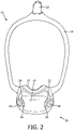
- FIG. 2 shows a front view of a portion of patient interface device 10
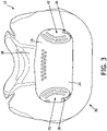
- FIG. 3 shows a rear view of a portion of patient interface device 10, each with some parts of patient interface device 10 not shown.
- Frame portion 16 defines a cavity 20 (shown in FIG. 3 ) that receives the flow of breathing gas from conduit 14 prior to passing to the airway of the patient.
- FIG. 4 shows another rear view of patient interface device 10, with additional portions of patient interface device 10 not shown in order to see hidden structures.
- patient interface device 10 includes a novel anti-asphyxia arrangement 30 for providing protection to the patient against potentially asphyxiating operating conditions.
- Anti-asphyxia arrangement 30 includes a number of apertures 32,34 (see FIGS. 2 and 6 ) defined in frame portion 16, a number of valve members 36,38, and a number of guard members 40,42. Apertures 32,34 are positioned and structured to allow passage of ambient air into cavity 20 from the surrounding environment.
- apertures 32,34 provide a safety mechanism by which the patient can breathe ambient air in conditions when pressure support therapy from gas flow generator 4 is not being delivered, such as when gas flow generator 4 ( FIG. 1 ) is turned off during a fault condition.
- valve members 36,38 provide a mechanism by which apertures 32,34 can be sealed when pressure support therapy is being delivered.
- aperture 32, valve member 36, and guard member 40 will be discussed in greater detail below.
- aperture 34, valve member 38, and guard member 42 interact in substantially the same manner as aperture 32, valve member 36, and guard member 40, respectively.
- an alternative patient interface device may have any suitable number of apertures/valve members/guard members, without departing from the scope of the disclosed concept.
- valve member 36 includes a coupling portion 44 and a generally planar blocking portion 46 extending from coupling portion 44.
- Guard member 40 includes a coupling portion 48 and a generally planar protecting portion 50 extending from coupling portion 48.
- coupling portion 44 of valve member 36 and coupling portion 48 of guard member 40 are coupled to frame portion 16.
- each of valve members 36,38 and guard members 40,42 is a unitary component made from a single piece of material.
- a suitable alternative patient interface device may employ valve members and/or guard members that are structured differently (e.g., without limitation, that are integral with frame portions rather than being separately coupled thereto).
- valve member 36 is made of a relatively flexible material (e.g., without limitation, silicone) and guard member 40 is made of a relatively rigid material (e.g., without limitation, a thermoplastic material). Accordingly, by virtue of its flexible nature, blocking portion 46 of valve member 36 is advantageously structured to move between positions.
- a relatively flexible material e.g., without limitation, silicone
- guard member 40 is made of a relatively rigid material (e.g., without limitation, a thermoplastic material). Accordingly, by virtue of its flexible nature, blocking portion 46 of valve member 36 is advantageously structured to move between positions.
- FIG. 5A shows blocking portion 46 disposed in a first position wherein blocking portion 46 seals about aperture 32 in order to prevent any ambient air from flowing therethrough. Furthermore, when pressure support therapy is being delivered, the pressurized breathing gas causes blocking portion 46 to be maintained in the first position ( FIG. 5A ). However, if/when pressure support therapy is turned off (e.g., during a potential fault condition of gas flow generator 4 ( FIG. 1 )), blocking portion 46 is structured to move from the first position ( FIG. 5A ) to a second position, which is depicted in FIG. 5B . As shown in FIG. 5B , at least a portion of blocking portion 46 is spaced from aperture 32. In one exemplary embodiment, the entire blocking portion 46 is spaced from aperture 32 in the second position. It follows that when blocking portion 46 is in the second position ( FIG. 5B ), ambient air is allowed to pass through aperture 32 into cavity 20, and thus to the airway of the patient.
- protecting portion 50 is positioned and structured to be located between blocking portion 46 of valve member 36 and the mouth of the patient when sealing portion 18 ( FIGS. 1 - 3 ) is sealingly engaged about the mouth and/or the mouth/nose of the patient.
- FIG. 5A when blocking portion 46 is in the first position, blocking portion 46 and protecting portion 50 are generally spaced from and parallel to each other. Additionally, when blocking portion 46 moves from the first position ( FIG. 5A ) toward the second position ( FIG. 5B ), blocking portion 46 moves toward protecting portion 50 of guard member 40.
- protecting portion 50 is positioned between the patient and both aperture 32 and blocking portion 46. Accordingly, it will be appreciated that protecting portion 50 advantageously functions as a barrier between the patient and valve member 36.
- protecting portion 50 which is relatively rigid, is able to substantially ensure that no portion of the face of the patient will press into blocking portion 46 of valve member 36 and prevent valve member 36 from functioning as intended.
- patients with certain facial features e.g., without limitation, relatively large lips and/or facial hair
- protecting portion 50 of guard member 40 significantly increases the likelihood that blocking portion 46 will be able to open and allow ambient air to flow through aperture 32 in such an operating condition.
- patient interface device 10 advantageously employs anti-asphyxiating features proximate the cushion. This is advantageous to patients who have existing pressure support system components (e.g., without limitation, elbow members) that are devoid of anti-asphyxiation features.
- existing pressure support system components e.g., without limitation, elbow members
- FIG. 7A and 7B are different views of valve member 36 and guard member 40, which are in the form of a valve arrangement 60.
- protecting portion 50 has a number of thru holes (a plurality of thru holes 52 are shown in FIG. 7A and FIG. 7B ).
- Thru holes 52 advantageously allow gas to flow through protecting portion 50 to push blocking portion 46 of valve member 36 towards the first position ( FIG. 5A ) in order to close aperture 32 in normal operating conditions (i.e., when pressure support therapy is being delivered).
- thru holes 52 is one method of ensuring that the flow of gas properly actuates blocking portion 46 of valve member 36.
- a suitable alternative guard member not shown to not have through holes, but have a different geometry which is still structured to promote the flow of gas to actuate blocking portion 46 of valve member 36 in all situations.
- FIG. 8A and FIG. 8B show different views of guard member 40.
- coupling portion 48 of guard member 40 has a receiving portion 54 having a thru hole.
- FIG. 9A and FIG. 9B show different views of valve member 36.
- coupling portion 44 of valve member 36 includes a first portion 62, a second portion 64 located opposite first portion 62, and a middle portion 66 between first portion 62 and second portion 64. It will be appreciated that in the exemplary embodiment, middle portion 66 of valve member 36 extends through the thru hole of receiving portion 54 of guard member 40, and first and second portions 62,64 are each structured to engage opposing sides of receiving portion 54 in order to directly couple valve member 36 to guard member 40.
- valve member 36 typically will have a tail (not shown) extending outwardly from and being integral with first portion 62 ( FIG. 9A and FIG. 9B ).
- the operator need only insert the tail (not shown) through the thru hole of receiving portion 54 ( FIG. 8A and FIG. 8B ) of guard member 40, pull until the relatively flexible first portion 62 and second portion 64 are firmly positioned on opposing sides of receiving portion 54, and then trim the tail (not shown).
- coupling portion 48 of guard member 40 further includes a body portion 56 extending from receiving portion 54.
- body portion 56 is cylindrical-shaped, and has a relatively narrow middle portion, as compared to its end portions. Accordingly, when valve arrangement 60 is installed in patient interface device 10, body portion 56 extends through and is coupled to frame portion 16.
- body portion 56 is coupled to frame portion 16 by a snap-fit mechanism, thus allowing for relatively simple and reliable assembly.
- FIG. 10 shows a top view of a clip member 70 for use with a strap of a headgear (e.g., headgear 19), and guard member 40
- FIG. 11 shows a section view of the assembly of FIG. 10
- clip member 70 has a protrusion 72 which extends into body portion 56 of guard member 40.
- the connection of protrusion 72 and body portion 56 advantageously prevents lateral movement of clip member 70 with respect to guard member 40 when the two are coupled together.
- patient interface device 10 further includes a number of magnetic materials 41,71. As shown in FIG.
- a magnetic material 41 in the shape of an annulus is provided in or on body portion 56 of guard member 40, and a magnetic material 71 in the shape of an annulus is provided in or on clip member 70.
- magnetic material 41 may be overmolded by guard member 40, and magnetic material 71 may be overmolded by clip member 70. It will be appreciated that magnetic materials 41,71 interact in an attractive manner.
- guard member 40 and clip member 70 are reliably coupled to each other by the dual mechanisms of the protrusion 72 and body portion 56 interaction, combined with the magnetic attraction of magnetic materials 41,71.
- guard member 40 advantageously functions to provide a reliable mechanism to protect against potentially asphyxiating conditions via protecting portion 50, as discussed above, as well as provides a reliable mechanism to couple clip member 70 (i.e., and thus headgear 19, FIG. 1 ) to patient interface device 10.
- the disclosed concept provides an improved (e.g., without limitation, safer and easy to manufacture/assemble) patient interface device 10 and valve arrangement 60 therefor.
- any reference signs placed between parentheses shall not be construed as limiting the claim.
- the word “comprising” or “including” does not exclude the presence of elements or steps other than those listed in a claim.
- several of these means may be embodied by one and the same item of hardware.
- the word “a” or “an” preceding an element does not exclude the presence of a plurality of such elements.
- any device claim enumerating several means several of these means may be embodied by one and the same item of hardware.
- the mere fact that certain elements are recited in mutually different dependent claims does not indicate that these elements cannot be used in combination.
Landscapes
- Health & Medical Sciences (AREA)
- Pulmonology (AREA)
- Heart & Thoracic Surgery (AREA)
- Engineering & Computer Science (AREA)
- Anesthesiology (AREA)
- Biomedical Technology (AREA)
- Emergency Medicine (AREA)
- Hematology (AREA)
- Life Sciences & Earth Sciences (AREA)
- Animal Behavior & Ethology (AREA)
- General Health & Medical Sciences (AREA)
- Public Health (AREA)
- Veterinary Medicine (AREA)
- Respiratory Apparatuses And Protective Means (AREA)
Claims (15)
- Ventilanordnung (60) für ein Patientenanschlußgerät (10) zur Verwendung bei der Abgabe eines Atemgasstroms an einen Atemweg eines Patienten, wobei das Patientenanschlußgerät einen Dichtungsabschnitt (18) umfasst, der so angepaßt ist, daß er abdichtend mindestens den Mund des Patienten umschließt, und einen Rahmenabschnitt (16), der den Dichtungsabschnitt (18) trägt und einen Hohlraum (20) darin definiert, der so angepaßt ist, daß er den Atemgasstrom aufnimmt, bevor er zum Atemweg des Patienten gelangt, wobei die Ventilanordnung umfaßt:
ein Ventilelement (36) mit einem Kupplungsabschnitt (44) und einem Sperrabschnitt (46), der sich von dem Kupplungsabschnitt erstreckt, wobei der Kupplungsabschnitt so aufgebaut ist, dass er mit dem Rahmenabschnitt gekoppelt werden kann, wobei der Sperrabschnitt so aufgebaut ist, dass er abdichtend um eine Öffnung (32) herum eingreift, die in dem Rahmenabschnitt (16) definiert ist und die einen Durchgang zwischen dem Hohlraum und einer äußeren Umgebung bereitstellt, wobei der Sperrabschnitt so aufgebaut ist, dass er sich zwischen diesen bewegt:(i) eine erste Position, in der der Sperrabschnitt die Öffnung abdichtet und verhindert, dass die Umgebungsluft durch die Öffnung strömt, und(ii) eine zweite Position, in der mindestens ein Teil des Sperrabschnitts von der Öffnung beabstandet ist, so dass Umgebungsluft durch den Hohlraum in die Öffnung strömen kann, dadurch gekennzeichnet, dass die Ventilanordnung (60) ferner Folgendes umfasst:ein Schutzelement (40) mit einem Kopplungsabschnitt (48) und einem Schutzabschnitt (50), der sich von dem Kopplungsabschnitt aus erstreckt, wobei der Kopplungsabschnitt (48) so strukturiert ist, dass er mit dem Rahmenabschnitt gekoppelt werden kann, wobei im Gebrauch, wenn das Ventilelement (36) und das Schutzelement (40) mit dem Rahmenabschnitt (16) gekoppelt sind, der Schutzabschnitt (50) des Schutzelements (40) so positioniert und strukturiert ist, dass er zwischen dem Sperrabschnitt (46) des Ventilelements (36) und demdem Mund des Patienten angeordnet ist, wenn der Dichtungsabschnitt (18) abdichtend mindestens den Mund des Patienten umschließt, undwobei, wenn sich der Sperrabschnitt (46) des Ventilelements (36) von der ersten Position in die zweite Position bewegt, sich der Sperrabschnitt (46) in Richtung des Schutzabschnitts (50) des Schutzelements bewegt. - Ventilanordnung nach Anspruch 1, wobei der Kupplungsabschnitt des Ventilelements mit dem Kupplungsabschnitt des Schutzelements gekoppelt ist.
- Ventilanordnung nach Anspruch 2, wobei der Kupplungsabschnitt des Schutzelements einen Aufnahmeabschnitt (54) mit einem Durchgangsloch aufweist; wobei der Kupplungsabschnitt des Ventilelements einen ersten Abschnitt (62), einen zweiten Abschnitt (64), der gegenüber dem ersten Abschnitt angeordnet ist, und einen mittleren Abschnitt (66) aufweist, der sich zwischen dem ersten und dem zweiten Abschnitt erstreckt; wobei sich der mittlere Abschnitt durch das Durchgangsloch des Aufnahmeabschnitts erstreckt; wobei der erste und der zweite Abschnitt jeweils so strukturiert sind, dass sie in den Aufnahmeabschnitt eingreifen, um das Ventilelement direkt mit dem Schutzelement zu koppeln.
- Ventilanordnung nach Anspruch 1, wobei der Kupplungsabschnitt des Schutzteils ferner einen Körperabschnitt (56) aufweist, der so strukturiert ist, dass er sich durch den Rahmenabschnitt erstreckt und mit diesem gekoppelt ist.
- Die Ventilanordnung nach Anspruch 4 umfasst ferner ein magnetisches Material (41), das im oder am Körperteil vorgesehen ist.
- Ventilanordnung nach Anspruch 1, wobei der Schutzabschnitt eine Anzahl von Durchgangslöchern (52) aufweist.
- Ventilanordnung nach Anspruch 1, wobei in der ersten Stellung des Sperrteils der Sperrteil und der Schutzteil im Allgemeinen parallel zueinander sind.
- Ventilanordnung nach Anspruch 1, wobei das Schutzelement aus einem starren thermoplastischen Material hergestellt ist und wobei das Ventilelement aus Silikon besteht.
- Ein Patientenanschlussgerät (10) zur Verwendung bei der Zuführung eines Atemgasflusses zu einem Atemweg eines Patienten, wobei das Patientenanschlussgerät Folgendes umfasst:(a) einen Dichtungsabschnitt (18), der so beschaffen ist, dass er abdichtend mindestens den Mund des Patienten umschließt;(b) einen Rahmenteil (16), der den Dichtungsabschnitt stützt und darin einen Hohlraum (20) definiert, der geeignet ist, den Atemgasfluss aufzunehmen, bevor er in die Atemwege des Patienten gelangt; und(c) eine Anti-Asphyxie-Anordnung (30), die Folgendes umfasst:(1) eine im Rahmenteil definierte Öffnung (32), wobei die Öffnung so angeordnet und strukturiert ist, dass sie den Durchgang von Umgebungsluft aus der Umgebung in den Hohlraum ermöglicht,(2) ein Ventilelement (36) mit einem Kupplungsabschnitt (44) und einem Sperrabschnitt (46), der sich von dem Kupplungsabschnitt aus erstreckt, wobei der Kupplungsabschnitt mit dem Rahmenabschnitt gekoppelt ist und der Sperrabschnitt so strukturiert ist, dass er sich bewegt
zwischen:(i) einer ersten Position, in der der blockierende Teil um die Öffnung herum abdichtet und verhindert, dass die Umgebungsluft durch die Öffnung strömt, und(ii) einer zweiten Position, in der mindestens ein Teil des blockierenden Teils von der Öffnung beabstandet ist, so dass Umgebungsluft durch den Hohlraum in die Öffnung strömen kann, dadurch gekennzeichnet, dass die Anti-Asphyxie-Anordnung (30) ferner Folgendes umfasst:(3) ein Schutzelement (40) mit einem Kupplungsabschnitt (48) und einem Schutzabschnitt (50), der sich von dem Kupplungsabschnitt aus erstreckt, wobei der Kupplungsabschnitt mit dem Rahmenabschnitt gekoppelt ist, wobei der Schutzabschnitt des Schutzelements so positioniert und strukturiert ist, dass er zwischen dem Sperrabschnitt des Ventilelements und dem Mund des Patienten angeordnet ist, wenn der Dichtungsabschnitt abdichtend mindestens den Mund des Patienten umschließt, und wobei, wenn sich der Sperrabschnitt des Ventilelements von der ersten Position zur zweiten Position bewegt, sich der Sperrabschnitt zum Schutzabschnitt des Schutzelements bewegt. - Patientenanschlussgerät nach Anspruch 9, wobei der Kupplungsabschnitt des Schutzteils mit dem Rahmenabschnitt durch einen Schnappverschlussmechanismus gekoppelt ist.
- Patientenanschlussgerät nach Anspruch 9, wobei der Kupplungsabschnitt des Ventilelements mit dem Kupplungsabschnitt des Schutzelements gekoppelt ist.
- Patientenanschlussgerät nach Anspruch 9, wobei der Schutzabschnitt eine Anzahl von Durchgangslöchern (52) aufweist.
- Patientenanschlussgerät nach Anspruch 9, das ferner ein Kopfband (19) und mindestens ein Klammerelement (70) umfasst; wobei das mindestens eine Klammerelement mit dem Kopfband und dem Kopplungsabschnitt des Schutzelements verbunden ist.
- Patientenanschlussgerät nach Anspruch 13, das ferner mindestens ein magnetisches Material (71) umfasst, das in oder auf dem mindestens einen Klammerelement vorgesehen ist; wobei die Anti-Asphyxie-Anordnung ferner ein magnetisches Material (41) umfasst, das in oder auf dem Kopplungsabschnitt des Schutzelements vorgesehen ist; und wobei das mindestens eine magnetische Material, das in oder auf dem mindestens einen Klammerelement vorgesehen ist, in einer anziehenden Weise mit dem magnetischen Material zusammenwirkt, das in oder auf dem Kupplungsabschnitt des Schutzelements vorgesehen ist, um das mindestens eine Klammerelement mit dem Kupplungsabschnitt des Schutzelements zu koppeln.
- Patientenanschlussgerät nach Anspruch 9, wobei der Kupplungsabschnitt des Schutzteils ferner einen Körperabschnitt (56) aufweist, der sich durch den Rahmenabschnitt erstreckt und mit diesem gekoppelt ist.
Applications Claiming Priority (2)
| Application Number | Priority Date | Filing Date | Title |
|---|---|---|---|
| US201762477608P | 2017-03-28 | 2017-03-28 | |
| PCT/EP2018/056918 WO2018177794A1 (en) | 2017-03-28 | 2018-03-20 | Valve arrangement for full face mask |
Publications (2)
| Publication Number | Publication Date |
|---|---|
| EP3600508A1 EP3600508A1 (de) | 2020-02-05 |
| EP3600508B1 true EP3600508B1 (de) | 2022-10-19 |
Family
ID=61899179
Family Applications (1)
| Application Number | Title | Priority Date | Filing Date |
|---|---|---|---|
| EP18715516.3A Active EP3600508B1 (de) | 2017-03-28 | 2018-03-20 | Ventilanordnung für eine patientenschnittstellenvorrichtung |
Country Status (5)
| Country | Link |
|---|---|
| US (1) | US11298500B2 (de) |
| EP (1) | EP3600508B1 (de) |
| JP (1) | JP7171606B2 (de) |
| CN (1) | CN110573206B (de) |
| WO (1) | WO2018177794A1 (de) |
Families Citing this family (19)
| Publication number | Priority date | Publication date | Assignee | Title |
|---|---|---|---|---|
| US10603456B2 (en) | 2011-04-15 | 2020-03-31 | Fisher & Paykel Healthcare Limited | Interface comprising a nasal sealing portion |
| BR112015026821A2 (pt) | 2013-04-26 | 2017-07-25 | Fisher & Paykel Healthcare Ltd | acessório de cabeça para máscara de respiração |
| US11419999B2 (en) | 2013-08-05 | 2022-08-23 | Fisher & Paykel Healthcare Limited | Seal for a patient interface, interface assemblies and aspects thereof |
| US11701486B2 (en) | 2014-06-17 | 2023-07-18 | Fisher & Paykel Healthcare Limited | Patient interfaces |
| USD799699S1 (en) * | 2015-10-09 | 2017-10-10 | Koninklijke Philips N.V. | Mask frame for CPAP therapy |
| SG10201913800UA (en) | 2015-09-04 | 2020-03-30 | Fisher & Paykel Healthcare Ltd | Patient interfaces |
| AU201812597S (en) * | 2017-11-02 | 2018-06-01 | Koninklijke Philips Nv | Patient interface mask for CPAP therapy |
| EP4197579B1 (de) | 2017-12-22 | 2025-01-29 | ResMed Pty Ltd | Leitungskopfbedeckungsverbinder für eine patientenschnittstelle |
| USD884153S1 (en) | 2018-04-04 | 2020-05-12 | Fisher & Paykel Healthcare Limited | Frame for a mask assembly |
| USD924388S1 (en) | 2018-07-10 | 2021-07-06 | ResMed Pty Ltd | Patient interface |
| USD942614S1 (en) | 2018-07-10 | 2022-02-01 | ResMed Pty Ltd | Combined cushion and frame module for patient interface |
| KR20200029971A (ko) * | 2018-09-11 | 2020-03-19 | 비클시스템주식회사 | 공기 유입 연결관의 자성 탈부착식 안면 마스크 |
| USD942615S1 (en) | 2018-09-12 | 2022-02-01 | ResMed Pty Ltd | Patient interface |
| US12447304B2 (en) | 2019-06-28 | 2025-10-21 | Resmed Pty, Ltd. | Tube detection systems and methods |
| CN114728145A (zh) * | 2019-09-10 | 2022-07-08 | 瑞思迈私人有限公司 | 用于呼吸相关病症的治疗系统以及用于其的患者接口和头套 |
| US12427279B2 (en) * | 2020-01-14 | 2025-09-30 | ResMed Pty Ltd | Single flow and pressure activated AAV |
| FR3113456A1 (fr) | 2020-08-20 | 2022-02-25 | Ndira Engineering | Dispositif facial de protection sanitaire |
| WO2022104432A1 (en) * | 2020-11-20 | 2022-05-27 | ResMed Pty Ltd | Vent and aav arrangement for patient interface |
| US12465711B2 (en) * | 2020-12-21 | 2025-11-11 | Koninklijke Philips N.V. | Mask with quick release frame and headgear |
Family Cites Families (22)
| Publication number | Priority date | Publication date | Assignee | Title |
|---|---|---|---|---|
| JPS5955535U (ja) * | 1982-10-01 | 1984-04-11 | 株式会社羽生田鉄工所 | 高圧室用酸素吸入バルブ |
| US5325892A (en) | 1992-05-29 | 1994-07-05 | Minnesota Mining And Manufacturing Company | Unidirectional fluid valve |
| CA2134764C (en) | 1992-05-29 | 1999-04-27 | Daniel A. Japuntich | Unidirectional fluid valve |
| NZ250105A (en) * | 1992-11-09 | 1996-07-26 | Monaghan Canadian Ltd | Inhalator mask; one-way valve opens upon exhalation |
| US5647355A (en) * | 1993-09-30 | 1997-07-15 | Respironics, Inc. | Automatic safety valve for respiratory equipment which is counter-balanced and self-adjusting |
| AUPP855099A0 (en) * | 1999-02-09 | 1999-03-04 | Resmed Limited | Gas delivery connection assembly |
| NZ783745A (en) * | 2003-12-31 | 2023-06-30 | ResMed Pty Ltd | Compact oronasal patient interface |
| GB0722247D0 (en) * | 2007-11-13 | 2007-12-27 | Intersurgical Ag | Improvements relating to anti-asphyxiation valves |
| US8365771B2 (en) * | 2009-12-16 | 2013-02-05 | 3M Innovative Properties Company | Unidirectional valves and filtering face masks comprising unidirectional valves |
| EP3231470B1 (de) | 2010-09-30 | 2023-01-11 | ResMed Pty Ltd | Maskensystem |
| EP3669920B1 (de) * | 2010-09-30 | 2024-10-30 | ResMed Pty Ltd | Patientenschnittstellensysteme |
| CN103764213B (zh) | 2011-07-08 | 2017-09-26 | 瑞思迈有限公司 | 用于患者接口系统的旋转弯管与连接器组件 |
| GB2549437B (en) * | 2011-12-09 | 2018-02-28 | Intersurgical Ag | Valve for respiratory masks |
| US10265496B2 (en) * | 2012-05-16 | 2019-04-23 | Koninklijke Philips N.V. | Anti-asphyxia valve assembly |
| WO2014003578A1 (en) * | 2012-06-27 | 2014-01-03 | Fisher & Paykel Healthcare Limited | Breathing assistance apparatus |
| NZ732754A (en) | 2013-05-14 | 2018-12-21 | ResMed Pty Ltd | Oro-nasal patient interface |
| EP2805748B1 (de) | 2013-05-24 | 2018-09-26 | Drägerwerk AG & Co. KGaA | Atemmaske mit Notatemventil |
| WO2015022629A1 (en) * | 2013-08-12 | 2015-02-19 | Koninklijke Philips N.V. | Fluid coupling member including valve member |
| WO2016067152A1 (en) | 2014-10-30 | 2016-05-06 | Koninklijke Philips N.V. | Interconnect assembly and support assembly including same |
| US10682482B2 (en) | 2014-12-17 | 2020-06-16 | Koninklijke Philips N.V. | Fresh air and anti-asphyxiation assembly |
| WO2017021836A1 (en) * | 2015-07-31 | 2017-02-09 | Fisher & Paykel Healthcare Limited | An elbow assembly of a patient interface, an anti-asphyxia valve for an elbow assembly and a connector |
| CN110035789B (zh) * | 2016-10-05 | 2022-06-10 | 费雪派克医疗保健有限公司 | 患者接口 |
-
2018
- 2018-03-20 JP JP2019553216A patent/JP7171606B2/ja active Active
- 2018-03-20 US US16/498,560 patent/US11298500B2/en active Active
- 2018-03-20 WO PCT/EP2018/056918 patent/WO2018177794A1/en not_active Ceased
- 2018-03-20 CN CN201880028102.0A patent/CN110573206B/zh active Active
- 2018-03-20 EP EP18715516.3A patent/EP3600508B1/de active Active
Also Published As
| Publication number | Publication date |
|---|---|
| US20200046933A1 (en) | 2020-02-13 |
| CN110573206A (zh) | 2019-12-13 |
| JP2020512114A (ja) | 2020-04-23 |
| EP3600508A1 (de) | 2020-02-05 |
| US11298500B2 (en) | 2022-04-12 |
| CN110573206B (zh) | 2022-07-19 |
| WO2018177794A1 (en) | 2018-10-04 |
| JP7171606B2 (ja) | 2022-11-15 |
Similar Documents
| Publication | Publication Date | Title |
|---|---|---|
| EP3600508B1 (de) | Ventilanordnung für eine patientenschnittstellenvorrichtung | |
| EP3082925B1 (de) | Anpassbares gesichtsabdichtungssegment für eine atemhilfsvorrichtung und verfahren zur anpassung | |
| US10737052B2 (en) | Fluid coupling member including valve member | |
| US20130008439A1 (en) | Elbow assembly | |
| EP3687611B1 (de) | Kissen mit vorsprung und patientenschnittstellenvorrichtung damit | |
| EP3773841B1 (de) | Einstellbarer rahmen für eine schnittstellenvorrichtung | |
| US20230233790A1 (en) | Patient interface stabilization device | |
| US10765827B2 (en) | Magnetically controlled forehead support | |
| EP3856313B1 (de) | Befeuchter mit eintrittsschutz zur verwendung in der cpap-therapie | |
| US20230201509A1 (en) | Magnetic fastening arrangements for securing patient interface devices | |
| EP3840808B1 (de) | Nasenabschnitt und patientenschnittstellenvorrichtung damit | |
| US20210178102A1 (en) | Dual slider headgear adjustment system with easy pull tabs and patient interface device including same | |
| EP3551266B1 (de) | Kissenelement, druckunterstützungssystem damit und verfahren zur herstellung davon | |
| US11724055B2 (en) | Multi-layers cushion assembly for a patient interface | |
| US11213648B2 (en) | Cushion member with engaging element |
Legal Events
| Date | Code | Title | Description |
|---|---|---|---|
| STAA | Information on the status of an ep patent application or granted ep patent |
Free format text: STATUS: UNKNOWN |
|
| STAA | Information on the status of an ep patent application or granted ep patent |
Free format text: STATUS: THE INTERNATIONAL PUBLICATION HAS BEEN MADE |
|
| PUAI | Public reference made under article 153(3) epc to a published international application that has entered the european phase |
Free format text: ORIGINAL CODE: 0009012 |
|
| STAA | Information on the status of an ep patent application or granted ep patent |
Free format text: STATUS: REQUEST FOR EXAMINATION WAS MADE |
|
| 17P | Request for examination filed |
Effective date: 20191028 |
|
| AK | Designated contracting states |
Kind code of ref document: A1 Designated state(s): AL AT BE BG CH CY CZ DE DK EE ES FI FR GB GR HR HU IE IS IT LI LT LU LV MC MK MT NL NO PL PT RO RS SE SI SK SM TR |
|
| AX | Request for extension of the european patent |
Extension state: BA ME |
|
| RAP1 | Party data changed (applicant data changed or rights of an application transferred) |
Owner name: KONINKLIJKE PHILIPS N.V. |
|
| DAV | Request for validation of the european patent (deleted) | ||
| DAX | Request for extension of the european patent (deleted) | ||
| GRAP | Despatch of communication of intention to grant a patent |
Free format text: ORIGINAL CODE: EPIDOSNIGR1 |
|
| STAA | Information on the status of an ep patent application or granted ep patent |
Free format text: STATUS: GRANT OF PATENT IS INTENDED |
|
| RIC1 | Information provided on ipc code assigned before grant |
Ipc: A61M 16/20 20060101ALI20220506BHEP Ipc: A61M 16/06 20060101AFI20220506BHEP |
|
| INTG | Intention to grant announced |
Effective date: 20220523 |
|
| GRAS | Grant fee paid |
Free format text: ORIGINAL CODE: EPIDOSNIGR3 |
|
| GRAA | (expected) grant |
Free format text: ORIGINAL CODE: 0009210 |
|
| STAA | Information on the status of an ep patent application or granted ep patent |
Free format text: STATUS: THE PATENT HAS BEEN GRANTED |
|
| AK | Designated contracting states |
Kind code of ref document: B1 Designated state(s): AL AT BE BG CH CY CZ DE DK EE ES FI FR GB GR HR HU IE IS IT LI LT LU LV MC MK MT NL NO PL PT RO RS SE SI SK SM TR |
|
| REG | Reference to a national code |
Ref country code: GB Ref legal event code: FG4D |
|
| REG | Reference to a national code |
Ref country code: CH Ref legal event code: EP |
|
| REG | Reference to a national code |
Ref country code: DE Ref legal event code: R096 Ref document number: 602018041949 Country of ref document: DE |
|
| REG | Reference to a national code |
Ref country code: IE Ref legal event code: FG4D |
|
| REG | Reference to a national code |
Ref country code: AT Ref legal event code: REF Ref document number: 1525184 Country of ref document: AT Kind code of ref document: T Effective date: 20221115 |
|
| REG | Reference to a national code |
Ref country code: LT Ref legal event code: MG9D |
|
| REG | Reference to a national code |
Ref country code: NL Ref legal event code: MP Effective date: 20221019 |
|
| REG | Reference to a national code |
Ref country code: AT Ref legal event code: MK05 Ref document number: 1525184 Country of ref document: AT Kind code of ref document: T Effective date: 20221019 |
|
| PG25 | Lapsed in a contracting state [announced via postgrant information from national office to epo] |
Ref country code: NL Free format text: LAPSE BECAUSE OF FAILURE TO SUBMIT A TRANSLATION OF THE DESCRIPTION OR TO PAY THE FEE WITHIN THE PRESCRIBED TIME-LIMIT Effective date: 20221019 |
|
| PG25 | Lapsed in a contracting state [announced via postgrant information from national office to epo] |
Ref country code: SE Free format text: LAPSE BECAUSE OF FAILURE TO SUBMIT A TRANSLATION OF THE DESCRIPTION OR TO PAY THE FEE WITHIN THE PRESCRIBED TIME-LIMIT Effective date: 20221019 Ref country code: PT Free format text: LAPSE BECAUSE OF FAILURE TO SUBMIT A TRANSLATION OF THE DESCRIPTION OR TO PAY THE FEE WITHIN THE PRESCRIBED TIME-LIMIT Effective date: 20230220 Ref country code: NO Free format text: LAPSE BECAUSE OF FAILURE TO SUBMIT A TRANSLATION OF THE DESCRIPTION OR TO PAY THE FEE WITHIN THE PRESCRIBED TIME-LIMIT Effective date: 20230119 Ref country code: LT Free format text: LAPSE BECAUSE OF FAILURE TO SUBMIT A TRANSLATION OF THE DESCRIPTION OR TO PAY THE FEE WITHIN THE PRESCRIBED TIME-LIMIT Effective date: 20221019 Ref country code: FI Free format text: LAPSE BECAUSE OF FAILURE TO SUBMIT A TRANSLATION OF THE DESCRIPTION OR TO PAY THE FEE WITHIN THE PRESCRIBED TIME-LIMIT Effective date: 20221019 Ref country code: ES Free format text: LAPSE BECAUSE OF FAILURE TO SUBMIT A TRANSLATION OF THE DESCRIPTION OR TO PAY THE FEE WITHIN THE PRESCRIBED TIME-LIMIT Effective date: 20221019 Ref country code: AT Free format text: LAPSE BECAUSE OF FAILURE TO SUBMIT A TRANSLATION OF THE DESCRIPTION OR TO PAY THE FEE WITHIN THE PRESCRIBED TIME-LIMIT Effective date: 20221019 |
|
| PG25 | Lapsed in a contracting state [announced via postgrant information from national office to epo] |
Ref country code: RS Free format text: LAPSE BECAUSE OF FAILURE TO SUBMIT A TRANSLATION OF THE DESCRIPTION OR TO PAY THE FEE WITHIN THE PRESCRIBED TIME-LIMIT Effective date: 20221019 Ref country code: PL Free format text: LAPSE BECAUSE OF FAILURE TO SUBMIT A TRANSLATION OF THE DESCRIPTION OR TO PAY THE FEE WITHIN THE PRESCRIBED TIME-LIMIT Effective date: 20221019 Ref country code: LV Free format text: LAPSE BECAUSE OF FAILURE TO SUBMIT A TRANSLATION OF THE DESCRIPTION OR TO PAY THE FEE WITHIN THE PRESCRIBED TIME-LIMIT Effective date: 20221019 Ref country code: IS Free format text: LAPSE BECAUSE OF FAILURE TO SUBMIT A TRANSLATION OF THE DESCRIPTION OR TO PAY THE FEE WITHIN THE PRESCRIBED TIME-LIMIT Effective date: 20230219 Ref country code: HR Free format text: LAPSE BECAUSE OF FAILURE TO SUBMIT A TRANSLATION OF THE DESCRIPTION OR TO PAY THE FEE WITHIN THE PRESCRIBED TIME-LIMIT Effective date: 20221019 Ref country code: GR Free format text: LAPSE BECAUSE OF FAILURE TO SUBMIT A TRANSLATION OF THE DESCRIPTION OR TO PAY THE FEE WITHIN THE PRESCRIBED TIME-LIMIT Effective date: 20230120 |
|
| REG | Reference to a national code |
Ref country code: DE Ref legal event code: R097 Ref document number: 602018041949 Country of ref document: DE |
|
| PG25 | Lapsed in a contracting state [announced via postgrant information from national office to epo] |
Ref country code: SM Free format text: LAPSE BECAUSE OF FAILURE TO SUBMIT A TRANSLATION OF THE DESCRIPTION OR TO PAY THE FEE WITHIN THE PRESCRIBED TIME-LIMIT Effective date: 20221019 Ref country code: RO Free format text: LAPSE BECAUSE OF FAILURE TO SUBMIT A TRANSLATION OF THE DESCRIPTION OR TO PAY THE FEE WITHIN THE PRESCRIBED TIME-LIMIT Effective date: 20221019 Ref country code: EE Free format text: LAPSE BECAUSE OF FAILURE TO SUBMIT A TRANSLATION OF THE DESCRIPTION OR TO PAY THE FEE WITHIN THE PRESCRIBED TIME-LIMIT Effective date: 20221019 Ref country code: DK Free format text: LAPSE BECAUSE OF FAILURE TO SUBMIT A TRANSLATION OF THE DESCRIPTION OR TO PAY THE FEE WITHIN THE PRESCRIBED TIME-LIMIT Effective date: 20221019 Ref country code: CZ Free format text: LAPSE BECAUSE OF FAILURE TO SUBMIT A TRANSLATION OF THE DESCRIPTION OR TO PAY THE FEE WITHIN THE PRESCRIBED TIME-LIMIT Effective date: 20221019 |
|
| PLBE | No opposition filed within time limit |
Free format text: ORIGINAL CODE: 0009261 |
|
| STAA | Information on the status of an ep patent application or granted ep patent |
Free format text: STATUS: NO OPPOSITION FILED WITHIN TIME LIMIT |
|
| PG25 | Lapsed in a contracting state [announced via postgrant information from national office to epo] |
Ref country code: SK Free format text: LAPSE BECAUSE OF FAILURE TO SUBMIT A TRANSLATION OF THE DESCRIPTION OR TO PAY THE FEE WITHIN THE PRESCRIBED TIME-LIMIT Effective date: 20221019 Ref country code: AL Free format text: LAPSE BECAUSE OF FAILURE TO SUBMIT A TRANSLATION OF THE DESCRIPTION OR TO PAY THE FEE WITHIN THE PRESCRIBED TIME-LIMIT Effective date: 20221019 |
|
| 26N | No opposition filed |
Effective date: 20230720 |
|
| PG25 | Lapsed in a contracting state [announced via postgrant information from national office to epo] |
Ref country code: MC Free format text: LAPSE BECAUSE OF FAILURE TO SUBMIT A TRANSLATION OF THE DESCRIPTION OR TO PAY THE FEE WITHIN THE PRESCRIBED TIME-LIMIT Effective date: 20221019 |
|
| REG | Reference to a national code |
Ref country code: CH Ref legal event code: PL |
|
| PG25 | Lapsed in a contracting state [announced via postgrant information from national office to epo] |
Ref country code: SI Free format text: LAPSE BECAUSE OF FAILURE TO SUBMIT A TRANSLATION OF THE DESCRIPTION OR TO PAY THE FEE WITHIN THE PRESCRIBED TIME-LIMIT Effective date: 20221019 |
|
| REG | Reference to a national code |
Ref country code: BE Ref legal event code: MM Effective date: 20230331 |
|
| PG25 | Lapsed in a contracting state [announced via postgrant information from national office to epo] |
Ref country code: LU Free format text: LAPSE BECAUSE OF NON-PAYMENT OF DUE FEES Effective date: 20230320 |
|
| REG | Reference to a national code |
Ref country code: IE Ref legal event code: MM4A |
|
| PG25 | Lapsed in a contracting state [announced via postgrant information from national office to epo] |
Ref country code: LI Free format text: LAPSE BECAUSE OF NON-PAYMENT OF DUE FEES Effective date: 20230331 Ref country code: IE Free format text: LAPSE BECAUSE OF NON-PAYMENT OF DUE FEES Effective date: 20230320 Ref country code: CH Free format text: LAPSE BECAUSE OF NON-PAYMENT OF DUE FEES Effective date: 20230331 |
|
| PG25 | Lapsed in a contracting state [announced via postgrant information from national office to epo] |
Ref country code: BE Free format text: LAPSE BECAUSE OF NON-PAYMENT OF DUE FEES Effective date: 20230331 |
|
| PG25 | Lapsed in a contracting state [announced via postgrant information from national office to epo] |
Ref country code: IT Free format text: LAPSE BECAUSE OF FAILURE TO SUBMIT A TRANSLATION OF THE DESCRIPTION OR TO PAY THE FEE WITHIN THE PRESCRIBED TIME-LIMIT Effective date: 20221019 |
|
| PG25 | Lapsed in a contracting state [announced via postgrant information from national office to epo] |
Ref country code: BG Free format text: LAPSE BECAUSE OF FAILURE TO SUBMIT A TRANSLATION OF THE DESCRIPTION OR TO PAY THE FEE WITHIN THE PRESCRIBED TIME-LIMIT Effective date: 20221019 |
|
| PG25 | Lapsed in a contracting state [announced via postgrant information from national office to epo] |
Ref country code: BG Free format text: LAPSE BECAUSE OF FAILURE TO SUBMIT A TRANSLATION OF THE DESCRIPTION OR TO PAY THE FEE WITHIN THE PRESCRIBED TIME-LIMIT Effective date: 20221019 |
|
| PGFP | Annual fee paid to national office [announced via postgrant information from national office to epo] |
Ref country code: DE Payment date: 20250327 Year of fee payment: 8 |
|
| PGFP | Annual fee paid to national office [announced via postgrant information from national office to epo] |
Ref country code: FR Payment date: 20250324 Year of fee payment: 8 |
|
| PGFP | Annual fee paid to national office [announced via postgrant information from national office to epo] |
Ref country code: GB Payment date: 20250325 Year of fee payment: 8 |
|
| PG25 | Lapsed in a contracting state [announced via postgrant information from national office to epo] |
Ref country code: CY Free format text: LAPSE BECAUSE OF FAILURE TO SUBMIT A TRANSLATION OF THE DESCRIPTION OR TO PAY THE FEE WITHIN THE PRESCRIBED TIME-LIMIT; INVALID AB INITIO Effective date: 20180320 |
|
| PG25 | Lapsed in a contracting state [announced via postgrant information from national office to epo] |
Ref country code: HU Free format text: LAPSE BECAUSE OF FAILURE TO SUBMIT A TRANSLATION OF THE DESCRIPTION OR TO PAY THE FEE WITHIN THE PRESCRIBED TIME-LIMIT; INVALID AB INITIO Effective date: 20180320 |
|
| PG25 | Lapsed in a contracting state [announced via postgrant information from national office to epo] |
Ref country code: TR Free format text: LAPSE BECAUSE OF FAILURE TO SUBMIT A TRANSLATION OF THE DESCRIPTION OR TO PAY THE FEE WITHIN THE PRESCRIBED TIME-LIMIT Effective date: 20221019 |