EP3600508B1 - Valve arrangement for a patient interface device - Google Patents
Valve arrangement for a patient interface device Download PDFInfo
- Publication number
- EP3600508B1 EP3600508B1 EP18715516.3A EP18715516A EP3600508B1 EP 3600508 B1 EP3600508 B1 EP 3600508B1 EP 18715516 A EP18715516 A EP 18715516A EP 3600508 B1 EP3600508 B1 EP 3600508B1
- Authority
- EP
- European Patent Office
- Prior art keywords
- patient
- guard member
- coupling portion
- interface device
- aperture
- Prior art date
- Legal status (The legal status is an assumption and is not a legal conclusion. Google has not performed a legal analysis and makes no representation as to the accuracy of the status listed.)
- Active
Links
- 230000000903 blocking effect Effects 0.000 claims description 58
- 230000008878 coupling Effects 0.000 claims description 48
- 238000010168 coupling process Methods 0.000 claims description 48
- 238000005859 coupling reaction Methods 0.000 claims description 48
- 230000029058 respiratory gaseous exchange Effects 0.000 claims description 26
- 238000007789 sealing Methods 0.000 claims description 24
- 239000012080 ambient air Substances 0.000 claims description 16
- 239000000696 magnetic material Substances 0.000 claims description 15
- 206010003497 Asphyxia Diseases 0.000 claims description 11
- 230000007246 mechanism Effects 0.000 claims description 10
- 229920001296 polysiloxane Polymers 0.000 claims description 2
- 239000012815 thermoplastic material Substances 0.000 claims description 2
- 239000007789 gas Substances 0.000 description 26
- 238000002560 therapeutic procedure Methods 0.000 description 14
- 239000000463 material Substances 0.000 description 8
- 201000002859 sleep apnea Diseases 0.000 description 6
- 206010021079 Hypopnoea Diseases 0.000 description 4
- XEEYBQQBJWHFJM-UHFFFAOYSA-N Iron Chemical compound [Fe] XEEYBQQBJWHFJM-UHFFFAOYSA-N 0.000 description 4
- 238000004519 manufacturing process Methods 0.000 description 4
- 238000000034 method Methods 0.000 description 4
- 229910000831 Steel Inorganic materials 0.000 description 3
- 230000001815 facial effect Effects 0.000 description 3
- 230000000670 limiting effect Effects 0.000 description 3
- 230000000241 respiratory effect Effects 0.000 description 3
- 239000010959 steel Substances 0.000 description 3
- CURLTUGMZLYLDI-UHFFFAOYSA-N Carbon dioxide Chemical compound O=C=O CURLTUGMZLYLDI-UHFFFAOYSA-N 0.000 description 2
- 206010063968 Upper airway resistance syndrome Diseases 0.000 description 2
- 208000008784 apnea Diseases 0.000 description 2
- 210000003128 head Anatomy 0.000 description 2
- 230000003993 interaction Effects 0.000 description 2
- 229910052742 iron Inorganic materials 0.000 description 2
- 230000000414 obstructive effect Effects 0.000 description 2
- 208000001797 obstructive sleep apnea Diseases 0.000 description 2
- 230000036961 partial effect Effects 0.000 description 2
- 230000009467 reduction Effects 0.000 description 2
- 206010007559 Cardiac failure congestive Diseases 0.000 description 1
- 208000003417 Central Sleep Apnea Diseases 0.000 description 1
- 208000007590 Disorders of Excessive Somnolence Diseases 0.000 description 1
- 206010019280 Heart failures Diseases 0.000 description 1
- 206010020772 Hypertension Diseases 0.000 description 1
- 108010064719 Oxyhemoglobins Proteins 0.000 description 1
- 206010062519 Poor quality sleep Diseases 0.000 description 1
- 208000008166 Right Ventricular Dysfunction Diseases 0.000 description 1
- 208000010340 Sleep Deprivation Diseases 0.000 description 1
- 206010041235 Snoring Diseases 0.000 description 1
- 206010041349 Somnolence Diseases 0.000 description 1
- 230000002411 adverse Effects 0.000 description 1
- 239000003570 air Substances 0.000 description 1
- 230000037007 arousal Effects 0.000 description 1
- 206010003119 arrhythmia Diseases 0.000 description 1
- QVGXLLKOCUKJST-UHFFFAOYSA-N atomic oxygen Chemical compound [O] QVGXLLKOCUKJST-UHFFFAOYSA-N 0.000 description 1
- 230000004888 barrier function Effects 0.000 description 1
- 230000008901 benefit Effects 0.000 description 1
- 210000004556 brain Anatomy 0.000 description 1
- 229910002092 carbon dioxide Inorganic materials 0.000 description 1
- 239000001569 carbon dioxide Substances 0.000 description 1
- 208000010877 cognitive disease Diseases 0.000 description 1
- 230000001419 dependent effect Effects 0.000 description 1
- 230000009977 dual effect Effects 0.000 description 1
- 230000000694 effects Effects 0.000 description 1
- 210000001061 forehead Anatomy 0.000 description 1
- 230000003434 inspiratory effect Effects 0.000 description 1
- 238000009434 installation Methods 0.000 description 1
- 210000004072 lung Anatomy 0.000 description 1
- 230000014759 maintenance of location Effects 0.000 description 1
- 230000004048 modification Effects 0.000 description 1
- 238000012986 modification Methods 0.000 description 1
- 210000003205 muscle Anatomy 0.000 description 1
- 229910052760 oxygen Inorganic materials 0.000 description 1
- 239000001301 oxygen Substances 0.000 description 1
- 210000001147 pulmonary artery Anatomy 0.000 description 1
- 230000002829 reductive effect Effects 0.000 description 1
- 210000001034 respiratory center Anatomy 0.000 description 1
- 238000002644 respiratory therapy Methods 0.000 description 1
- 230000006814 right ventricular dysfunction Effects 0.000 description 1
- 208000024891 symptom Diseases 0.000 description 1
- 210000001519 tissue Anatomy 0.000 description 1
- 238000004448 titration Methods 0.000 description 1
- 238000009423 ventilation Methods 0.000 description 1
Images


Classifications
-
- A—HUMAN NECESSITIES
- A61—MEDICAL OR VETERINARY SCIENCE; HYGIENE
- A61M—DEVICES FOR INTRODUCING MEDIA INTO, OR ONTO, THE BODY; DEVICES FOR TRANSDUCING BODY MEDIA OR FOR TAKING MEDIA FROM THE BODY; DEVICES FOR PRODUCING OR ENDING SLEEP OR STUPOR
- A61M16/00—Devices for influencing the respiratory system of patients by gas treatment, e.g. mouth-to-mouth respiration; Tracheal tubes
- A61M16/06—Respiratory or anaesthetic masks
-
- A—HUMAN NECESSITIES
- A61—MEDICAL OR VETERINARY SCIENCE; HYGIENE
- A61M—DEVICES FOR INTRODUCING MEDIA INTO, OR ONTO, THE BODY; DEVICES FOR TRANSDUCING BODY MEDIA OR FOR TAKING MEDIA FROM THE BODY; DEVICES FOR PRODUCING OR ENDING SLEEP OR STUPOR
- A61M16/00—Devices for influencing the respiratory system of patients by gas treatment, e.g. mouth-to-mouth respiration; Tracheal tubes
- A61M16/20—Valves specially adapted to medical respiratory devices
- A61M16/208—Non-controlled one-way valves, e.g. exhalation, check, pop-off non-rebreathing valves
-
- A—HUMAN NECESSITIES
- A61—MEDICAL OR VETERINARY SCIENCE; HYGIENE
- A61M—DEVICES FOR INTRODUCING MEDIA INTO, OR ONTO, THE BODY; DEVICES FOR TRANSDUCING BODY MEDIA OR FOR TAKING MEDIA FROM THE BODY; DEVICES FOR PRODUCING OR ENDING SLEEP OR STUPOR
- A61M16/00—Devices for influencing the respiratory system of patients by gas treatment, e.g. mouth-to-mouth respiration; Tracheal tubes
- A61M16/06—Respiratory or anaesthetic masks
- A61M16/0683—Holding devices therefor
-
- A—HUMAN NECESSITIES
- A61—MEDICAL OR VETERINARY SCIENCE; HYGIENE
- A61M—DEVICES FOR INTRODUCING MEDIA INTO, OR ONTO, THE BODY; DEVICES FOR TRANSDUCING BODY MEDIA OR FOR TAKING MEDIA FROM THE BODY; DEVICES FOR PRODUCING OR ENDING SLEEP OR STUPOR
- A61M16/00—Devices for influencing the respiratory system of patients by gas treatment, e.g. mouth-to-mouth respiration; Tracheal tubes
- A61M16/08—Bellows; Connecting tubes ; Water traps; Patient circuits
- A61M16/0816—Joints or connectors
-
- A—HUMAN NECESSITIES
- A61—MEDICAL OR VETERINARY SCIENCE; HYGIENE
- A61M—DEVICES FOR INTRODUCING MEDIA INTO, OR ONTO, THE BODY; DEVICES FOR TRANSDUCING BODY MEDIA OR FOR TAKING MEDIA FROM THE BODY; DEVICES FOR PRODUCING OR ENDING SLEEP OR STUPOR
- A61M16/00—Devices for influencing the respiratory system of patients by gas treatment, e.g. mouth-to-mouth respiration; Tracheal tubes
- A61M16/08—Bellows; Connecting tubes ; Water traps; Patient circuits
- A61M16/0875—Connecting tubes
-
- A—HUMAN NECESSITIES
- A61—MEDICAL OR VETERINARY SCIENCE; HYGIENE
- A61M—DEVICES FOR INTRODUCING MEDIA INTO, OR ONTO, THE BODY; DEVICES FOR TRANSDUCING BODY MEDIA OR FOR TAKING MEDIA FROM THE BODY; DEVICES FOR PRODUCING OR ENDING SLEEP OR STUPOR
- A61M2202/00—Special media to be introduced, removed or treated
- A61M2202/02—Gases
- A61M2202/0225—Carbon oxides, e.g. Carbon dioxide
-
- F—MECHANICAL ENGINEERING; LIGHTING; HEATING; WEAPONS; BLASTING
- F16—ENGINEERING ELEMENTS AND UNITS; GENERAL MEASURES FOR PRODUCING AND MAINTAINING EFFECTIVE FUNCTIONING OF MACHINES OR INSTALLATIONS; THERMAL INSULATION IN GENERAL
- F16K—VALVES; TAPS; COCKS; ACTUATING-FLOATS; DEVICES FOR VENTING OR AERATING
- F16K15/00—Check valves
- F16K15/14—Check valves with flexible valve members
- F16K15/16—Check valves with flexible valve members with tongue-shaped laminae
-
- F—MECHANICAL ENGINEERING; LIGHTING; HEATING; WEAPONS; BLASTING
- F16—ENGINEERING ELEMENTS AND UNITS; GENERAL MEASURES FOR PRODUCING AND MAINTAINING EFFECTIVE FUNCTIONING OF MACHINES OR INSTALLATIONS; THERMAL INSULATION IN GENERAL
- F16K—VALVES; TAPS; COCKS; ACTUATING-FLOATS; DEVICES FOR VENTING OR AERATING
- F16K27/00—Construction of housing; Use of materials therefor
- F16K27/02—Construction of housing; Use of materials therefor of lift valves
- F16K27/0209—Check valves or pivoted valves
Definitions
- the present invention relates to patient interface devices.
- the present invention also relates to valve arrangements for patient interface devices.
- sleep apnea is a common example of such sleep disordered breathing suffered by millions of people throughout the world.
- One type of sleep apnea is obstructive sleep apnea (OSA), which is a condition in which sleep is repeatedly interrupted by an inability to breathe due to an obstruction of the airway; typically the upper airway or pharyngeal area. Obstruction of the airway is generally believed to be due, at least in part, to a general relaxation of the muscles which stabilize the upper airway segment, thereby allowing the tissues to collapse the airway.
- OSA obstructive sleep apnea
- sleep apnea syndrome is a central apnea, which is a cessation of respiration due to the absence of respiratory signals from the brain's respiratory center.
- An apnea condition whether obstructive, central, or mixed, which is a combination of obstructive and central, is defined as the complete or near cessation of breathing, for example a 90% or greater reduction in peak respiratory airflow.
- sleep apnea Those afflicted with sleep apnea experience sleep fragmentation and complete or nearly complete cessation of ventilation intermittently during sleep with potentially severe degrees of oxyhemoglobin desaturation. These symptoms may be translated clinically into extreme daytime sleepiness, cardiac arrhythmias, pulmonary-artery hypertension, congestive heart failure and/or cognitive dysfunction. Other consequences of sleep apnea include right ventricular dysfunction, carbon dioxide retention during wakefulness, as well as during sleep, and continuous reduced arterial oxygen tension. Sleep apnea sufferers may be at risk for excessive mortality from these factors as well as by an elevated risk for accidents while driving and/or operating potentially dangerous equipment.
- a hypopnea is typically defined as a 50% or greater reduction in the peak respiratory airflow.
- Other types of sleep disordered breathing include, without limitation, upper airway resistance syndrome (UARS) and vibration of the airway, such as vibration of the pharyngeal wall, commonly referred to as snoring.
- UARS upper airway resistance syndrome
- snoring vibration of the airway
- CPAP continuous positive air pressure
- This positive pressure effectively "splints" the airway, thereby maintaining an open passage to the lungs.
- CPAP continuous positive air pressure
- This pressure support technique is referred to as bi-level pressure support, in which the inspiratory positive airway pressure (IPAP) delivered to the patient is higher than the expiratory positive airway pressure (EPAP).
- This pressure support technique is referred to as an auto-titration type of pressure support, because the pressure support device seeks to provide a pressure to the patient that is only as high as necessary to treat the disordered breathing.
- Pressure support therapies as just described involve the placement of a patient interface device including a mask component having a soft, flexible sealing cushion on the face of the patient.
- the mask component may be, without limitation, a nasal mask that covers the patient's nose, a nasal/oral mask that covers the patient's nose and mouth, or a full face mask that covers the patient's face.
- Such patient interface devices may also employ other patient contacting components, such as forehead supports, cheek pads and chin pads.
- the patient interface device is typically secured to the patient's head by a headgear component.
- the patient interface device is connected to a gas delivery tube or conduit and interfaces the pressure support device with the airway of the patient, so that a flow of breathing gas can be delivered from the pressure/flow generating device to the airway of the patient.
- WO 2012/040791 discloses a patient interface structure for delivery of respiratory therapy to a patient, which includes a front plate configured to conform to the shape of the patient's face; a mouth cushion defining a breathing chamber and provided to the front plate and configured to seal around the patient's mouth; and a nasal cushion configured to seal the patient's nasal airways.
- the nasal cushion is supported by the mouth cushion, does not contact a bridge of the patient's nose in use, and extends at least partially into the breathing chamber.
- a patient interface system includes a patient interface structure and a patient interface structure positioning system configured to position, stabilize and secure the patient interface structure in sealing engagement with the patient's face.
- WO 2016/097941 discloses an interface device for use in delivering a flow of breathing gas to a user, the interface device comprising: a flexible cushion having a first end adapted to sealingly engage a portion of the face of a user and an opposite second end; a rigid or semi-rigid shell sealingly coupled to the second end of the cushion, the shell and cushion are structured to define an interior space with the face of the user when disposed on the face of the user, the shell including an inlet port and a first aperture, wherein the inlet port is structured to have a conduit carrying the flow of treatment gas to the interior space selectively coupled thereto, and wherein the first aperture is structured to allow the passage of ambient air into the interior space; and a first sealing member operatively coupled to the shell and positioned such that the first sealing member is movable between (i) a first state in which the first sealing member substantially seals the first aperture, and (ii) a second state in which the first sealing member does not substantially seal the first aperture, and wherein the first sealing member moves between
- Pressure support systems often include anti-asphyxiation mechanisms built into or located near the patient interface device.
- One known anti-asphyxiation mechanism involves the use of a valve member such as a flapper component located at or about an opening (i.e., an opening to ambient gas) of the pressure support system.
- the flapper component When pressure support therapy is being delivered to the patient, the flapper component is structured to block the opening.
- the flapper component is structured to be moved to an open position to allow the patient to breathe ambient gas.
- the flapper component In order to function properly, it is critical that the flapper component be able to move between these two positions (i.e., blocking an opening during pressure support therapy, and not blocking the opening when therapy is not being delivered). A potentially asphyxiating condition could result if a patient were wearing a patient interface device, pressure support therapy was not being delivered, and a flapper component was blocking its opening.
- a valve arrangement for a patient interface device for use in delivering a flow of breathing gas to an airway of a patient.
- the patient interface device includes a sealing portion adapted to sealingly engage about at least a mouth of the patient and a frame portion supporting the sealing portion and defining a cavity therein which is adapted to receive the flow of breathing gas prior to passing to the airway of the patient.
- the valve arrangement comprises a valve member having a coupling portion and a blocking portion extending from the coupling portion, the coupling portion being structured to be coupled to the frame portion, the blocking portion being structured to sealingly engage about an aperture which is defined in the frame portion and which provides a passage between the cavity and an exterior environment, the blocking portion being structured to move between (i) a first position wherein the blocking portion seals about the aperture and prevents the ambient air from passing through the aperture, and (ii) a second position wherein at least a portion of the blocking portion is spaced from the aperture, thus allowing ambient air to pass through the cavity into the aperture.
- the valve arrangement further comprises a guard member having a coupling portion and a protecting portion extending from the coupling portion, the coupling portion being structured to be coupled to the frame portion, wherein in use, when the valve member and the guard member are coupled to the frame portion, the protecting portion of the guard member is positioned and structured to be disposed between the blocking portion of the valve member and the mouth of the patient when the sealing portion is sealingly engaged about the at least a mouth of the patient.
- the blocking portion of the valve member moves from the first position toward the second position, the blocking portion moves toward the protecting portion of the guard member.
- a patient interface device for use in delivering a flow of breathing gas to an airway of a patient.
- the patient interface device comprises a sealing portion adapted to sealingly engage about at least a mouth of the patient; a frame portion supporting the sealing portion and defining a cavity therein which is adapted to receive the flow of breathing gas prior to passing to the airway of the patient; and at least one anti-asphyxia arrangement.
- the anti-asphyxia arrangement comprises an aperture defined in the frame portion, the aperture being positioned and structured to allow passage of ambient air into the cavity from the surrounding environment, a valve member having a coupling portion and a blocking portion extending from the coupling portion, the coupling portion being coupled to the frame portion, the blocking portion being structured to move between a first position wherein the blocking portion seals about the aperture and prevents the ambient air from passing through the aperture, and a second position wherein at least a portion of the blocking portion is spaced from the aperture, thus allowing ambient air to pass through the cavity into the aperture.
- the anti-asphyxia arrangement further comprises a guard member having a coupling portion and a protecting portion extending from the coupling portion, the coupling portion being coupled to the frame portion.
- the protecting portion of the guard member is positioned and structured to be disposed between the blocking portion of the valve member and the mouth of the patient when the sealing portion is sealingly engaged about the at least a mouth of the patient.
- the blocking portion of the valve member moves from the first position toward the second position, the blocking portion moves toward the protecting portion of the guard member.
- the word "unitary” means a component that is created as a single piece or unit. Under this definition, a component that includes pieces that are created separately and then coupled together as an assembled unit is not a “unitary” component or body.
- the statement that two or more parts or components "engage” one another shall mean that the parts exert a force against one another either directly or through one or more intermediate parts or components.
- the term “number” shall mean one or an integer greater than one (i.e., a plurality).
- sealingly engage shall mean elements which contact each other in a manner such that a generally air-tight seal is formed therebetween.
- magnet materials include materials that are attracted to iron or steel, e.g., a typical magnet, and a material such as iron, steel, or another magnet to which the first material is attracted. It is understood that the purpose of two “magnetic materials” in such arrangements is to have the two materials magnetically attracted to each other. Thus, two non-magnetized materials, e.g. two pieces of normal steel, are not “magnetic materials” in such arrangements.
- two or more elements which interact in an "attractive manner” are generally drawn toward each other via magnetic forces (e.g., without limitation, two magnets which are arranged having opposing poles (i.e., N-S, S-N) facing each other).
- FIG. 1 is a partially simplified view of a pressure support system 2, in accordance with one non-limiting embodiment of the disclosed concept.
- Pressure support system 2 includes a gas flow generator 4 (shown schematically), a conduit (e.g., without limitation, hose 6, shown schematically) fluidly coupled to gas flow generator 4, and a patient interface device 10.
- Gas flow generator 4 is structured to generate a flow of breathing gas to be delivered to an airway of a patient.
- Patient interface device 10 includes an elbow member 12 coupled to hose 6, a conduit 14 coupled to elbow 12, a frame portion 16 coupled to conduit 14, a sealing portion 18 supported by and extending from frame portion 16, a headgear 19 adapted to be secured to the head of the patient, and a number of clip members 70,80 each coupled to headgear 19.
- sealing portion 18 is adapted to sealingly engage about a mouth and a nose of a patient.
- frame portion 16 and sealing portion 18 are depicted as being separate elements, it is within the scope of the disclosed concept for a suitable alternative patient interface device (not shown) to employ a sealing portion and a frame portion formed as a single unitary element.
- gas flow generator 4 passes the flow of breathing gas through hose 6, elbow 12, and into conduit 14.
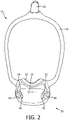
- FIG. 2 shows a front view of a portion of patient interface device 10
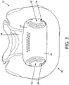
- FIG. 3 shows a rear view of a portion of patient interface device 10, each with some parts of patient interface device 10 not shown.
- Frame portion 16 defines a cavity 20 (shown in FIG. 3 ) that receives the flow of breathing gas from conduit 14 prior to passing to the airway of the patient.
- FIG. 4 shows another rear view of patient interface device 10, with additional portions of patient interface device 10 not shown in order to see hidden structures.
- patient interface device 10 includes a novel anti-asphyxia arrangement 30 for providing protection to the patient against potentially asphyxiating operating conditions.
- Anti-asphyxia arrangement 30 includes a number of apertures 32,34 (see FIGS. 2 and 6 ) defined in frame portion 16, a number of valve members 36,38, and a number of guard members 40,42. Apertures 32,34 are positioned and structured to allow passage of ambient air into cavity 20 from the surrounding environment.
- apertures 32,34 provide a safety mechanism by which the patient can breathe ambient air in conditions when pressure support therapy from gas flow generator 4 is not being delivered, such as when gas flow generator 4 ( FIG. 1 ) is turned off during a fault condition.
- valve members 36,38 provide a mechanism by which apertures 32,34 can be sealed when pressure support therapy is being delivered.
- aperture 32, valve member 36, and guard member 40 will be discussed in greater detail below.
- aperture 34, valve member 38, and guard member 42 interact in substantially the same manner as aperture 32, valve member 36, and guard member 40, respectively.
- an alternative patient interface device may have any suitable number of apertures/valve members/guard members, without departing from the scope of the disclosed concept.
- valve member 36 includes a coupling portion 44 and a generally planar blocking portion 46 extending from coupling portion 44.
- Guard member 40 includes a coupling portion 48 and a generally planar protecting portion 50 extending from coupling portion 48.
- coupling portion 44 of valve member 36 and coupling portion 48 of guard member 40 are coupled to frame portion 16.
- each of valve members 36,38 and guard members 40,42 is a unitary component made from a single piece of material.
- a suitable alternative patient interface device may employ valve members and/or guard members that are structured differently (e.g., without limitation, that are integral with frame portions rather than being separately coupled thereto).
- valve member 36 is made of a relatively flexible material (e.g., without limitation, silicone) and guard member 40 is made of a relatively rigid material (e.g., without limitation, a thermoplastic material). Accordingly, by virtue of its flexible nature, blocking portion 46 of valve member 36 is advantageously structured to move between positions.
- a relatively flexible material e.g., without limitation, silicone
- guard member 40 is made of a relatively rigid material (e.g., without limitation, a thermoplastic material). Accordingly, by virtue of its flexible nature, blocking portion 46 of valve member 36 is advantageously structured to move between positions.
- FIG. 5A shows blocking portion 46 disposed in a first position wherein blocking portion 46 seals about aperture 32 in order to prevent any ambient air from flowing therethrough. Furthermore, when pressure support therapy is being delivered, the pressurized breathing gas causes blocking portion 46 to be maintained in the first position ( FIG. 5A ). However, if/when pressure support therapy is turned off (e.g., during a potential fault condition of gas flow generator 4 ( FIG. 1 )), blocking portion 46 is structured to move from the first position ( FIG. 5A ) to a second position, which is depicted in FIG. 5B . As shown in FIG. 5B , at least a portion of blocking portion 46 is spaced from aperture 32. In one exemplary embodiment, the entire blocking portion 46 is spaced from aperture 32 in the second position. It follows that when blocking portion 46 is in the second position ( FIG. 5B ), ambient air is allowed to pass through aperture 32 into cavity 20, and thus to the airway of the patient.
- protecting portion 50 is positioned and structured to be located between blocking portion 46 of valve member 36 and the mouth of the patient when sealing portion 18 ( FIGS. 1 - 3 ) is sealingly engaged about the mouth and/or the mouth/nose of the patient.
- FIG. 5A when blocking portion 46 is in the first position, blocking portion 46 and protecting portion 50 are generally spaced from and parallel to each other. Additionally, when blocking portion 46 moves from the first position ( FIG. 5A ) toward the second position ( FIG. 5B ), blocking portion 46 moves toward protecting portion 50 of guard member 40.
- protecting portion 50 is positioned between the patient and both aperture 32 and blocking portion 46. Accordingly, it will be appreciated that protecting portion 50 advantageously functions as a barrier between the patient and valve member 36.
- protecting portion 50 which is relatively rigid, is able to substantially ensure that no portion of the face of the patient will press into blocking portion 46 of valve member 36 and prevent valve member 36 from functioning as intended.
- patients with certain facial features e.g., without limitation, relatively large lips and/or facial hair
- protecting portion 50 of guard member 40 significantly increases the likelihood that blocking portion 46 will be able to open and allow ambient air to flow through aperture 32 in such an operating condition.
- patient interface device 10 advantageously employs anti-asphyxiating features proximate the cushion. This is advantageous to patients who have existing pressure support system components (e.g., without limitation, elbow members) that are devoid of anti-asphyxiation features.
- existing pressure support system components e.g., without limitation, elbow members
- FIG. 7A and 7B are different views of valve member 36 and guard member 40, which are in the form of a valve arrangement 60.
- protecting portion 50 has a number of thru holes (a plurality of thru holes 52 are shown in FIG. 7A and FIG. 7B ).
- Thru holes 52 advantageously allow gas to flow through protecting portion 50 to push blocking portion 46 of valve member 36 towards the first position ( FIG. 5A ) in order to close aperture 32 in normal operating conditions (i.e., when pressure support therapy is being delivered).
- thru holes 52 is one method of ensuring that the flow of gas properly actuates blocking portion 46 of valve member 36.
- a suitable alternative guard member not shown to not have through holes, but have a different geometry which is still structured to promote the flow of gas to actuate blocking portion 46 of valve member 36 in all situations.
- FIG. 8A and FIG. 8B show different views of guard member 40.
- coupling portion 48 of guard member 40 has a receiving portion 54 having a thru hole.
- FIG. 9A and FIG. 9B show different views of valve member 36.
- coupling portion 44 of valve member 36 includes a first portion 62, a second portion 64 located opposite first portion 62, and a middle portion 66 between first portion 62 and second portion 64. It will be appreciated that in the exemplary embodiment, middle portion 66 of valve member 36 extends through the thru hole of receiving portion 54 of guard member 40, and first and second portions 62,64 are each structured to engage opposing sides of receiving portion 54 in order to directly couple valve member 36 to guard member 40.
- valve member 36 typically will have a tail (not shown) extending outwardly from and being integral with first portion 62 ( FIG. 9A and FIG. 9B ).
- the operator need only insert the tail (not shown) through the thru hole of receiving portion 54 ( FIG. 8A and FIG. 8B ) of guard member 40, pull until the relatively flexible first portion 62 and second portion 64 are firmly positioned on opposing sides of receiving portion 54, and then trim the tail (not shown).
- coupling portion 48 of guard member 40 further includes a body portion 56 extending from receiving portion 54.
- body portion 56 is cylindrical-shaped, and has a relatively narrow middle portion, as compared to its end portions. Accordingly, when valve arrangement 60 is installed in patient interface device 10, body portion 56 extends through and is coupled to frame portion 16.
- body portion 56 is coupled to frame portion 16 by a snap-fit mechanism, thus allowing for relatively simple and reliable assembly.
- FIG. 10 shows a top view of a clip member 70 for use with a strap of a headgear (e.g., headgear 19), and guard member 40
- FIG. 11 shows a section view of the assembly of FIG. 10
- clip member 70 has a protrusion 72 which extends into body portion 56 of guard member 40.
- the connection of protrusion 72 and body portion 56 advantageously prevents lateral movement of clip member 70 with respect to guard member 40 when the two are coupled together.
- patient interface device 10 further includes a number of magnetic materials 41,71. As shown in FIG.
- a magnetic material 41 in the shape of an annulus is provided in or on body portion 56 of guard member 40, and a magnetic material 71 in the shape of an annulus is provided in or on clip member 70.
- magnetic material 41 may be overmolded by guard member 40, and magnetic material 71 may be overmolded by clip member 70. It will be appreciated that magnetic materials 41,71 interact in an attractive manner.
- guard member 40 and clip member 70 are reliably coupled to each other by the dual mechanisms of the protrusion 72 and body portion 56 interaction, combined with the magnetic attraction of magnetic materials 41,71.
- guard member 40 advantageously functions to provide a reliable mechanism to protect against potentially asphyxiating conditions via protecting portion 50, as discussed above, as well as provides a reliable mechanism to couple clip member 70 (i.e., and thus headgear 19, FIG. 1 ) to patient interface device 10.
- the disclosed concept provides an improved (e.g., without limitation, safer and easy to manufacture/assemble) patient interface device 10 and valve arrangement 60 therefor.
- any reference signs placed between parentheses shall not be construed as limiting the claim.
- the word “comprising” or “including” does not exclude the presence of elements or steps other than those listed in a claim.
- several of these means may be embodied by one and the same item of hardware.
- the word “a” or “an” preceding an element does not exclude the presence of a plurality of such elements.
- any device claim enumerating several means several of these means may be embodied by one and the same item of hardware.
- the mere fact that certain elements are recited in mutually different dependent claims does not indicate that these elements cannot be used in combination.
Description
- This patent application claims the priority benefit under 35 U.S.C. § 119(e) of
U.S. Provisional Application No. 62/477,608, filed on March 28, 2017 - The present invention relates to patient interface devices. The present invention also relates to valve arrangements for patient interface devices.
- Many individuals suffer from disordered breathing during sleep. Sleep apnea is a common example of such sleep disordered breathing suffered by millions of people throughout the world. One type of sleep apnea is obstructive sleep apnea (OSA), which is a condition in which sleep is repeatedly interrupted by an inability to breathe due to an obstruction of the airway; typically the upper airway or pharyngeal area. Obstruction of the airway is generally believed to be due, at least in part, to a general relaxation of the muscles which stabilize the upper airway segment, thereby allowing the tissues to collapse the airway. Another type of sleep apnea syndrome is a central apnea, which is a cessation of respiration due to the absence of respiratory signals from the brain's respiratory center. An apnea condition, whether obstructive, central, or mixed, which is a combination of obstructive and central, is defined as the complete or near cessation of breathing, for example a 90% or greater reduction in peak respiratory airflow.
- Those afflicted with sleep apnea experience sleep fragmentation and complete or nearly complete cessation of ventilation intermittently during sleep with potentially severe degrees of oxyhemoglobin desaturation. These symptoms may be translated clinically into extreme daytime sleepiness, cardiac arrhythmias, pulmonary-artery hypertension, congestive heart failure and/or cognitive dysfunction. Other consequences of sleep apnea include right ventricular dysfunction, carbon dioxide retention during wakefulness, as well as during sleep, and continuous reduced arterial oxygen tension. Sleep apnea sufferers may be at risk for excessive mortality from these factors as well as by an elevated risk for accidents while driving and/or operating potentially dangerous equipment.
- Even if a patient does not suffer from a complete or nearly complete obstruction of the airway, it is also known that adverse effects, such as arousals from sleep, can occur where there is only a partial obstruction of the airway. Partial obstruction of the airway typically results in shallow breathing referred to as a hypopnea. A hypopnea is typically defined as a 50% or greater reduction in the peak respiratory airflow. Other types of sleep disordered breathing include, without limitation, upper airway resistance syndrome (UARS) and vibration of the airway, such as vibration of the pharyngeal wall, commonly referred to as snoring.
- It is well known to treat sleep disordered breathing by applying a continuous positive air pressure (CPAP) to the patient's airway. This positive pressure effectively "splints" the airway, thereby maintaining an open passage to the lungs. It is also known to provide a positive pressure therapy in which the pressure of gas delivered to the patient varies with the patient's breathing cycle, or varies with the patient's breathing effort, to increase the comfort to the patient. This pressure support technique is referred to as bi-level pressure support, in which the inspiratory positive airway pressure (IPAP) delivered to the patient is higher than the expiratory positive airway pressure (EPAP). It is further known to provide a positive pressure therapy in which the pressure is automatically adjusted based on the detected conditions of the patient, such as whether the patient is experiencing an apnea and/or hypopnea. This pressure support technique is referred to as an auto-titration type of pressure support, because the pressure support device seeks to provide a pressure to the patient that is only as high as necessary to treat the disordered breathing.
- Pressure support therapies as just described involve the placement of a patient interface device including a mask component having a soft, flexible sealing cushion on the face of the patient. The mask component may be, without limitation, a nasal mask that covers the patient's nose, a nasal/oral mask that covers the patient's nose and mouth, or a full face mask that covers the patient's face. Such patient interface devices may also employ other patient contacting components, such as forehead supports, cheek pads and chin pads. The patient interface device is typically secured to the patient's head by a headgear component. The patient interface device is connected to a gas delivery tube or conduit and interfaces the pressure support device with the airway of the patient, so that a flow of breathing gas can be delivered from the pressure/flow generating device to the airway of the patient.
-
WO 2012/040791 discloses a patient interface structure for delivery of respiratory therapy to a patient, which includes a front plate configured to conform to the shape of the patient's face; a mouth cushion defining a breathing chamber and provided to the front plate and configured to seal around the patient's mouth; and a nasal cushion configured to seal the patient's nasal airways. The nasal cushion is supported by the mouth cushion, does not contact a bridge of the patient's nose in use, and extends at least partially into the breathing chamber. A patient interface system includes a patient interface structure and a patient interface structure positioning system configured to position, stabilize and secure the patient interface structure in sealing engagement with the patient's face. -
WO 2016/097941 discloses an interface device for use in delivering a flow of breathing gas to a user, the interface device comprising: a flexible cushion having a first end adapted to sealingly engage a portion of the face of a user and an opposite second end; a rigid or semi-rigid shell sealingly coupled to the second end of the cushion, the shell and cushion are structured to define an interior space with the face of the user when disposed on the face of the user, the shell including an inlet port and a first aperture, wherein the inlet port is structured to have a conduit carrying the flow of treatment gas to the interior space selectively coupled thereto, and wherein the first aperture is structured to allow the passage of ambient air into the interior space; and a first sealing member operatively coupled to the shell and positioned such that the first sealing member is movable between (i) a first state in which the first sealing member substantially seals the first aperture, and (ii) a second state in which the first sealing member does not substantially seal the first aperture, and wherein the first sealing member moves between the first state and the second state responsive to breathing of the patient. - Pressure support systems often include anti-asphyxiation mechanisms built into or located near the patient interface device. One known anti-asphyxiation mechanism involves the use of a valve member such as a flapper component located at or about an opening (i.e., an opening to ambient gas) of the pressure support system. When pressure support therapy is being delivered to the patient, the flapper component is structured to block the opening. However, when pressure support therapy is not being delivered to the patient, such as during a fault condition or when the patient is otherwise wearing the patient interface device but the gas flow generator is not turned on, the flapper component is structured to be moved to an open position to allow the patient to breathe ambient gas. In order to function properly, it is critical that the flapper component be able to move between these two positions (i.e., blocking an opening during pressure support therapy, and not blocking the opening when therapy is not being delivered). A potentially asphyxiating condition could result if a patient were wearing a patient interface device, pressure support therapy was not being delivered, and a flapper component was blocking its opening.
- Accordingly, it is an object of the present invention to provide an improved patient interface device and valve arrangement for the same.
- As one aspect of the disclosed concept, a valve arrangement is provided for a patient interface device for use in delivering a flow of breathing gas to an airway of a patient. The patient interface device includes a sealing portion adapted to sealingly engage about at least a mouth of the patient and a frame portion supporting the sealing portion and defining a cavity therein which is adapted to receive the flow of breathing gas prior to passing to the airway of the patient. The valve arrangement comprises a valve member having a coupling portion and a blocking portion extending from the coupling portion, the coupling portion being structured to be coupled to the frame portion, the blocking portion being structured to sealingly engage about an aperture which is defined in the frame portion and which provides a passage between the cavity and an exterior environment, the blocking portion being structured to move between (i) a first position wherein the blocking portion seals about the aperture and prevents the ambient air from passing through the aperture, and (ii) a second position wherein at least a portion of the blocking portion is spaced from the aperture, thus allowing ambient air to pass through the cavity into the aperture. The valve arrangement further comprises a guard member having a coupling portion and a protecting portion extending from the coupling portion, the coupling portion being structured to be coupled to the frame portion, wherein in use, when the valve member and the guard member are coupled to the frame portion, the protecting portion of the guard member is positioned and structured to be disposed between the blocking portion of the valve member and the mouth of the patient when the sealing portion is sealingly engaged about the at least a mouth of the patient. When the blocking portion of the valve member moves from the first position toward the second position, the blocking portion moves toward the protecting portion of the guard member.
- As another aspect of the disclosed concept, a patient interface device for use in delivering a flow of breathing gas to an airway of a patient is provided. The patient interface device comprises a sealing portion adapted to sealingly engage about at least a mouth of the patient; a frame portion supporting the sealing portion and defining a cavity therein which is adapted to receive the flow of breathing gas prior to passing to the airway of the patient; and at least one anti-asphyxia arrangement. The anti-asphyxia arrangement comprises an aperture defined in the frame portion, the aperture being positioned and structured to allow passage of ambient air into the cavity from the surrounding environment, a valve member having a coupling portion and a blocking portion extending from the coupling portion, the coupling portion being coupled to the frame portion, the blocking portion being structured to move between a first position wherein the blocking portion seals about the aperture and prevents the ambient air from passing through the aperture, and a second position wherein at least a portion of the blocking portion is spaced from the aperture, thus allowing ambient air to pass through the cavity into the aperture. The anti-asphyxia arrangement further comprises a guard member having a coupling portion and a protecting portion extending from the coupling portion, the coupling portion being coupled to the frame portion. The protecting portion of the guard member is positioned and structured to be disposed between the blocking portion of the valve member and the mouth of the patient when the sealing portion is sealingly engaged about the at least a mouth of the patient. When the blocking portion of the valve member moves from the first position toward the second position, the blocking portion moves toward the protecting portion of the guard member.
- These and other objects, features, and characteristics of the present invention, as well as the methods of operation and functions of the related elements of structure and the combination of parts and economies of manufacture, will become more apparent upon consideration of the following description and the appended claims with reference to the accompanying drawings, all of which form a part of this specification, wherein like reference numerals designate corresponding parts in the various figures. It is to be expressly understood, however, that the drawings are for the purpose of illustration and description only and are not intended as a definition of the limits of the invention.
-
-
FIG. 1 is a partially simplified isometric view of a pressure support system, in accordance with one non-limiting embodiment of the disclosed concept; -
FIG. 2 is a front view of a patient interface device for the pressure support system ofFIG. 1 , with portions not shown in order to see hidden structures; -
FIG. 3 is a rear view of a portion of the patient interface device ofFIG. 2 , with additional portions not shown for ease of illustration; -
FIG. 4 is another rear view of the patient interface device ofFIG. 3 , with additional portions not shown in order to see hidden structures; -
FIG. 5A is an isometric view of a portion of the patient interface device ofFIG. 4 , shown with a blocking portion of a valve member disposed in a first position; -
FIG. 5B is another isometric view of the portion of the patient interface device ofFIG. 4 , shown with the blocking portion of the valve member disposed in a second position; -
FIG. 6 is a rear isometric view of a portion of a frame portion of the patient interface device ofFIG. 4 ; -
FIGS. 7A and 7B are different views of a valve arrangement for the patient interface device ofFIG. 4 ; -
FIGS. 8A and 8B are different views of a guard member for the valve arrangement ofFIGS. 7A and 7B ; -
FIGS. 9A and 9B are different views of a valve member for the valve arrangement ofFIGS. 7A and 7B ; -
FIG. 10 is a top view of components of the patient interface device ofFIG. 4 ; and -
FIG. 11 is a section view of the components ofFIG. 10 , taken along line A -A ofFIG. 10 . - As used herein, the singular form of "a", "an", and "the" include plural references unless the context clearly dictates otherwise. As used herein, the statement that two or more parts or components are "coupled" shall mean that the parts are joined or operate together either directly (i.e., one part is positioned in or directly on another part) or indirectly (i.e., through one or more intermediate parts or components), so long as a link occurs. As used herein, "directly coupled" means that two elements are directly in contact with each other.
- As used herein, the word "unitary" means a component that is created as a single piece or unit. Under this definition, a component that includes pieces that are created separately and then coupled together as an assembled unit is not a "unitary" component or body. As employed herein, the statement that two or more parts or components "engage" one another shall mean that the parts exert a force against one another either directly or through one or more intermediate parts or components. As employed herein, the term "number" shall mean one or an integer greater than one (i.e., a plurality).
- As used herein, the phrase "sealingly engage" shall mean elements which contact each other in a manner such that a generally air-tight seal is formed therebetween.
- As used herein in arrangements in which attractive forces are utilized, "magnetic materials" include materials that are attracted to iron or steel, e.g., a typical magnet, and a material such as iron, steel, or another magnet to which the first material is attracted. It is understood that the purpose of two "magnetic materials" in such arrangements is to have the two materials magnetically attracted to each other. Thus, two non-magnetized materials, e.g. two pieces of normal steel, are not "magnetic materials" in such arrangements.
- As used herein, two or more elements which interact in an "attractive manner" are generally drawn toward each other via magnetic forces (e.g., without limitation, two magnets which are arranged having opposing poles (i.e., N-S, S-N) facing each other).
-
FIG. 1 is a partially simplified view of apressure support system 2, in accordance with one non-limiting embodiment of the disclosed concept.Pressure support system 2 includes a gas flow generator 4 (shown schematically), a conduit (e.g., without limitation,hose 6, shown schematically) fluidly coupled togas flow generator 4, and apatient interface device 10.Gas flow generator 4 is structured to generate a flow of breathing gas to be delivered to an airway of a patient.Patient interface device 10 includes anelbow member 12 coupled tohose 6, aconduit 14 coupled toelbow 12, aframe portion 16 coupled toconduit 14, a sealingportion 18 supported by and extending fromframe portion 16, aheadgear 19 adapted to be secured to the head of the patient, and a number ofclip members headgear 19. In the exemplary embodiment, sealingportion 18 is adapted to sealingly engage about a mouth and a nose of a patient. Additionally, althoughframe portion 16 and sealingportion 18 are depicted as being separate elements, it is within the scope of the disclosed concept for a suitable alternative patient interface device (not shown) to employ a sealing portion and a frame portion formed as a single unitary element. - Accordingly,
gas flow generator 4 passes the flow of breathing gas throughhose 6,elbow 12, and intoconduit 14.FIG. 2 shows a front view of a portion ofpatient interface device 10, andFIG. 3 shows a rear view of a portion ofpatient interface device 10, each with some parts ofpatient interface device 10 not shown.Frame portion 16 defines a cavity 20 (shown inFIG. 3 ) that receives the flow of breathing gas fromconduit 14 prior to passing to the airway of the patient. -
FIG. 4 shows another rear view ofpatient interface device 10, with additional portions ofpatient interface device 10 not shown in order to see hidden structures. In accordance with the disclosed concept,patient interface device 10 includes a novelanti-asphyxia arrangement 30 for providing protection to the patient against potentially asphyxiating operating conditions.Anti-asphyxia arrangement 30 includes a number ofapertures 32,34 (seeFIGS. 2 and6 ) defined inframe portion 16, a number ofvalve members guard members Apertures cavity 20 from the surrounding environment. More specifically,apertures gas flow generator 4 is not being delivered, such as when gas flow generator 4 (FIG. 1 ) is turned off during a fault condition. However,valve members apertures aperture 32,valve member 36, andguard member 40 will be discussed in greater detail below. It will, however, be appreciated thataperture 34,valve member 38, andguard member 42 interact in substantially the same manner asaperture 32,valve member 36, andguard member 40, respectively. It will also be appreciated that an alternative patient interface device (not shown) may have any suitable number of apertures/valve members/guard members, without departing from the scope of the disclosed concept. - Referring to
FIG. 5A ,valve member 36 includes acoupling portion 44 and a generally planar blockingportion 46 extending from couplingportion 44.Guard member 40 includes acoupling portion 48 and a generally planar protectingportion 50 extending from couplingportion 48. In one exemplary embodiment,coupling portion 44 ofvalve member 36 andcoupling portion 48 ofguard member 40 are coupled to frameportion 16. Additionally, in the exemplary embodiment, each ofvalve members guard members valve member 36 is made of a relatively flexible material (e.g., without limitation, silicone) andguard member 40 is made of a relatively rigid material (e.g., without limitation, a thermoplastic material). Accordingly, by virtue of its flexible nature, blockingportion 46 ofvalve member 36 is advantageously structured to move between positions. -
FIG. 5A shows blockingportion 46 disposed in a first position wherein blockingportion 46 seals aboutaperture 32 in order to prevent any ambient air from flowing therethrough. Furthermore, when pressure support therapy is being delivered, the pressurized breathing gascauses blocking portion 46 to be maintained in the first position (FIG. 5A ). However, if/when pressure support therapy is turned off (e.g., during a potential fault condition of gas flow generator 4 (FIG. 1 )), blockingportion 46 is structured to move from the first position (FIG. 5A ) to a second position, which is depicted inFIG. 5B . As shown inFIG. 5B , at least a portion of blockingportion 46 is spaced fromaperture 32. In one exemplary embodiment, the entire blockingportion 46 is spaced fromaperture 32 in the second position. It follows that when blockingportion 46 is in the second position (FIG. 5B ), ambient air is allowed to pass throughaperture 32 intocavity 20, and thus to the airway of the patient. - It will be appreciated that protecting
portion 50 is positioned and structured to be located between blockingportion 46 ofvalve member 36 and the mouth of the patient when sealing portion 18 (FIGS. 1 - 3 ) is sealingly engaged about the mouth and/or the mouth/nose of the patient. As shown inFIG. 5A , when blockingportion 46 is in the first position, blockingportion 46 and protectingportion 50 are generally spaced from and parallel to each other. Additionally, when blockingportion 46 moves from the first position (FIG. 5A ) toward the second position (FIG. 5B ), blockingportion 46 moves toward protectingportion 50 ofguard member 40. Furthermore, whenpatient interface device 10 is on the face of the patient, protectingportion 50 is positioned between the patient and bothaperture 32 and blockingportion 46. Accordingly, it will be appreciated that protectingportion 50 advantageously functions as a barrier between the patient andvalve member 36. - More specifically, protecting
portion 50, which is relatively rigid, is able to substantially ensure that no portion of the face of the patient will press into blockingportion 46 ofvalve member 36 and preventvalve member 36 from functioning as intended. As such, patients with certain facial features (e.g., without limitation, relatively large lips and/or facial hair) advantageously have a reliable mechanism to guard against potentially asphyxiating conditions. That is, rather than having the facial features press intovalve member 36 andcause blocking portion 46 to seal againstaperture 32 when pressure support therapy is not being delivered (i.e., what would be a potentially dangerous asphyxiating condition), protectingportion 50 ofguard member 40 significantly increases the likelihood that blockingportion 46 will be able to open and allow ambient air to flow throughaperture 32 in such an operating condition. Accordingly,patient interface device 10 advantageously employs anti-asphyxiating features proximate the cushion. This is advantageous to patients who have existing pressure support system components (e.g., without limitation, elbow members) that are devoid of anti-asphyxiation features. - In one exemplary embodiment,
coupling portion 44 ofvalve member 36 is directly coupled tocoupling portion 48 ofguard member 40.FIG. 7A and 7B are different views ofvalve member 36 andguard member 40, which are in the form of avalve arrangement 60. As shown, protectingportion 50 has a number of thru holes (a plurality of thruholes 52 are shown inFIG. 7A and FIG. 7B ). Thruholes 52 advantageously allow gas to flow through protectingportion 50 to push blockingportion 46 ofvalve member 36 towards the first position (FIG. 5A ) in order to closeaperture 32 in normal operating conditions (i.e., when pressure support therapy is being delivered). It will, however, be appreciated that employing thruholes 52 is one method of ensuring that the flow of gas properly actuates blockingportion 46 ofvalve member 36. For example and without limitation, it is within the scope of the disclosed concept for a suitable alternative guard member (not shown) to not have through holes, but have a different geometry which is still structured to promote the flow of gas to actuate blockingportion 46 ofvalve member 36 in all situations. -
FIG. 8A and FIG. 8B show different views ofguard member 40. As shown,coupling portion 48 ofguard member 40 has a receivingportion 54 having a thru hole.FIG. 9A and FIG. 9B show different views ofvalve member 36. As shown,coupling portion 44 ofvalve member 36 includes afirst portion 62, asecond portion 64 located oppositefirst portion 62, and amiddle portion 66 betweenfirst portion 62 andsecond portion 64. It will be appreciated that in the exemplary embodiment,middle portion 66 ofvalve member 36 extends through the thru hole of receivingportion 54 ofguard member 40, and first andsecond portions portion 54 in order to directly couplevalve member 36 to guardmember 40. - Accordingly, manufacture of valve arrangement 60 (
FIG. 7A and FIG. 7B ) is relatively simple. More specifically, before installation intopatient interface device 10,valve member 36 typically will have a tail (not shown) extending outwardly from and being integral with first portion 62 (FIG. 9A and FIG. 9B ). In order to manufacture and/or assemble valve arrangement 60 (FIG. 7A and FIG. 7B ), the operator need only insert the tail (not shown) through the thru hole of receiving portion 54 (FIG. 8A and FIG. 8B ) ofguard member 40, pull until the relatively flexiblefirst portion 62 andsecond portion 64 are firmly positioned on opposing sides of receivingportion 54, and then trim the tail (not shown). - Referring again to
FIG. 8A and FIG. 8B ,coupling portion 48 ofguard member 40 further includes abody portion 56 extending from receivingportion 54. In the exemplary embodiment,body portion 56 is cylindrical-shaped, and has a relatively narrow middle portion, as compared to its end portions. Accordingly, whenvalve arrangement 60 is installed inpatient interface device 10,body portion 56 extends through and is coupled to frameportion 16. In one exemplary embodiment, becauseguard member 40 is relatively rigid,body portion 56 is coupled to frameportion 16 by a snap-fit mechanism, thus allowing for relatively simple and reliable assembly. -
FIG. 10 shows a top view of aclip member 70 for use with a strap of a headgear (e.g., headgear 19), andguard member 40, andFIG. 11 shows a section view of the assembly ofFIG. 10 . As shown inFIG. 11 ,clip member 70 has aprotrusion 72 which extends intobody portion 56 ofguard member 40. The connection ofprotrusion 72 andbody portion 56 advantageously prevents lateral movement ofclip member 70 with respect toguard member 40 when the two are coupled together. However, it will also be appreciated thatpatient interface device 10 further includes a number ofmagnetic materials FIG. 11 , amagnetic material 41 in the shape of an annulus is provided in or onbody portion 56 ofguard member 40, and amagnetic material 71 in the shape of an annulus is provided in or onclip member 70. During assembly,magnetic material 41 may be overmolded byguard member 40, andmagnetic material 71 may be overmolded byclip member 70. It will be appreciated thatmagnetic materials guard member 40 andclip member 70 are reliably coupled to each other by the dual mechanisms of theprotrusion 72 andbody portion 56 interaction, combined with the magnetic attraction ofmagnetic materials guard member 40 advantageously functions to provide a reliable mechanism to protect against potentially asphyxiating conditions via protectingportion 50, as discussed above, as well as provides a reliable mechanism to couple clip member 70 (i.e., and thusheadgear 19,FIG. 1 ) topatient interface device 10. - Accordingly, it will be appreciated that the disclosed concept provides an improved (e.g., without limitation, safer and easy to manufacture/assemble)
patient interface device 10 andvalve arrangement 60 therefor. - In the claims, any reference signs placed between parentheses shall not be construed as limiting the claim. The word "comprising" or "including" does not exclude the presence of elements or steps other than those listed in a claim. In a device claim enumerating several means, several of these means may be embodied by one and the same item of hardware. The word "a" or "an" preceding an element does not exclude the presence of a plurality of such elements. In any device claim enumerating several means, several of these means may be embodied by one and the same item of hardware. The mere fact that certain elements are recited in mutually different dependent claims does not indicate that these elements cannot be used in combination.
- Although the invention has been described in detail for the purpose of illustration based on what is currently considered to be the most practical and preferred embodiments, it is to be understood that such detail is solely for that purpose and that the invention is not limited to the disclosed embodiments, but, on the contrary, is intended to cover modifications and equivalent arrangements that are within the scope of the appended claims.
Claims (15)
- A valve arrangement (60) for a patient interface device (10) for use in delivering a flow of breathing gas to an airway of a patient, the patient interface device comprising a sealing portion (18) adapted to sealingly engage about at least a mouth of the patient and a frame portion (16) supporting the sealing portion (18) and defining a cavity (20) therein which is adapted to receive the flow of breathing gas prior to passing to the airway of the patient, the valve arrangement comprising:a valve member (36) having a coupling portion (44) and a blocking portion (46) extending from the coupling portion, the coupling portion being structured to be coupled to the frame portion, the blocking portion being structured to sealingly engage about an aperture (32) which is defined in the frame portion (16) and which provides a passage between the cavity and an exterior environment, the blocking portion being structured to move between:(i) a first position wherein the blocking portion seals about the aperture and prevents the ambient air from passing through the aperture, and(ii) a second position wherein at least a portion of the blocking portion is spaced from the aperture, thus allowing ambient air to pass through the cavity into the aperture, andcharacterized in that the valve arrangement (60) further comprises:a guard member (40) having a coupling portion (48) and a protecting portion (50) extending from the coupling portion, the coupling portion (48) being structured to be coupled to the frame portion,wherein in use, when the valve member (36) and the guard member (40) are coupled to the frame portion (16), the protecting portion (50) of the guard member (40) is positioned and structured to be disposed between the blocking portion (46) of the valve member (36) and the mouth of the patient when the sealing portion (18) is sealingly engaged about the at least a mouth of the patient, andwherein, when the blocking portion (46) of the valve member (36) moves from the first position toward the second position, the blocking portion (46) moves toward the protecting portion (50) of the guard member.
- The valve arrangement according to claim 1, wherein the coupling portion of the valve member is coupled to the coupling portion of the guard member.
- The valve arrangement according to claim 2, wherein the coupling portion of the guard member has a receiving portion (54) having a thru hole; wherein the coupling portion of the valve member has a first portion (62), a second portion (64) disposed opposite the first portion, and a middle portion (66) extending between the first and second portions; wherein the middle portion extends through the thru hole of the receiving portion; and wherein the first and second portions are each structured to engage the receiving portion in order to directly couple the valve member to the guard member.
- The valve arrangement according to claim 1, wherein the coupling portion of the guard member further has a body portion (56) structured to extend through and be coupled to the frame portion.
- The valve arrangement according to claim 4, further comprising a magnetic material (41) provided in or on the body portion.
- The valve arrangement according to claim 1, wherein the protecting portion has a number of thru holes (52).
- The valve arrangement according to claim 1, wherein, when the blocking portion is in the first position, the blocking portion and the protecting portion are generally parallel to each other.
- The valve arrangement according to claim 1, wherein the guard member is made of a rigid thermoplastic material; and wherein the valve member is made of silicone.
- A patient interface device (10) for use in delivering a flow of breathing gas to an airway of a patient, the patient interface device comprising:(a) a sealing portion (18) adapted to sealingly engage about at least a mouth of the patient;(b) a frame portion (16) supporting the sealing portion and defining a cavity (20) therein which is adapted to receive the flow of breathing gas prior to passing to the airway of the patient; and(c) an anti-asphyxia arrangement (30) comprising:(1) an aperture (32) defined in the frame portion, the aperture being positioned and structured to allow passage of ambient air into the cavity from the surrounding environment,(2) a valve member (36) having a coupling portion (44) and a blocking portion (46) extending from the coupling portion, the coupling portion being coupled to the frame portion, the blocking portion being structured to move between:(i) a first position wherein the blocking portion seals about the aperture and prevents the ambient air from passing through the aperture, and(ii) a second position wherein at least a portion of the blocking portion is spaced from the aperture, thus allowing ambient air to pass through the cavity into the aperture, andcharacterized in that the anti-asphyxia arrangement (30) further comprises:
(3) a guard member (40) having a coupling portion (48) and a protecting portion (50) extending from the coupling portion, the coupling portion being coupled to the frame portion, wherein the protecting portion of the guard member is positioned and structured to be disposed between the blocking portion of the valve member and the mouth of the patient when the sealing portion is sealingly engaged about the at least a mouth of the patient, and wherein, when the blocking portion of the valve member moves from the first position toward the second position, the blocking portion moves toward the protecting portion of the guard member. - The patient interface device according to claim 9, wherein the coupling portion of the guard member is coupled to the frame portion by a snap-fit mechanism.
- The patient interface device according to claim 9, wherein the coupling portion of the valve member is coupled to the coupling portion of the guard member.
- The patient interface device according to claim 9, wherein the protecting portion has a number of thru holes (52).
- The patient interface device according to claim 9, further comprising a headgear (19) and at least one clip member (70); and wherein the at least one clip member is coupled to the headgear and the coupling portion of the guard member.
- The patient interface device according to claim 13, further comprising at least one magnetic material (71) provided in or on the at least one clip member; wherein the anti-asphyxia arrangement further comprises a magnetic material (41) provided in or on the coupling portion of the guard member; and wherein the at least one magnetic material provided in or on the at least one clip member interacts in an attractive manner with the magnetic material provided in or on the coupling portion of the guard member in order to couple the at least one clip member to the coupling portion of the guard member.
- The patient interface device according to claim 9, wherein the coupling portion of the guard member further has a body portion (56) extending through and being coupled to the frame portion.
Applications Claiming Priority (2)
| Application Number | Priority Date | Filing Date | Title |
|---|---|---|---|
| US201762477608P | 2017-03-28 | 2017-03-28 | |
| PCT/EP2018/056918 WO2018177794A1 (en) | 2017-03-28 | 2018-03-20 | Valve arrangement for full face mask |
Publications (2)
| Publication Number | Publication Date |
|---|---|
| EP3600508A1 EP3600508A1 (en) | 2020-02-05 |
| EP3600508B1 true EP3600508B1 (en) | 2022-10-19 |
Family
ID=61899179
Family Applications (1)
| Application Number | Title | Priority Date | Filing Date |
|---|---|---|---|
| EP18715516.3A Active EP3600508B1 (en) | 2017-03-28 | 2018-03-20 | Valve arrangement for a patient interface device |
Country Status (5)
| Country | Link |
|---|---|
| US (1) | US11298500B2 (en) |
| EP (1) | EP3600508B1 (en) |
| JP (1) | JP7171606B2 (en) |
| CN (1) | CN110573206B (en) |
| WO (1) | WO2018177794A1 (en) |
Families Citing this family (16)
| Publication number | Priority date | Publication date | Assignee | Title |
|---|---|---|---|---|
| US10603456B2 (en) | 2011-04-15 | 2020-03-31 | Fisher & Paykel Healthcare Limited | Interface comprising a nasal sealing portion |
| DE112014002119T5 (en) | 2013-04-26 | 2016-01-14 | Fisher & Paykel Healthcare Ltd. | Headgear for a breathing mask |
| EP3030303B8 (en) | 2013-08-05 | 2021-06-09 | Fisher & Paykel Healthcare Limited | Interface |
| US11701486B2 (en) | 2014-06-17 | 2023-07-18 | Fisher & Paykel Healthcare Limited | Patient interfaces |
| USD799699S1 (en) * | 2015-10-09 | 2017-10-10 | Koninklijke Philips N.V. | Mask frame for CPAP therapy |
| WO2017037638A1 (en) | 2015-09-04 | 2017-03-09 | Fisher & Paykel Healthcare Limited | Patient interfaces |
| AU201812597S (en) * | 2017-11-02 | 2018-06-01 | Koninklijke Philips Nv | Patient interface mask for CPAP therapy |
| EP4197579A1 (en) | 2017-12-22 | 2023-06-21 | ResMed Pty Ltd | Conduit headgear connector for patient interface |
| USD884153S1 (en) | 2018-04-04 | 2020-05-12 | Fisher & Paykel Healthcare Limited | Frame for a mask assembly |
| USD942614S1 (en) * | 2018-07-10 | 2022-02-01 | ResMed Pty Ltd | Combined cushion and frame module for patient interface |
| USD924388S1 (en) * | 2018-07-10 | 2021-07-06 | ResMed Pty Ltd | Patient interface |
| KR20200029971A (en) * | 2018-09-11 | 2020-03-19 | 비클시스템주식회사 | Facial mask |
| USD942615S1 (en) | 2018-09-12 | 2022-02-01 | ResMed Pty Ltd | Patient interface |
| CN114728145A (en) * | 2019-09-10 | 2022-07-08 | 瑞思迈私人有限公司 | Treatment system for respiratory-related conditions and patient interface and headgear therefor |
| FR3113456A1 (en) | 2020-08-20 | 2022-02-25 | Ndira Engineering | Health protection facial device |
| EP4247463A1 (en) * | 2020-11-20 | 2023-09-27 | ResMed Pty Ltd | Vent and aav arrangement for patient interface |
Family Cites Families (22)
| Publication number | Priority date | Publication date | Assignee | Title |
|---|---|---|---|---|
| JPS5955535U (en) * | 1982-10-01 | 1984-04-11 | 株式会社羽生田鉄工所 | Oxygen inhalation valve for hyperbaric chamber |
| BR9306447A (en) * | 1992-05-29 | 1998-06-30 | Minnesota Mining & Mfg | One-way hydraulic valve and filter face mask |
| US5325892A (en) * | 1992-05-29 | 1994-07-05 | Minnesota Mining And Manufacturing Company | Unidirectional fluid valve |
| NZ250105A (en) * | 1992-11-09 | 1996-07-26 | Monaghan Canadian Ltd | Inhalator mask; one-way valve opens upon exhalation |
| US5647355A (en) * | 1993-09-30 | 1997-07-15 | Respironics, Inc. | Automatic safety valve for respiratory equipment which is counter-balanced and self-adjusting |
| AUPP855099A0 (en) * | 1999-02-09 | 1999-03-04 | Resmed Limited | Gas delivery connection assembly |
| EP1701759B1 (en) * | 2003-12-31 | 2015-01-21 | ResMed Limited | Nozzle for an oronasal patient interface |
| GB0722247D0 (en) * | 2007-11-13 | 2007-12-27 | Intersurgical Ag | Improvements relating to anti-asphyxiation valves |
| US8365771B2 (en) * | 2009-12-16 | 2013-02-05 | 3M Innovative Properties Company | Unidirectional valves and filtering face masks comprising unidirectional valves |
| US9737678B2 (en) | 2010-09-30 | 2017-08-22 | Resmed Limited | Mask system |
| NZ607679A (en) * | 2010-09-30 | 2014-07-25 | Resmed Ltd | Patient interface systems |
| US10322254B2 (en) * | 2011-07-08 | 2019-06-18 | Resmed Limited | Swivel elbow and connector assembly for patient interface systems |
| GB2549437B (en) * | 2011-12-09 | 2018-02-28 | Intersurgical Ag | Valve for respiratory masks |
| CN104284693B (en) * | 2012-05-16 | 2017-03-15 | 皇家飞利浦有限公司 | Anti- asphyxia valve module |
| US9919126B2 (en) * | 2012-06-27 | 2018-03-20 | Fisher & Paykel Healthcare Limited | Breathing assistance apparatus |
| EP3517156B1 (en) * | 2013-05-14 | 2020-09-09 | ResMed Pty Ltd | Oro-nasal patient interface |
| EP2805748B1 (en) * | 2013-05-24 | 2018-09-26 | Drägerwerk AG & Co. KGaA | Respiration mask with emergency respiration valve |
| EP3033131B1 (en) * | 2013-08-12 | 2020-05-06 | Koninklijke Philips N.V. | Fluid coupling member including valve member |
| WO2016067152A1 (en) * | 2014-10-30 | 2016-05-06 | Koninklijke Philips N.V. | Interconnect assembly and support assembly including same |
| US10682482B2 (en) | 2014-12-17 | 2020-06-16 | Koninklijke Philips N.V. | Fresh air and anti-asphyxiation assembly |
| EP4215236A1 (en) * | 2015-07-31 | 2023-07-26 | Fisher & Paykel Healthcare Limited | Headgear for a respiratory mask |
| SG10202102729UA (en) * | 2016-10-05 | 2021-04-29 | Fisher & Paykel Healthcare Ltd | Patient interfaces |
-
2018
- 2018-03-20 EP EP18715516.3A patent/EP3600508B1/en active Active
- 2018-03-20 CN CN201880028102.0A patent/CN110573206B/en active Active
- 2018-03-20 WO PCT/EP2018/056918 patent/WO2018177794A1/en unknown
- 2018-03-20 JP JP2019553216A patent/JP7171606B2/en active Active
- 2018-03-20 US US16/498,560 patent/US11298500B2/en active Active
Also Published As
| Publication number | Publication date |
|---|---|
| JP7171606B2 (en) | 2022-11-15 |
| JP2020512114A (en) | 2020-04-23 |
| CN110573206A (en) | 2019-12-13 |
| WO2018177794A1 (en) | 2018-10-04 |
| US20200046933A1 (en) | 2020-02-13 |
| US11298500B2 (en) | 2022-04-12 |
| EP3600508A1 (en) | 2020-02-05 |
| CN110573206B (en) | 2022-07-19 |
Similar Documents
| Publication | Publication Date | Title |
|---|---|---|
| EP3600508B1 (en) | Valve arrangement for a patient interface device | |
| US10702666B2 (en) | Customizable facial sealing segment for respiratory device and method of customizing | |
| US20130008439A1 (en) | Elbow assembly | |
| EP3687611B1 (en) | Cushion with protrusion and patient interface device including same | |
| US11642483B2 (en) | Patient interface stabilization device | |
| JP2024042085A (en) | Adjustable frame for interface devices | |
| US10765827B2 (en) | Magnetically controlled forehead support | |
| EP3856313B1 (en) | Humidifier with ingress protection for use in cpap therapy | |
| US20210178102A1 (en) | Dual slider headgear adjustment system with easy pull tabs and patient interface device including same | |
| US20210260326A1 (en) | Nasal portion and patient interface device including same cross-reference to related applications | |
| EP3551266B1 (en) | Cushion member, pressure support system including same, and method of manufacturing same | |
| US20230201509A1 (en) | Magnetic fastening arrangements for securing patient interface devices | |
| US11724055B2 (en) | Multi-layers cushion assembly for a patient interface | |
| US11213648B2 (en) | Cushion member with engaging element |
Legal Events
| Date | Code | Title | Description |
|---|---|---|---|
| STAA | Information on the status of an ep patent application or granted ep patent |
Free format text: STATUS: UNKNOWN |
|
| STAA | Information on the status of an ep patent application or granted ep patent |
Free format text: STATUS: THE INTERNATIONAL PUBLICATION HAS BEEN MADE |
|
| PUAI | Public reference made under article 153(3) epc to a published international application that has entered the european phase |
Free format text: ORIGINAL CODE: 0009012 |
|
| STAA | Information on the status of an ep patent application or granted ep patent |
Free format text: STATUS: REQUEST FOR EXAMINATION WAS MADE |
|
| 17P | Request for examination filed |
Effective date: 20191028 |
|
| AK | Designated contracting states |
Kind code of ref document: A1 Designated state(s): AL AT BE BG CH CY CZ DE DK EE ES FI FR GB GR HR HU IE IS IT LI LT LU LV MC MK MT NL NO PL PT RO RS SE SI SK SM TR |
|
| AX | Request for extension of the european patent |
Extension state: BA ME |
|
| RAP1 | Party data changed (applicant data changed or rights of an application transferred) |
Owner name: KONINKLIJKE PHILIPS N.V. |
|
| DAV | Request for validation of the european patent (deleted) | ||
| DAX | Request for extension of the european patent (deleted) | ||
| GRAP | Despatch of communication of intention to grant a patent |
Free format text: ORIGINAL CODE: EPIDOSNIGR1 |
|
| STAA | Information on the status of an ep patent application or granted ep patent |
Free format text: STATUS: GRANT OF PATENT IS INTENDED |
|
| RIC1 | Information provided on ipc code assigned before grant |
Ipc: A61M 16/20 20060101ALI20220506BHEP Ipc: A61M 16/06 20060101AFI20220506BHEP |
|
| INTG | Intention to grant announced |
Effective date: 20220523 |
|
| GRAS | Grant fee paid |
Free format text: ORIGINAL CODE: EPIDOSNIGR3 |
|
| GRAA | (expected) grant |
Free format text: ORIGINAL CODE: 0009210 |
|
| STAA | Information on the status of an ep patent application or granted ep patent |
Free format text: STATUS: THE PATENT HAS BEEN GRANTED |
|
| AK | Designated contracting states |
Kind code of ref document: B1 Designated state(s): AL AT BE BG CH CY CZ DE DK EE ES FI FR GB GR HR HU IE IS IT LI LT LU LV MC MK MT NL NO PL PT RO RS SE SI SK SM TR |
|
| REG | Reference to a national code |
Ref country code: GB Ref legal event code: FG4D |
|
| REG | Reference to a national code |
Ref country code: CH Ref legal event code: EP |
|
| REG | Reference to a national code |
Ref country code: DE Ref legal event code: R096 Ref document number: 602018041949 Country of ref document: DE |
|
| REG | Reference to a national code |
Ref country code: IE Ref legal event code: FG4D |
|
| REG | Reference to a national code |
Ref country code: AT Ref legal event code: REF Ref document number: 1525184 Country of ref document: AT Kind code of ref document: T Effective date: 20221115 |
|
| REG | Reference to a national code |
Ref country code: LT Ref legal event code: MG9D |
|
| REG | Reference to a national code |
Ref country code: NL Ref legal event code: MP Effective date: 20221019 |
|
| REG | Reference to a national code |
Ref country code: AT Ref legal event code: MK05 Ref document number: 1525184 Country of ref document: AT Kind code of ref document: T Effective date: 20221019 |
|
| PG25 | Lapsed in a contracting state [announced via postgrant information from national office to epo] |
Ref country code: NL Free format text: LAPSE BECAUSE OF FAILURE TO SUBMIT A TRANSLATION OF THE DESCRIPTION OR TO PAY THE FEE WITHIN THE PRESCRIBED TIME-LIMIT Effective date: 20221019 |
|
| PG25 | Lapsed in a contracting state [announced via postgrant information from national office to epo] |
Ref country code: SE Free format text: LAPSE BECAUSE OF FAILURE TO SUBMIT A TRANSLATION OF THE DESCRIPTION OR TO PAY THE FEE WITHIN THE PRESCRIBED TIME-LIMIT Effective date: 20221019 Ref country code: PT Free format text: LAPSE BECAUSE OF FAILURE TO SUBMIT A TRANSLATION OF THE DESCRIPTION OR TO PAY THE FEE WITHIN THE PRESCRIBED TIME-LIMIT Effective date: 20230220 Ref country code: NO Free format text: LAPSE BECAUSE OF FAILURE TO SUBMIT A TRANSLATION OF THE DESCRIPTION OR TO PAY THE FEE WITHIN THE PRESCRIBED TIME-LIMIT Effective date: 20230119 Ref country code: LT Free format text: LAPSE BECAUSE OF FAILURE TO SUBMIT A TRANSLATION OF THE DESCRIPTION OR TO PAY THE FEE WITHIN THE PRESCRIBED TIME-LIMIT Effective date: 20221019 Ref country code: FI Free format text: LAPSE BECAUSE OF FAILURE TO SUBMIT A TRANSLATION OF THE DESCRIPTION OR TO PAY THE FEE WITHIN THE PRESCRIBED TIME-LIMIT Effective date: 20221019 Ref country code: ES Free format text: LAPSE BECAUSE OF FAILURE TO SUBMIT A TRANSLATION OF THE DESCRIPTION OR TO PAY THE FEE WITHIN THE PRESCRIBED TIME-LIMIT Effective date: 20221019 Ref country code: AT Free format text: LAPSE BECAUSE OF FAILURE TO SUBMIT A TRANSLATION OF THE DESCRIPTION OR TO PAY THE FEE WITHIN THE PRESCRIBED TIME-LIMIT Effective date: 20221019 |
|
| PGFP | Annual fee paid to national office [announced via postgrant information from national office to epo] |
Ref country code: FR Payment date: 20230323 Year of fee payment: 6 |
|
| PG25 | Lapsed in a contracting state [announced via postgrant information from national office to epo] |
Ref country code: RS Free format text: LAPSE BECAUSE OF FAILURE TO SUBMIT A TRANSLATION OF THE DESCRIPTION OR TO PAY THE FEE WITHIN THE PRESCRIBED TIME-LIMIT Effective date: 20221019 Ref country code: PL Free format text: LAPSE BECAUSE OF FAILURE TO SUBMIT A TRANSLATION OF THE DESCRIPTION OR TO PAY THE FEE WITHIN THE PRESCRIBED TIME-LIMIT Effective date: 20221019 Ref country code: LV Free format text: LAPSE BECAUSE OF FAILURE TO SUBMIT A TRANSLATION OF THE DESCRIPTION OR TO PAY THE FEE WITHIN THE PRESCRIBED TIME-LIMIT Effective date: 20221019 Ref country code: IS Free format text: LAPSE BECAUSE OF FAILURE TO SUBMIT A TRANSLATION OF THE DESCRIPTION OR TO PAY THE FEE WITHIN THE PRESCRIBED TIME-LIMIT Effective date: 20230219 Ref country code: HR Free format text: LAPSE BECAUSE OF FAILURE TO SUBMIT A TRANSLATION OF THE DESCRIPTION OR TO PAY THE FEE WITHIN THE PRESCRIBED TIME-LIMIT Effective date: 20221019 Ref country code: GR Free format text: LAPSE BECAUSE OF FAILURE TO SUBMIT A TRANSLATION OF THE DESCRIPTION OR TO PAY THE FEE WITHIN THE PRESCRIBED TIME-LIMIT Effective date: 20230120 |
|
| PGFP | Annual fee paid to national office [announced via postgrant information from national office to epo] |
Ref country code: GB Payment date: 20230321 Year of fee payment: 6 Ref country code: DE Payment date: 20230328 Year of fee payment: 6 |
|
| REG | Reference to a national code |
Ref country code: DE Ref legal event code: R097 Ref document number: 602018041949 Country of ref document: DE |
|
| PG25 | Lapsed in a contracting state [announced via postgrant information from national office to epo] |
Ref country code: SM Free format text: LAPSE BECAUSE OF FAILURE TO SUBMIT A TRANSLATION OF THE DESCRIPTION OR TO PAY THE FEE WITHIN THE PRESCRIBED TIME-LIMIT Effective date: 20221019 Ref country code: RO Free format text: LAPSE BECAUSE OF FAILURE TO SUBMIT A TRANSLATION OF THE DESCRIPTION OR TO PAY THE FEE WITHIN THE PRESCRIBED TIME-LIMIT Effective date: 20221019 Ref country code: EE Free format text: LAPSE BECAUSE OF FAILURE TO SUBMIT A TRANSLATION OF THE DESCRIPTION OR TO PAY THE FEE WITHIN THE PRESCRIBED TIME-LIMIT Effective date: 20221019 Ref country code: DK Free format text: LAPSE BECAUSE OF FAILURE TO SUBMIT A TRANSLATION OF THE DESCRIPTION OR TO PAY THE FEE WITHIN THE PRESCRIBED TIME-LIMIT Effective date: 20221019 Ref country code: CZ Free format text: LAPSE BECAUSE OF FAILURE TO SUBMIT A TRANSLATION OF THE DESCRIPTION OR TO PAY THE FEE WITHIN THE PRESCRIBED TIME-LIMIT Effective date: 20221019 |
|
| PLBE | No opposition filed within time limit |
Free format text: ORIGINAL CODE: 0009261 |
|
| STAA | Information on the status of an ep patent application or granted ep patent |
Free format text: STATUS: NO OPPOSITION FILED WITHIN TIME LIMIT |
|
| PG25 | Lapsed in a contracting state [announced via postgrant information from national office to epo] |
Ref country code: SK Free format text: LAPSE BECAUSE OF FAILURE TO SUBMIT A TRANSLATION OF THE DESCRIPTION OR TO PAY THE FEE WITHIN THE PRESCRIBED TIME-LIMIT Effective date: 20221019 Ref country code: AL Free format text: LAPSE BECAUSE OF FAILURE TO SUBMIT A TRANSLATION OF THE DESCRIPTION OR TO PAY THE FEE WITHIN THE PRESCRIBED TIME-LIMIT Effective date: 20221019 |
|
| 26N | No opposition filed |
Effective date: 20230720 |
|
| PG25 | Lapsed in a contracting state [announced via postgrant information from national office to epo] |
Ref country code: MC Free format text: LAPSE BECAUSE OF FAILURE TO SUBMIT A TRANSLATION OF THE DESCRIPTION OR TO PAY THE FEE WITHIN THE PRESCRIBED TIME-LIMIT Effective date: 20221019 |
|
| REG | Reference to a national code |
Ref country code: CH Ref legal event code: PL |
|
| PG25 | Lapsed in a contracting state [announced via postgrant information from national office to epo] |
Ref country code: SI Free format text: LAPSE BECAUSE OF FAILURE TO SUBMIT A TRANSLATION OF THE DESCRIPTION OR TO PAY THE FEE WITHIN THE PRESCRIBED TIME-LIMIT Effective date: 20221019 |
|
| REG | Reference to a national code |
Ref country code: BE Ref legal event code: MM Effective date: 20230331 |
|
| PG25 | Lapsed in a contracting state [announced via postgrant information from national office to epo] |
Ref country code: LU Free format text: LAPSE BECAUSE OF NON-PAYMENT OF DUE FEES Effective date: 20230320 |
|
| REG | Reference to a national code |
Ref country code: IE Ref legal event code: MM4A |
|
| PG25 | Lapsed in a contracting state [announced via postgrant information from national office to epo] |
Ref country code: LI Free format text: LAPSE BECAUSE OF NON-PAYMENT OF DUE FEES Effective date: 20230331 Ref country code: IE Free format text: LAPSE BECAUSE OF NON-PAYMENT OF DUE FEES Effective date: 20230320 Ref country code: CH Free format text: LAPSE BECAUSE OF NON-PAYMENT OF DUE FEES Effective date: 20230331 |
|
| PG25 | Lapsed in a contracting state [announced via postgrant information from national office to epo] |
Ref country code: BE Free format text: LAPSE BECAUSE OF NON-PAYMENT OF DUE FEES Effective date: 20230331 |