EP3856313B1 - Humidifier with ingress protection for use in cpap therapy - Google Patents
Humidifier with ingress protection for use in cpap therapy Download PDFInfo
- Publication number
- EP3856313B1 EP3856313B1 EP19780188.9A EP19780188A EP3856313B1 EP 3856313 B1 EP3856313 B1 EP 3856313B1 EP 19780188 A EP19780188 A EP 19780188A EP 3856313 B1 EP3856313 B1 EP 3856313B1
- Authority
- EP
- European Patent Office
- Prior art keywords
- flow
- valve
- inlet
- compartment
- structured
- Prior art date
- Legal status (The legal status is an assumption and is not a legal conclusion. Google has not performed a legal analysis and makes no representation as to the accuracy of the status listed.)
- Active
Links
- 238000002560 therapeutic procedure Methods 0.000 title description 14
- XLYOFNOQVPJJNP-UHFFFAOYSA-N water Substances O XLYOFNOQVPJJNP-UHFFFAOYSA-N 0.000 claims description 64
- 239000012530 fluid Substances 0.000 claims description 30
- 239000007789 gas Substances 0.000 description 74
- 230000029058 respiratory gaseous exchange Effects 0.000 description 14
- 238000000034 method Methods 0.000 description 8
- 230000000670 limiting effect Effects 0.000 description 7
- 201000002859 sleep apnea Diseases 0.000 description 6
- 206010021079 Hypopnoea Diseases 0.000 description 5
- 238000011513 continuous positive airway pressure therapy Methods 0.000 description 4
- 230000000241 respiratory effect Effects 0.000 description 4
- 238000007789 sealing Methods 0.000 description 4
- 208000008784 apnea Diseases 0.000 description 3
- 230000003993 interaction Effects 0.000 description 3
- 238000004448 titration Methods 0.000 description 3
- CURLTUGMZLYLDI-UHFFFAOYSA-N Carbon dioxide Chemical compound O=C=O CURLTUGMZLYLDI-UHFFFAOYSA-N 0.000 description 2
- 206010041235 Snoring Diseases 0.000 description 2
- 206010063968 Upper airway resistance syndrome Diseases 0.000 description 2
- 230000001419 dependent effect Effects 0.000 description 2
- 238000010586 diagram Methods 0.000 description 2
- 210000003128 head Anatomy 0.000 description 2
- 230000000414 obstructive effect Effects 0.000 description 2
- 208000001797 obstructive sleep apnea Diseases 0.000 description 2
- 230000036961 partial effect Effects 0.000 description 2
- 230000009467 reduction Effects 0.000 description 2
- 238000009423 ventilation Methods 0.000 description 2
- 206010007559 Cardiac failure congestive Diseases 0.000 description 1
- 208000003417 Central Sleep Apnea Diseases 0.000 description 1
- 208000007590 Disorders of Excessive Somnolence Diseases 0.000 description 1
- 206010019280 Heart failures Diseases 0.000 description 1
- 206010020772 Hypertension Diseases 0.000 description 1
- 108010064719 Oxyhemoglobins Proteins 0.000 description 1
- 206010062519 Poor quality sleep Diseases 0.000 description 1
- 208000008166 Right Ventricular Dysfunction Diseases 0.000 description 1
- 208000010340 Sleep Deprivation Diseases 0.000 description 1
- 206010041349 Somnolence Diseases 0.000 description 1
- 230000002411 adverse Effects 0.000 description 1
- 230000037007 arousal Effects 0.000 description 1
- 206010003119 arrhythmia Diseases 0.000 description 1
- 230000000712 assembly Effects 0.000 description 1
- 238000000429 assembly Methods 0.000 description 1
- QVGXLLKOCUKJST-UHFFFAOYSA-N atomic oxygen Chemical compound [O] QVGXLLKOCUKJST-UHFFFAOYSA-N 0.000 description 1
- 210000004556 brain Anatomy 0.000 description 1
- 229910002092 carbon dioxide Inorganic materials 0.000 description 1
- 239000001569 carbon dioxide Substances 0.000 description 1
- 208000010877 cognitive disease Diseases 0.000 description 1
- 230000000694 effects Effects 0.000 description 1
- 230000005611 electricity Effects 0.000 description 1
- 230000003028 elevating effect Effects 0.000 description 1
- 210000001061 forehead Anatomy 0.000 description 1
- 230000003434 inspiratory effect Effects 0.000 description 1
- 210000004072 lung Anatomy 0.000 description 1
- 230000014759 maintenance of location Effects 0.000 description 1
- 238000004519 manufacturing process Methods 0.000 description 1
- 230000007246 mechanism Effects 0.000 description 1
- 239000002184 metal Substances 0.000 description 1
- 238000012986 modification Methods 0.000 description 1
- 230000004048 modification Effects 0.000 description 1
- 210000003205 muscle Anatomy 0.000 description 1
- 229910052760 oxygen Inorganic materials 0.000 description 1
- 239000001301 oxygen Substances 0.000 description 1
- 210000001147 pulmonary artery Anatomy 0.000 description 1
- 230000002829 reductive effect Effects 0.000 description 1
- 210000001034 respiratory center Anatomy 0.000 description 1
- 230000006814 right ventricular dysfunction Effects 0.000 description 1
- 208000024891 symptom Diseases 0.000 description 1
- 210000001519 tissue Anatomy 0.000 description 1
Images


Classifications
-
- A—HUMAN NECESSITIES
- A61—MEDICAL OR VETERINARY SCIENCE; HYGIENE
- A61M—DEVICES FOR INTRODUCING MEDIA INTO, OR ONTO, THE BODY; DEVICES FOR TRANSDUCING BODY MEDIA OR FOR TAKING MEDIA FROM THE BODY; DEVICES FOR PRODUCING OR ENDING SLEEP OR STUPOR
- A61M16/00—Devices for influencing the respiratory system of patients by gas treatment, e.g. mouth-to-mouth respiration; Tracheal tubes
- A61M16/10—Preparation of respiratory gases or vapours
- A61M16/14—Preparation of respiratory gases or vapours by mixing different fluids, one of them being in a liquid phase
- A61M16/16—Devices to humidify the respiration air
- A61M16/162—Water-reservoir filling system, e.g. automatic
- A61M16/164—Water-reservoir filling system, e.g. automatic including a liquid inlet valve system
-
- A—HUMAN NECESSITIES
- A61—MEDICAL OR VETERINARY SCIENCE; HYGIENE
- A61M—DEVICES FOR INTRODUCING MEDIA INTO, OR ONTO, THE BODY; DEVICES FOR TRANSDUCING BODY MEDIA OR FOR TAKING MEDIA FROM THE BODY; DEVICES FOR PRODUCING OR ENDING SLEEP OR STUPOR
- A61M16/00—Devices for influencing the respiratory system of patients by gas treatment, e.g. mouth-to-mouth respiration; Tracheal tubes
- A61M16/10—Preparation of respiratory gases or vapours
- A61M16/14—Preparation of respiratory gases or vapours by mixing different fluids, one of them being in a liquid phase
- A61M16/16—Devices to humidify the respiration air
-
- A—HUMAN NECESSITIES
- A61—MEDICAL OR VETERINARY SCIENCE; HYGIENE
- A61M—DEVICES FOR INTRODUCING MEDIA INTO, OR ONTO, THE BODY; DEVICES FOR TRANSDUCING BODY MEDIA OR FOR TAKING MEDIA FROM THE BODY; DEVICES FOR PRODUCING OR ENDING SLEEP OR STUPOR
- A61M16/00—Devices for influencing the respiratory system of patients by gas treatment, e.g. mouth-to-mouth respiration; Tracheal tubes
- A61M16/08—Bellows; Connecting tubes ; Water traps; Patient circuits
- A61M16/0816—Joints or connectors
-
- A—HUMAN NECESSITIES
- A61—MEDICAL OR VETERINARY SCIENCE; HYGIENE
- A61M—DEVICES FOR INTRODUCING MEDIA INTO, OR ONTO, THE BODY; DEVICES FOR TRANSDUCING BODY MEDIA OR FOR TAKING MEDIA FROM THE BODY; DEVICES FOR PRODUCING OR ENDING SLEEP OR STUPOR
- A61M16/00—Devices for influencing the respiratory system of patients by gas treatment, e.g. mouth-to-mouth respiration; Tracheal tubes
- A61M16/20—Valves specially adapted to medical respiratory devices
- A61M16/208—Non-controlled one-way valves, e.g. exhalation, check, pop-off non-rebreathing valves
-
- A—HUMAN NECESSITIES
- A61—MEDICAL OR VETERINARY SCIENCE; HYGIENE
- A61M—DEVICES FOR INTRODUCING MEDIA INTO, OR ONTO, THE BODY; DEVICES FOR TRANSDUCING BODY MEDIA OR FOR TAKING MEDIA FROM THE BODY; DEVICES FOR PRODUCING OR ENDING SLEEP OR STUPOR
- A61M16/00—Devices for influencing the respiratory system of patients by gas treatment, e.g. mouth-to-mouth respiration; Tracheal tubes
- A61M16/0057—Pumps therefor
- A61M16/0066—Blowers or centrifugal pumps
-
- A—HUMAN NECESSITIES
- A61—MEDICAL OR VETERINARY SCIENCE; HYGIENE
- A61M—DEVICES FOR INTRODUCING MEDIA INTO, OR ONTO, THE BODY; DEVICES FOR TRANSDUCING BODY MEDIA OR FOR TAKING MEDIA FROM THE BODY; DEVICES FOR PRODUCING OR ENDING SLEEP OR STUPOR
- A61M16/00—Devices for influencing the respiratory system of patients by gas treatment, e.g. mouth-to-mouth respiration; Tracheal tubes
- A61M16/06—Respiratory or anaesthetic masks
- A61M16/0683—Holding devices therefor
-
- A—HUMAN NECESSITIES
- A61—MEDICAL OR VETERINARY SCIENCE; HYGIENE
- A61M—DEVICES FOR INTRODUCING MEDIA INTO, OR ONTO, THE BODY; DEVICES FOR TRANSDUCING BODY MEDIA OR FOR TAKING MEDIA FROM THE BODY; DEVICES FOR PRODUCING OR ENDING SLEEP OR STUPOR
- A61M2205/00—General characteristics of the apparatus
- A61M2205/21—General characteristics of the apparatus insensitive to tilting or inclination, e.g. spill-over prevention
-
- A—HUMAN NECESSITIES
- A61—MEDICAL OR VETERINARY SCIENCE; HYGIENE
- A61M—DEVICES FOR INTRODUCING MEDIA INTO, OR ONTO, THE BODY; DEVICES FOR TRANSDUCING BODY MEDIA OR FOR TAKING MEDIA FROM THE BODY; DEVICES FOR PRODUCING OR ENDING SLEEP OR STUPOR
- A61M2205/00—General characteristics of the apparatus
- A61M2205/33—Controlling, regulating or measuring
- A61M2205/3368—Temperature
Definitions
- the present invention pertains to humidifiers for use in airway pressure support systems for delivering a flow of a humidified gas to the airway of a patient and, more particularly to arrangements for preventing the passage of water from the inlet of such humidifiers.
- sleep apnea is a common example of such sleep disordered breathing suffered by millions of people throughout the world.
- One type of sleep apnea is obstructive sleep apnea (OSA), which is a condition in which sleep is repeatedly interrupted by an inability to breathe due to an obstruction of the airway; typically the upper airway or pharyngeal area. Obstruction of the airway is generally believed to be due, at least in part, to a general relaxation of the muscles which stabilize the upper airway segment, thereby allowing the tissues to collapse the airway.
- OSA obstructive sleep apnea
- sleep apnea syndrome is a central apnea, which is a cessation of respiration due to the absence of respiratory signals from the brain's respiratory center.
- An apnea condition whether obstructive, central, or mixed, which is a combination of obstructive and central, is defined as the complete or near cessation of breathing, for example a 90% or greater reduction in peak respiratory air-flow.
- sleep apnea Those afflicted with sleep apnea experience sleep fragmentation and complete or nearly complete cessation of ventilation intermittently during sleep with potentially severe degrees of oxyhemoglobin desaturation. These symptoms may be translated clinically into extreme daytime sleepiness, cardiac arrhythmias, pulmonary-artery hypertension, congestive heart failure and/or cognitive dysfunction. Other consequences of sleep apnea include right ventricular dysfunction, carbon dioxide retention during wakefulness, as well as during sleep, and continuous reduced arterial oxygen tension. Sleep apnea sufferers may be at risk for excessive mortality from these factors as well as by an elevated risk for accidents while driving and/or operating potentially dangerous equipment.
- a hypopnea is typically defined as a 50% or greater reduction in the peak respiratory air-flow.
- Other types of sleep disordered breathing include, without limitation, upper airway resistance syndrome (UARS) and vibration of the airway, such as vibration of the pharyngeal wall, commonly referred to as snoring.
- UARS upper airway resistance syndrome
- snoring vibration of the airway
- CPAP continuous positive air pressure
- This positive pressure effectively "splints" the airway, thereby maintaining an open passage to the lungs.
- CPAP continuous positive air pressure
- This pressure support technique is referred to as bi-level pressure support, in which the inspiratory positive airway pressure (IPAP) delivered to the patient is higher than the expiratory positive airway pressure (EPAP).
- This pressure support technique is referred to as an auto-titration type of pressure support, because the pressure support device seeks to provide a pressure to the patient that is only as high as necessary to treat the disordered breathing.
- Pressure support therapies as just described involve the placement of a patient interface device including a mask component having a soft, flexible sealing cushion on the face of the patient.
- the mask component may be, without limitation, a nasal mask that covers the patient's nose, a nasal/oral mask that covers the patient's nose and mouth, or a full face mask that covers the patient's face.
- Such patient interface devices may also employ other patient contacting components, such as forehead supports, cheek pads and chin pads.
- the patient interface device is typically secured to the patient's head by a headgear component.
- the patient interface device is connected to a gas delivery tube or conduit and interfaces the pressure support device with the airway of the patient, so that a flow of breathing gas can be delivered from the pressure/flow generating device to the airway of the patient.
- Humidifiers are frequently provided between or integral with a PAP machine and the user interface in order to humidify the otherwise relatively-dry compressed air generated by the PAP machine.
- a humidifier generally consists of a heated tank of water with air blown over the water's surface to be humidified to the desired level.
- the tank of water is generally heated via a heater plate located below a metal pan in the bottom of the tank.
- the tank of water is heated to a temperature calculated to provide the desired humidity output.
- the air travels from the CPAP, through the humidifier (picking up moisture), and then out the therapy circuit to the patient. On exhalation, air travels through the therapy circuit, back through the humidifier water chamber, through the CPAP and out to atmosphere.
- the water chamber is generally much larger than the volume of water they contain. This is done to allow for operation of the humidifier when tilted up to 20° in all directions so that no water is leaked into the patient tube or into the CPAP device that the humidifier is attached.
- the use of a humidifier along with CPAP therapy can increase compliance of a patient by providing additional comfort with the addition of humidification.
- humidification is used along with CPAP therapy, there is a need to prevent the water used in the humidifier from flowing back into the CPAP device.
- Such water ingress into a CPAP device from a humidifier can cause catastrophic issues to the electronics and motor blower of the device.
- water inside the CPAP unit where electricity is present can create a potential safety issue. Under normal use, when the CPAP and humidifier are operated within their recommended orientations, water ingress will not present an issue. Furthermore, when the humidifier is properly filled with water using the proper manufacturers instruction, there should not be an issue with water ingress into the CPAP device.
- the issue of water ingress mainly occurs during normal mis-use case scenarios like overfilling the humidifier past the maximum fill requirement of the manufacturer.
- Another common mis-use case scenario that can create water ingress issues is when the user of the device does not empty the water out of the humidifier and then moves the device and or travels with it.
- volumetric water ingress protection Currently the most common method used for water ingress protection on a CPAP humidifier system is what is referred to as volumetric water ingress protection. The way that this method works is by providing a sufficient amount of volume within the water chamber so that there is enough total volume to be able to rotate the humidifier 360 degrees without the water from the chamber flowing back into the CPAP device. This method is extremely effective in providing water ingress protection for the CPAP device but the problem or disadvantage is that a large amount of volume and typically overall height of the system is needed in order to use this method of water protection.
- US2017/361058 discloses a bypass system comprising two valves.
- Embodiments of the present invention solve or overcome the disadvantages or problems of the commonly used method above by eliminating the need for a large volume tank which is needed in order to achieve effective volumetric water ingress protection. Without the need for a large volume tank, more design flexibility is achieved and smaller lower profile systems can be used while still maintaining 360-degree water ingress protection.
- the way in which this works is two valves are used, the first and larger of the two valves is used in the primary flow path where the CPAP therapy is provided. This valve is normally closed and opens when the device is providing therapy. This valve serves as the systems main water ingress protection mechanism by closing off the air-path between the humidifier and CPAP when the device therapy is off, therefore not allowing water to enter the CPAP device.
- Another problem with using a single mechanical valve for water ingress protection is that when the valve is submerged in water when the humidifier is rotated or turned to an orientation to submerge it, the valve will start to flutter to try an allow air to enter the air-path of the device. This occurs due to the pressure differential that happens when the flow-path is submerged in water and the valve is closed.
- the problem that occurs when the valve flutters is that water will enter into the flow-path and eliminate the effectiveness of the water protection measures of the main valve.
- the secondary one-way valve eliminates this problem by providing a path for air to enter into the flow path without compromising the water ingress protection of the main valve.
- an apparatus for use in humidifying a flow of treatment gas for providing to a user comprises: a housing; an inlet structured to receive the flow of treatment gas from a gas flow generator; an outlet structured to convey the flow of treatment gas to a patient interface device; a compartment defined in the housing, the compartment being structured to hold a volume of water therein; a primary valve disposed between the inlet and the compartment, the primary valve being structured to permit passage of the flow of treatment gas from the inlet to the compartment and to prevent passage of a fluid from the compartment to the inlet; and a secondary valve disposed between the compartment and the inlet, the secondary valve being structured to permit passage of a fluid from the compartment to the inlet and to prevent passage of the flow of treatment gas from the inlet to the compartment.
- the primary valve may comprise a flapper valve.
- the secondary valve may comprise a duckbill valve.
- the secondary valve may comprise a flapper valve.
- the apparatus may further comprise an elongated passage extending between the secondary valve and a distal end disposed at or about the outlet, wherein the elongated passage is structured to convey the fluid from the outlet to the secondary valve without exposing the fluid to the volume of water.
- a device for use in providing a humidified flow of a treatment gas to the airway of a user comprises: a housing; a flow generating device disposed in the housing, the flow generating device structured to produce the flow of the treatment gas; and an apparatus disposed in the housing for humidifying the flow of the treatment gas.
- the apparatus comprises: an inlet structured to receive the flow of treatment gas from the flow generating device; an outlet structured to convey the flow of treatment gas; a compartment defined in the housing, the compartment being structured to hold a volume of water therein; a primary valve disposed between the inlet and the compartment, the primary valve being structured to permit passage of the flow of treatment gas from the inlet to the compartment and to prevent passage of a fluid from the compartment to the inlet; and a secondary valve disposed between the compartment and the inlet, the secondary valve being structured to permit passage of a fluid from the compartment to the inlet and to prevent passage of the flow of treatment gas from the inlet to the compartment.
- the housing may comprise a first housing and a second housing selectively coupled to the first housing; wherein the flow generating device is disposed in the first housing; and wherein the apparatus is disposed in the second housing.
- the primary valve may comprise a flapper valve.
- the secondary valve may comprise a duckbill valve.
- the secondary valve may comprise a flapper valve.
- the apparatus may further comprise an elongated passage extending between the secondary valve and a distal end disposed at or about the outlet, wherein the elongated passage is structured to convey the fluid from the outlet to the secondary valve without exposing the fluid to the volume of water.
- a system for providing a humidified flow of a treatment gas to the airway of a user comprises a device structured to provide a humidified flow of a treatment gas.
- the device comprises: a housing; a flow generating device disposed in the housing, the flow generating device structured to produce the flow of the treatment gas; and an apparatus disposed in the housing for humidifying the flow of the treatment gas.
- the apparatus comprises: an inlet structured to receive the flow of treatment gas from the flow generating device; an outlet structured to convey the flow of treatment gas; a compartment defined in the housing, the compartment being structured to hold a volume of water therein; a primary valve disposed between the inlet and the compartment, the primary valve being structured to permit passage of the flow of treatment gas from the inlet to the compartment and to prevent passage of a fluid from the compartment to the inlet; and a secondary valve disposed between the compartment and the inlet, the secondary valve being structured to permit passage of a fluid from the compartment to the inlet and to prevent passage of the flow of treatment gas from the inlet to the compartment.
- the system further comprises a delivery conduit having a first end coupled to the outlet of the apparatus and an opposite second end; and a patient interface device coupled to the second end of the conduit, wherein the conduit is structured to convey the flow of treatment gas from the outlet to the patient interface device.
- the housing may comprise a first housing and a second housing selectively coupled to the first housing; wherein the flow generating device is disposed in the first housing; and wherein the apparatus is disposed in the second housing.
- the primary valve may comprise a flapper valve.
- the secondary valve may comprise a duckbill valve.
- the secondary valve may comprise a flapper valve.
- the apparatus may further comprise an elongated passage extending between the secondary valve and a distal end disposed at or about the outlet, wherein the elongated passage is structured to convey the fluid from the outlet to the secondary valve without exposing the fluid to the volume of water.
- the word "unitary” means a component is created as a single piece or unit. That is, a component that includes pieces that are created separately and then coupled together as a unit is not a “unitary” component or body.
- the statement that two or more parts or components "engage” one another shall mean that the parts exert a force against one another either directly or through one or more intermediate parts or components.
- the term “number” shall mean one or an integer greater than one (i.e., a plurality).
- FIG. 1 is a schematic diagram of an airway pressure support system 2 according to one particular, non-limiting embodiment in which the present invention in its various embodiments may be implemented.
- Pressure support system 2 includes a gas flow generator 4, a delivery conduit 6, a patient interface device 8 structured to engage about an airway of the patient, and a headgear 10 for securing patient interface device 8 to the head of a patient (P).
- Gas flow generator 4 is structured to generate a flow of breathing gas to be delivered through patient interface device 8 to the airway of patient P.
- the flow of breathing gas may be heated and/or humidified by a humidifier 12 which may be: provided in a common housing 14 with gas flow generator 4 (such as shown in dashed line in FIG.
- housings 18 and 20 may be formed as a single housing 14, as two separate units which may be selectively coupled and uncoupled with each other, or as two separate units which are spaced apart and coupled generally only via a suitable conduit.
- Gas flow generator 4 may include, without limitation, ventilators, constant pressure support devices (such as a continuous positive airway pressure device, or CPAP device), variable pressure devices (e.g., BiPAP ® , Bi-Flex ® , or C-Flex TM devices manufactured and distributed by Philips Respironics of Murrysville, Pennsylvania), and auto-titration pressure support devices.
- Delivery conduit 6 is structured to communicate the flow of breathing gas from gas flow generator 4 to patient interface device 8. Delivery conduit 6 and patient interface device 8 are often collectively referred to as a patient circuit.
- a BiPAP ® device is a bi-level device in which the pressure provided to the patient varies with the patient's respiratory cycle, so that a higher pressure is delivered during inspiration than during expiration.
- An auto-titration pressure support system is a system in which the pressure varies with the condition of the patient, such as whether the patient is snoring or experiencing an apnea or hypopnea.
- gas flow generator 4 is any conventional system for delivering a flow of gas to an airway of a patient or for elevating a pressure of gas at an airway of the patient, including the pressure support systems summarized above and non-invasive ventilation systems.
- patient interface device 8 includes a patient sealing assembly 16, which in the illustrated embodiment is a full face mask. It is to be appreciated, however, that other types of patient sealing assemblies, such as, without limitation, a nasal/oral mask, a nasal cushion, or any other arrangements which facilitate the delivery of the flow of breathing gas to the airway of a patient may be substituted for patient sealing assembly 16 while remaining within the scope of the present invention. It is also to be appreciated that headgear 10 is provided solely for exemplary purposes and that any suitable headgear arrangement may be employed without varying from the scope of the present invention.
- humidifier 12 includes: an inlet 22 which is structured to receive a flow of treatment gas (shown by arrows F and the associated broken line in FIG. 2B ) produced by gas flow generator 4; an outlet 24 which is structured to convey the flow of treatment gas F to the patient; and a compartment 26 which is structured to house a volume of water W therein for humidifying the flow of treatment gas F passing through housing 18 and compartment 26 thereof from inlet 22 to outlet 24.
- a baffle 28 which extends generally downward into compartment 26 from a top wall thereof is provided to encourage interaction of the flow of treatment gas F with the volume of water W.
- Humidifier 12 further includes a primary valve 30 disposed between inlet 22 and compartment 26.
- Primary valve 30 is a one-way valve which is moveable between an open position ( FIG. 2B ), in which primary valve 30 is structured to permit passage of the flow of treatment gas F from inlet 22 to compartment 26, and a closed position ( FIG. 2C ) in which primary valve 30 is structured to prevent passage of a fluid or fluids (e.g., air, water, etc.) from compartment 26 to inlet 22.
- Primary valve 30 is normally disposed in a closed position except for when adequate pressure is acting thereon to open primary valve 30.
- primary valve 30 is a flapper valve which is structured to be disposed in an open position when a flow of treatment gas F is provided through humidifier 12 to a patient in the pressure range of 4 cmH2O to 25 cmH2O at a flow rate of 0 - 100 LPM.
- primary valve 30 is structured to be disposed in a closed position when the aforementioned flow rate of the aforementioned flow of treatment gas F drops to a flowrate in the range of 0 to -80 LPM, such as when a patient receiving the treatment exhales exhalation gases, such as shown by arrows E (and the associated broken line) in FIG. 2C and described further below.
- humidifier 12 further includes a secondary valve 40 disposed between compartment 26 and inlet 22.
- Secondary valve 40 is a one-way valve which is moveable between an open position ( FIG. 2C ), in which secondary valve 40 is structured to permit passage of a fluid, such as exhalation gases E from compartment 26 to inlet 22, and a closed position ( FIG. 2B ) in which secondary valve 40 is structured to prevent passage of a fluid or fluids, such as flow of treatment gas F, from inlet 22 to compartment 26.
- Secondary valve 40 is normally disposed in a closed position except for when adequate pressure is acting thereon to open secondary valve 40.
- secondary valve 40 is a duckbill valve which is structured to be disposed in an open position when primary valve 30 is closed and the pressure in compartment 26 is greater than the pressure in inlet 22.
- Secondary valve 40 is needed to relieve expiratory flow during the exhalation cycle of CPAP therapy. Secondary valve 40 is needed in order to have effective water ingress protection (i.e., to keep water from exiting humidifier 12 via inlet 22).
- the placement of secondary valve 40 is critical to the function of the two valve system. According to the invention the secondary valve 40 is placed between primary valve 30 and inlet 22 of humidifier 12. Preferably, secondary valve 40 is also placed in an orientation where it is difficult to submerge in water when the device is rotated 360 degrees so that the system can be properly vented as previously described.
- primary valve 30 is generally disposed in an open position with the flow of treatment gas F passing into humidifier 12 via inlet 22, passing through primary valve 30, being directed generally toward water W by baffle 28, then exiting from chamber 26 and humidifier 12 via outlet 24, and then passing onward to the patient.
- the resulting pressure/flow causes primary valve 30 to return to a closed position and secondary valve 40 to open, thus allowing the flow of exhalation gases E entering humidifier 12 via outlet 24 to pass through humidifier 12 and exit via inlet 22.
- both primary valve 30 and secondary valve 40 are disposed in closed positions, thus preventing any water W from exiting chamber 26, and thus preventing any water from exiting inlet 22.
- Humidifier 112 in accordance with another example embodiment of the invention which may be employed in system 2 of FIG. 1 is shown.
- Humidifier 112 includes: an inlet 122 which is structured to receive a flow of treatment gas (shown by arrows F in FIG. 3B ) produced by a gas flow generator, such a gas flow generator 4 previously discussed; an outlet 124 which is structured to convey the flow of treatment gas F; and a compartment 126 which is structured to house a volume of water W therein for humidifying the flow of treatment gas F passing through housing 118 and compartment 126 thereof from inlet 122 to outlet 124.
- a baffle 128 which extends generally downward into compartment 126 from a top wall thereof is provided to encourage interaction of the flow of treatment gas F with the volume of water W.
- Humidifier 112 further includes a primary valve 130 disposed between inlet 122 and compartment 126.
- Primary valve 130 is a one-way valve which is moveable between an open position ( FIG. 3B ), in which primary valve 130 is structured to permit passage of the flow of treatment gas F from inlet 122 to compartment 126, and a closed position ( FIG. 3C ) in which primary valve 130 is structured to prevent passage of a fluid or fluids (e.g., air, water, etc.) from compartment 126 to inlet 122.
- a fluid or fluids e.g., air, water, etc.
- primary valve 130 is a flapper valve which is structured to be disposed in an open position when a flow of treatment gas F is provided through humidifier 112 to a patient in the pressure range of 4 cmH2O to 25 cmH2O at a flow rate of 0 - 100 LPM.
- primary valve 130 is structured to be disposed in a closed position when the aforementioned flow rate of the aforementioned flow of treatment gas F drops to a flowrate in the range of 0 to -80 LPM, such as when a patient receiving the treatment exhales exhalation gases, such as shown by arrows E in FIG. 3C and described further below.
- humidifier 112 further includes a secondary valve 140 disposed between compartment 126 and inlet 122.
- Secondary valve 140 is a one-way valve which is moveable between an open position ( FIG. 3C ), in which secondary valve 140 is structured to permit passage of a fluid, such as exhalation gases E from compartment 126 to inlet 122, and a closed position ( FIG. 3B ) in which secondary valve 140 is structured to prevent passage of a fluid or fluids, such as flow of treatment gas F, from inlet 122 to compartment 126.
- secondary valve 140 is a flapper valve which is structured to be disposed in a closed position when primary valve 130 is open, and structured to be disposed in an open position when the pressure in compartment 126 is greater than the pressure in inlet 122. Secondary valve 140 is needed to prevent therapy flow in the positive direction from traveling through bypass tube 150 and out outlet 124, thus bypassing the humidifier and reducing humidification output.
- humidifier 112 further includes a bypass tube 150 which defines an elongated passage 152 therein.
- Elongated passage 152 extends between secondary valve 140 and a distal opening 154 of bypass tube 150 disposed at or about outlet 124.
- distal opening 154 is generally aligned (i.e., disposed along a common central axis) with outlet 124. Such positioning of distal opening 154 near inlet outlet 124 generally eliminates interaction between exhalation gases E and the water W inside chamber 126 as exhalation gases E are not generally exposed to the water W therein.
- primary valve 130 is generally disposed in an open position with the flow of treatment gas F passing into humidifier 112 via inlet 122, passing through primary valve 130, being directed generally toward water W by baffle 128 (and around bypass tube 150), then exiting from chamber 126 and humidifier 112 upward away from distal opening 154 via outlet 124, and passing onward to the patient.
- embodiments of the present invention overcome disadvantages or problems of the prior arrangements by eliminating the need for a large volume tank which was previously needed in order to achieve effective volumetric water ingress protection. By eliminating the need for a large volume tank, more design flexibility is achieved and smaller lower profile systems can be used while still maintaining 360-degree water ingress protection.
- any reference signs placed between parentheses shall not be construed as limiting the claim.
- the word “comprising” or “including” does not exclude the presence of elements or steps other than those listed in a claim.
- several of these means may be embodied by one and the same item of hardware.
- the word “a” or “an” preceding an element does not exclude the presence of a plurality of such elements.
- any device claim enumerating several means several of these means may be embodied by one and the same item of hardware.
- the mere fact that certain elements are recited in mutually different dependent claims does not indicate that these elements cannot be used in combination.
Landscapes
- Health & Medical Sciences (AREA)
- Pulmonology (AREA)
- Emergency Medicine (AREA)
- Engineering & Computer Science (AREA)
- Anesthesiology (AREA)
- Biomedical Technology (AREA)
- Heart & Thoracic Surgery (AREA)
- Hematology (AREA)
- Life Sciences & Earth Sciences (AREA)
- Animal Behavior & Ethology (AREA)
- General Health & Medical Sciences (AREA)
- Public Health (AREA)
- Veterinary Medicine (AREA)
- Respiratory Apparatuses And Protective Means (AREA)
- Air Humidification (AREA)
- Pharmaceuticals Containing Other Organic And Inorganic Compounds (AREA)
Description
- The present invention pertains to humidifiers for use in airway pressure support systems for delivering a flow of a humidified gas to the airway of a patient and, more particularly to arrangements for preventing the passage of water from the inlet of such humidifiers.
- Many individuals suffer from disordered breathing during sleep. Sleep apnea is a common example of such sleep disordered breathing suffered by millions of people throughout the world. One type of sleep apnea is obstructive sleep apnea (OSA), which is a condition in which sleep is repeatedly interrupted by an inability to breathe due to an obstruction of the airway; typically the upper airway or pharyngeal area. Obstruction of the airway is generally believed to be due, at least in part, to a general relaxation of the muscles which stabilize the upper airway segment, thereby allowing the tissues to collapse the airway. Another type of sleep apnea syndrome is a central apnea, which is a cessation of respiration due to the absence of respiratory signals from the brain's respiratory center. An apnea condition, whether obstructive, central, or mixed, which is a combination of obstructive and central, is defined as the complete or near cessation of breathing, for example a 90% or greater reduction in peak respiratory air-flow.
- Those afflicted with sleep apnea experience sleep fragmentation and complete or nearly complete cessation of ventilation intermittently during sleep with potentially severe degrees of oxyhemoglobin desaturation. These symptoms may be translated clinically into extreme daytime sleepiness, cardiac arrhythmias, pulmonary-artery hypertension, congestive heart failure and/or cognitive dysfunction. Other consequences of sleep apnea include right ventricular dysfunction, carbon dioxide retention during wakefulness, as well as during sleep, and continuous reduced arterial oxygen tension. Sleep apnea sufferers may be at risk for excessive mortality from these factors as well as by an elevated risk for accidents while driving and/or operating potentially dangerous equipment.
- Even if a patient does not suffer from a complete or nearly complete obstruction of the airway, it is also known that adverse effects, such as arousals from sleep, can occur where there is only a partial obstruction of the airway. Partial obstruction of the airway typically results in shallow breathing referred to as a hypopnea. A hypopnea is typically defined as a 50% or greater reduction in the peak respiratory air-flow. Other types of sleep disordered breathing include, without limitation, upper airway resistance syndrome (UARS) and vibration of the airway, such as vibration of the pharyngeal wall, commonly referred to as snoring.
- It is well known to treat sleep disordered breathing by applying a continuous positive air pressure (CPAP) to the patient's airway. This positive pressure effectively "splints" the airway, thereby maintaining an open passage to the lungs. It is also known to provide a positive pressure therapy in which the pressure of gas delivered to the patient varies with the patient's breathing cycle, or varies with the patient's breathing effort, to increase the comfort to the patient. This pressure support technique is referred to as bi-level pressure support, in which the inspiratory positive airway pressure (IPAP) delivered to the patient is higher than the expiratory positive airway pressure (EPAP). It is further known to provide a positive pressure therapy in which the pressure is automatically adjusted based on the detected conditions of the patient, such as whether the patient is experiencing an apnea and/or hypopnea. This pressure support technique is referred to as an auto-titration type of pressure support, because the pressure support device seeks to provide a pressure to the patient that is only as high as necessary to treat the disordered breathing.
- Pressure support therapies as just described involve the placement of a patient interface device including a mask component having a soft, flexible sealing cushion on the face of the patient. The mask component may be, without limitation, a nasal mask that covers the patient's nose, a nasal/oral mask that covers the patient's nose and mouth, or a full face mask that covers the patient's face. Such patient interface devices may also employ other patient contacting components, such as forehead supports, cheek pads and chin pads. The patient interface device is typically secured to the patient's head by a headgear component. The patient interface device is connected to a gas delivery tube or conduit and interfaces the pressure support device with the airway of the patient, so that a flow of breathing gas can be delivered from the pressure/flow generating device to the airway of the patient.
- Humidifiers are frequently provided between or integral with a PAP machine and the user interface in order to humidify the otherwise relatively-dry compressed air generated by the PAP machine. A humidifier generally consists of a heated tank of water with air blown over the water's surface to be humidified to the desired level. The tank of water is generally heated via a heater plate located below a metal pan in the bottom of the tank. The tank of water is heated to a temperature calculated to provide the desired humidity output. During patient inhalation, the air travels from the CPAP, through the humidifier (picking up moisture), and then out the therapy circuit to the patient. On exhalation, air travels through the therapy circuit, back through the humidifier water chamber, through the CPAP and out to atmosphere.
- On these devices, the water chamber is generally much larger than the volume of water they contain. This is done to allow for operation of the humidifier when tilted up to 20° in all directions so that no water is leaked into the patient tube or into the CPAP device that the humidifier is attached.
- The use of a humidifier along with CPAP therapy can increase compliance of a patient by providing additional comfort with the addition of humidification. When humidification is used along with CPAP therapy, there is a need to prevent the water used in the humidifier from flowing back into the CPAP device. Such water ingress into a CPAP device from a humidifier can cause catastrophic issues to the electronics and motor blower of the device. More importantly water inside the CPAP unit where electricity is present can create a potential safety issue. Under normal use, when the CPAP and humidifier are operated within their recommended orientations, water ingress will not present an issue. Furthermore, when the humidifier is properly filled with water using the proper manufacturers instruction, there should not be an issue with water ingress into the CPAP device. The issue of water ingress mainly occurs during normal mis-use case scenarios like overfilling the humidifier past the maximum fill requirement of the manufacturer. Another common mis-use case scenario that can create water ingress issues is when the user of the device does not empty the water out of the humidifier and then moves the device and or travels with it.
- Currently the most common method used for water ingress protection on a CPAP humidifier system is what is referred to as volumetric water ingress protection. The way that this method works is by providing a sufficient amount of volume within the water chamber so that there is enough total volume to be able to rotate the humidifier 360 degrees without the water from the chamber flowing back into the CPAP device. This method is extremely effective in providing water ingress protection for the CPAP device but the problem or disadvantage is that a large amount of volume and typically overall height of the system is needed in order to use this method of water protection.
-
US2017/361058 discloses a bypass system comprising two valves. - The invention is defined in independent claims. Preferred embodiments are disclosed in dependent claims. Embodiments of the present invention solve or overcome the disadvantages or problems of the commonly used method above by eliminating the need for a large volume tank which is needed in order to achieve effective volumetric water ingress protection. Without the need for a large volume tank, more design flexibility is achieved and smaller lower profile systems can be used while still maintaining 360-degree water ingress protection. The way in which this works is two valves are used, the first and larger of the two valves is used in the primary flow path where the CPAP therapy is provided. This valve is normally closed and opens when the device is providing therapy. This valve serves as the systems main water ingress protection mechanism by closing off the air-path between the humidifier and CPAP when the device therapy is off, therefore not allowing water to enter the CPAP device.
- One problem with using a mechanical valve that closes off the air-path between the humidifier and CPAP is that under low pressure / low flow therapy conditions, the primary valve can become closed during the patient expiratory phase. When this valve is closed while therapy is still being provided, the expiratory phase of the patient can become very resistant and somewhat uncomfortable. The use of a secondary one-way valve between the main therapy valve and the connection to the CPAP solves this issue. This valve's primary function is to open when the therapy valve is closed and provide exhalation relief to the patient by allowing flow from the patient expiratory phase to enter the air-path of the device.
- Another problem with using a single mechanical valve for water ingress protection is that when the valve is submerged in water when the humidifier is rotated or turned to an orientation to submerge it, the valve will start to flutter to try an allow air to enter the air-path of the device. This occurs due to the pressure differential that happens when the flow-path is submerged in water and the valve is closed. The problem that occurs when the valve flutters is that water will enter into the flow-path and eliminate the effectiveness of the water protection measures of the main valve. The secondary one-way valve eliminates this problem by providing a path for air to enter into the flow path without compromising the water ingress protection of the main valve.
- As one aspect of the disclosed concept, an apparatus for use in humidifying a flow of treatment gas for providing to a user, the apparatus comprises: a housing; an inlet structured to receive the flow of treatment gas from a gas flow generator; an outlet structured to convey the flow of treatment gas to a patient interface device; a compartment defined in the housing, the compartment being structured to hold a volume of water therein; a primary valve disposed between the inlet and the compartment, the primary valve being structured to permit passage of the flow of treatment gas from the inlet to the compartment and to prevent passage of a fluid from the compartment to the inlet; and a secondary valve disposed between the compartment and the inlet, the secondary valve being structured to permit passage of a fluid from the compartment to the inlet and to prevent passage of the flow of treatment gas from the inlet to the compartment.
- The primary valve may comprise a flapper valve.
- The secondary valve may comprise a duckbill valve.
- The secondary valve may comprise a flapper valve.
- The apparatus may further comprise an elongated passage extending between the secondary valve and a distal end disposed at or about the outlet, wherein the elongated passage is structured to convey the fluid from the outlet to the secondary valve without exposing the fluid to the volume of water.
- As another aspect of the disclosed concept, a device for use in providing a humidified flow of a treatment gas to the airway of a user comprises: a housing; a flow generating device disposed in the housing, the flow generating device structured to produce the flow of the treatment gas; and an apparatus disposed in the housing for humidifying the flow of the treatment gas. The apparatus comprises: an inlet structured to receive the flow of treatment gas from the flow generating device; an outlet structured to convey the flow of treatment gas; a compartment defined in the housing, the compartment being structured to hold a volume of water therein; a primary valve disposed between the inlet and the compartment, the primary valve being structured to permit passage of the flow of treatment gas from the inlet to the compartment and to prevent passage of a fluid from the compartment to the inlet; and a secondary valve disposed between the compartment and the inlet, the secondary valve being structured to permit passage of a fluid from the compartment to the inlet and to prevent passage of the flow of treatment gas from the inlet to the compartment.
- The housing may comprise a first housing and a second housing selectively coupled to the first housing; wherein the flow generating device is disposed in the first housing; and wherein the apparatus is disposed in the second housing. The primary valve may comprise a flapper valve. The secondary valve may comprise a duckbill valve. The secondary valve may comprise a flapper valve.
- The apparatus may further comprise an elongated passage extending between the secondary valve and a distal end disposed at or about the outlet, wherein the elongated passage is structured to convey the fluid from the outlet to the secondary valve without exposing the fluid to the volume of water.
- As another aspect of the present invention, a system for providing a humidified flow of a treatment gas to the airway of a user comprises a device structured to provide a humidified flow of a treatment gas. The device comprises: a housing; a flow generating device disposed in the housing, the flow generating device structured to produce the flow of the treatment gas; and an apparatus disposed in the housing for humidifying the flow of the treatment gas. The apparatus comprises: an inlet structured to receive the flow of treatment gas from the flow generating device; an outlet structured to convey the flow of treatment gas; a compartment defined in the housing, the compartment being structured to hold a volume of water therein; a primary valve disposed between the inlet and the compartment, the primary valve being structured to permit passage of the flow of treatment gas from the inlet to the compartment and to prevent passage of a fluid from the compartment to the inlet; and a secondary valve disposed between the compartment and the inlet, the secondary valve being structured to permit passage of a fluid from the compartment to the inlet and to prevent passage of the flow of treatment gas from the inlet to the compartment. The system further comprises a delivery conduit having a first end coupled to the outlet of the apparatus and an opposite second end; and a patient interface device coupled to the second end of the conduit, wherein the conduit is structured to convey the flow of treatment gas from the outlet to the patient interface device.
- The housing may comprise a first housing and a second housing selectively coupled to the first housing; wherein the flow generating device is disposed in the first housing; and wherein the apparatus is disposed in the second housing.
- The primary valve may comprise a flapper valve. The secondary valve may comprise a duckbill valve. The secondary valve may comprise a flapper valve.
- The apparatus may further comprise an elongated passage extending between the secondary valve and a distal end disposed at or about the outlet, wherein the elongated passage is structured to convey the fluid from the outlet to the secondary valve without exposing the fluid to the volume of water.
- These and other objects, features, and characteristics of the present invention, as well as the methods of operation and functions of the related elements of structure and the combination of parts and economies of manufacture, will become more apparent upon consideration of the following description and the appended claims with reference to the accompanying drawings, all of which form a part of this specification, wherein like reference numerals designate corresponding parts in the various figures. It is to be expressly understood, however, that the drawings are for the purpose of illustration and description only and are not intended as a definition of the limits of the invention. As used in the specification and in the claims, the singular form of "a", "an", and "the" include plural referents unless the context clearly dictates otherwise.
-
-
FIG. 1 is a schematic diagram of an airway pressure support system according to one particular, non-limiting embodiment in which the present invention in its various embodiments may be implemented, shown with a patient interface device thereof disposed on the face of a patient; -
FIG. 2A is a schematic isometric view of an apparatus for humidifying a flow of treatment gas according to one particular, non-limiting embodiment of the present invention; -
FIG. 2B is a schematic sectional view of the apparatus ofFIG. 2A taken along line I-I ofFIG. 2A shown with internal components thereof disposed in a first positioning corresponding to when a flow of treatment gas is being received by a user of the apparatus; -
FIG. 2C is a schematic sectional view of the apparatus ofFIG. 2A taken along I-I ofFIG. 2A shown with internal components thereof disposed in a second positioning corresponding to when a user of the apparatus is exhaling; -
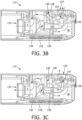
FIG. 3A is a schematic isometric view of an another apparatus for humidifying a flow of treatment gas according to one particular, non-limiting embodiment of the present invention; -
FIG. 3B is a schematic sectional view of the apparatus ofFIG. 3A taken along line II-II ofFIG. 3A shown with internal components thereof disposed in a first positioning corresponding to when a flow of treatment gas is being received by a user of the apparatus; -
FIG. 3C is a schematic sectional view of the apparatus ofFIG. 3A taken along line II-II shown with internal components thereof disposed in a second positioning corresponding to when a user of the apparatus is exhaling; and -
FIG. 3D is a top vie of the apparatus ofFIG. 3A shown with a top cover thereof removed to show internal details. - As required, detailed embodiments of the present invention are disclosed herein; however, it is to be understood that the disclosed embodiments are merely exemplary of the invention, which may be embodied in various forms. Therefore, specific structural and functional details disclosed herein are not to be interpreted as limiting, but merely as a basis for the claims and as a representative basis for teaching one skilled in the art to variously employ the present invention in virtually any appropriately detailed structure.
- As used herein, the singular form of "a", "an", and "the" include plural references unless the context clearly dictates otherwise. As used herein, the statement that two or more parts or components are "coupled" shall mean that the parts are joined or operate together either directly or indirectly, i.e., through one or more intermediate parts or components, so long as a link occurs. As used herein, "directly coupled" means that two elements are coupled directly in contact with each other. As used herein, "fixedly coupled" or "fixed" means that two components are coupled so as to move as one while maintaining a constant orientation relative to each other. As used herein, "selectively coupled" means that two elements are coupled in a manner in which the two elements may be readily uncoupled or recoupled.
- As used herein, the word "unitary" means a component is created as a single piece or unit. That is, a component that includes pieces that are created separately and then coupled together as a unit is not a "unitary" component or body. As used herein, the statement that two or more parts or components "engage" one another shall mean that the parts exert a force against one another either directly or through one or more intermediate parts or components. As used herein, the term "number" shall mean one or an integer greater than one (i.e., a plurality).
- Directional phrases used herein, such as, for example and without limitation, top, bottom, left, right, upper, lower, front, back, and derivatives thereof, relate to the orientation of the elements shown in the drawings and are not limiting upon the claims unless expressly recited therein.
-
FIG. 1 is a schematic diagram of an airwaypressure support system 2 according to one particular, non-limiting embodiment in which the present invention in its various embodiments may be implemented.Pressure support system 2 includes agas flow generator 4, adelivery conduit 6, apatient interface device 8 structured to engage about an airway of the patient, and aheadgear 10 for securingpatient interface device 8 to the head of a patient (P).Gas flow generator 4 is structured to generate a flow of breathing gas to be delivered throughpatient interface device 8 to the airway of patient P. The flow of breathing gas may be heated and/or humidified by ahumidifier 12 which may be: provided in acommon housing 14 with gas flow generator 4 (such as shown in dashed line inFIG. 1 ); provided in aseparate housing 18 which is selectively coupleable to ahousing 20 ofgas flow generator 4; or provided inhousing 18 which is separate from, and spaced a distance from,housing 20 ofgas flow generator 4. In other words,housings single housing 14, as two separate units which may be selectively coupled and uncoupled with each other, or as two separate units which are spaced apart and coupled generally only via a suitable conduit. -
Gas flow generator 4 may include, without limitation, ventilators, constant pressure support devices (such as a continuous positive airway pressure device, or CPAP device), variable pressure devices (e.g., BiPAP®, Bi-Flex®, or C-Flex™ devices manufactured and distributed by Philips Respironics of Murrysville, Pennsylvania), and auto-titration pressure support devices.Delivery conduit 6 is structured to communicate the flow of breathing gas fromgas flow generator 4 topatient interface device 8.Delivery conduit 6 andpatient interface device 8 are often collectively referred to as a patient circuit. - A BiPAP® device is a bi-level device in which the pressure provided to the patient varies with the patient's respiratory cycle, so that a higher pressure is delivered during inspiration than during expiration. An auto-titration pressure support system is a system in which the pressure varies with the condition of the patient, such as whether the patient is snoring or experiencing an apnea or hypopnea. The present invention contemplates that
gas flow generator 4 is any conventional system for delivering a flow of gas to an airway of a patient or for elevating a pressure of gas at an airway of the patient, including the pressure support systems summarized above and non-invasive ventilation systems. Although described herein in example embodiments wherein a pressurized flow of gas is utilized, it is to be appreciated that embodiments of the invention as described herein could also be readily employed in other generally non-pressurized applications (e.g., without limitation, in high flow therapy applications). - In the exemplary embodiment shown in
FIG. 1 ,patient interface device 8 includes apatient sealing assembly 16, which in the illustrated embodiment is a full face mask. It is to be appreciated, however, that other types of patient sealing assemblies, such as, without limitation, a nasal/oral mask, a nasal cushion, or any other arrangements which facilitate the delivery of the flow of breathing gas to the airway of a patient may be substituted forpatient sealing assembly 16 while remaining within the scope of the present invention. It is also to be appreciated thatheadgear 10 is provided solely for exemplary purposes and that any suitable headgear arrangement may be employed without varying from the scope of the present invention. - Referring to
FIGS. 2A-2C ,humidifier 12 includes: aninlet 22 which is structured to receive a flow of treatment gas (shown by arrows F and the associated broken line inFIG. 2B ) produced bygas flow generator 4; anoutlet 24 which is structured to convey the flow of treatment gas F to the patient; and acompartment 26 which is structured to house a volume of water W therein for humidifying the flow of treatment gas F passing throughhousing 18 andcompartment 26 thereof frominlet 22 tooutlet 24. In the example illustrated inFIGS 2B and 2C , abaffle 28 which extends generally downward intocompartment 26 from a top wall thereof is provided to encourage interaction of the flow of treatment gas F with the volume of water W. -
Humidifier 12 further includes aprimary valve 30 disposed betweeninlet 22 andcompartment 26.Primary valve 30 is a one-way valve which is moveable between an open position (FIG. 2B ), in whichprimary valve 30 is structured to permit passage of the flow of treatment gas F frominlet 22 tocompartment 26, and a closed position (FIG. 2C ) in whichprimary valve 30 is structured to prevent passage of a fluid or fluids (e.g., air, water, etc.) fromcompartment 26 toinlet 22.Primary valve 30 is normally disposed in a closed position except for when adequate pressure is acting thereon to openprimary valve 30. In one example embodiment of the present invention,primary valve 30 is a flapper valve which is structured to be disposed in an open position when a flow of treatment gas F is provided throughhumidifier 12 to a patient in the pressure range of 4 cmH2O to 25 cmH2O at a flow rate of 0 - 100 LPM. Conversely, in such example embodiment,primary valve 30 is structured to be disposed in a closed position when the aforementioned flow rate of the aforementioned flow of treatment gas F drops to a flowrate in the range of 0 to -80 LPM, such as when a patient receiving the treatment exhales exhalation gases, such as shown by arrows E (and the associated broken line) inFIG. 2C and described further below. - Continuing to refer to
FIGS. 2B and 2C ,humidifier 12 further includes asecondary valve 40 disposed betweencompartment 26 andinlet 22.Secondary valve 40 is a one-way valve which is moveable between an open position (FIG. 2C ), in whichsecondary valve 40 is structured to permit passage of a fluid, such as exhalation gases E fromcompartment 26 toinlet 22, and a closed position (FIG. 2B ) in whichsecondary valve 40 is structured to prevent passage of a fluid or fluids, such as flow of treatment gas F, frominlet 22 tocompartment 26.Secondary valve 40 is normally disposed in a closed position except for when adequate pressure is acting thereon to opensecondary valve 40. In one example embodiment of the present invention,secondary valve 40 is a duckbill valve which is structured to be disposed in an open position whenprimary valve 30 is closed and the pressure incompartment 26 is greater than the pressure ininlet 22. -
Secondary valve 40 is needed to relieve expiratory flow during the exhalation cycle of CPAP therapy.Secondary valve 40 is needed in order to have effective water ingress protection (i.e., to keep water from exitinghumidifier 12 via inlet 22). The placement ofsecondary valve 40 is critical to the function of the two valve system. According to the invention thesecondary valve 40 is placed betweenprimary valve 30 andinlet 22 ofhumidifier 12. Preferably,secondary valve 40 is also placed in an orientation where it is difficult to submerge in water when the device is rotated 360 degrees so that the system can be properly vented as previously described. - From the foregoing description of
humidifier 12, it is thus to be appreciated that during a CPAP treatment,primary valve 30 is generally disposed in an open position with the flow of treatment gas F passing intohumidifier 12 viainlet 22, passing throughprimary valve 30, being directed generally toward water W bybaffle 28, then exiting fromchamber 26 andhumidifier 12 viaoutlet 24, and then passing onward to the patient. However, when a patient is exhaling, the resulting pressure/flow causesprimary valve 30 to return to a closed position andsecondary valve 40 to open, thus allowing the flow of exhalation gasesE entering humidifier 12 viaoutlet 24 to pass throughhumidifier 12 and exit viainlet 22. When a CPAP treatment is not occurring, bothprimary valve 30 andsecondary valve 40 are disposed in closed positions, thus preventing any water W from exitingchamber 26, and thus preventing any water from exitinginlet 22. - Referring now to
FIGS. 3A-3D , ahumidifier 112 in accordance with another example embodiment of the invention which may be employed insystem 2 ofFIG. 1 is shown.Humidifier 112 includes: aninlet 122 which is structured to receive a flow of treatment gas (shown by arrows F inFIG. 3B ) produced by a gas flow generator, such agas flow generator 4 previously discussed; anoutlet 124 which is structured to convey the flow of treatment gas F; and acompartment 126 which is structured to house a volume of water W therein for humidifying the flow of treatment gas F passing throughhousing 118 andcompartment 126 thereof frominlet 122 tooutlet 124. In the example illustrated inFIGS 3B-3D , abaffle 128 which extends generally downward intocompartment 126 from a top wall thereof is provided to encourage interaction of the flow of treatment gas F with the volume of water W. -
Humidifier 112 further includes aprimary valve 130 disposed betweeninlet 122 andcompartment 126.Primary valve 130 is a one-way valve which is moveable between an open position (FIG. 3B ), in whichprimary valve 130 is structured to permit passage of the flow of treatment gas F frominlet 122 tocompartment 126, and a closed position (FIG. 3C ) in whichprimary valve 130 is structured to prevent passage of a fluid or fluids (e.g., air, water, etc.) fromcompartment 126 toinlet 122. In one example embodiment of the present invention,primary valve 130 is a flapper valve which is structured to be disposed in an open position when a flow of treatment gas F is provided throughhumidifier 112 to a patient in the pressure range of 4 cmH2O to 25 cmH2O at a flow rate of 0 - 100 LPM. Conversely, in such example embodiment,primary valve 130 is structured to be disposed in a closed position when the aforementioned flow rate of the aforementioned flow of treatment gas F drops to a flowrate in the range of 0 to -80 LPM, such as when a patient receiving the treatment exhales exhalation gases, such as shown by arrows E inFIG. 3C and described further below. - Continuing to refer to
FIGS. 3B and 3C ,humidifier 112 further includes asecondary valve 140 disposed betweencompartment 126 andinlet 122.Secondary valve 140 is a one-way valve which is moveable between an open position (FIG. 3C ), in whichsecondary valve 140 is structured to permit passage of a fluid, such as exhalation gases E fromcompartment 126 toinlet 122, and a closed position (FIG. 3B ) in whichsecondary valve 140 is structured to prevent passage of a fluid or fluids, such as flow of treatment gas F, frominlet 122 tocompartment 126. - In one example embodiment of the present invention,
secondary valve 140 is a flapper valve which is structured to be disposed in a closed position whenprimary valve 130 is open, and structured to be disposed in an open position when the pressure incompartment 126 is greater than the pressure ininlet 122.Secondary valve 140 is needed to prevent therapy flow in the positive direction from traveling throughbypass tube 150 and outoutlet 124, thus bypassing the humidifier and reducing humidification output. - In order to reduce and/or eliminate loss of water W from
compartment 126 throughsecondary valve 140 during exhalation,humidifier 112 further includes abypass tube 150 which defines anelongated passage 152 therein.Elongated passage 152 extends betweensecondary valve 140 and adistal opening 154 ofbypass tube 150 disposed at or aboutoutlet 124. In the example embodiment illustrated inFIGS. 3B-3D ,distal opening 154 is generally aligned (i.e., disposed along a common central axis) withoutlet 124. Such positioning ofdistal opening 154 nearinlet outlet 124 generally eliminates interaction between exhalation gases E and the water W insidechamber 126 as exhalation gases E are not generally exposed to the water W therein. - From the foregoing description of
humidifier 112, it is thus to be appreciated that during a CPAP treatment,primary valve 130 is generally disposed in an open position with the flow of treatment gas F passing intohumidifier 112 viainlet 122, passing throughprimary valve 130, being directed generally toward water W by baffle 128 (and around bypass tube 150), then exiting fromchamber 126 andhumidifier 112 upward away fromdistal opening 154 viaoutlet 124, and passing onward to the patient. However, when a patient is exhaling, the resulting pressure/flow causesprimary valve 130 to return to a closed position andsecondary valve 140 to open as the flow of exhalation gasesE entering humidifier 112 viaoutlet 124 immediately enterdistal opening 154 ofbypass tube 150, pass throughbypass tube 150 andsecondary valve 140, andexit humidifier 112 viainlet 22. When a CPAP treatment is not occurring, bothprimary valve 130 andsecondary valve 140 are disposed in closed positions, thus preventing any water W from exitingchamber 126, and thus preventing any water from exitinginlet 122. - From the foregoing examples it is to be appreciated that embodiments of the present invention overcome disadvantages or problems of the prior arrangements by eliminating the need for a large volume tank which was previously needed in order to achieve effective volumetric water ingress protection. By eliminating the need for a large volume tank, more design flexibility is achieved and smaller lower profile systems can be used while still maintaining 360-degree water ingress protection.
- Although the invention has been described in detail for the purpose of illustration based on what is currently considered to be the most practical and preferred embodiments, it is to be understood that such detail is solely for that purpose and that the invention is not limited to the disclosed embodiments, but, on the contrary, is intended to cover modifications and equivalent arrangements that are within the scope of the appended claims. For example, it is to be understood that the present invention contemplates that, to the extent possible, one or more features of any embodiment can be combined with one or more features of any other embodiment.
- In the claims, any reference signs placed between parentheses shall not be construed as limiting the claim. The word "comprising" or "including" does not exclude the presence of elements or steps other than those listed in a claim. In a device claim enumerating several means, several of these means may be embodied by one and the same item of hardware. The word "a" or "an" preceding an element does not exclude the presence of a plurality of such elements. In any device claim enumerating several means, several of these means may be embodied by one and the same item of hardware. The mere fact that certain elements are recited in mutually different dependent claims does not indicate that these elements cannot be used in combination.
Claims (11)
- An apparatus (12, 112) for use in humidifying a flow of treatment gas (F) for providing to a user (P), the apparatus comprising:a housing (18, 118);an inlet (22, 122) structured to receive the flow of treatment gas from a gas flow generator (4);an outlet (24, 124) structured to convey the flow of treatment gas to a patient interface device (8);a compartment (26, 126) defined in the housing, the compartment being structured to hold a volume of water (W) therein;a primary valve (30, 130) disposed between the inlet and the compartment, the primary valve being structured to permit passage of the flow of treatment gas from the inlet to the compartment and to prevent passage of a fluid from the compartment to the inlet; anda secondary valve (40, 140) disposed between the compartment and the inlet, the secondary valve being structured to permit passage of a fluid from the compartment to the inlet and to prevent passage of the flow of treatment gas from the inlet to the compartment,characterized in that the secondary valve (40, 140) is placed between the primary valve (30, 130) and the inlet (22. 122) of the apparatus (12, 112) and wherein the apparatus further comprises an elongated passage extending between the secondary valve and a distal end disposed at or about the outlet, wherein the elongated passage is structured to convey the fluid from the outlet to the secondary valve without exposing the fluid to the volume of water.
- The apparatus of claim 1, wherein the primary valve comprises a flapper valve.
- The apparatus of claim 1 or 2, wherein the secondary valve comprises a duckbill valve or a flapper valve.
- A device for use in providing a humidified flow of a treatment gas (F) to the airway of a user (P), the device comprising:a housing (14);a flow generating device (4) disposed in the housing, the flow generating device structured to produce the flow of the treatment gas; andan apparatus (12, 112) disposed in the housing for humidifying the flow of the treatment gas, the apparatus comprising:an inlet (22, 122) structured to receive the flow of treatment gas from the flow generating device;an outlet (24, 124) structured to convey the flow of treatment gas;a compartment (26, 126) defined in the housing, the compartment being structured to hold a volume of water (W) therein;a primary valve (30, 130) disposed between the inlet and the compartment, the primary valve being structured to permit passage of the flow of treatment gas from the inlet to the compartment and to prevent passage of a fluid from the compartment to the inlet; anda secondary valve (40, 140) disposed between the compartment and the inlet, the secondary valve being structured to permit passage of a fluid from the compartment to the inlet and to prevent passage of the flow of treatment gas from the inlet to the compartmentcharacterized in that the secondary valve (40, 140) is placed between the primary valve (30, 130) and the inlet (22. 122) of the apparatus (12, 112) wherein the apparatus further comprises an elongated passage extending between the secondary valve and a distal end disposed at or about the outlet, wherein the elongated passage is structured to convey the fluid from the outlet to the secondary valve without exposing the fluid to the volume of water.
- The device of claim 4, wherein the housing (14) comprises a first housing (20) and a second housing (18) selectively coupled to the first housing;wherein the flow generating device is disposed in the first housing;and wherein the apparatus is disposed in the second housing.
- The device of claim 4 or 5, wherein the primary valve comprises a flapper valve.
- The device of any of claims 4-6, wherein the secondary valve comprises a duckbill valve or a flapper valve.
- A system (2) for providing a humidified flow of a treatment gas to the airway of a user, the system comprising:a device according to claim 4, and a delivery conduit (6) having a first end coupled to the outlet of the apparatus and an opposite second end; anda patient interface device (8) coupled to the second end of the conduit, wherein the conduit is structured to convey the flow of treatment from the outlet to the patient interface device.
- The system of claim 8, wherein the housing (14) comprises a first housing (20) and a second housing (18) selectively coupled to the first housing;wherein the flow generating device is disposed in the first housing;and wherein the apparatus is disposed in the second housing.
- The system of claim 8 or 9, wherein the primary valve comprises a flapper valve.
- The system of any of claims 8-10, wherein the secondary valve comprises a duckbill valve or a flapper valve.
Applications Claiming Priority (2)
| Application Number | Priority Date | Filing Date | Title |
|---|---|---|---|
| US201862738306P | 2018-09-28 | 2018-09-28 | |
| PCT/EP2019/075777 WO2020064784A1 (en) | 2018-09-28 | 2019-09-25 | Humidifier with ingress protection for use in cpap therapy |
Publications (2)
| Publication Number | Publication Date |
|---|---|
| EP3856313A1 EP3856313A1 (en) | 2021-08-04 |
| EP3856313B1 true EP3856313B1 (en) | 2023-05-24 |
Family
ID=68109287
Family Applications (1)
| Application Number | Title | Priority Date | Filing Date |
|---|---|---|---|
| EP19780188.9A Active EP3856313B1 (en) | 2018-09-28 | 2019-09-25 | Humidifier with ingress protection for use in cpap therapy |
Country Status (5)
| Country | Link |
|---|---|
| US (1) | US11623063B2 (en) |
| EP (1) | EP3856313B1 (en) |
| JP (1) | JP7471282B2 (en) |
| CN (1) | CN112867526B (en) |
| WO (1) | WO2020064784A1 (en) |
Families Citing this family (3)
| Publication number | Priority date | Publication date | Assignee | Title |
|---|---|---|---|---|
| JP7347657B2 (en) * | 2020-04-08 | 2023-09-20 | 株式会社村田製作所 | humidifier |
| GB2600671A (en) * | 2020-09-01 | 2022-05-11 | Seager Simon | A condenser device for a respiratory apparatus |
| JP2023551779A (en) * | 2020-10-29 | 2023-12-13 | レスメド・プロプライエタリー・リミテッド | Assembly for diverting liquid from a breathing device |
Family Cites Families (14)
| Publication number | Priority date | Publication date | Assignee | Title |
|---|---|---|---|---|
| CA2370995C (en) * | 2001-09-13 | 2010-08-17 | Fisher & Paykel Healthcare Limited | Breathing assistance apparatus |
| US7616871B2 (en) * | 2003-08-20 | 2009-11-10 | Fisher & Paykel Healthcare Limited | Water chamber for humidifier |
| US8028697B2 (en) * | 2005-04-28 | 2011-10-04 | Trudell Medical International | Ventilator circuit and method for the use thereof |
| US8997740B2 (en) * | 2005-09-27 | 2015-04-07 | Ric Investments, Llc | Humidifier with back-flow prevention valve |
| CN200948893Y (en) * | 2006-07-24 | 2007-09-19 | 黄芳 | Multiple-chamber drinking bottle |
| CN103079621B (en) * | 2010-06-30 | 2015-09-16 | 圣米高医院 | For the method and system that the ventilation synchronous with patient by tracheal strips through-flow is auxiliary |
| EP2608836B1 (en) * | 2010-08-27 | 2018-03-28 | Koninklijke Philips N.V. | Portable humidification system and adaptor therefore |
| CN103180006B (en) * | 2010-09-06 | 2016-08-10 | 瑞思迈有限公司 | For preventing the method and apparatus condensing water |
| CN103167891B (en) * | 2010-10-21 | 2016-04-20 | 皇家飞利浦电子股份有限公司 | Humidifier bypass valve |
| NZ628024A (en) * | 2010-11-15 | 2016-02-26 | ResMed Humidification Technologies GmbH | Methods and devices in the field of treatment with medical gases |
| CN104411355B (en) * | 2012-05-02 | 2017-11-03 | 费雪派克医疗保健有限公司 | Respiratory humidification device communication system and method |
| RU2677056C2 (en) * | 2013-06-28 | 2019-01-15 | Конинклейке Филипс Н.В. | Humidifier assembly and method of providing moisture to supplied gas in a pressure support system |
| CN204319448U (en) * | 2014-12-14 | 2015-05-13 | 刘绍妍 | A kind of breathing apparatus for cardiovascular department |
| US10773049B2 (en) * | 2016-06-21 | 2020-09-15 | Ventec Life Systems, Inc. | Cough-assist systems with humidifier bypass |
-
2019
- 2019-09-25 JP JP2021516802A patent/JP7471282B2/en active Active
- 2019-09-25 CN CN201980068789.5A patent/CN112867526B/en active Active
- 2019-09-25 WO PCT/EP2019/075777 patent/WO2020064784A1/en unknown
- 2019-09-25 EP EP19780188.9A patent/EP3856313B1/en active Active
- 2019-09-25 US US16/582,201 patent/US11623063B2/en active Active
Also Published As
| Publication number | Publication date |
|---|---|
| WO2020064784A1 (en) | 2020-04-02 |
| JP2022502156A (en) | 2022-01-11 |
| EP3856313A1 (en) | 2021-08-04 |
| US20200101259A1 (en) | 2020-04-02 |
| US11623063B2 (en) | 2023-04-11 |
| CN112867526A (en) | 2021-05-28 |
| JP7471282B2 (en) | 2024-04-19 |
| CN112867526B (en) | 2024-10-18 |
Similar Documents
| Publication | Publication Date | Title |
|---|---|---|
| US10737052B2 (en) | Fluid coupling member including valve member | |
| US11484682B2 (en) | Humidifier with ingress protection for use in CPAP therapy | |
| JP6327752B2 (en) | Anti-suffocation valve assembly | |
| EP3013401B1 (en) | Humidifier assembly and method of providing moisture to supplied gas in a pressure support system. | |
| EP3856313B1 (en) | Humidifier with ingress protection for use in cpap therapy | |
| US20220288338A1 (en) | Customizable mask and method of sizing | |
| EP3600510B1 (en) | Moisture wicking conduit and system cross-reference to related applications | |
| US20150059758A1 (en) | Selectable exhaust port assembly | |
| US12097326B2 (en) | Patient interface having a restrictor element for varying flow resistance through an exhalation port thereof | |
| EP3313493B1 (en) | Collapsible humidifier | |
| US20210260326A1 (en) | Nasal portion and patient interface device including same cross-reference to related applications | |
| US11389606B2 (en) | Compact fluid moving assembly and device employing same |
Legal Events
| Date | Code | Title | Description |
|---|---|---|---|
| STAA | Information on the status of an ep patent application or granted ep patent |
Free format text: STATUS: UNKNOWN |
|
| STAA | Information on the status of an ep patent application or granted ep patent |
Free format text: STATUS: THE INTERNATIONAL PUBLICATION HAS BEEN MADE |
|
| PUAI | Public reference made under article 153(3) epc to a published international application that has entered the european phase |
Free format text: ORIGINAL CODE: 0009012 |
|
| STAA | Information on the status of an ep patent application or granted ep patent |
Free format text: STATUS: REQUEST FOR EXAMINATION WAS MADE |
|
| 17P | Request for examination filed |
Effective date: 20210428 |
|
| AK | Designated contracting states |
Kind code of ref document: A1 Designated state(s): AL AT BE BG CH CY CZ DE DK EE ES FI FR GB GR HR HU IE IS IT LI LT LU LV MC MK MT NL NO PL PT RO RS SE SI SK SM TR |
|
| DAV | Request for validation of the european patent (deleted) | ||
| DAX | Request for extension of the european patent (deleted) | ||
| GRAP | Despatch of communication of intention to grant a patent |
Free format text: ORIGINAL CODE: EPIDOSNIGR1 |
|
| STAA | Information on the status of an ep patent application or granted ep patent |
Free format text: STATUS: GRANT OF PATENT IS INTENDED |
|
| INTG | Intention to grant announced |
Effective date: 20221216 |
|
| GRAS | Grant fee paid |
Free format text: ORIGINAL CODE: EPIDOSNIGR3 |
|
| GRAA | (expected) grant |
Free format text: ORIGINAL CODE: 0009210 |
|
| STAA | Information on the status of an ep patent application or granted ep patent |
Free format text: STATUS: THE PATENT HAS BEEN GRANTED |
|
| AK | Designated contracting states |
Kind code of ref document: B1 Designated state(s): AL AT BE BG CH CY CZ DE DK EE ES FI FR GB GR HR HU IE IS IT LI LT LU LV MC MK MT NL NO PL PT RO RS SE SI SK SM TR |
|
| REG | Reference to a national code |
Ref country code: GB Ref legal event code: FG4D |
|
| REG | Reference to a national code |
Ref country code: CH Ref legal event code: EP |
|
| REG | Reference to a national code |
Ref country code: DE Ref legal event code: R096 Ref document number: 602019029301 Country of ref document: DE |
|
| REG | Reference to a national code |
Ref country code: AT Ref legal event code: REF Ref document number: 1569157 Country of ref document: AT Kind code of ref document: T Effective date: 20230615 |
|
| REG | Reference to a national code |
Ref country code: IE Ref legal event code: FG4D |
|
| REG | Reference to a national code |
Ref country code: LT Ref legal event code: MG9D |
|
| REG | Reference to a national code |
Ref country code: NL Ref legal event code: MP Effective date: 20230524 |
|
| REG | Reference to a national code |
Ref country code: AT Ref legal event code: MK05 Ref document number: 1569157 Country of ref document: AT Kind code of ref document: T Effective date: 20230524 |
|
| PG25 | Lapsed in a contracting state [announced via postgrant information from national office to epo] |
Ref country code: SE Free format text: LAPSE BECAUSE OF FAILURE TO SUBMIT A TRANSLATION OF THE DESCRIPTION OR TO PAY THE FEE WITHIN THE PRESCRIBED TIME-LIMIT Effective date: 20230524 Ref country code: PT Free format text: LAPSE BECAUSE OF FAILURE TO SUBMIT A TRANSLATION OF THE DESCRIPTION OR TO PAY THE FEE WITHIN THE PRESCRIBED TIME-LIMIT Effective date: 20230925 Ref country code: NO Free format text: LAPSE BECAUSE OF FAILURE TO SUBMIT A TRANSLATION OF THE DESCRIPTION OR TO PAY THE FEE WITHIN THE PRESCRIBED TIME-LIMIT Effective date: 20230824 Ref country code: NL Free format text: LAPSE BECAUSE OF FAILURE TO SUBMIT A TRANSLATION OF THE DESCRIPTION OR TO PAY THE FEE WITHIN THE PRESCRIBED TIME-LIMIT Effective date: 20230524 Ref country code: ES Free format text: LAPSE BECAUSE OF FAILURE TO SUBMIT A TRANSLATION OF THE DESCRIPTION OR TO PAY THE FEE WITHIN THE PRESCRIBED TIME-LIMIT Effective date: 20230524 Ref country code: AT Free format text: LAPSE BECAUSE OF FAILURE TO SUBMIT A TRANSLATION OF THE DESCRIPTION OR TO PAY THE FEE WITHIN THE PRESCRIBED TIME-LIMIT Effective date: 20230524 |
|
| PG25 | Lapsed in a contracting state [announced via postgrant information from national office to epo] |
Ref country code: RS Free format text: LAPSE BECAUSE OF FAILURE TO SUBMIT A TRANSLATION OF THE DESCRIPTION OR TO PAY THE FEE WITHIN THE PRESCRIBED TIME-LIMIT Effective date: 20230524 Ref country code: PL Free format text: LAPSE BECAUSE OF FAILURE TO SUBMIT A TRANSLATION OF THE DESCRIPTION OR TO PAY THE FEE WITHIN THE PRESCRIBED TIME-LIMIT Effective date: 20230524 Ref country code: LV Free format text: LAPSE BECAUSE OF FAILURE TO SUBMIT A TRANSLATION OF THE DESCRIPTION OR TO PAY THE FEE WITHIN THE PRESCRIBED TIME-LIMIT Effective date: 20230524 Ref country code: LT Free format text: LAPSE BECAUSE OF FAILURE TO SUBMIT A TRANSLATION OF THE DESCRIPTION OR TO PAY THE FEE WITHIN THE PRESCRIBED TIME-LIMIT Effective date: 20230524 Ref country code: IS Free format text: LAPSE BECAUSE OF FAILURE TO SUBMIT A TRANSLATION OF THE DESCRIPTION OR TO PAY THE FEE WITHIN THE PRESCRIBED TIME-LIMIT Effective date: 20230924 Ref country code: HR Free format text: LAPSE BECAUSE OF FAILURE TO SUBMIT A TRANSLATION OF THE DESCRIPTION OR TO PAY THE FEE WITHIN THE PRESCRIBED TIME-LIMIT Effective date: 20230524 Ref country code: GR Free format text: LAPSE BECAUSE OF FAILURE TO SUBMIT A TRANSLATION OF THE DESCRIPTION OR TO PAY THE FEE WITHIN THE PRESCRIBED TIME-LIMIT Effective date: 20230825 |
|
| PG25 | Lapsed in a contracting state [announced via postgrant information from national office to epo] |
Ref country code: FI Free format text: LAPSE BECAUSE OF FAILURE TO SUBMIT A TRANSLATION OF THE DESCRIPTION OR TO PAY THE FEE WITHIN THE PRESCRIBED TIME-LIMIT Effective date: 20230524 |
|
| PG25 | Lapsed in a contracting state [announced via postgrant information from national office to epo] |
Ref country code: SK Free format text: LAPSE BECAUSE OF FAILURE TO SUBMIT A TRANSLATION OF THE DESCRIPTION OR TO PAY THE FEE WITHIN THE PRESCRIBED TIME-LIMIT Effective date: 20230524 |
|
| PG25 | Lapsed in a contracting state [announced via postgrant information from national office to epo] |
Ref country code: SM Free format text: LAPSE BECAUSE OF FAILURE TO SUBMIT A TRANSLATION OF THE DESCRIPTION OR TO PAY THE FEE WITHIN THE PRESCRIBED TIME-LIMIT Effective date: 20230524 Ref country code: SK Free format text: LAPSE BECAUSE OF FAILURE TO SUBMIT A TRANSLATION OF THE DESCRIPTION OR TO PAY THE FEE WITHIN THE PRESCRIBED TIME-LIMIT Effective date: 20230524 Ref country code: RO Free format text: LAPSE BECAUSE OF FAILURE TO SUBMIT A TRANSLATION OF THE DESCRIPTION OR TO PAY THE FEE WITHIN THE PRESCRIBED TIME-LIMIT Effective date: 20230524 Ref country code: EE Free format text: LAPSE BECAUSE OF FAILURE TO SUBMIT A TRANSLATION OF THE DESCRIPTION OR TO PAY THE FEE WITHIN THE PRESCRIBED TIME-LIMIT Effective date: 20230524 Ref country code: DK Free format text: LAPSE BECAUSE OF FAILURE TO SUBMIT A TRANSLATION OF THE DESCRIPTION OR TO PAY THE FEE WITHIN THE PRESCRIBED TIME-LIMIT Effective date: 20230524 Ref country code: CZ Free format text: LAPSE BECAUSE OF FAILURE TO SUBMIT A TRANSLATION OF THE DESCRIPTION OR TO PAY THE FEE WITHIN THE PRESCRIBED TIME-LIMIT Effective date: 20230524 |
|
| REG | Reference to a national code |
Ref country code: DE Ref legal event code: R097 Ref document number: 602019029301 Country of ref document: DE |
|
| PLBE | No opposition filed within time limit |
Free format text: ORIGINAL CODE: 0009261 |
|
| STAA | Information on the status of an ep patent application or granted ep patent |
Free format text: STATUS: NO OPPOSITION FILED WITHIN TIME LIMIT |
|
| REG | Reference to a national code |
Ref country code: CH Ref legal event code: PL |
|
| 26N | No opposition filed |
Effective date: 20240227 |
|
| PG25 | Lapsed in a contracting state [announced via postgrant information from national office to epo] |
Ref country code: SI Free format text: LAPSE BECAUSE OF FAILURE TO SUBMIT A TRANSLATION OF THE DESCRIPTION OR TO PAY THE FEE WITHIN THE PRESCRIBED TIME-LIMIT Effective date: 20230524 |
|
| PG25 | Lapsed in a contracting state [announced via postgrant information from national office to epo] |
Ref country code: LU Free format text: LAPSE BECAUSE OF NON-PAYMENT OF DUE FEES Effective date: 20230925 |
|
| REG | Reference to a national code |
Ref country code: BE Ref legal event code: MM Effective date: 20230930 |
|
| PG25 | Lapsed in a contracting state [announced via postgrant information from national office to epo] |
Ref country code: SI Free format text: LAPSE BECAUSE OF FAILURE TO SUBMIT A TRANSLATION OF THE DESCRIPTION OR TO PAY THE FEE WITHIN THE PRESCRIBED TIME-LIMIT Effective date: 20230524 Ref country code: LU Free format text: LAPSE BECAUSE OF NON-PAYMENT OF DUE FEES Effective date: 20230925 Ref country code: IT Free format text: LAPSE BECAUSE OF FAILURE TO SUBMIT A TRANSLATION OF THE DESCRIPTION OR TO PAY THE FEE WITHIN THE PRESCRIBED TIME-LIMIT Effective date: 20230524 Ref country code: MC Free format text: LAPSE BECAUSE OF FAILURE TO SUBMIT A TRANSLATION OF THE DESCRIPTION OR TO PAY THE FEE WITHIN THE PRESCRIBED TIME-LIMIT Effective date: 20230524 |
|
| REG | Reference to a national code |
Ref country code: IE Ref legal event code: MM4A |
|
| PG25 | Lapsed in a contracting state [announced via postgrant information from national office to epo] |
Ref country code: IE Free format text: LAPSE BECAUSE OF NON-PAYMENT OF DUE FEES Effective date: 20230925 |
|
| PG25 | Lapsed in a contracting state [announced via postgrant information from national office to epo] |
Ref country code: CH Free format text: LAPSE BECAUSE OF NON-PAYMENT OF DUE FEES Effective date: 20230930 |
|
| PG25 | Lapsed in a contracting state [announced via postgrant information from national office to epo] |
Ref country code: IE Free format text: LAPSE BECAUSE OF NON-PAYMENT OF DUE FEES Effective date: 20230925 Ref country code: CH Free format text: LAPSE BECAUSE OF NON-PAYMENT OF DUE FEES Effective date: 20230930 |
|
| PG25 | Lapsed in a contracting state [announced via postgrant information from national office to epo] |
Ref country code: BE Free format text: LAPSE BECAUSE OF NON-PAYMENT OF DUE FEES Effective date: 20230930 |
|
| PGFP | Annual fee paid to national office [announced via postgrant information from national office to epo] |
Ref country code: DE Payment date: 20240926 Year of fee payment: 6 |
|
| PGFP | Annual fee paid to national office [announced via postgrant information from national office to epo] |
Ref country code: GB Payment date: 20240924 Year of fee payment: 6 |
|
| PGFP | Annual fee paid to national office [announced via postgrant information from national office to epo] |
Ref country code: FR Payment date: 20240925 Year of fee payment: 6 |