EP3599340B1 - Dispositif de forage - Google Patents
Dispositif de forage Download PDFInfo
- Publication number
- EP3599340B1 EP3599340B1 EP18185397.9A EP18185397A EP3599340B1 EP 3599340 B1 EP3599340 B1 EP 3599340B1 EP 18185397 A EP18185397 A EP 18185397A EP 3599340 B1 EP3599340 B1 EP 3599340B1
- Authority
- EP
- European Patent Office
- Prior art keywords
- rod
- guide
- pair
- drilling
- drill
- Prior art date
- Legal status (The legal status is an assumption and is not a legal conclusion. Google has not performed a legal analysis and makes no representation as to the accuracy of the status listed.)
- Active
Links
- 238000005553 drilling Methods 0.000 title claims description 75
- 230000008878 coupling Effects 0.000 claims description 5
- 238000010168 coupling process Methods 0.000 claims description 5
- 238000005859 coupling reaction Methods 0.000 claims description 5
- 125000006850 spacer group Chemical group 0.000 claims description 5
- 230000032258 transport Effects 0.000 description 54
- 230000002950 deficient Effects 0.000 description 3
- 239000012530 fluid Substances 0.000 description 3
- 230000007246 mechanism Effects 0.000 description 3
- 238000010276 construction Methods 0.000 description 2
- 239000011435 rock Substances 0.000 description 2
- 238000013459 approach Methods 0.000 description 1
- 230000006835 compression Effects 0.000 description 1
- 238000007906 compression Methods 0.000 description 1
- 238000011161 development Methods 0.000 description 1
- 230000018109 developmental process Effects 0.000 description 1
- 230000002349 favourable effect Effects 0.000 description 1
- 238000011010 flushing procedure Methods 0.000 description 1
- 238000003780 insertion Methods 0.000 description 1
- 230000037431 insertion Effects 0.000 description 1
- 238000009434 installation Methods 0.000 description 1
- 238000005259 measurement Methods 0.000 description 1
- 238000000034 method Methods 0.000 description 1
- 238000012986 modification Methods 0.000 description 1
- 230000004048 modification Effects 0.000 description 1
- 238000007639 printing Methods 0.000 description 1
- 230000008569 process Effects 0.000 description 1
- 238000011084 recovery Methods 0.000 description 1
- 230000000630 rising effect Effects 0.000 description 1
- 230000008685 targeting Effects 0.000 description 1
- 230000007704 transition Effects 0.000 description 1
Images


Classifications
-
- E—FIXED CONSTRUCTIONS
- E21—EARTH OR ROCK DRILLING; MINING
- E21B—EARTH OR ROCK DRILLING; OBTAINING OIL, GAS, WATER, SOLUBLE OR MELTABLE MATERIALS OR A SLURRY OF MINERALS FROM WELLS
- E21B7/00—Special methods or apparatus for drilling
- E21B7/04—Directional drilling
-
- E—FIXED CONSTRUCTIONS
- E21—EARTH OR ROCK DRILLING; MINING
- E21B—EARTH OR ROCK DRILLING; OBTAINING OIL, GAS, WATER, SOLUBLE OR MELTABLE MATERIALS OR A SLURRY OF MINERALS FROM WELLS
- E21B19/00—Handling rods, casings, tubes or the like outside the borehole, e.g. in the derrick; Apparatus for feeding the rods or cables
- E21B19/16—Connecting or disconnecting pipe couplings or joints
-
- E—FIXED CONSTRUCTIONS
- E21—EARTH OR ROCK DRILLING; MINING
- E21B—EARTH OR ROCK DRILLING; OBTAINING OIL, GAS, WATER, SOLUBLE OR MELTABLE MATERIALS OR A SLURRY OF MINERALS FROM WELLS
- E21B7/00—Special methods or apparatus for drilling
- E21B7/04—Directional drilling
- E21B7/046—Directional drilling horizontal drilling
Definitions
- the invention is directed to a drilling device comprising a guide frame, a guide table which is mounted on the guide frame so as to be movable in a longitudinal direction of the guide frame, and a drill drive which is fastened on the guide table and which has a motor-driven clamping head for rotating a drill rod and a rod. Implementation which enables a drill rod released by the clamping head to be pulled through the drill drive.
- a drilling device for horizontal drilling comprising a drill head, a drill rod and a drive device which is designed for the rotary drive and feed drive of the drill rod.
- the drill rod has an inner rod and an outer rod, between which an annular space for guiding a flushing fluid from a rotary connection to the drill head is formed.
- the inner linkage comprises a straightening space which extends from the drive device to a terminating element on the drill head side. At least part of a targeting device for controlling the direction of the drill head is arranged in the straightening space.
- a rod positioning device which is attached to a frame and moves a drill rod from a magazine into the drilling axis in order to then connect the drill rod to a drill rod already arranged in the drilling axis.
- a Kelly bar drilling device which is driven to rotate by a drill head, the drilling device having at least one outer Kelly bar which is arranged only below the drill head and which is either one on the drill head provided rotating transition piece or is driven by the next inner Kelly bar. At least the outermost Kelly bar does not run through the drill head, so that the diameter of the drill head can be kept small and yet a great drilling depth can be achieved.
- a drilling device for creating a borehole in a ground is known, a drill rod being driven to rotate via a drive shaft of a rotary drive and being introduced into the ground in order to create the borehole.
- a fluid is supplied to the borehole through the tubular drill pipe, a standpipe being introduced into an upper region of the ground in a rotating manner by means of the rotary drive of the drill pipe.
- the standpipe surrounds the drill pipe, an annulus being formed between the drill pipe and the stand pipe.
- the standpipe is decoupled from the rotary drive and fixed in a stationary manner by means of a holding device, with the drill rod for creating the borehole being introduced through the stationary standpipe into a lower area of the floor. Fluid rising from the borehole is discharged from the borehole via the annular space and discharged in a defined manner via an ejection head with an ejection opening.
- a drilling device of the type described above is known from the prior art and is used, for example, to carry out core drilling with suitable drill rods.
- several drill rods are connected to one another and form a drill string.
- the disadvantage of this known drilling device is that replacing a defective drill head is very time-consuming, since the drill string consisting of several drill pipes can only be pulled out of the drill hole in batches for each individual drill pipe due to the limited travel of the guide table. Introducing the drill string after replacing the defective one Drilling head is also very time-consuming due to the limited travel of the guide table.
- such drilling devices can only be used to a limited extent for measuring boreholes. Because of the limited travel of the guide table and the usually too low travel speed of the guide table, the known drilling devices are hardly suitable for radar measurements, for example, since the recording speed is insufficient to obtain spatial structural information on the geology and tectonics of the rocks.
- the invention is based on the object of creating a solution which provides an improved drilling device in a structurally simple manner, with which a plurality of drill rods connected to one another to form a drill string can be quickly and continuously withdrawn from the borehole or inserted into the borehole and with which a continuous travel speed of the drill string that is suitable for measuring the rocks can be achieved.
- a rod pushing device is attached to the guide frame, which can be connected to the drill rod in a force-locking manner and the drill rod is designed to move in the longitudinal direction of the guide frame.
- the invention provides a drilling device which is characterized by a simple and inexpensive construction.
- the component according to the invention of the rod pushing device now makes it possible to insert a drill string consisting of several drill rods into a borehole or to retrieve it from a borehole within a very short time.
- the rod pushing device is an additional functional unit on the drilling device and is designed in such a way that certain functions on the drilling device, such as turning the drill string with the help of the clamping head and screwing and end screwing threaded connections of the drill rods, can still be performed and that the rod pushing device can be connected to existing drilling devices in the area of the guide frame can be adapted. Consequently, existing drilling devices can be retrofitted with the rod pushing device according to the invention.
- the frictional connection provides a sufficient coefficient of friction to transport long drill strings for very deep holes.
- the invention provides in an embodiment that the rod pushing device has at least one drive motor and at least one pair of transport rollers, of which at least one transport roller is drivingly connected to the at least one drive motor, with at least one transport roller of the at least one pair of transport rollers the other transport roller of the at least one pair of transport rollers can be moved towards or is mounted movably away from the other transport roller of the at least one pair of transport rollers, the at least one pair of transport rollers being designed to clamp or release the drill rod between them in a force-fitting manner.
- the rod pushing device has at least one pressure bracket which is designed to be movable transversely to the longitudinal direction of the guide frame and on which a transport roller of the at least one pair of transport rollers is rotatably mounted.
- the at least one pressure console can, for example, with the aid of a hydraulically operated pressure cylinder are moved transversely to the longitudinal direction of the guide frame.
- the linkage pushing device has at least one pair of guide rollers, at least one guide roller of the at least one pair of guide rollers being movable towards the other guide roller of the at least one pair of guide rollers or from the other guide roller of the at least one Pair of guide rollers is mounted movably away, wherein the at least one pair of guide rollers is designed to guide the drill rod between them.
- the guide rollers consequently support precise guidance of a drill string transported by the rod pushing device and align the drill string in the direction of the borehole and the drilling axis so that no unnecessary energy has to be applied to transport the drill string.
- the rod pushing device has at least one pressure piece which is designed to be movable transversely to the longitudinal direction of the guide frame and on which a guide roller of the at least one pair of guide rollers is rotatably mounted.
- the invention provides in a further embodiment that the rod pushing device has at least one mechanical pressure element which exerts a pressure force that urges the at least one pressure piece transversely to the longitudinal direction of the guide frame and moves the guide rollers towards one another. It is particularly favorable in terms of construction if the pressure element is designed as a spring element.
- the at least one pressure bracket has a driver which is attached to one of the at least one pressure piece formed coupling approach is applied in such a way that the driver for releasing the drill rod when moving the transport rollers away from each other against the pressure force of the at least one mechanical pressure element is designed to move the guide rollers away from each other.
- the guide rollers only perform a function that guides the drill string when the transport rollers clamp the drill string in a non-positive manner.
- the invention provides in a further embodiment of the drilling device that the rod pushing device has a spacer which is arranged between the at least one pair of guide rollers and parallel to a drilling axis of the drill rod and which blocks a movement of the at least one pressure piece over the drilling axis.
- the drilling axis corresponds to the direction in which the drill string is transported by the rod pusher.
- a rod intercepting device with a clamping device is fastened to the guide frame, wherein the drill rod can be clamped with the aid of the clamping device.
- One of the purposes of the rod interceptor is to hold the drill string in place during the drilling process when a new drill string is connected to the drill string to advance the borehole deeper.
- the invention also provides in an embodiment that the drill drive is arranged between the rod intercepting device and the rod pushing device. Viewed from the direction of a borehole, the rod pushing device is thus arranged behind the auger drive.
- the invention provides in a further embodiment that a pipe breaker is arranged between the pipe support device and the drill drive is. If the rod interception device fixes the drill string and the clamping device and the rod pushing device release the drill string, the rod breaking device can also fix the drill string and rotate it by 20 ° to 30 ° around the drilling axis in order to close a threaded connection between two drill rods loosen when the threaded connection is arranged between the rod intercepting device and the rod breaking device.
- the clamping head is designed as a hollow spindle.
- the drill rod can be clamped gently and comprehensively at any point.
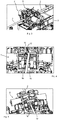
- a drilling device 1 according to the invention is shown in a perspective view.
- the drilling device 1 is used, for example, to carry out core bores or for surveying, a suitable drill rod 2 being used in each case for this purpose.
- two drill rods 2 are shown by way of example, wherein several drill rods 2 can be connected to one another via respective threaded connections to form a long drill string for very deep core bores.
- the drilling device 1 according to the invention has a guide frame 3 and a guide table 4, the guide table 4 being mounted on the guide frame 3 so as to be movable in a longitudinal direction 5 of the guide frame 3.
- the drilling device 1 has a drill drive 6, a rod catching device 7, a rod breaking device 8 and a rod pushing device 9.
- the drilling device 1 is arranged on a transport frame 10, with three lifting cylinders 11 serving to align the transport frame 10.
- a mechanical support 12 and hydraulic cylinders 14 are attached to the transport frame 10, and the drilling device 1 can be positioned at a desired drilling angle via the mechanical support 12 and the hydraulic cylinders 14.
- a conveyor trough 15 is also attached to the guide frame 3 and serves to receive the cores obtained during core drilling.
- the drill drive 6 is fastened to the guide table 4 and has a motor-driven clamping head for rotating the drill rod 2 and a rod bushing 19, which are shown in Figure 2 is shown.
- the rod bushing 19 enables a drill rod 2 released by the clamping head to be pulled through the drill drive 6, the clamping head being designed as a hollow spindle for this purpose.
- the drill drive 6 further comprises a spur gear and a hydraulic motor, which are not shown in detail in the figures, since they are known from the prior art.
- the linkage interception device 7 and the linkage breaking device 8 are attached to the guide frame 3 and in the Figures 3 to 5 shown in more detail, the rod breaking device 8 being arranged between the drill drive 6 and the rod intercepting device 7.
- the rod interception device 7 has guide rollers 16 which serve to guide the drill rod 2 during drilling and of which in FIG Figure 4 only three of the four guide rollers 16 can be seen, and a clamping device 17 (see for example Figure 4 ), which is used to clamp the drill rod 2, the clamping device 17 is not in operation during drilling, but releases the drill rod 2.
- the rod breaking device 8 has clamping pieces 18 rotatable about a drilling axis 32, which are used, for example, to loosen a threaded connection between two drill rods 2 by the clamping device 17 of the rod intercepting device 7 clamping a first drill rod 2, the clamping pieces 18 of the rod breaking device 8, clamp a second drill rod 2, which is connected to the first drill rod 2 via a threaded connection, and the clamping pieces 18 are rotated relative to the clamping device 17 about the drilling axis 32, around the position between the rod intercepting device 7 and the rod breaking device 8 arranged threaded connection of the two drill rods 2 to loosen.
- the drill drive 6 is arranged between the rod interception device 7 and the rod pusher device 9, the rod pusher device 9 being attached to an extension of the guide frame 3 and being arranged between the conveyor trough 15 and the drill drive 6.
- the linkage pusher 9 is in the Figures 6 to 8 shown in more detail and can be positively connected to the drill rod 2, the rod pushing device 9 being designed to move the drill rod 2 in the longitudinal direction 5 of the guide frame 3.
- the rod pushing device 9 has a support bracket 20, via which the rod pushing device 9 is attached to the extension of the guide frame 3, and a housing 21.
- two drive motors 22a, 22b are arranged on the housing 21 (see FIG Figure 6 ), each of the two drive motors 22a and 22b being drive-connected to a transport roller 23a or 23b of a pair of transport rollers 23a, 23b.
- the two transport rollers 23a and 23b are each arched inward, ie concave, so that the transport rollers 23a and 23b securely grip the drill rod 2 between them (see, for example Figure 7 ).
- only one drive motor can be provided for an alternative embodiment, which is drive-connected either to both transport rollers 23a and 23b or to only one of the two transport rollers 23a or 23b.
- the rod pushing device 9 is only in operation to transport a drill string consisting of several drill rods 2 out of a borehole or into a borehole, this being the case when a defective drill head is replaced or for measuring purposes.
- the transport rollers 23a and 23b are movably mounted, the two transport rollers 23a, 23b towards each other (around the drill string clamp) or away from each other (to release the drill string) are movably mounted.
- the mobility of at least one of the two transport rollers 23a, 23b makes it possible for the pair of transport rollers 23a, 23b to clamp or release the drill rod 2 between them in a non-positive manner, with the transport rollers 23a, 23b being subjected to a corresponding radial force during clamping, so that a sufficiently high coefficient of friction is created to transport long drill strings.
- the mobility of the transport rollers 23a or 23 shown in the exemplary embodiment is realized in that the rod pushing device 9 has two pressure brackets 24a and 24b, with FIG Figure 8 the pressure consoles 24a and 24b are not shown.
- Each individual pressure bracket 24a, 24b can be moved transversely to the longitudinal direction 15 of the guide frame 3, a transport roller 23a, 23b being rotatably mounted on each printing bracket 24a, 24b and being driven by the assigned drive motor 22a, 22b.
- Each pressure bracket 24a, 24b is drive-connected and movably mounted in the housing 21 with the aid of a hydraulically operated pressure cylinder 25a, 25b, with a respective pressure cylinder 25a, 25b transferring an associated pressure bracket 24a, 24b to or from the other pressure bracket 24a, 24b other print console 24a, 24b moved away from the direction.
- the linkage pusher device 9 has a pair of guide rollers 26a and 26b which are rotatable on the linkage pusher device 9 stored and the drill pipe 2 are formed leading between them.
- the guide rollers 26a, 26b like the transport rollers 23a, 23b, are mounted such that they can move towards one another, whereby it is alternatively also conceivable that only one guide roller 26a or 26b is mounted movably towards the other guide roller 26a or 26b or away from the other guide roller 26a or 26b is.
- the mobility transversely to the longitudinal direction 5 of the guide frame is realized with the aid of pressure pieces 27a, 27b.
- the pressure pieces 27a and 27b are movably mounted transversely to the longitudinal direction 5 of the guide frame 3, one of the guide rollers 26a, 26b of the pair of guide rollers 26a, 26b being rotatably mounted on each pressure piece 27a, 27b.
- Each pressure piece 27a, 27b is a mechanical pressure element 28a, 28b (see Figure 8 ) assigned, each in the form of a compression spring and arranged within a cover open to the housing 21.
- a respective pressure element 28a, 28b exerts a pressure force urging the assigned pressure piece 27a, 27b transversely to the longitudinal direction 5 of the guide frame 3 and moving the guide rollers 26a, 26b towards one another.
- a driver 29a, 29b is formed on each pressure bracket 24a, 24b, whereas each Pressure piece 27a, 27b each have a coupling shoulder 30a, 30b.
- Each of the drivers 29a, 29b rests against the coupling extension 30a, 30b assigned to it, and when the drill rod 2 is released by the transport rollers 23a, 23b moved away from each other, the guide rollers 26a, 26b are also moved away from each other by the drivers 29a, 29b Move pressure pieces 27a, 27b away from one another via the respective coupling lugs 30a, 30b, whereby the guide rollers 26a, 26b, which are rotatably mounted on the respective pressure piece 27a, 27b, move away from one another.
- the rod pushing device 9 has a spacer 31 which ensures that when the drill rod 2 is clamped, the guide rollers 23a, 23b are arranged at a greater distance from the drill rod 2 than the transport rollers 23a, 23b mounted on the corresponding pressure bracket 24a, 24b.
- the spacer 31 is arranged between the pair of guide rollers 26a, 26b and parallel to a drilling axis 32 of the drill rod 2. In addition, the spacer 31 blocks a movement of the pressure pieces 27a, 27b over the drilling axis 32 (see for example Figure 8 ).
- a drilling device 1 with a rod pusher device 9 has been presented above, the rod pusher device enabling quick insertion and recovery of very long drill strings of, for example, 50-100 meters into or out of a very deep borehole.
- the rod pushing device 9 is attached to the drilling device 1 as an additional functional unit.
- Transport rollers 23a, 23b are driven via one or two drive motors 22a, 22b, the transport rollers 23a, 23b being subjected to a corresponding radial force for transporting a drill string, so that a sufficiently high coefficient of friction is created to transport a long drill string.
- the rotary movement of the driven transport rollers 23a, 23b transports the drill string in the axial direction (longitudinal direction 5 of the guide frame 3).
- the transport path of the drill rod can be measured and the output value can be processed accordingly via a rotary encoder, which is fastened on an axis of the transport rollers 23a, 23b, and a control connected to the rotary encoder.
- Two additional guide roles 26a, 26b ensure that the drill rod 2 is held in the drilling axis 32 of the drilling device 1.
- the rod pushing device 9 is designed such that the drill string is always moved in the center of the drilling axis 32.
- the pressure of the transport rollers 23a, 23b can be released and reapplied via an adjustment mechanism, so that certain functions can be performed on the drilling device 1 despite the attached rod pusher device 9, such as rotating the drill string with the aid of a clamping head and the Ver - and end screws of the threaded connections with the help of a clamping head.
- the rod pushing device 9 is designed so that it can be adapted to existing drilling devices 1 in the area of the guide frame 3.
- linkage pushing device 9 can also have several pairs of transport rollers and / or several pairs of guide rollers, even if only one pair of transport rollers 23a, 23b and guide rollers 26a, 26b is shown in the exemplary embodiment shown in the figures .
- the invention includes everything that is contained in the description and / or shown in the drawing, including that which deviates from the specific exemplary embodiment and is obvious to the person skilled in the art.
Landscapes
- Engineering & Computer Science (AREA)
- Life Sciences & Earth Sciences (AREA)
- Geology (AREA)
- Mining & Mineral Resources (AREA)
- Physics & Mathematics (AREA)
- Environmental & Geological Engineering (AREA)
- Fluid Mechanics (AREA)
- General Life Sciences & Earth Sciences (AREA)
- Geochemistry & Mineralogy (AREA)
- Mechanical Engineering (AREA)
- Earth Drilling (AREA)
Claims (12)
- Dispositif de forage (1) présentant un cadre de guidage (3), une table de guidage (4) montée de façon à pouvoir être déplacée sur le cadre de guidage (3) dans une direction longitudinale (5) du cadre de guidage (3), et un entraînement de forage (6) fixé sur la table de guidage (4), lequel comporte une tête de serrage entraînée par un moteur pour l'entraînement rotatif d'une tige de forage (2) et un passage de tige (19) permettant de tirer une tige de forage (2) libérée par la tête de serrage à travers l'entraînement de forage (6),
caractérisé en ce que
un dispositif de poussée de tige (9) apte à être relié à force à la tige de forage (2) est fixé sur le cadre de guidage (3), et la tige de forage (2) est réalisée de manière à se déplacer dans la direction longitudinale (5) du cadre de guidage (3). - Dispositif de forage (1) selon la revendication 1,
caractérisé en ce que le dispositif de poussée de tige (9) présente au moins un moteur d'entraînement (22a, 22b) et au moins une paire de rouleaux de transport (23a, 23b), parmi lesquels un rouleau de transport (23a, 23b) est relié en entraînement à l'au moins un moteur d'entraînement (22a, 22b), dans lequel au moins un rouleau de transport (23a, 23b) de l'au moins une paire de rouleaux de transport (23a, 23b) peut être déplacé vers l'autre rouleau de transport (23a, 23b) de l'au moins une paire de rouleaux de transport (23a, 23b) ou peut être éloigné de l'autre rouleau de transport (23a, 23b) de l'au moins une paire de rouleaux de transport (23a, 23b), dans lequel l'au moins une paire de rouleaux de transport (23a, 23b) est réalisée de manière à serrer la tige de forage (2) à force entre elle ou à libérer celle-ci. - Dispositif de forage (1) selon la revendication 2,
caractérisé en ce que le dispositif de poussée de tige (9) présente au moins une console de pression (24a, 24b), laquelle est réalisée de manière à pouvoir se déplacer transversalement à la direction longitudinale (5) du cadre de guidage (3) et sur laquelle un rouleau de transport (23a, 23b) de l'au moins une paire de rouleaux de transport (23a, 23b) est monté de façon rotative. - Dispositif de forage (1) selon la revendication 3,
caractérisé en ce que le dispositif de poussée de tige (9) présente au moins une paire de rouleaux de guidage (26a, 26b), dans lequel au moins un rouleau de guidage (26a, 26b) de l'au moins une paire de rouleaux de guidage (26a, 26b) peut être déplacé vers l'autre rouleau de guidage (26a, 26b) de l'au moins une paire de rouleaux de guidage (26a, 26b) ou peut être éloigné de l'autre rouleau de guidage (26a, 26b) de l'au moins une paire de rouleaux de guidage (26a, 26b), dans lequel l'au moins une paire de rouleaux de guidage (26a, 26b) est réalisée de manière à guider la tige de forage (2) entre elle. - Dispositif de forage (1) selon la revendication 4,
caractérisé en ce que le dispositif de poussée de tige (9) présente au moins une pièce de pression (27a, 27b), laquelle est réalisée de manière à pouvoir se déplacer transversalement à la direction longitudinale (5) du cadre de guidage (3) et sur laquelle un rouleau de guidage (26a, 26b) de l'au moins une paire de rouleaux de guidage (26a, 26b) est monté de façon rotative. - Dispositif de forage (1) selon la revendication 5,
caractérisé en ce que le dispositif de poussée de tige (9) présente au moins un élément de pression mécanique (28a, 28b), lequel exerce une force de pression pressant l'au moins une pièce de pression (27a, 27b) transversalement à la direction longitudinale (5) du cadre de guidage (3) et déplaçant les rouleaux de guidage (26a, 26b) l'un vers l'autre. - Dispositif de forage (1) selon la revendication 6,
caractérisé en ce que l'au moins une console de pression (24a, 24b) présente un entraîneur (29a, 29b) s'applique de telle façon sur un embout d'accouplement (30a, 30b) réalisé sur l'au moins une pièce de pression (27a, 27b), que l'entraîneur (29a, 29b) est réalisé de manière à éloigner les rouleaux de guidage (26a, 26b) l'un de l'autre lors d'un éloignement des rouleaux de transport (23a, 23b) l'un par rapport à l'autre contre la force de pression de l'au moins un élément de pression mécanique (28a, 28b) pour libérer la tige de forage (2). - Dispositif de forage (1) selon la revendication 5,
caractérisé en ce que le dispositif de poussée de tige (9) présente un espaceur (31), lequel est disposé entre l'au moins une paire de rouleaux de guidage (26a, 26b) et parallèlement à un axe de forage (32) de la tige de forage (2) et bloque un déplacement de l'au moins une pièce de pression (27a, 27b) au-delà de l'axe de forage (32). - Dispositif de forage (1) selon la revendication 1,
caractérisé en ce qu'un dispositif d'interception de tige (7) est fixé avec un dispositif de serrage (17) au cadre de guidage (3), dans lequel la tige de forage (2) peut être serrée à l'aide du dispositif de serrage (17). - Dispositif de forage (1) selon la revendication 9,
caractérisé en ce que l'entraînement de forage (6) est disposé entre le dispositif d'interception de tige (7) et le dispositif de poussée de tige (9). - Dispositif de forage (1) selon la revendication 10, caractérisé en ce qu'un dispositif de rupture de tige (8) est disposé entre le dispositif d'interception de tige (7) et l'entraînement de forage (6).
- Dispositif de forage (1) selon la revendication 1,
caractérisé en ce que la tête de serrage est réalisée comme une broche creuse.
Priority Applications (2)
| Application Number | Priority Date | Filing Date | Title |
|---|---|---|---|
| PL18185397T PL3599340T3 (pl) | 2018-07-25 | 2018-07-25 | Przyrząd wiertniczy |
| EP18185397.9A EP3599340B1 (fr) | 2018-07-25 | 2018-07-25 | Dispositif de forage |
Applications Claiming Priority (1)
| Application Number | Priority Date | Filing Date | Title |
|---|---|---|---|
| EP18185397.9A EP3599340B1 (fr) | 2018-07-25 | 2018-07-25 | Dispositif de forage |
Publications (2)
| Publication Number | Publication Date |
|---|---|
| EP3599340A1 EP3599340A1 (fr) | 2020-01-29 |
| EP3599340B1 true EP3599340B1 (fr) | 2020-12-23 |
Family
ID=63047163
Family Applications (1)
| Application Number | Title | Priority Date | Filing Date |
|---|---|---|---|
| EP18185397.9A Active EP3599340B1 (fr) | 2018-07-25 | 2018-07-25 | Dispositif de forage |
Country Status (2)
| Country | Link |
|---|---|
| EP (1) | EP3599340B1 (fr) |
| PL (1) | PL3599340T3 (fr) |
Families Citing this family (2)
| Publication number | Priority date | Publication date | Assignee | Title |
|---|---|---|---|---|
| CN113089639B (zh) * | 2021-04-21 | 2022-03-18 | 郑州工业应用技术学院 | 一种土木工程用基坑稳固组件 |
| CN113565453A (zh) * | 2021-08-13 | 2021-10-29 | 王超 | 一种阻力感应钻杆推送装置 |
Citations (1)
| Publication number | Priority date | Publication date | Assignee | Title |
|---|---|---|---|---|
| EP2093373A1 (fr) * | 2008-02-21 | 2009-08-26 | Klemm Bohrtechnik GmbH | Dispositif de forage, en particulier pour l'établissement de trous de mine sur le sol d'un cours d'eau, et procédé d'introduction d'une charge d'explosif dans le sol d'un cours d'eau |
Family Cites Families (4)
| Publication number | Priority date | Publication date | Assignee | Title |
|---|---|---|---|---|
| DE4038424C1 (en) * | 1990-12-01 | 1992-04-09 | Ing. Guenter Klemm Bohrtechnik Gmbh, 5962 Drolshagen, De | Kelly borehole drilling arrangement - involves telescopically nested pipes connected to drill head |
| DK2505762T3 (en) * | 2011-03-30 | 2018-05-28 | Abs Trenchless Zweigniederlassung Der Klemm Bohrtechnik Gmbh | Drilling device and method for horizontal drilling |
| DE102012010199B4 (de) * | 2012-05-16 | 2014-07-31 | Klemm Bohrtechnik Gmbh | Verfahren und Vorrichtung zum Erstellen eines Bohrloches |
| CL2017001229A1 (es) * | 2016-05-13 | 2018-08-10 | Dr Fabrication Inc | Un dispositivo de posicionamiento de barra |
-
2018
- 2018-07-25 EP EP18185397.9A patent/EP3599340B1/fr active Active
- 2018-07-25 PL PL18185397T patent/PL3599340T3/pl unknown
Patent Citations (1)
| Publication number | Priority date | Publication date | Assignee | Title |
|---|---|---|---|---|
| EP2093373A1 (fr) * | 2008-02-21 | 2009-08-26 | Klemm Bohrtechnik GmbH | Dispositif de forage, en particulier pour l'établissement de trous de mine sur le sol d'un cours d'eau, et procédé d'introduction d'une charge d'explosif dans le sol d'un cours d'eau |
Also Published As
| Publication number | Publication date |
|---|---|
| EP3599340A1 (fr) | 2020-01-29 |
| PL3599340T3 (pl) | 2021-06-28 |
Similar Documents
| Publication | Publication Date | Title |
|---|---|---|
| DE3114612C2 (de) | Bohrvorrichtung für Hartgestein | |
| EP1679462B1 (fr) | Appareil pour pose de tuyau | |
| EP2728104B1 (fr) | Procédé de réalisation d'un forage horizontal dans le sol et dispositif de forage horizontal | |
| DE102009035277B4 (de) | Bohrvorrichtung | |
| EP0527460A2 (fr) | Procédé et dispositif pour forer des trous dans le sol ou dans la roche, notamment pour le placement de boulons d'ancrage à injection | |
| DE2540590A1 (de) | Verfahren und vorrichtung zur durchfuehrung einer bohrung unterhalb eines hindernisses laengs einer bogenfoermigen bahn | |
| EP2553202B1 (fr) | Procédé pour faire fonctionner un dispositif de forage horizontal et dispositif de forage horizontal | |
| EP3599340B1 (fr) | Dispositif de forage | |
| EP0796978A2 (fr) | Magasin pour tiges de forage | |
| EP2351903A2 (fr) | Procédé et agencement de fabrication et/ou d'élargissement d'un trou dans la terre | |
| EP2737159B1 (fr) | Manchon porte-outil recevant des outils de forage tubulaires présentant de différents diamètres | |
| DE29502091U1 (de) | Vorrichtung zum Handhaben von Rohren eines Bohrgestänges | |
| WO2000075479A1 (fr) | Dispositif de transfert de tiges de forage | |
| EP2553203B1 (fr) | Dispositif de forage horizontal | |
| EP3456914B1 (fr) | Dispositif de forage double tête et procédé de réalisation d'un forage | |
| DE29706264U1 (de) | Vorrichtung zum Doppelkof- und Überlagerungsbohren | |
| DE19527138C1 (de) | Vorrichtung zum Ersetzen einer alten Versorgungsleitung durch eine neue Leitung | |
| DE3513194C1 (de) | Vorrichtung zum Durchdringen oberflächennaher Bodenschichten | |
| EP1407112A1 (fr) | Procede permettant de realiser des sondages | |
| EP2626506B1 (fr) | Dispositif de déplacement d'un moyen de travail dans la terre | |
| DE69412803T2 (de) | Gestängebehälter für felsbohrausrüstungen | |
| DE3336314C1 (de) | Bohrlafette | |
| DE1922320C3 (de) | Werkzeugwechselvorrichtung | |
| DE102011101442B4 (de) | "Verfahren zum Durchführen einer Erdbohrung von einer Startbaugrube mit einer Erdrakete und Bohrsystem mit einer Lafette für eine Erdrakete zur Positionierung der Erdrakete in einer Startbaugrube zur Durchführung einer Erdbohrung in einer vorbestimmten Tiefe" | |
| DE10123250B4 (de) | Bohr-und Ankersetzgerät mit Bohrstangenzentrierung |
Legal Events
| Date | Code | Title | Description |
|---|---|---|---|
| PUAI | Public reference made under article 153(3) epc to a published international application that has entered the european phase |
Free format text: ORIGINAL CODE: 0009012 |
|
| STAA | Information on the status of an ep patent application or granted ep patent |
Free format text: STATUS: THE APPLICATION HAS BEEN PUBLISHED |
|
| AK | Designated contracting states |
Kind code of ref document: A1 Designated state(s): AL AT BE BG CH CY CZ DE DK EE ES FI FR GB GR HR HU IE IS IT LI LT LU LV MC MK MT NL NO PL PT RO RS SE SI SK SM TR |
|
| AX | Request for extension of the european patent |
Extension state: BA ME |
|
| STAA | Information on the status of an ep patent application or granted ep patent |
Free format text: STATUS: REQUEST FOR EXAMINATION WAS MADE |
|
| 17P | Request for examination filed |
Effective date: 20200729 |
|
| RBV | Designated contracting states (corrected) |
Designated state(s): AL AT BE BG CH CY CZ DE DK EE ES FI FR GB GR HR HU IE IS IT LI LT LU LV MC MK MT NL NO PL PT RO RS SE SI SK SM TR |
|
| GRAP | Despatch of communication of intention to grant a patent |
Free format text: ORIGINAL CODE: EPIDOSNIGR1 |
|
| STAA | Information on the status of an ep patent application or granted ep patent |
Free format text: STATUS: GRANT OF PATENT IS INTENDED |
|
| RIC1 | Information provided on ipc code assigned before grant |
Ipc: E21B 7/04 20060101AFI20200922BHEP Ipc: E21B 19/16 20060101ALI20200922BHEP |
|
| INTG | Intention to grant announced |
Effective date: 20201013 |
|
| GRAS | Grant fee paid |
Free format text: ORIGINAL CODE: EPIDOSNIGR3 |
|
| GRAA | (expected) grant |
Free format text: ORIGINAL CODE: 0009210 |
|
| STAA | Information on the status of an ep patent application or granted ep patent |
Free format text: STATUS: THE PATENT HAS BEEN GRANTED |
|
| AK | Designated contracting states |
Kind code of ref document: B1 Designated state(s): AL AT BE BG CH CY CZ DE DK EE ES FI FR GB GR HR HU IE IS IT LI LT LU LV MC MK MT NL NO PL PT RO RS SE SI SK SM TR |
|
| REG | Reference to a national code |
Ref country code: GB Ref legal event code: FG4D Free format text: NOT ENGLISH |
|
| REG | Reference to a national code |
Ref country code: DE Ref legal event code: R096 Ref document number: 502018003389 Country of ref document: DE |
|
| REG | Reference to a national code |
Ref country code: AT Ref legal event code: REF Ref document number: 1347891 Country of ref document: AT Kind code of ref document: T Effective date: 20210115 Ref country code: DE Ref legal event code: R082 Ref document number: 502018003389 Country of ref document: DE Representative=s name: ZENZ PATENTANWAELTE PARTNERSCHAFT MBB, DE |
|
| REG | Reference to a national code |
Ref country code: IE Ref legal event code: FG4D Free format text: LANGUAGE OF EP DOCUMENT: GERMAN |
|
| REG | Reference to a national code |
Ref country code: SE Ref legal event code: TRGR |
|
| PG25 | Lapsed in a contracting state [announced via postgrant information from national office to epo] |
Ref country code: RS Free format text: LAPSE BECAUSE OF FAILURE TO SUBMIT A TRANSLATION OF THE DESCRIPTION OR TO PAY THE FEE WITHIN THE PRESCRIBED TIME-LIMIT Effective date: 20201223 Ref country code: FI Free format text: LAPSE BECAUSE OF FAILURE TO SUBMIT A TRANSLATION OF THE DESCRIPTION OR TO PAY THE FEE WITHIN THE PRESCRIBED TIME-LIMIT Effective date: 20201223 Ref country code: GR Free format text: LAPSE BECAUSE OF FAILURE TO SUBMIT A TRANSLATION OF THE DESCRIPTION OR TO PAY THE FEE WITHIN THE PRESCRIBED TIME-LIMIT Effective date: 20210324 Ref country code: NO Free format text: LAPSE BECAUSE OF FAILURE TO SUBMIT A TRANSLATION OF THE DESCRIPTION OR TO PAY THE FEE WITHIN THE PRESCRIBED TIME-LIMIT Effective date: 20210323 |
|
| REG | Reference to a national code |
Ref country code: NL Ref legal event code: MP Effective date: 20201223 |
|
| PG25 | Lapsed in a contracting state [announced via postgrant information from national office to epo] |
Ref country code: BG Free format text: LAPSE BECAUSE OF FAILURE TO SUBMIT A TRANSLATION OF THE DESCRIPTION OR TO PAY THE FEE WITHIN THE PRESCRIBED TIME-LIMIT Effective date: 20210323 Ref country code: LV Free format text: LAPSE BECAUSE OF FAILURE TO SUBMIT A TRANSLATION OF THE DESCRIPTION OR TO PAY THE FEE WITHIN THE PRESCRIBED TIME-LIMIT Effective date: 20201223 |
|
| PG25 | Lapsed in a contracting state [announced via postgrant information from national office to epo] |
Ref country code: NL Free format text: LAPSE BECAUSE OF FAILURE TO SUBMIT A TRANSLATION OF THE DESCRIPTION OR TO PAY THE FEE WITHIN THE PRESCRIBED TIME-LIMIT Effective date: 20201223 Ref country code: HR Free format text: LAPSE BECAUSE OF FAILURE TO SUBMIT A TRANSLATION OF THE DESCRIPTION OR TO PAY THE FEE WITHIN THE PRESCRIBED TIME-LIMIT Effective date: 20201223 |
|
| REG | Reference to a national code |
Ref country code: LT Ref legal event code: MG9D |
|
| PG25 | Lapsed in a contracting state [announced via postgrant information from national office to epo] |
Ref country code: SM Free format text: LAPSE BECAUSE OF FAILURE TO SUBMIT A TRANSLATION OF THE DESCRIPTION OR TO PAY THE FEE WITHIN THE PRESCRIBED TIME-LIMIT Effective date: 20201223 Ref country code: CZ Free format text: LAPSE BECAUSE OF FAILURE TO SUBMIT A TRANSLATION OF THE DESCRIPTION OR TO PAY THE FEE WITHIN THE PRESCRIBED TIME-LIMIT Effective date: 20201223 Ref country code: EE Free format text: LAPSE BECAUSE OF FAILURE TO SUBMIT A TRANSLATION OF THE DESCRIPTION OR TO PAY THE FEE WITHIN THE PRESCRIBED TIME-LIMIT Effective date: 20201223 Ref country code: LT Free format text: LAPSE BECAUSE OF FAILURE TO SUBMIT A TRANSLATION OF THE DESCRIPTION OR TO PAY THE FEE WITHIN THE PRESCRIBED TIME-LIMIT Effective date: 20201223 Ref country code: PT Free format text: LAPSE BECAUSE OF FAILURE TO SUBMIT A TRANSLATION OF THE DESCRIPTION OR TO PAY THE FEE WITHIN THE PRESCRIBED TIME-LIMIT Effective date: 20210423 Ref country code: RO Free format text: LAPSE BECAUSE OF FAILURE TO SUBMIT A TRANSLATION OF THE DESCRIPTION OR TO PAY THE FEE WITHIN THE PRESCRIBED TIME-LIMIT Effective date: 20201223 Ref country code: SK Free format text: LAPSE BECAUSE OF FAILURE TO SUBMIT A TRANSLATION OF THE DESCRIPTION OR TO PAY THE FEE WITHIN THE PRESCRIBED TIME-LIMIT Effective date: 20201223 |
|
| REG | Reference to a national code |
Ref country code: DE Ref legal event code: R097 Ref document number: 502018003389 Country of ref document: DE |
|
| PG25 | Lapsed in a contracting state [announced via postgrant information from national office to epo] |
Ref country code: IS Free format text: LAPSE BECAUSE OF FAILURE TO SUBMIT A TRANSLATION OF THE DESCRIPTION OR TO PAY THE FEE WITHIN THE PRESCRIBED TIME-LIMIT Effective date: 20210423 |
|
| PG25 | Lapsed in a contracting state [announced via postgrant information from national office to epo] |
Ref country code: AL Free format text: LAPSE BECAUSE OF FAILURE TO SUBMIT A TRANSLATION OF THE DESCRIPTION OR TO PAY THE FEE WITHIN THE PRESCRIBED TIME-LIMIT Effective date: 20201223 |
|
| PLBE | No opposition filed within time limit |
Free format text: ORIGINAL CODE: 0009261 |
|
| STAA | Information on the status of an ep patent application or granted ep patent |
Free format text: STATUS: NO OPPOSITION FILED WITHIN TIME LIMIT |
|
| PG25 | Lapsed in a contracting state [announced via postgrant information from national office to epo] |
Ref country code: DK Free format text: LAPSE BECAUSE OF FAILURE TO SUBMIT A TRANSLATION OF THE DESCRIPTION OR TO PAY THE FEE WITHIN THE PRESCRIBED TIME-LIMIT Effective date: 20201223 |
|
| 26N | No opposition filed |
Effective date: 20210924 |
|
| PG25 | Lapsed in a contracting state [announced via postgrant information from national office to epo] |
Ref country code: ES Free format text: LAPSE BECAUSE OF FAILURE TO SUBMIT A TRANSLATION OF THE DESCRIPTION OR TO PAY THE FEE WITHIN THE PRESCRIBED TIME-LIMIT Effective date: 20201223 |
|
| PG25 | Lapsed in a contracting state [announced via postgrant information from national office to epo] |
Ref country code: SI Free format text: LAPSE BECAUSE OF FAILURE TO SUBMIT A TRANSLATION OF THE DESCRIPTION OR TO PAY THE FEE WITHIN THE PRESCRIBED TIME-LIMIT Effective date: 20201223 |
|
| REG | Reference to a national code |
Ref country code: CH Ref legal event code: PL |
|
| PG25 | Lapsed in a contracting state [announced via postgrant information from national office to epo] |
Ref country code: MC Free format text: LAPSE BECAUSE OF FAILURE TO SUBMIT A TRANSLATION OF THE DESCRIPTION OR TO PAY THE FEE WITHIN THE PRESCRIBED TIME-LIMIT Effective date: 20201223 |
|
| REG | Reference to a national code |
Ref country code: BE Ref legal event code: MM Effective date: 20210731 |
|
| PG25 | Lapsed in a contracting state [announced via postgrant information from national office to epo] |
Ref country code: LI Free format text: LAPSE BECAUSE OF NON-PAYMENT OF DUE FEES Effective date: 20210731 Ref country code: CH Free format text: LAPSE BECAUSE OF NON-PAYMENT OF DUE FEES Effective date: 20210731 |
|
| PG25 | Lapsed in a contracting state [announced via postgrant information from national office to epo] |
Ref country code: IS Free format text: LAPSE BECAUSE OF FAILURE TO SUBMIT A TRANSLATION OF THE DESCRIPTION OR TO PAY THE FEE WITHIN THE PRESCRIBED TIME-LIMIT Effective date: 20210423 Ref country code: LU Free format text: LAPSE BECAUSE OF NON-PAYMENT OF DUE FEES Effective date: 20210725 Ref country code: FR Free format text: LAPSE BECAUSE OF NON-PAYMENT OF DUE FEES Effective date: 20210731 |
|
| PG25 | Lapsed in a contracting state [announced via postgrant information from national office to epo] |
Ref country code: IE Free format text: LAPSE BECAUSE OF NON-PAYMENT OF DUE FEES Effective date: 20210725 Ref country code: BE Free format text: LAPSE BECAUSE OF NON-PAYMENT OF DUE FEES Effective date: 20210731 |
|
| P01 | Opt-out of the competence of the unified patent court (upc) registered |
Effective date: 20230503 |
|
| PG25 | Lapsed in a contracting state [announced via postgrant information from national office to epo] |
Ref country code: CY Free format text: LAPSE BECAUSE OF FAILURE TO SUBMIT A TRANSLATION OF THE DESCRIPTION OR TO PAY THE FEE WITHIN THE PRESCRIBED TIME-LIMIT Effective date: 20201223 |
|
| PG25 | Lapsed in a contracting state [announced via postgrant information from national office to epo] |
Ref country code: HU Free format text: LAPSE BECAUSE OF FAILURE TO SUBMIT A TRANSLATION OF THE DESCRIPTION OR TO PAY THE FEE WITHIN THE PRESCRIBED TIME-LIMIT; INVALID AB INITIO Effective date: 20180725 |
|
| PGFP | Annual fee paid to national office [announced via postgrant information from national office to epo] |
Ref country code: IT Payment date: 20230724 Year of fee payment: 6 Ref country code: GB Payment date: 20230721 Year of fee payment: 6 |
|
| PGFP | Annual fee paid to national office [announced via postgrant information from national office to epo] |
Ref country code: SE Payment date: 20230719 Year of fee payment: 6 Ref country code: PL Payment date: 20230714 Year of fee payment: 6 Ref country code: DE Payment date: 20230731 Year of fee payment: 6 |
|
| PG25 | Lapsed in a contracting state [announced via postgrant information from national office to epo] |
Ref country code: MK Free format text: LAPSE BECAUSE OF FAILURE TO SUBMIT A TRANSLATION OF THE DESCRIPTION OR TO PAY THE FEE WITHIN THE PRESCRIBED TIME-LIMIT Effective date: 20201223 |
|
| PG25 | Lapsed in a contracting state [announced via postgrant information from national office to epo] |
Ref country code: TR Free format text: LAPSE BECAUSE OF FAILURE TO SUBMIT A TRANSLATION OF THE DESCRIPTION OR TO PAY THE FEE WITHIN THE PRESCRIBED TIME-LIMIT Effective date: 20201223 |
|
| REG | Reference to a national code |
Ref country code: AT Ref legal event code: MM01 Ref document number: 1347891 Country of ref document: AT Kind code of ref document: T Effective date: 20230725 |