EP3599131B1 - Scheinwerfer für ein kraftfahrzeug - Google Patents
Scheinwerfer für ein kraftfahrzeug Download PDFInfo
- Publication number
- EP3599131B1 EP3599131B1 EP19181032.4A EP19181032A EP3599131B1 EP 3599131 B1 EP3599131 B1 EP 3599131B1 EP 19181032 A EP19181032 A EP 19181032A EP 3599131 B1 EP3599131 B1 EP 3599131B1
- Authority
- EP
- European Patent Office
- Prior art keywords
- adjusting element
- adjusting
- actuator
- headlamp according
- axis
- Prior art date
- Legal status (The legal status is an assumption and is not a legal conclusion. Google has not performed a legal analysis and makes no representation as to the accuracy of the status listed.)
- Active
Links
Images




Classifications
-
- B—PERFORMING OPERATIONS; TRANSPORTING
- B60—VEHICLES IN GENERAL
- B60Q—ARRANGEMENT OF SIGNALLING OR LIGHTING DEVICES, THE MOUNTING OR SUPPORTING THEREOF OR CIRCUITS THEREFOR, FOR VEHICLES IN GENERAL
- B60Q1/00—Arrangement of optical signalling or lighting devices, the mounting or supporting thereof or circuits therefor
- B60Q1/02—Arrangement of optical signalling or lighting devices, the mounting or supporting thereof or circuits therefor the devices being primarily intended to illuminate the way ahead or to illuminate other areas of way or environments
- B60Q1/04—Arrangement of optical signalling or lighting devices, the mounting or supporting thereof or circuits therefor the devices being primarily intended to illuminate the way ahead or to illuminate other areas of way or environments the devices being headlights
- B60Q1/06—Arrangement of optical signalling or lighting devices, the mounting or supporting thereof or circuits therefor the devices being primarily intended to illuminate the way ahead or to illuminate other areas of way or environments the devices being headlights adjustable, e.g. remotely-controlled from inside vehicle
- B60Q1/076—Arrangement of optical signalling or lighting devices, the mounting or supporting thereof or circuits therefor the devices being primarily intended to illuminate the way ahead or to illuminate other areas of way or environments the devices being headlights adjustable, e.g. remotely-controlled from inside vehicle by electrical means including means to transmit the movements, e.g. shafts or joints
-
- B—PERFORMING OPERATIONS; TRANSPORTING
- B60—VEHICLES IN GENERAL
- B60Q—ARRANGEMENT OF SIGNALLING OR LIGHTING DEVICES, THE MOUNTING OR SUPPORTING THEREOF OR CIRCUITS THEREFOR, FOR VEHICLES IN GENERAL
- B60Q1/00—Arrangement of optical signalling or lighting devices, the mounting or supporting thereof or circuits therefor
- B60Q1/02—Arrangement of optical signalling or lighting devices, the mounting or supporting thereof or circuits therefor the devices being primarily intended to illuminate the way ahead or to illuminate other areas of way or environments
- B60Q1/04—Arrangement of optical signalling or lighting devices, the mounting or supporting thereof or circuits therefor the devices being primarily intended to illuminate the way ahead or to illuminate other areas of way or environments the devices being headlights
- B60Q1/06—Arrangement of optical signalling or lighting devices, the mounting or supporting thereof or circuits therefor the devices being primarily intended to illuminate the way ahead or to illuminate other areas of way or environments the devices being headlights adjustable, e.g. remotely-controlled from inside vehicle
- B60Q1/068—Arrangement of optical signalling or lighting devices, the mounting or supporting thereof or circuits therefor the devices being primarily intended to illuminate the way ahead or to illuminate other areas of way or environments the devices being headlights adjustable, e.g. remotely-controlled from inside vehicle by mechanical means
Definitions
- the invention relates to a headlight for a motor vehicle, comprising a light module that is movably mounted in a housing and adjusting means for adjusting the spatial position of the light module in the housing.
- Headlights with a dynamic headlight range control are installed in motor vehicles today, with both front headlights usually being able to be controlled accordingly for such a headlight range control.
- the aim of this headlight range control is to give the customer the best possible light on the road in every driving situation, i.e. to illuminate the area in front of the vehicle in the best possible way.
- This headlight range regulation usually takes place automatically using a corresponding actuator, via which the light module can be pivoted up and down about a horizontal axis. This requires that the headlight or the light module is brought into a defined basic setting or basic position, both in relation to the lateral alignment, i.e. the left-right alignment, and the upward and downward alignment.
- This basic setting is usually done using adjustment screws that allow horizontal and vertical alignment of the headlight or the light module.
- This basic adjustment which has to be carried out manually when the headlight is installed, in the two adjustment axes is associated with a considerable expenditure of time, either in the context of vehicle production or in the context of maintenance work.
- To provide an automatic setting instead of a manual setting is off DE 20 2011 003 404 U1 a headlight known, in which this biaxial
- the light module is adjusted to set the horizontal and vertical basic position by means of two separate actuators, with which the light module can be adjusted to the basic position about the corresponding adjustment axes.
- two such actuators is complex, and there is not always sufficient installation space for the integration of two such actuators.
- the invention is therefore based on the problem of specifying a headlight that is improved in comparison.
- the headlight according to the invention includes the features of claim 1.
- only one actuator is used to adjust the light module, which, in conjunction with a corresponding adjusting mechanism, makes it possible to carry out the corresponding adjustment both around a vertical axis for left-right alignment and around a horizontal axis Make the top-bottom alignment.
- the light module itself is arranged in a fixed position on a carrier, with the carrier being movably mounted in the housing. It can be pivoted both about a horizontal and a vertical axis, and this pivotability can be implemented, for example, via a ball joint with which the carrier is arranged on a corresponding holding structure.
- the carrier is now coupled to the one actuator with a corresponding adjusting mechanism, this adjusting mechanism being designed in such a way that, during operation of the actuator, the carrier can pivot both about the horizontal and about the vertical axis is possible.
- the actuating mechanism is designed such that the respective pivoting movements can be carried out separately, which means that the carrier can either be pivoted about the horizontal pivot axis in order to make the top-bottom alignment, or about the vertical pivot axis in order to make the right-left alignment.
- the headlight according to the invention can automatically align the light module to assume a defined basic position using only one actuator.
- the actuator is controlled via a corresponding control device, which can either be part of the headlight or to which the actuator or headlight is coupled via a corresponding interface, which means that the control device is provided on the motor vehicle side.
- the corresponding position information in relation to the activation of the actuator i.e. the target positions assumed when the horizontal basic setting position and the vertical basic setting position are reached, is stored in this control device, preferably in both the horizontal and vertical direction, since starting from in particular the vertical basic setting, the headlight range is adjusted in regular operation, within which the headlight or the light module is swiveled up or down around the horizontal axis.
- a central component of the headlight according to the invention is, as described, the actuating mechanism, which couples the actuator to the carrier and thus to the light module, and which is designed such that, despite the activation of only one actuator, which consequently only transmits a defined movement to the actuating mechanism, a separate The carrier and thus the light module are pivoted about the separate adjustment axes.
- a specific embodiment of this adjusting mechanism provides that the adjusting mechanism has a first and a second movable adjusting element, each coupled to the carrier, with the carrier being pivotable about the horizontal axis via the first adjusting element and about the vertical axis via the second adjusting element and one of which is movable via the actuator for pivoting about an axis and during movement can be temporarily brought into operative connection with the other actuating element for pivoting about the other axis.
- the adjusting mechanism thus comprises two separate, movable adjusting elements, which can also be referred to as adjusting supports or adjusting frames. Both are coupled to the carrier to which the light module is attached, so that an adjustment or movement of such an actuating element necessarily results in a corresponding adjustment or movement of the carrier.
- One control element is provided for pivoting the carrier about the horizontal axis, ie for pivoting it up and down, while the other control element is provided for pivoting about the vertical axis, ie for right-left alignment.
- the first control element that performs the pivoting of the horizontal axis is preferably also used at the same time to perform the pivoting of the light module as part of the headlight range adjustment, which is why the actuator is preferably coupled to the first control element.
- the two control elements only interact with one another temporarily, that is to say they are not permanently connected to one another, but only temporarily interact with one another in an operative connection. If, for example, the actuator is coupled to the first control element, as is preferably provided, then when it is moved, the carrier and thus the light module are pivoted up and down about the horizontal axis. As part of the maximum displacement or maximum movement that can be carried out with the first control element, starting from one extreme position or from one stop position to the other stop position, i.e.
- the left-right basic setting is made, the mechanical coupling of both actuating elements can be released by moving the first actuating element back after this is no longer required, and the basic setting can be made about the horizontal axis.
- a corresponding separate pivoting about the two control axes is therefore possible by means of a corresponding geometric design of the individual control elements and their temporary mechanical coupling.
- the carrier is designed as a frame on or in which the light module is fixed in a fixed position, which frame is mounted in the area of a corner or a vertical side on a holding structure that is provided in a fixed position in or on the housing , wherein the first and the second adjusting element is mounted on the opposite side of the frame in the region of the lower and upper corners.
- the carrier or the frame is pivotably mounted on the holding structure with its upper left corner (seen from the front), the second control element is also mounted on the upper right corner on the opposite side, since, as described, both bearing points define the horizontal pivot axis .
- the first adjusting element is mounted on this opposite side at the lower right corner, so that pivoting about this upper horizontal axis is possible.
- This means that the first adjusting element is therefore preferably mounted in the area of the corner lying diagonally opposite the corner at which the carrier is mounted, while the second adjusting element is mounted in the area of the other corner essentially at the same height as the carrier.
- the carrier and the second adjusting element do not necessarily have to be fastened or mounted in the area of the upper corners. Rather, it is also conceivable to store them at a position along the vertical frame sides, but again essentially at the same height. It is only necessary for the first actuating element to be connected at a position which is offset vertically in relation to the bearing axis for the horizontal axis.
- the first and the second element are preferably each linearly movable, with the actuator being a linear actuator. Both adjusting elements are consequently guided in a linearly movable manner on corresponding guide devices, the actuator is likewise a linear motor which, as described, also serves to regulate the headlight range.
- the first and the second actuating element are temporarily coupled to one another when the first actuating element moves, for example starting from a first stop position into a second stop position, i.e. when the maximum actuating path is traversed, so that the second actuating element is carried along by the moving first actuating element will.
- the first and the second control element expediently each have a driver section, with the driver section of the control element that can be moved via the actuator, i.e. preferably the first control element, being in a detachable functional connection during the movement with the driver section of the other control element, i.e. preferably the second control element .
- a simple driver coupling is therefore provided in order to carry out the corresponding pivoting about the two axes.
- the design of the actuating elements or the arrangement of the driver sections can be such that the movement coupling only takes place when the maximum required pivoting of the carrier about the pivot axis, which can be operated via the actuating element that can be actively moved with the actuator, has taken place, i.e. about the Swivel angle, which is the maximum required within the framework of headlight range control. If, starting from the one maximum or end position, the other maximum or end position has been reached, the carrier coupling can take place, so that the right-left alignment then takes place. Upon reaching the end position in relation to the right-left alignment, the first control element can then be actively moved back via the actuator in order to carry out the horizontal alignment up-down within the maximum adjustment angle range, as required for headlight range adjustment.
- locking means are provided in order to lock the adjusting mechanism when the pivoting of the carrier about the vertical axis has ended when the basic position is reached, i.e. the locking means then block further pivoting about the vertical axis is.
- a locking means can preferably be a latching means via which the pivoting position of the actuating element causing the pivoting about the vertical axis is automatically locked. This means that when the right-left adjustment movement ends, a latch lock occurs automatically.
- the latching means can comprise a latching rail, along which the actuating element can be moved, as well as a latching section provided on the actuating element, which interacts with the latching rail, so that the latching lock is provided automatically when the basic position is reached.
- the locking means is a locking means to be set manually, for example in the form of a locking pin, which is to be set by a fitter who carries out the headlight adjustment as part of the installation or maintenance. This locking element is to be pushed, for example, into a corresponding locking hole on the actuating element, so that a corresponding further movement is blocked or the like.
- the adjustment is made by controlling the actuator using a corresponding control device, which is additionally provided for detecting position information on the carrier and/or on the first and/or second actuating element. This is necessary in order to record exact position information for the relevant positions as part of the setting operation, so that an exact position resolution is possible in order to control the basic setting, but also the later headlight range adjustment.
- the invention also relates to a motor vehicle comprising at least one headlight of the type described above.
- the invention relates to a method for adjusting a headlight of the type described above, installed in a motor vehicle, in which method the first adjusting element is moved from this defined end position via the actuator when the carrier is pivoted about the vertical axis into an end position until is pivoted by interaction of the first control element with the second control element of the support about the vertical axis in a first target position in which the second control element is locked, after which the first control element via the actuator is moved back while pivoting about the horizontal axis until the carrier has reached a second target position, the position information of the carrier and/or the first and/or the second actuating element being stored for the two target positions.
- FIG. 1 shows a headlight 1 according to the invention in the form of a pure schematic representation.
- a housing 2 of the headlight in which a light module 3, which is also only shown in principle here, is accommodated, is indicated by dashed lines.
- the light module 3 is installed in a fixed position on a carrier 4 in the form of a frame 5 .
- the frame 5 is movably mounted on a holding structure 6, which is arranged in a fixed position on the housing 2, about a first joint connection 7, preferably a ball joint, so that pivoting about a horizontal axis y as well as about a vertical axis z is possible.
- the adjusting mechanism 8 has a first adjusting element 10 which is coupled to the actuator 9, a linear actuator or a linear motor. That The first control element 10 can be moved linearly, so it can be moved linearly, as represented by the double arrow P. It is also connected in an articulated manner to the carrier 4 or to the frame 5 via an articulated connection 11, preferably again a ball joint, with the articulated connection 11 in the region of the diagonally opposite corner of the frame 5 relative to the corner at which the articulated connection 7 is provided , is arranged.
- a first driver section 12 is provided on the first adjusting element 10 and is used for the mechanical coupling to a second adjusting element 13 , which is also part of the joint mechanism 8 .
- the second adjusting element 13 is fastened to the frame 5 via a further articulated connection 14, preferably also a ball joint, specifically in the area of the upper right corner on the same level or in the same horizontal plane as the articulated connection 7, so that the articulated connection 14 consequently in the Horizontal axis y runs or defines it.
- This means that the frame 5 can be pivoted about the horizontal axis y defined between the articulations 7 and 14, which is done by moving the first adjusting element 10, as will be described below.
- a second driver projection 15 is provided on the second actuating element 13 , which engages in the U-shaped first actuating element 10 and is evidently located in the linear movement path of the first driver section 12 .
- the driver sections 12, 15 enter into a temporary mechanical coupling as part of the adjustment movement, which will be discussed below.
- a locking means 16 shown here as an example in the form of a locking rail 17, which interacts with a locking element 18, which is provided on the second actuating element 13, in order to, as will be discussed below, a corresponding adjustment position of the to be able to lock the second actuating element 13 .
- a further driver section 19 is shown on the first adjusting element 10, which is optional and which can also be used to move the second adjusting element 13 back again if necessary, should the target position be within the framework of the lateral basic setting, i.e. right-hand Left setting, having been accidentally run over.
- FIG. 2 shows the arrangement in a side view 1 , which is regarded as the starting position or starting position for the following description. It is assumed that in this position the carrier 4 or frame 5 is in an extreme position, i.e. it is pivoted to the maximum about the horizontal axis y and is in a middle position relative to the vertical axis z or, relative to the respective maximum Pan angle, positioned in the extreme position about the z-axis and a zero position about the y-axis. This corresponds e.g. B. the delivery condition of the headlight on the assembly line.
- the actuator 9, i.e. the linear motor is now activated via the in 1 control device 20, also shown only in dashed lines, which can be part of the headlight 1, but also part of the motor vehicle, is controlled accordingly, so that the first actuating element 10 is moved in the direction of the arrow P', i.e. the two driver sections 12, 15 move away from each other be moved away, like Figures 3 and 4 demonstrate. Since only the first actuating element 10 but not the second actuating element 13 is moved, the y-axis consequently remains in its spatial position, and the carrier 4 or the frame 5 is merely pivoted about the y-axis.
- the light module 3 is pivoted down, like the Figures 3 and in particular 4 clearly show. It is assumed that a pivoting starting from the zero position according to 1 5° downwards. In this position it is assumed that an extreme or stop position is taken in relation to the maximum pivoting path about the horizontal axis y. The assumed position or control data are possibly recorded and stored by the control device 20 . The Alignment of the frame 5 around the vertical axis z has not changed as a result of this adjustment movement, i.e. the frame 5 and thus also the second adjustment element 13 are still in the one lateral stop position, i.e. in a maximum lateral pivoting position around the vertical axis z .
- the first adjusting element 10 is moved again via the actuator 9 in the opposite direction, as shown by the arrow P". 6 clearly shows, to a renewed pivoting of the frame 5 about the horizontal y-axis, that is, that the light module 3 is pivoted upwards.
- the y-axis remains fixed in position at least until the first driver section 12 runs against the second driver section 15; the carrier 5 merely pivots about the y-axis, for example by 5° in this case upwards, which means that the maximum pivoting angle up and down that can also be traversed within the scope of the light width regulation is a total of 10°.
- the carrier 5 is again in an extreme or stop position in relation to the pivoting about the horizontal y-axis, that is to say it is pivoted upwards to the maximum.
- the next step is to align it around the y-axis, i.e. top-bottom alignment.
- the first actuating element 10 is moved back again via the actuator 9 in the opposite direction, as shown by the arrow P'", that is to say that the two driver sections 12, 15 are separated from one another again.
- the two actuating elements 10 and 13 are consequently coupled from each other.
- the position of the second actuating element 13 is, however, fixed after in accordance with FIG Figures 7, 8 assumed target position, the position locking via the locking means 16 has taken place. This means that the page orientation is no longer changed.
- the movement of the first actuating element 10 in the direction of the arrow P'" leads to a renewed pivoting of the frame 5 downwards, with this pivoting movement taking place until the y-axis and thus the top-bottom alignment also reaches the target position recorded by measurement It is assumed that this is reached at 0°, for example, as in FIGS Figures 9 and 10 is shown.
- This target position is also recorded and stored by the control device 20 and as the starting position used for a required headlight range adjustment. This means that, starting from this target position, in the case of a correspondingly changing illumination of the front area, the frame 5 together with the light module 3 is pivoted up or down slightly via the actuator 9 by moving the first actuating element 10, depending on the type of regulation required.
- the Figures 11 and 12 finally show the arrangement Figures 9, 10 , in which the first actuating element 10 was moved even further in the direction of the arrow P′′′ via the actuator 9, i.e. the light module 3 and the carrier 5 were pivoted even further downwards in order to represent the maximum pivoting path within the scope of the headlight range adjustment.
- This is 10 °, for example, and is over the maximum movement path of the first actuating element 10 between in the Figures 11 and 12 shown an extreme position and in the Figures 5 and 6 shown extreme position in which the two stop elements 12 and 15 abut against each other is defined.
- figure 13 finally shows a diagram related to the adjustment paths.
- the travel path of the actuator 9 is shown along the abscissa in the two diagrams a and b, and the vertical position of the light-dark boundary of the light module 3 along the ordinate in the case of diagram a, ie the pivoting of the light module 3 about the y Axis, and in diagram b the horizontal position of the cut-off line, i.e. the lateral alignment and thus the pivoting around the z-axis.
- min. and max. in relation to the abscissa, the maximum actuator travel is indicated in each case, with min. the actuator is in the position according to 3/4 , at Max. in the position in which it has gone through the maximum path of movement.
- the designations min. and max. in diagram a mean the respective extreme position, once pivoted fully downwards, once pivoted fully upwards.
- b means with respect to the ordinate the designations Min. and Max. the respective extreme positions, i.e. the maximum pivoting to the right and to the left.
- the adjustment around the z-axis only takes place in about a quarter of the maximum actuator travel. This means that three quarters of the maximum actuator travel is available for adjusting the headlight range.
Landscapes
- Engineering & Computer Science (AREA)
- Mechanical Engineering (AREA)
- Lighting Device Outwards From Vehicle And Optical Signal (AREA)
Description
- Die Erfindung betrifft einen Scheinwerfer für ein Kraftfahrzeug, umfassend ein in einem Gehäuse beweglich gelagertes Lichtmodul sowie Stellmittel zum Einstellen der räumlichen Position des Lichtmoduls im Gehäuse.
- In Kraftfahrzeugen werden heutzutage Scheinwerfer mit einer dynamischen Leuchtweitenregulierung verbaut, wobei üblicherweise beide Frontscheinwerfer für eine solche Leuchtweitenregulierung entsprechend angesteuert werden können. Ziel dieser Leuchtweitenregulierung ist, dem Kunden bei jeder Fahrsituation das bestmögliche Licht auf der Straße zu geben, also das Fahrzeugvorfeld bestmöglich auszuleuchten. Diese Leuchtweitenregulierung geschieht üblicherweise automatisch unter Verwendung eines entsprechenden Aktuators, über den das Lichtmodul um eine Horizontalachse auf- und abgeschwenkt werden kann. Erforderlich hierfür ist, dass der Scheinwerfer respektive das Lichtmodul in eine definierte Grundeinstellung respektive Grundposition gebracht wird, und zwar sowohl bezogen auf die seitliche Ausrichtung, also die Ausrichtung links-rechts, als auch die Ausrichtung nach oben und unten. Diese Grundeinstellung erfolgt zumeist über Einstellschrauben, die eine horizontale und vertikale Ausrichtung des Scheinwerfers respektive des Lichtmoduls ermöglichen. Diese bei der Montage des Scheinwerfers manuell durchzuführende Grundeinstellung in den beiden Einstellachsen ist mit einem beachtlichen Zeitaufwand verbunden, sei es im Rahmen der Fahrzeugproduktion, sei es im Rahmen von Wartungsarbeiten. Um anstelle einer manuellen Einstellung eine automatische Einstellung vorzusehen, ist aus
DE 20 2011 003 404 U1 ein Scheinwerfer bekannt, bei dem diese zweiachsige Verstellung des Lichtmoduls zur Einstellung der horizontalen und vertikalen Grundstellung mittels zweier separater Aktuatoren erfolgt, mit denen das Lichtmodul um die entsprechenden Einstellachsen in die Grundposition verstellt werden kann. Der Einsatz zweier solcher Aktuatoren ist jedoch aufwändig, ferner ist nicht immer ausreichend Bauraum zur Integration zweier solcher Aktuatoren vorhanden. - Weitere Scheinwerfer mit automatischer Einstellung sind aus der
DE3931196 A1 und derUS2003/002288 A1 bekannt. - Der Erfindung liegt damit das Problem zu Grunde, einen demgegenüber verbesserten Scheinwerfer anzugeben.
- Zur Lösung dieses Problems umfasst der erfindungsgemäße Scheinwerfer die Merkmale des Anspruchs 1.
- Bei dem erfindungsgemäßen Scheinwerfer kommt für eine Einstellung des Lichtmoduls nur ein Aktuator zum Einsatz, über den es in Verbindung mit einer entsprechenden Stellmechanik möglich ist, die entsprechende Verstellung sowohl um eine vertikale Achse zur Vornahme der links-rechts Ausrichtung wie auch um eine horizontale Achse zur Vornahme der oben-unten Ausrichtung vorzunehmen. Das Lichtmodul selbst ist an einem Träger positionsfest angeordnet, wobei der Träger im Gehäuse beweglich gelagert ist. Er ist sowohl um eine horizontale als auch um eine vertikale Achse verschwenkbar, wobei diese Verschwenkbarkeit beispielsweise über ein Kugelgelenk, mit dem der Träger an einer entsprechenden Haltestruktur angeordnet ist, realisiert sein kann. Der Träger ist nun erfindungsgemäß mit einer entsprechenden Stellmechanik mit dem einen Aktuator gekoppelt, wobei diese Stellmechanik derart ausgelegt ist, dass bei Betrieb des Aktuators eine Verschwenkung des Trägers sowohl um die horizontale als auch um die vertikale Achse möglich ist. Die Stellmechanik ist dabei derart ausgelegt, dass die jeweiligen Verschwenkbewegungen separat erfolgen können, das heißt, dass der Träger entweder um die horizontale Schwenkachse geschwenkt werden kann, um die oben-unten Ausrichtung vorzunehmen, oder um die vertikale Schwenkachse, um die rechts-links Ausrichtung vorzunehmen.
- Damit ist es bei dem erfindungsgemäßen Scheinwerfer möglich, unter Verwendung nur eines Aktuators eine automatische Ausrichtung des Lichtmoduls zur Einnahme einer definierten Grundstellung vorzunehmen. Die Ansteuerung des Aktuators erfolgt über eine entsprechende Steuerungseinrichtung, die entweder Teil des Scheinwerfers sein kann, oder mit der der Aktuator respektive Scheinwerfer über eine entsprechende Schnittstelle gekoppelt ist, das heißt, dass die Steuerungseinrichtung kraftfahrzeugseitig vorgesehen ist. In dieser Steuerungseinrichtung werden nach Erreichen der Grundstellungen bevorzugt sowohl in horizontaler als auch vertikaler Richtung die entsprechenden Positionsinformationen in Bezug auf die Ansteuerung des Aktuators, also die eingenommenen Soll-Positionen bei Erreichen der horizontalen Grundeinstellungsposition als auch der vertikalen Grundeinstellungsposition, abgespeichert, da ausgehend von insbesondere der vertikalen Grundeinstellung die Leuchtweitenregulierung im regulären Betrieb erfolgt, im Rahmen welcher der Scheinwerfer respektive das Lichtmodul um die Horizontalachse auf- oder abgeschwenkt wird.
- Eine zentrale Baugruppe des erfindungsgemäßen Scheinwerfers ist wie beschrieben die Stellmechanik, die den Aktuator mit dem Träger und damit dem Lichtmodul koppelt, und die derart ausgelegt ist, dass trotz Ansteuerung nur eines Aktuators, der folglich nur eine definierte Bewegung auf die Stellmechanik überträgt, eine separate Verschwenkung des Trägers und damit des Lichtmoduls um die separaten Stellachsen erfolgt. Eine konkrete Ausgestaltung dieser Stellmechanik sieht erfindungsgemäß vor, dass die Stellmechanik ein erstes und ein zweites, jeweils mit dem Träger gekoppeltes bewegbares Stellelement aufweist, wobei der Träger über das erste Stellelement um die horizontale Achse und über das zweite Stellelement um die vertikale Achse verschwenkbar ist und von denen eines über den Aktuator zum Verschwenken um eine Achse bewegbar ist und während der Bewegung temporär mit dem anderen Stellelement zum Verschwenken um die andere Achse in Wirkungsverbindung bringbar ist. Die Stellmechanik umfasst also zwei separate bewegbare Stellelemente, die auch als Stellträger oder Stellrahmen bezeichnet werden können. Beide sind mit dem Träger, an dem das Lichtmodul befestigt ist, gekoppelt, so dass eine Verstellung respektive Bewegung eines solchen Stellelements zwangsläufig auch in einer entsprechenden Verstellung oder Bewegung des Trägers resultiert.
- Ein Stellelement ist dazu vorgesehen, den Träger um die Horizontalachse zu verschwenken, ihn also auf- und abzuschwenken, während das andere Stellelement zur Verschwenkung um die Vertikalachse, also zur Rechts-Linksausrichtung, vorgesehen ist. Das die Verschwenkung die Horizontalachse vornehmende erste Stellelement dient bevorzugt gleichzeitig auch dazu, im Rahmen der Leuchtweitenregulierung die Lichtmodulverschwenkung vorzunehmen, weshalb bevorzugt der Aktuator mit dem ersten Stellelement gekoppelt ist.
- Die beiden Stellelemente interagieren nur temporär miteinander, sind also nicht fest miteinander verbunden, sondern treten nur temporär miteinander in Wirkungsverbindung. Ist also beispielsweise, wie bevorzugt vorgesehen, der Aktuator mit dem ersten Stellelement gekoppelt, so wird bei dessen Bewegung der Träger und damit das Lichtmodul um die Horizontalachse auf- und abgeschwenkt. Im Rahmen der mit dem ersten Stellelement vornehmbaren Maximalverschiebung oder Maximalbewegung ausgehend von einer Extremposition oder einer Anschlagposition zur anderen Anschlagposition, wenn also der Träger um den maximalen Schwenkwinkel um die Horizontalachse verschwenkt, kommt es zu einer temporären Interaktion des ersten Stellelements mit dem zweiten Stellelement, an dem der Träger ebenfalls befestigt, ist, wobei die Befestigungspunkte des Trägers an der gehäuseseitigen Haltestruktur und am zweiten Stellelement die horizontale Schwenkachse definieren. Im Rahmen dieser Interaktion wird bei fortgesetzter Bewegung des ersten Stellelements das zweite Stellelement mitgenommen, damit aber auch die horizontale Schwenkachse, so dass keine Verstellung mehr um die Schwenkachse erfolgt, wohl aber um die Vertikalachse der Lagerstelle des Trägers an der Haltestruktur, so dass hierüber die entsprechende Links-Rechts-Ausrichtung vorgenommen werden kann. Ist die vertikale Grundposition erreicht, also die Links-Rechts-Grundeinstellung vorgenommen, so kann durch Zurückbewegen des ersten Stellelements einerseits die mechanische Kopplung beider Stellelemente aufgelöst werden, nachdem diese nicht mehr erforderlich ist, und die Grundeinstellung um die Horizontalachse erfolgen. Es ist also durch eine entsprechende geometrische Auslegung der einzelnen Stellelemente sowie deren temporäre mechanische Kopplung eine entsprechende separate Verschwenkung um die beiden Stellachsen möglich.
- In weiterer Konkretisierung kann vorgesehen sein, dass der Träger als Rahmen, an oder in dem das Lichtmodul positionsfest fixiert ist, ausgeführt ist, welcher Rahmen im Bereich einer Ecke oder einer Vertikalseite an einer Haltestruktur, die positionsfest in oder am Gehäuse vorgesehen ist, gelagert ist, wobei das erste und das zweite Stellelement an der gegenüberliegenden Seite des Rahmens im Bereich der unteren und der oberen Ecken gelagert ist. Ist beispielsweise der Träger respektive der Rahmen mit seiner - gesehen von vorne - linken oberen Ecke an der Haltestruktur schwenkbar gelagert, so ist das zweite Stellelement ebenfalls an der oberen, rechten Ecke an der gegenüberliegenden Seite gelagert, da wie beschrieben beide Lagerpunkte die horizontale Schwenkachse definieren. Das erste Stellelement hingegen ist an dieser gegenüberliegenden Seite an der unteren rechten Ecke gelagert, so das eine Verschwenkung um diese obere Horizontalachse möglich ist. Das heißt, dass folglich bevorzugt das erste Stellelement im Bereich der der Ecke, an der der Träger gelagert ist, diagonal gegenüber liegenden Ecke gelagert ist, während das zweite Stellelement im Bereich der anderen Ecke im Wesentlichen auf gleicher Höhe wie der Träger gelagert ist. Es sei jedoch festgehalten, dass der Träger und das zweite Stellelement nicht zwingend im Bereich der oberen Ecken befestigt respektive gelagert sein müssen. Vielmehr ist auch denkbar, sie an einer Position entlang der vertikalen Rahmenseiten zu lagern, jedoch wiederum im Wesentlichen auf gleicher Höhe. Es ist lediglich erforderlich, dass die Anbindung des ersten Stell-elements an einer Position, die vertikal versetzt zu der Lagerachse für die Horizontalachse versetzt ist, erfolgt.
- Da es bei dem erfindungsgemäßen Scheinwerfer möglich ist, den Träger quasi dreidimensional im Raum zu verschwenken, ist eine Lagerung des Trägers an der Haltestruktur sowie eine Lagerung der Stellelement am Träger über Kugelgelenke besonders zweckmäßig, denkbar sind aber auch Kardangelenke.
- Das erste und das zweite Element sind bevorzugt jeweils linear bewegbar, wobei der Aktuator ein Linearaktuator ist. Beide Stellelemente sind demzufolge an entsprechenden Führungseinrichtungen linear beweglich geführt, der Aktuator ist ebenfalls ein Linearmotor, der wie beschrieben auch der Leuchtweitenregulierung dient.
- Wie beschrieben wird das erste und das zweite Stellelement bei einer Bewegung des ersten Stellelements beispielsweise ausgehend von einer ersten Anschlagstellung in eine zweite Anschlagstellung, wenn also der maximale Stellweg durchfahren wird, temporär miteinander gekoppelt, so dass das zweite Stellelement durch das sich bewegende erste Stellelement mitgenommen wird. Hierzu weisen das erste und das zweite Stellelement zweckmäßigerweise jeweils einen Mitnehmerabschnitt auf, wobei der Mitnehmerabschnitt des über den Aktuator bewegbaren Stellelements, bevorzugt also das erste Stellelement, währen der Bewegung mit dem Mitnehmerabschnitt des anderen Stellelements, vorzugsweise also des zweiten Stellelements, in lösbare Wirkungsverbindung tritt. Es ist also eine einfache Mitnehmerkopplung vorgesehen, um die entsprechende Verschwenkung um die beiden Achsen vorzunehmen. Dabei kann es bereits ausreichend sein, am über den Aktuator bewegbaren Stellelement nur einen Mitnehmer vorzusehen, ebenso am anderen Stellelement. Dies führt dazu, dass bei einer Bewegung des einen Stellelements über den Aktuator und Mitnahme des anderen Stellelements die Mitnahme nur in der einen Bewegungsrichtung erfolgt, während bei einem Zurückbewegen des Aktuators und damit des gekoppelten Stellelements das mitgenommene Stellelement in seiner Position verbleibt. Dies ist ausreichend, da es ohne weiteres möglich ist, ausgehend von einer Anschlagstellung des über den Aktuator bewegten Stellelements zur Vornahme der Rechts-Links-Ausrichtung die vertikale Grundposition, deren Erreichen messtechnisch erfasst wird, anzufahren und die Aktuatorbewegung dann unmittelbar zu stoppen, wonach das aktiv bewegte Stellelement wieder zurückbewegt wird, um die horizontale Grundposition anzufahren, also die Oben-Unten-Ausrichtung vorzunehmen, was ebenfalls messtechnisch erfasst wird. Dabei kann die Auslegung der Stellelemente respektive die Anordnung der Mitnehmerabschnitte derart sein, dass die Bewegungskopplung erst dann erfolgt, wenn die maximal erforderliche Verschwenkung des Trägers um die Schwenkachse, die über das mit dem Aktuator aktiv bewegbare Stellelement bedienbar ist, erfolgt ist, also um den Schwenkwinkel, der maximal im Rahmen der Leuchtweitenregulierung von Nöten ist. Ist dieser ausgehend von der einen Maximal- oder Endstellung mit Erreichen der anderen Maximal- oder Endstellung durchlaufen, kann die Mitnehmerkopplung erfolgen, so dass dann die Rechts-Links-Ausrichtung erfolgt. Mit Erreichen der Endposition bezogen auf die Rechts-Links-Ausrichtung kann sodann das erste Stellelement über den Aktuator wieder aktiv zurückbewegt werden, um die horizontale Ausrichtung oben-unten innerhalb des maximalen Stellwinkelbereichs, wie für die Leuchtweitenregulierung erforderlich, vorzunehmen.
- Alternativ ist es aber auch denkbar, an einem der beiden Stellelemente auch zwei Mitnehmerabschnitte vorzusehen, zwischen die der eine Mitnehmerabschnitt des anderen Stellelements eingreift. Dies ermöglicht es, im Bedarfsfall, wenn beispielsweise die vertikale Grundeinstellungsposition versehentlich überfahren wurde, die Anordnung in die entgegengesetzte Richtung wieder zurückzustellen, mithin also den Träger wieder zurückzuziehen, wozu dann der zweite Mitnehmerabschnitt temporär in Wirkungsverbindung tritt.
- Zweckmäßig ist es in jedem Fall, wenn Arretiermittel vorgesehen sind, um die Stellmechanik dann zu arretieren, wenn die Verschwenkung des Trägers um die Vertikalachse mit Erreichen der Grundstellungsposition beendet ist, das heißt, dass über die Arretiermittel dann die weitere Verschwenkung um die vertikale Achse gesperrt ist. Bevorzugt kann ein solches Arretiermittel ein Rastmittel sein, über das die Verschwenkstellung des die Verschwenkung um die Vertikalachse erwirkenden Stellelements automatisch arretiert ist. Das heißt, dass mit Beendigung der Rechts-Links-Stellbewegung automatisch eine Rastarretierung erfolgt. Hierzu kann das Rastmittel eine Rastschiene, längs welcher das Stellelement bewegbar ist, umfassen, wie auch einen am Stellelement vorgesehenen Rastabschnitt, der mit der Rastschiene zusammenwirkt, so dass automatisch mit Erreichen der Grundposition die Rastarretierung gegeben ist. Alternativ ist es auch denkbar, dass das Arretiermittel ein manuell zu setzendes Arretiermittel, beispielsweise in Form eines Arretierstifts, ist, das von einem Monteur, der die Scheinwerfereinstellung im Rahmen der Montage oder Wartung vornimmt, zu setzen ist. Dieses Arretierelement ist beispielsweise in eine entsprechende Arretierbohrung am Stellelement einzuschieben, so dass eine entsprechende Weiterbewegung gesperrt ist oder Ähnliches.
- Wie beschrieben erfolgt die Vornahme der Einstellung durch Ansteuerung des Aktuators unter Verwendung einer entsprechenden Steuerungseinrichtung, die zusätzlich zum Erfassen von Positionsinformationen zum Träger und/oder zum ersten und/oder zweiten Stellelement vorgesehen ist. Dies ist erforderlich, um exakte Positionsinformationen für die relevanten Positionen im Rahmen des Einstellbetriebs zu erfassen, so dass eine exakte Positionsauflösung möglich ist, um die Ansteuerung der Grundeinstellung, aber auch der späteren Leuchtweitenregulierung vorzunehmen.
- Neben dem Scheinwerfer selbst betrifft die Erfindung ferner ein Kraftfahrzeug, umfassend wenigstens einen Scheinwerfer der vorstehend beschriebenen Art.
- Schließlich betrifft die Erfindung ein Verfahren zum Einstellen eines Scheinwerfers, der vorstehenden beschriebenen Art, verbaut in einem Kraftfahrzeug, bei welchem Verfahren das erste Stellelement bei in einer um die vertikale Achse in eine Endposition verschwenktem Träger aus dieser definierten Endposition über den Aktuator bewegt wird, bis durch Interaktion des ersten Stellelements mit dem zweiten Stellelement der Träger um die vertikale Achse in eine erste Sollposition verschwenkt ist, in welcher das zweite Stellelement arretiert wird, wonach das erste Stellelement über den Aktuator unter Verschwenkung um die horizontale Achse zurück bewegt wird, bis der Träger eine zweite Sollposition erreicht hat, wobei die Positionsinformationen des Trägers und/oder des ersten und/oder des zweiten Stellelements zu den beiden Sollpositionen gespeichert werden.
- Weitere Vorteile und Einzelheiten der Erfindung ergeben sich aus den im Folgenden beschriebenen Ausführungsbeispielen sowie anhand der Zeichnungen. Dabei zeigen:
- Fig. 1
- eine Prinzipdarstellung eines erfindungsgemäßen Scheinwerfers in einer Perspektivansicht, wobei hier nur die relevanten Scheinwerferkomponenten zur Ermöglichung der Ausrichtung in die Grundeinstellung sowie zur Leuchtweitenregulierung gezeigt sind,
- Fig. 2
- die Anordnung aus
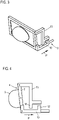
Fig. 1 in einer Seitenansicht, - Fig. 3
- die Anordnung aus
Fig. 1 in einer um die Horizontalachse verschwenkten Extrem- oder Anschlagstellung als Ausgangsposition vor der Vornahme der Grundeinstellung, - Fig. 4
- die entsprechende Seitenansicht,
- Fig. 5
- die Anordnung aus
Fig. 3 nach Durchführung der maximalen, insbesondere im Rahmen der Leuchtweitenregulierung erforderlichen Verschwenkung um die Horizontalachse und Kopplung der Mitnehmer der Stellelemente, - Fig. 6
- die entsprechende Seitenansicht hierzu,
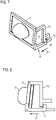
- Fig. 7
- die Anordnung aus
Fig. 5 mit um die Vertikalachse in die Sollposition erfolgter Verschwenkung des Trägers des Lichtmoduls, - Fig. 8
- die entsprechende Seitenansicht,
- Fig. 9
- die Rückstellung des Trägers um die Horizontalachse zur Einnahme der zweiten Sollposition bezüglich der Horizontalausrichtung und damit das in der Grundeinstellung befindliche ausgerichtete Lichtmodul,
- Fig. 10
- die Anordnung aus
Fig. 9 in einer Seitenansicht, - Fig. 11
- die Anordnung aus
Fig. 10 mit nach unten verschwenktem Lichtmodul zur Darstellung des maximalen Schwenkbereichs im Rahmen der Leuchtweitenregulierung, - Fig. 12
- die entsprechende Seitenansicht, und
- Fig. 13
- ein Diagramm zur Darstellung der Bewegungswege.
-
Fig. 1 zeigt einen erfindungsgemäßen Scheinwerfer 1 in Form einer reinen Prinzipdarstellung. Gestrichelt angedeutet ist ein Gehäuse 2 des Scheinwerfers, in dem ein hier ebenfalls nur prinzipiell dargestelltes Lichtmodul 3 aufgenommen ist. Das Lichtmodul 3 ist positionsfest an einem Träger 4 in Form eines Rahmens 5 verbaut. Der Rahmen 5 ist an einer Haltestruktur 6, die positionsfest am Gehäuse 2 angeordnet ist, um eine erste Gelenkverbindung 7, vorzugsweise ein Kugelgelenk, beweglich gelagert, so dass eine Verschwenkung um eine Horizontalachse y wie auch um eine Vertikalachse z möglich ist. - Vorgesehen ist des Weiteren eine Stellmechanik 8 sowie ein Aktuator 9, über den die Stellmechanik 8 bewegt werden kann, wobei über diese Stellmechanik 8 der Träger 4 respektive der Rahmen 5 im Raum verstellt werden kann, indem er in definierten Bewegungen um die horizontale Achse y und die vertikale Achse z verschwenkt werden kann.
- Die Stellmechanik 8 weist ein erstes Stellelement 10 auf, das mit dem Aktuator 9, einem Linearaktuator respektive einem Linearmotor, gekoppelt ist. Das erste Stellelement 10 ist linear beweglich, kann also, wie durch den Doppelpfeil P dargestellt, linear verschoben werden. Es ist mit dem Träger 4 respektive mit dem Rahmen 5 ebenfalls über eine Gelenkverbindung 11, bevorzugt wiederum ein Kugelgelenk, gelenkig verbunden, wobei die Gelenkverbindung 11 im Bereich der diagonal gegenüberliegenden Ecke des Rahmens 5 bezogen auf die Ecke, an der die Gelenkverbindung 7 vorgesehen ist, angeordnet ist.
- Am ersten Stellelement 10 ist ein erster Mitnehmerabschnitt 12 vorgesehen, der der mechanischen Kopplung zu einem zweiten Stellelement 13 dient, das ebenfalls Teil der Gelenkmechanik 8 ist. Das zweite Stellelement 13 ist über eine weitere Gelenkverbindung 14, vorzugsweise ebenfalls ein Kugelgelenk, am Rahmen 5 befestigt, und zwar im Bereich der rechten oberen Ecke auf gleicher Ebene respektive in der gleichen Horizontalebene wie die Gelenkverbindung 7, so dass die Gelenkverbindung 14 folglich in der Horizontalachse y verläuft respektive diese definiert. Das heißt, dass der Rahmen 5 um die zwischen den Gelenkverbindungen 7 und 14 definierte Horizontalachse y verschwenkt werden kann, was durch Bewegung des ersten Stellelements 10 erfolgt, wie nachfolgend beschrieben wird.
- Am zweien Stellelement 13 ist ein zweiter Mitnehmervorsprung 15 vorgesehen, der quasi in das U-förmige erste Stellelement 10 eingreift und ersichtlich im linearen Bewegungsweg des ersten Mitnehmerabschnitts 12 liegt. Die Mitnehmerabschnitte 12, 15 gehen eine temporäre mechanische Kopplung im Rahmen der Verstellbewegung ein, worauf nachfolgend noch eingegangen wird.
- Weiterhin ist, hier ebenfalls nur gestrichelt gezeigt, ein Arretiermittel 16, hier exemplarisch in Form einer Rastschiene 17 gezeigt, die mit einem Rastelement 18, was am zweiten Stellelement 13 vorgesehen ist, zusammenwirkt, um, worauf nachfolgend noch eingegangen wird, eine entsprechende Einstellposition des zweiten Stellelements 13 arretieren zu können.
- Weiterhin ist, ebenfalls nur gestrichelt angedeutet, ein weiterer Mitnehmerabschnitt 19 am ersten Stellelement 10 gezeigt, der optional ist, und der dazu dienen kann, das zweite Stellelement 13 bei Bedarf auch wieder zurückzubewegen, sollte die Sollposition im Rahmen der seitlichen Grundeinstellung, also Rechts-Links-Einstellung, versehentlich überfahren worden sein.
-
Fig. 2 zeigt in einer Seitenansicht die Anordnung ausFig. 1 , die für die nachfolgende Beschreibung als Ausgangsposition oder Ausgangslage angesehen wird. Es sei angenommen, dass in dieser Position der Träger 4 respektive Rahmen 5 quasi in einer Extremstellung ist, das heißt, dass er maximal um die Horizontalachse y verschwenkt ist, und bezogen auf die Vertikalachse z in einer Mittenposition ist beziehungsweise, bezogen auf die jeweiligen maximalen Schwenkwinkel, in der Extremposition um die z-Achse und einer Nullstellung um die y-Achse positioniert ist. Dies entspricht z. B. dem Anlieferungszustand des Scheinwerfers am Montageband. - Zur Durchführung der einmalig im Rahmen der Montage oder eines Scheinwerferaustausch vorzunehmenden Grundeinstellungspositionierung wird nun der Aktuator 9, also der Linearmotor über die in
Fig. 1 ebenfalls nur gestrichelt gezeigte Steuerungseinrichtung 20, die Teil des Scheinwerfers 1 sein kann, aber auch Teil des Kraftfahrzeugs, entsprechend angesteuert, so dass das erste Stellelement 10 in Richtung des Pfeils P' bewegt wird, das heißt, dass die beiden Mitnehmerabschnitte 12, 15 voneinander wegbewegt werden, wieFig. 3 und 4 zeigen. Da nur das erste Stellelement 10, nicht aber das zweite Stellelement 13 bewegt wird, bleibt folglich die y-Achse in ihrer räumlichen Position, es erfolgt lediglich eine Verschwenkung des Trägers 4 respektive des Rahmens 5 um die y-Achse. Dies führt dazu, dass das Lichtmodul 3 nach unten verschwenkt wird, wie dieFiguren 3 und insbesondere 4 deutlich zeigen. Es sei angenommen, dass eine Verschwenkung ausgehend von der Nullstellung gemäßFig. 1 um 5° nach unten erfolgt. In dieser Position sei angenommen, dass eine Extrem- oder Anschlagposition in Bezug auf den maximalen Schwenkweg um die Horizontalachse y eingenommen ist. Die eingenommenen Positions- oder Steuerdaten werden gegebenenfalls seitens der Steuerungseinrichtung 20 erfasst und gespeichert. Die Ausrichtung des Rahmens 5 um die Vertikalachse z hat sich durch diese Stellbewegung nicht geändert, das heißt, dass sich der Rahmen 5 und damit auch das zweite Stellelement 13 nach wie vor in der einen seitlichen Anschlagposition, also in einer maximalen seitlichen Verschwenkstellung um die Vertikalachse z befindet. - Im nächsten Schritt, siehe die
Figuren 5 und 6 , wird das erste Stellelement 10 über den Aktuator 9 wieder in die entgegengesetzte Richtung, wie durch den Pfeil P" dargestellt, bewegt. Hierbei kommt es, wie insbesondereFig. 6 deutlich zeigt, zu einem erneuten Verschwenken des Rahmens 5 um die horizontale y-Achse, das heißt, dass das Lichtmodul 3 nach oben geschwenkt wird. Während dieser Verstellbewegung bleibt zumindest bis zu dem Zeitpunkt, zu dem der erste Mitnehmerabschnitt 12 gegen den zweiten Mitnehmerabschnitt 15 läuft, die y-Achse positionsfest, es erfolgt lediglich eine Verschwenkung des Trägers 5 um die y-Achse, beispielsweise in diesem Fall um 5° nach oben, das heißt, dass der maximale Verschwenkwinkel oben-unten, der auch im Rahmen der Lichweitenregulierung durchlaufen werden kann, insgesamt 10° beträgt. - Wie
Fig. 6 zeigt, berühren während der Linearbewegung des ersten Stellelements 10 entlang seiner nicht näher gezeigten Linearführung in Richtung des Pfeils P" die beiden Mitnehmerabschnitte 12 und 15 einander. Wird diese Bewegung fortgesetzt, wie dieFiguren 7 und 8 zeigen, so wird infolge dieser mechanischen Mitnehmerkopplung auch das zweite Stellelement 13 bewegt, es wird entlang seiner ebenfalls nicht näher gezeigten Linearführung verschoben. Hierbei kommt es zu einer Verschwenkung des Rahmens 5 um die vertikale z-Achse, nachdem nunmehr die gesamte Gelenkmechanik 8 linear verschoben wird und auch die y-Achse hierüber quasi mitgenommen wird und um die z-Achse verschwenkt wird. Die eingenommene Schwenkstellung um die horizontale y-Achse bleibt während dieser fortgesetzten Bewegung unverändert, da sich wie beschrieben die y-Achse mit im Raum bewegt. Es erfolgt also ab dem Zeitpunkt der Mitnehmerkopplung die Seiteneinstellung durch Verschwenken um die vertikale z-Achse ausgehend von der vormals eingenommenen Extrem- oder Anschlagposition in Bezug auf diesen maximalen Verschwenkwinkel um die z-Achse. - Diese Bewegung wird solange durchgeführt, bis die messtechnisch erfasste Sollposition in Bezug auf die Seiteneinstellung, also Rechts-Links-Einstellung, erreicht ist. Es sei angenommen, dass diese Sollposition nach einem Verschwenkwinkel um die z-Achse von 5° erreicht ist. In dieser Position ist ersichtlich der Träger 5 und damit das Lichtmodul 3 nicht nur um die y-Achse, sondern auch um die z-Achse verschwenkt, wie
Fig. 8 anschaulich zeigt. Die eingenommene Position wird gegebenenfalls mit entsprechenden Positionsdaten seitens der Steuerungseinrichtung 20 wiederum erfasst. Der Einstellvorgang zur Rechts-Links-Seitenausrichtung ist damit abgeschlossen. - Wie beschrieben befindet sich der Träger 5 in Bezug auf die Verschwenkung um die horizontale y-Achse wiederum in einer Extrem- oder Anschlagposition, das heißt, er ist maximal nach oben verschwenkt. Nachdem die Seitenausrichtung um die z-Achse erfolgt ist, muss im nächsten Schritt die Ausrichtung um die y-Achse, also die Oben-Unten-Ausrichtung erfolgen. Hierzu wird, siehe die
Figuren 9 und 10 , das erste Stellelement 10 über den Aktuator 9 wieder in die entgegengesetzte Richtung, wie durch den Pfeil P'" gezeigt ist, wieder zurückbewegt, das heißt, dass die beiden Mitnehmerabschnitte 12, 15 wieder voneinander getrennt werden. Die beiden Stellelemente 10 und 13 werden folglich voneinander gekoppelt. Die Position des zweiten Stellelements 13 ist jedoch fixiert, nachdem in der gemäß derFiguren 7, 8 eingenommenen Sollposition die Positionsarretierung über das Arretiermittel 16 erfolgt ist. Das heißt, dass die Seitenausrichtung nicht mehr geändert wird. - Die Bewegung des ersten Stellelements 10 in Richtung des Pfeils P'" führt zu einem erneuten Verschwenken des Rahmens 5 nach unten, wobei diese Schwenkbewegung solange erfolgt, bis auch bezüglich der y-Achse und damit der Oben-Unten-Ausrichtung die messtechnisch erfasste Sollposition erreicht ist. Es sei angenommen, dass diese beispielsweise bei 0° erreicht ist, wie in den
Figuren 9 und 10 gezeigt ist. Diese Sollposition wird ebenfalls seitens der Steuerungseinrichtung 20 erfasst und gespeichert und als Ausgangsposition für eine erforderliche Leuchtweitenregulierung verwendet. Das heißt, dass ausgehend aus dieser Sollposition heraus im Falle einer entsprechend zu verändernden Vorfeldausleuchtung der Rahmen 5 samt Lichtmodul 3 über den Aktuator 9 durch Verschieben des ersten Stellelements 10 geringfügig auf- oder abgeschwenkt wird, je nach erforderlicher Regulierungsweise. - Die
Figuren 11 und 12 zeigen schließlich die Anordnung ausFig. 9, 10 , bei der das erste Stellelement 10 über den Aktuator 9 noch weiter in Richtung des Pfeils P‴ bewegt wurde, das heißt, dass das Lichtmodul 3 und der Träger 5 noch weiter nach unten geschwenkt wurden, um den maximalen Verschwenkweg im Rahmen der Leuchtweitenregulierung darzustellen. Dieser beträgt exemplarisch 10°, und wird über den maximalen Bewegungsweg des ersten Stellelements 10 zwischen der in denFiguren 11 und 12 gezeigten einen Extremstellung und der in denFiguren 5 und 6 gezeigten Extremstellung, in der die beiden Anschlagelemente 12 und 15 aneinander anliegen definiert ist. -
Figur 13 zeigt schließlich ein Diagramm in Bezug auf die Einstellwege. Längs der Abszisse ist in den beiden Diagrammen a und b jeweils der Verfahrweg des Aktuators 9 dargestellt, längs der Ordinate im Falle des Diagramms a die vertikale Position der Hell-Dunkel-Grenze des Lichtmoduls 3, also die Verschwenkung des Lichtmoduls 3 um die y-Achse, und im Diagramm b die horizontale Position der Hell-Dunkel-Grenze, also die Seitenausrichtung und damit die Verschwenkung um die z-Achse. - Mit Min. und Max. in Bezug auf die Abszisse ist jeweils der maximale Aktuatorweg angegeben, bei Min. befindet sich der Aktuator in der Position gemäß
Fig. 3/4 , bei Max. in der Position, in der er den maximalen Bewegungsweg durchlaufen hat. In Bezug auf die Ordinate bedeutet im Diagramm a die Bezeichnung Min. und Max. die jeweilige Extremposition, einmal vollständig nach unten geschwenkt, einmal vollständig nach oben geschwenkt. In Bezug auf das Diagramm b bedeutet in Bezug auf die Ordinate die Bezeichnungen Min. und Max. die jeweiligen Extrempositionen, also die Verschwenkung maximal zur rechten und zur linken Seite. - Ausgehend von einem Verfahrweg des Aktuators aus der Min-Stellung findet, siehe Diagramm a, ein Verschwenken des Rahmens 5 und damit des Lichtmoduls 3 ausschließlich um die Horizontalachse statt, das heißt, dass die Hell-Dunkel-Grenze von unten nach oben wandert. Dies gilt solange, bis an der Position x die beiden Mitnehmerabschnitte 12 und 15 koppeln. Bis zu diesem Zeitpunkt verblieb die horizontale Position der Hell-Dunkel-Grenze, also die Seitenausrichtung des Rahmens 5, unangetastet, sie befand sich in der einen Extremposition, war also beispielsweise vollkommen nach rechts verschwenkt. Mit der Kopplung zum Zeitpunkt beziehungsweise zur Verfahrwegsposition x setzt dann aber die Verschwenkung um die z-Achse ein, während gleichzeitig die Verschwenkung um die y-Achse beendet ist. Der Rahmen 5 ist von der einen Extremposition in die andere Extremposition um die y-Achse verschwenkt, in dieser verbleibt er während der restlichen Aktuatorbewegung. Während dieser findet lediglich eine Verschwenkung um die vertikale z-Achse von der einen in die andere Maximalposition statt.
- Wie
Fig. 13 zeigt, findet die Verstellung um die z-Achse nur in ca. einem Viertel des maximalen Aktuatorverfahrweges statt. Das heißt, dass dreiviertel des maximalen Aktuatorweges für die Vornahme der Leuchtweitenregulierung zur Verfügung stehen.
Claims (16)
- Scheinwerfer für ein Kraftfahrzeug, umfassend ein in einem Gehäuse (2) beweglich gelagertes Lichtmodul (3) sowie Stellmittel zum Einstellen der räumlichen Position des Lichtmoduls (3) im Gehäuse (2), wobei das Lichtmodul (3) an einem um eine horizontale und eine vertikale Achse (y, z) verschwenkbaren Träger (4) angeordnet ist, welcher Träger (4) mit dem Stellmittel umfassend eine Stellmechanik (8) und einen die Stellmechanik (8) bewegenden Aktuator (9) gekoppelt ist, wobei die Stellmechanik (8) derart ausgebildet ist, dass bei Betrieb des Aktuators (9) eine separate Verschwenkung des Trägers (4) sowohl um die horizontale als auch um die vertikale Achse (y, z) erfolgt, dadurch gekennzeichnet, dass die Stellmechanik (8) ein erstes und ein zweites, jeweils mit dem Träger (4) gekoppeltes bewegbares Stellelement (10, 13) aufweist, wobei der Träger (4) über das erste Stellelement (10) um die horizontale Achse (y) und über das zweite Stellelement (13) um die vertikale Achse (z) verschwenkbar ist und von denen das erste Stellelement (10) über den Aktuator (9) zum Verschwenken um eine Achse (y) bewegbar ist und während der Bewegung temporär mit dem zweiten Stellelement (13) zum Verschwenken um die andere Achse (z) in Wirkungsverbindung bringbar ist.
- Scheinwerfer nach Anspruch 1, dadurch gekennzeichnet, dass der Aktuator (9) mit dem ersten, die Verschwenkung um die horizontal Achse (y) erwirkenden Stellelement (10) gekoppelt ist.
- Scheinwerfer nach Anspruch 1 oder 2, dadurch gekennzeichnet, dass der Träger (4) als Rahmen (5), an oder in dem das Lichtmodul (3) positionsfest fixiert ist, ausgeführt ist, welcher Rahmen (5) im Bereich einer Ecke oder einer Vertikalseite an einer Haltestruktur (6) gelagert ist, und dass das erste und das zweite Stellelement (10, 13) an der gegenüberliegenden Seite des Rahmens (5) im Bereich der unteren und oberen Ecken gelagert sind.
- Scheinwerfer nach Anspruch 3, dadurch gekennzeichnet, dass das erste Stellelement (10) im Bereich der der Ecke, an der der Träger (5) gelagert ist, diagonal gegenüber liegenden Ecke gelagert ist, während das zweite Stellelement (13) im Bereich der anderen Ecke im wesentlichen auf gleicher Höhe wie der Träger (4) gelagert ist.
- Scheinwerfer nach einem der vorangehenden Ansprüche, dadurch gekennzeichnet, dass der Träger (4) an einer Haltestruktur (6) und die Stellelemente (10, 13) am Träger (4) über Kugelgelenke oder Kardangelenke gelagert sind.
- Scheinwerfer nach einem der vorangehenden Ansprüche, dadurch gekennzeichnet, dass das erste und das zweite Stellelement (10, 13) jeweils linear bewegbar gelagert ist und der Aktuator (9) ein Linearaktuator ist.
- Scheinwerfer nach einem der vorangehenden Ansprüche, dadurch gekennzeichnet, dass der Aktuator (9) gleichzeitig als Aktuator (9) für eine Leuchtweitenregelung, im Rahmen welcher der Träger (4) um die horizontale Achse (y) verschwenkt wird, dient.
- Scheinwerfer nach einem der vorangehenden Ansprüche, dadurch gekennzeichnet, dass das erste und das zweite Stellelement (10, 13) jeweils einen Mitnehmerabschnitt (12, 15) aufweisen, wobei der Mitnehmerabschnitt (12) des über den Aktuator (9) bewegbaren Stellelements (10) während der Bewegung mit dem Mitnehmerabschnitt (15) des anderen Stellelements (13) in lösbare Wirkungsverbindung tritt.
- Scheinwerfer nach Anspruch 8, dadurch gekennzeichnet, dass am ersten oder am zweiten Stellelement (10, 13) zwei Mitnehmerabschnitte (12, 19) vorgesehen sind, wobei bei einer Bewegung des mit dem Aktuator (9) gekoppelten Stellelements (10) in eine erste Richtung der eine Mitnehmerabschnitt (12) mit dem Mitnehmerabschnitt (15) des anderen Stellelements (13) in Wirkungsverbindung tritt, und bei einer Bewegung in die entgegengesetzte Richtung der andere Mitnehmerabschnitt (19) mit dem Mitnehmerabschnitt (15) es anderen Stellelements (13) in Wirkungsverbindung tritt.
- Scheinwerfer nach einem der vorangehenden Ansprüche, dadurch gekennzeichnet, dass Arretiermittel (16) zum Arretieren der Stellmechanik (8) derart, dass die Verschwenkung des Trägers (8) um die vertikale Achse (z) gesperrt ist, vorgesehen sind.
- Scheinwerfer nach Anspruch 10, dadurch gekennzeichnet, dass das Arretiermittel (16) ein Rastmittel ist, über das die Verschwenkungstellung des die Verschwenkung um die vertikale Achse (z) erwirkende Stellelements (13) automatisch arretiert.
- Scheinwerfer nach Anspruch 11, dadurch gekennzeichnet, dass das Rastmittel (16) eine Rastschiene (17), längs welcher das Stellelement (13) bewegbar ist, und einen am Stellelement (13) vorgesehenen Rastabschnitt (18), der mit der Rastschiene (17) zusammenwirkt, umfasst.
- Scheinwerfer nach Anspruch 10, dadurch gekennzeichnet, dass das Arretiermittel (16) ein manuell zu setzendes Arretierelement ist.
- Scheinwerfer nach einem der vorangehenden Ansprüche, umfassend eine Steuerungseinrichtung (20) zum Ansteuern des Aktuators (9) und zum Erfassen von Positionsinformationen zum Träger (4) und/oder zum ersten und/oder zweiten Stellelement (10, 13).
- Kraftfahrzeug, umfassend wenigstens einen Scheinwerfer (1) nach einem der vorangehenden Ansprüche.
- Verfahren zum Einstellen eines Scheinwerfers nach einem der Ansprüche 1 bis 14, verbaut in einem Kraftfahrzeugs, bei welchem Verfahren das erste Stellelement (10) bei in einer um die vertikale Achse (z) in eine Endposition verschwenktem Träger (4) über den Aktuator (9) bewegt wird, bis durch Interaktion des ersten Stellelements (10) mit dem zweiten Stellelement (13) der Träger (4) um die vertikale Achse (z) in eine erste Sollposition verschwenkt ist, in welcher das zweite Stellelement (13) arretiert wird, wonach das erste Stellelement (10) über den Aktuator (9) unter Verschwenkung um die horizontale Achse (y) zurück bewegt wird, bis der Träger (4) eine zweite Sollposition erreicht hat, wobei die Positionsinformationen des Trägers (4) und/oder des ersten und/oder der zweiten Stellelements (10, 13) zu den beiden Sollpositionen in einer Steuerungseinrichtung (20) gespeichert werden.
Applications Claiming Priority (1)
| Application Number | Priority Date | Filing Date | Title |
|---|---|---|---|
| DE102018212500.7A DE102018212500A1 (de) | 2018-07-26 | 2018-07-26 | Scheinwerfer für ein Kraftfahrzeug |
Publications (2)
| Publication Number | Publication Date |
|---|---|
| EP3599131A1 EP3599131A1 (de) | 2020-01-29 |
| EP3599131B1 true EP3599131B1 (de) | 2022-05-04 |
Family
ID=66998223
Family Applications (1)
| Application Number | Title | Priority Date | Filing Date |
|---|---|---|---|
| EP19181032.4A Active EP3599131B1 (de) | 2018-07-26 | 2019-06-18 | Scheinwerfer für ein kraftfahrzeug |
Country Status (2)
| Country | Link |
|---|---|
| EP (1) | EP3599131B1 (de) |
| DE (1) | DE102018212500A1 (de) |
Family Cites Families (4)
| Publication number | Priority date | Publication date | Assignee | Title |
|---|---|---|---|---|
| FR2636578B1 (fr) * | 1988-09-22 | 1993-06-18 | Valeo Vision | Dispositif de reglage d'orientation pour projecteur de vehicule automobile |
| FR2826709B1 (fr) * | 2001-06-29 | 2004-02-13 | Valeo Vision | Dispositif d'eclairage a orientation variable |
| JP4190004B2 (ja) * | 2003-12-25 | 2008-12-03 | 株式会社小糸製作所 | 車輌用灯具 |
| DE202011003404U1 (de) * | 2011-03-01 | 2011-05-12 | Automotive Lighting Reutlingen Gmbh | Scheinwerfer eines Kraftfahrzeugs |
-
2018
- 2018-07-26 DE DE102018212500.7A patent/DE102018212500A1/de not_active Withdrawn
-
2019
- 2019-06-18 EP EP19181032.4A patent/EP3599131B1/de active Active
Also Published As
| Publication number | Publication date |
|---|---|
| EP3599131A1 (de) | 2020-01-29 |
| DE102018212500A1 (de) | 2020-01-30 |
Similar Documents
| Publication | Publication Date | Title |
|---|---|---|
| DE60207497T2 (de) | Vorrichtung und Verfahren zur Befestigung eines Teiles am Fahrgestell | |
| DE102010013522B4 (de) | Verstellbare Lenkvorrichtung mit mechanischer Speicherung | |
| DE102013109097B3 (de) | Anordnung für ein Fahrzeugdach mit einem Deckel | |
| AT516100B1 (de) | Einstellsystem für einen Fahrzeugscheinwerfer sowie Fahrzeugscheinwerfer | |
| DE102014109698B3 (de) | Anordnung mit einem Deckel für ein Fahrzeugdach | |
| DE102015101747A1 (de) | Anordnung mit einem Deckel für ein Fahrzeugdach | |
| EP3142881A1 (de) | Anordnung mit einem deckel für ein fahrzeugdach | |
| EP2862757A1 (de) | Verstellvorrichtung für eine Frontklappe und zugehöriges Kraftfahrzeug | |
| DE102004051175A1 (de) | Fernlicht-/Abblendlicht-Stellarm-Baueinheit | |
| DE10133436A1 (de) | Modul, insbesondere Schiebedachmodul für ein Fahrzeug | |
| DE102013109099B3 (de) | Anordnungen für ein Fahrzeugdach mit einem Deckel | |
| EP3599131B1 (de) | Scheinwerfer für ein kraftfahrzeug | |
| DE102009016399B4 (de) | Öffnungsvorrichtung für Schwenkschiebetüren | |
| WO2001049447A1 (de) | Anlage zur herstellung von fahrwegelementen | |
| EP1810561B1 (de) | Zugvorrichtung | |
| DE102014111539B4 (de) | Anordnung mit einem Deckel für ein Fahrzeugdach | |
| DE202007003080U1 (de) | Führungsmechanik für einen Deckel eines Schiebehebedaches eines Fahrzeugs | |
| DE10141845A1 (de) | Schiebedachsystem | |
| DE102021118688A1 (de) | Selbstfahrende bodenfräsmaschine, adapterset für eine bodenfräsmaschine sowie verfahren zum inkrementellen verschieben und/oder vergrössern des hubbereiches | |
| EP0133637A1 (de) | Frontseitige Geräteanbauvorrichtung für ein frontverkleidetes land- und/oder bauwirtschaftlich nutzbares Kraftfahrzeug, insbesondere Ackerschlepper | |
| WO2020193088A1 (de) | Variables mitnehmersystem | |
| DE102019131595A1 (de) | Fahrzeugsitz | |
| DE102023114147A1 (de) | Gleitschalungsfertiger | |
| DE102004058991A1 (de) | Luftleitvorrichtung für ein Cabriolet-Fahrzeug | |
| EP1747338B1 (de) | Scharnierbeschlag für eine kfz-tür |
Legal Events
| Date | Code | Title | Description |
|---|---|---|---|
| PUAI | Public reference made under article 153(3) epc to a published international application that has entered the european phase |
Free format text: ORIGINAL CODE: 0009012 |
|
| STAA | Information on the status of an ep patent application or granted ep patent |
Free format text: STATUS: THE APPLICATION HAS BEEN PUBLISHED |
|
| AK | Designated contracting states |
Kind code of ref document: A1 Designated state(s): AL AT BE BG CH CY CZ DE DK EE ES FI FR GB GR HR HU IE IS IT LI LT LU LV MC MK MT NL NO PL PT RO RS SE SI SK SM TR |
|
| AX | Request for extension of the european patent |
Extension state: BA ME |
|
| STAA | Information on the status of an ep patent application or granted ep patent |
Free format text: STATUS: REQUEST FOR EXAMINATION WAS MADE |
|
| 17P | Request for examination filed |
Effective date: 20200729 |
|
| RBV | Designated contracting states (corrected) |
Designated state(s): AL AT BE BG CH CY CZ DE DK EE ES FI FR GB GR HR HU IE IS IT LI LT LU LV MC MK MT NL NO PL PT RO RS SE SI SK SM TR |
|
| GRAP | Despatch of communication of intention to grant a patent |
Free format text: ORIGINAL CODE: EPIDOSNIGR1 |
|
| STAA | Information on the status of an ep patent application or granted ep patent |
Free format text: STATUS: GRANT OF PATENT IS INTENDED |
|
| INTG | Intention to grant announced |
Effective date: 20220118 |
|
| GRAS | Grant fee paid |
Free format text: ORIGINAL CODE: EPIDOSNIGR3 |
|
| GRAA | (expected) grant |
Free format text: ORIGINAL CODE: 0009210 |
|
| STAA | Information on the status of an ep patent application or granted ep patent |
Free format text: STATUS: THE PATENT HAS BEEN GRANTED |
|
| AK | Designated contracting states |
Kind code of ref document: B1 Designated state(s): AL AT BE BG CH CY CZ DE DK EE ES FI FR GB GR HR HU IE IS IT LI LT LU LV MC MK MT NL NO PL PT RO RS SE SI SK SM TR |
|
| REG | Reference to a national code |
Ref country code: GB Ref legal event code: FG4D Free format text: NOT ENGLISH |
|
| REG | Reference to a national code |
Ref country code: CH Ref legal event code: EP |
|
| REG | Reference to a national code |
Ref country code: AT Ref legal event code: REF Ref document number: 1488722 Country of ref document: AT Kind code of ref document: T Effective date: 20220515 |
|
| REG | Reference to a national code |
Ref country code: IE Ref legal event code: FG4D Free format text: LANGUAGE OF EP DOCUMENT: GERMAN Ref country code: DE Ref legal event code: R096 Ref document number: 502019004247 Country of ref document: DE |
|
| REG | Reference to a national code |
Ref country code: LT Ref legal event code: MG9D |
|
| REG | Reference to a national code |
Ref country code: NL Ref legal event code: MP Effective date: 20220504 |
|
| PG25 | Lapsed in a contracting state [announced via postgrant information from national office to epo] |
Ref country code: SE Free format text: LAPSE BECAUSE OF FAILURE TO SUBMIT A TRANSLATION OF THE DESCRIPTION OR TO PAY THE FEE WITHIN THE PRESCRIBED TIME-LIMIT Effective date: 20220504 Ref country code: PT Free format text: LAPSE BECAUSE OF FAILURE TO SUBMIT A TRANSLATION OF THE DESCRIPTION OR TO PAY THE FEE WITHIN THE PRESCRIBED TIME-LIMIT Effective date: 20220905 Ref country code: NO Free format text: LAPSE BECAUSE OF FAILURE TO SUBMIT A TRANSLATION OF THE DESCRIPTION OR TO PAY THE FEE WITHIN THE PRESCRIBED TIME-LIMIT Effective date: 20220804 Ref country code: NL Free format text: LAPSE BECAUSE OF FAILURE TO SUBMIT A TRANSLATION OF THE DESCRIPTION OR TO PAY THE FEE WITHIN THE PRESCRIBED TIME-LIMIT Effective date: 20220504 Ref country code: LT Free format text: LAPSE BECAUSE OF FAILURE TO SUBMIT A TRANSLATION OF THE DESCRIPTION OR TO PAY THE FEE WITHIN THE PRESCRIBED TIME-LIMIT Effective date: 20220504 Ref country code: HR Free format text: LAPSE BECAUSE OF FAILURE TO SUBMIT A TRANSLATION OF THE DESCRIPTION OR TO PAY THE FEE WITHIN THE PRESCRIBED TIME-LIMIT Effective date: 20220504 Ref country code: GR Free format text: LAPSE BECAUSE OF FAILURE TO SUBMIT A TRANSLATION OF THE DESCRIPTION OR TO PAY THE FEE WITHIN THE PRESCRIBED TIME-LIMIT Effective date: 20220805 Ref country code: FI Free format text: LAPSE BECAUSE OF FAILURE TO SUBMIT A TRANSLATION OF THE DESCRIPTION OR TO PAY THE FEE WITHIN THE PRESCRIBED TIME-LIMIT Effective date: 20220504 Ref country code: ES Free format text: LAPSE BECAUSE OF FAILURE TO SUBMIT A TRANSLATION OF THE DESCRIPTION OR TO PAY THE FEE WITHIN THE PRESCRIBED TIME-LIMIT Effective date: 20220504 Ref country code: BG Free format text: LAPSE BECAUSE OF FAILURE TO SUBMIT A TRANSLATION OF THE DESCRIPTION OR TO PAY THE FEE WITHIN THE PRESCRIBED TIME-LIMIT Effective date: 20220804 |
|
| PG25 | Lapsed in a contracting state [announced via postgrant information from national office to epo] |
Ref country code: RS Free format text: LAPSE BECAUSE OF FAILURE TO SUBMIT A TRANSLATION OF THE DESCRIPTION OR TO PAY THE FEE WITHIN THE PRESCRIBED TIME-LIMIT Effective date: 20220504 Ref country code: PL Free format text: LAPSE BECAUSE OF FAILURE TO SUBMIT A TRANSLATION OF THE DESCRIPTION OR TO PAY THE FEE WITHIN THE PRESCRIBED TIME-LIMIT Effective date: 20220504 Ref country code: LV Free format text: LAPSE BECAUSE OF FAILURE TO SUBMIT A TRANSLATION OF THE DESCRIPTION OR TO PAY THE FEE WITHIN THE PRESCRIBED TIME-LIMIT Effective date: 20220504 Ref country code: IS Free format text: LAPSE BECAUSE OF FAILURE TO SUBMIT A TRANSLATION OF THE DESCRIPTION OR TO PAY THE FEE WITHIN THE PRESCRIBED TIME-LIMIT Effective date: 20220904 |
|
| PG25 | Lapsed in a contracting state [announced via postgrant information from national office to epo] |
Ref country code: SM Free format text: LAPSE BECAUSE OF FAILURE TO SUBMIT A TRANSLATION OF THE DESCRIPTION OR TO PAY THE FEE WITHIN THE PRESCRIBED TIME-LIMIT Effective date: 20220504 Ref country code: SK Free format text: LAPSE BECAUSE OF FAILURE TO SUBMIT A TRANSLATION OF THE DESCRIPTION OR TO PAY THE FEE WITHIN THE PRESCRIBED TIME-LIMIT Effective date: 20220504 Ref country code: RO Free format text: LAPSE BECAUSE OF FAILURE TO SUBMIT A TRANSLATION OF THE DESCRIPTION OR TO PAY THE FEE WITHIN THE PRESCRIBED TIME-LIMIT Effective date: 20220504 Ref country code: EE Free format text: LAPSE BECAUSE OF FAILURE TO SUBMIT A TRANSLATION OF THE DESCRIPTION OR TO PAY THE FEE WITHIN THE PRESCRIBED TIME-LIMIT Effective date: 20220504 Ref country code: DK Free format text: LAPSE BECAUSE OF FAILURE TO SUBMIT A TRANSLATION OF THE DESCRIPTION OR TO PAY THE FEE WITHIN THE PRESCRIBED TIME-LIMIT Effective date: 20220504 Ref country code: CZ Free format text: LAPSE BECAUSE OF FAILURE TO SUBMIT A TRANSLATION OF THE DESCRIPTION OR TO PAY THE FEE WITHIN THE PRESCRIBED TIME-LIMIT Effective date: 20220504 |
|
| REG | Reference to a national code |
Ref country code: CH Ref legal event code: PL |
|
| REG | Reference to a national code |
Ref country code: DE Ref legal event code: R097 Ref document number: 502019004247 Country of ref document: DE |
|
| REG | Reference to a national code |
Ref country code: BE Ref legal event code: MM Effective date: 20220630 |
|
| PG25 | Lapsed in a contracting state [announced via postgrant information from national office to epo] |
Ref country code: MC Free format text: LAPSE BECAUSE OF FAILURE TO SUBMIT A TRANSLATION OF THE DESCRIPTION OR TO PAY THE FEE WITHIN THE PRESCRIBED TIME-LIMIT Effective date: 20220504 |
|
| PLBE | No opposition filed within time limit |
Free format text: ORIGINAL CODE: 0009261 |
|
| STAA | Information on the status of an ep patent application or granted ep patent |
Free format text: STATUS: NO OPPOSITION FILED WITHIN TIME LIMIT |
|
| PG25 | Lapsed in a contracting state [announced via postgrant information from national office to epo] |
Ref country code: AL Free format text: LAPSE BECAUSE OF FAILURE TO SUBMIT A TRANSLATION OF THE DESCRIPTION OR TO PAY THE FEE WITHIN THE PRESCRIBED TIME-LIMIT Effective date: 20220504 |
|
| 26N | No opposition filed |
Effective date: 20230207 |
|
| PG25 | Lapsed in a contracting state [announced via postgrant information from national office to epo] |
Ref country code: LU Free format text: LAPSE BECAUSE OF NON-PAYMENT OF DUE FEES Effective date: 20220618 Ref country code: LI Free format text: LAPSE BECAUSE OF NON-PAYMENT OF DUE FEES Effective date: 20220630 Ref country code: IE Free format text: LAPSE BECAUSE OF NON-PAYMENT OF DUE FEES Effective date: 20220618 Ref country code: CH Free format text: LAPSE BECAUSE OF NON-PAYMENT OF DUE FEES Effective date: 20220630 |
|
| PG25 | Lapsed in a contracting state [announced via postgrant information from national office to epo] |
Ref country code: SI Free format text: LAPSE BECAUSE OF FAILURE TO SUBMIT A TRANSLATION OF THE DESCRIPTION OR TO PAY THE FEE WITHIN THE PRESCRIBED TIME-LIMIT Effective date: 20220504 Ref country code: BE Free format text: LAPSE BECAUSE OF NON-PAYMENT OF DUE FEES Effective date: 20220630 |
|
| P01 | Opt-out of the competence of the unified patent court (upc) registered |
Effective date: 20230530 |
|
| PG25 | Lapsed in a contracting state [announced via postgrant information from national office to epo] |
Ref country code: IT Free format text: LAPSE BECAUSE OF FAILURE TO SUBMIT A TRANSLATION OF THE DESCRIPTION OR TO PAY THE FEE WITHIN THE PRESCRIBED TIME-LIMIT Effective date: 20220504 |
|
| PG25 | Lapsed in a contracting state [announced via postgrant information from national office to epo] |
Ref country code: MK Free format text: LAPSE BECAUSE OF FAILURE TO SUBMIT A TRANSLATION OF THE DESCRIPTION OR TO PAY THE FEE WITHIN THE PRESCRIBED TIME-LIMIT Effective date: 20220504 Ref country code: CY Free format text: LAPSE BECAUSE OF FAILURE TO SUBMIT A TRANSLATION OF THE DESCRIPTION OR TO PAY THE FEE WITHIN THE PRESCRIBED TIME-LIMIT Effective date: 20220504 |
|
| PG25 | Lapsed in a contracting state [announced via postgrant information from national office to epo] |
Ref country code: HU Free format text: LAPSE BECAUSE OF FAILURE TO SUBMIT A TRANSLATION OF THE DESCRIPTION OR TO PAY THE FEE WITHIN THE PRESCRIBED TIME-LIMIT; INVALID AB INITIO Effective date: 20190618 |
|
| PG25 | Lapsed in a contracting state [announced via postgrant information from national office to epo] |
Ref country code: MT Free format text: LAPSE BECAUSE OF FAILURE TO SUBMIT A TRANSLATION OF THE DESCRIPTION OR TO PAY THE FEE WITHIN THE PRESCRIBED TIME-LIMIT Effective date: 20220504 |
|
| PG25 | Lapsed in a contracting state [announced via postgrant information from national office to epo] |
Ref country code: BG Free format text: LAPSE BECAUSE OF FAILURE TO SUBMIT A TRANSLATION OF THE DESCRIPTION OR TO PAY THE FEE WITHIN THE PRESCRIBED TIME-LIMIT Effective date: 20220504 |
|
| PG25 | Lapsed in a contracting state [announced via postgrant information from national office to epo] |
Ref country code: BG Free format text: LAPSE BECAUSE OF FAILURE TO SUBMIT A TRANSLATION OF THE DESCRIPTION OR TO PAY THE FEE WITHIN THE PRESCRIBED TIME-LIMIT Effective date: 20220504 |
|
| PGFP | Annual fee paid to national office [announced via postgrant information from national office to epo] |
Ref country code: DE Payment date: 20250630 Year of fee payment: 7 |
|
| PGFP | Annual fee paid to national office [announced via postgrant information from national office to epo] |
Ref country code: GB Payment date: 20250621 Year of fee payment: 7 |
|
| PGFP | Annual fee paid to national office [announced via postgrant information from national office to epo] |
Ref country code: FR Payment date: 20250617 Year of fee payment: 7 |
|
| REG | Reference to a national code |
Ref country code: AT Ref legal event code: MM01 Ref document number: 1488722 Country of ref document: AT Kind code of ref document: T Effective date: 20240618 |
|
| PG25 | Lapsed in a contracting state [announced via postgrant information from national office to epo] |
Ref country code: AT Free format text: LAPSE BECAUSE OF NON-PAYMENT OF DUE FEES Effective date: 20240618 |
|
| PG25 | Lapsed in a contracting state [announced via postgrant information from national office to epo] |
Ref country code: TR Free format text: LAPSE BECAUSE OF FAILURE TO SUBMIT A TRANSLATION OF THE DESCRIPTION OR TO PAY THE FEE WITHIN THE PRESCRIBED TIME-LIMIT Effective date: 20220504 |
|
| PGFP | Annual fee paid to national office [announced via postgrant information from national office to epo] |
Ref country code: AT Payment date: 20260410 Year of fee payment: 5 |