EP3597903B1 - Système de lacet pour éolienne - Google Patents
Système de lacet pour éolienne Download PDFInfo
- Publication number
- EP3597903B1 EP3597903B1 EP18382549.6A EP18382549A EP3597903B1 EP 3597903 B1 EP3597903 B1 EP 3597903B1 EP 18382549 A EP18382549 A EP 18382549A EP 3597903 B1 EP3597903 B1 EP 3597903B1
- Authority
- EP
- European Patent Office
- Prior art keywords
- gliding
- yaw
- bearing
- tower
- braking
- Prior art date
- Legal status (The legal status is an assumption and is not a legal conclusion. Google has not performed a legal analysis and makes no representation as to the accuracy of the status listed.)
- Active
Links
- 238000005461 lubrication Methods 0.000 description 8
- 230000000903 blocking effect Effects 0.000 description 3
- 239000004519 grease Substances 0.000 description 3
- 238000000034 method Methods 0.000 description 3
- 238000011109 contamination Methods 0.000 description 2
- 230000005611 electricity Effects 0.000 description 2
- 230000007246 mechanism Effects 0.000 description 2
- 230000009471 action Effects 0.000 description 1
- 230000004913 activation Effects 0.000 description 1
- 238000005266 casting Methods 0.000 description 1
- 230000008878 coupling Effects 0.000 description 1
- 238000010168 coupling process Methods 0.000 description 1
- 238000005859 coupling reaction Methods 0.000 description 1
- 230000009849 deactivation Effects 0.000 description 1
- 230000007423 decrease Effects 0.000 description 1
- 230000000694 effects Effects 0.000 description 1
- 238000005516 engineering process Methods 0.000 description 1
- 238000005304 joining Methods 0.000 description 1
- 238000012423 maintenance Methods 0.000 description 1
- 238000004519 manufacturing process Methods 0.000 description 1
- 238000010248 power generation Methods 0.000 description 1
- 230000003449 preventive effect Effects 0.000 description 1
- 230000008439 repair process Effects 0.000 description 1
- 238000005096 rolling process Methods 0.000 description 1
- 238000000926 separation method Methods 0.000 description 1
- 230000007704 transition Effects 0.000 description 1
Images

Classifications
-
- F—MECHANICAL ENGINEERING; LIGHTING; HEATING; WEAPONS; BLASTING
- F03—MACHINES OR ENGINES FOR LIQUIDS; WIND, SPRING, OR WEIGHT MOTORS; PRODUCING MECHANICAL POWER OR A REACTIVE PROPULSIVE THRUST, NOT OTHERWISE PROVIDED FOR
- F03D—WIND MOTORS
- F03D80/00—Details, components or accessories not provided for in groups F03D1/00 - F03D17/00
- F03D80/80—Arrangement of components within nacelles or towers
- F03D80/88—Arrangement of components within nacelles or towers of mechanical components
-
- F—MECHANICAL ENGINEERING; LIGHTING; HEATING; WEAPONS; BLASTING
- F03—MACHINES OR ENGINES FOR LIQUIDS; WIND, SPRING, OR WEIGHT MOTORS; PRODUCING MECHANICAL POWER OR A REACTIVE PROPULSIVE THRUST, NOT OTHERWISE PROVIDED FOR
- F03D—WIND MOTORS
- F03D7/00—Controlling wind motors
- F03D7/02—Controlling wind motors the wind motors having rotation axis substantially parallel to the air flow entering the rotor
- F03D7/0204—Controlling wind motors the wind motors having rotation axis substantially parallel to the air flow entering the rotor for orientation in relation to wind direction
-
- F—MECHANICAL ENGINEERING; LIGHTING; HEATING; WEAPONS; BLASTING
- F03—MACHINES OR ENGINES FOR LIQUIDS; WIND, SPRING, OR WEIGHT MOTORS; PRODUCING MECHANICAL POWER OR A REACTIVE PROPULSIVE THRUST, NOT OTHERWISE PROVIDED FOR
- F03D—WIND MOTORS
- F03D13/00—Assembly, mounting or commissioning of wind motors; Arrangements specially adapted for transporting wind motor components
- F03D13/20—Arrangements for mounting or supporting wind motors; Masts or towers for wind motors
-
- F—MECHANICAL ENGINEERING; LIGHTING; HEATING; WEAPONS; BLASTING
- F16—ENGINEERING ELEMENTS AND UNITS; GENERAL MEASURES FOR PRODUCING AND MAINTAINING EFFECTIVE FUNCTIONING OF MACHINES OR INSTALLATIONS; THERMAL INSULATION IN GENERAL
- F16C—SHAFTS; FLEXIBLE SHAFTS; ELEMENTS OR CRANKSHAFT MECHANISMS; ROTARY BODIES OTHER THAN GEARING ELEMENTS; BEARINGS
- F16C17/00—Sliding-contact bearings for exclusively rotary movement
- F16C17/02—Sliding-contact bearings for exclusively rotary movement for radial load only
-
- F—MECHANICAL ENGINEERING; LIGHTING; HEATING; WEAPONS; BLASTING
- F16—ENGINEERING ELEMENTS AND UNITS; GENERAL MEASURES FOR PRODUCING AND MAINTAINING EFFECTIVE FUNCTIONING OF MACHINES OR INSTALLATIONS; THERMAL INSULATION IN GENERAL
- F16D—COUPLINGS FOR TRANSMITTING ROTATION; CLUTCHES; BRAKES
- F16D55/00—Brakes with substantially-radial braking surfaces pressed together in axial direction, e.g. disc brakes
- F16D55/02—Brakes with substantially-radial braking surfaces pressed together in axial direction, e.g. disc brakes with axially-movable discs or pads pressed against axially-located rotating members
- F16D55/22—Brakes with substantially-radial braking surfaces pressed together in axial direction, e.g. disc brakes with axially-movable discs or pads pressed against axially-located rotating members by clamping an axially-located rotating disc between movable braking members, e.g. movable brake discs or brake pads
- F16D55/224—Brakes with substantially-radial braking surfaces pressed together in axial direction, e.g. disc brakes with axially-movable discs or pads pressed against axially-located rotating members by clamping an axially-located rotating disc between movable braking members, e.g. movable brake discs or brake pads with a common actuating member for the braking members
- F16D55/225—Brakes with substantially-radial braking surfaces pressed together in axial direction, e.g. disc brakes with axially-movable discs or pads pressed against axially-located rotating members by clamping an axially-located rotating disc between movable braking members, e.g. movable brake discs or brake pads with a common actuating member for the braking members the braking members being brake pads
-
- F—MECHANICAL ENGINEERING; LIGHTING; HEATING; WEAPONS; BLASTING
- F16—ENGINEERING ELEMENTS AND UNITS; GENERAL MEASURES FOR PRODUCING AND MAINTAINING EFFECTIVE FUNCTIONING OF MACHINES OR INSTALLATIONS; THERMAL INSULATION IN GENERAL
- F16H—GEARING
- F16H1/00—Toothed gearings for conveying rotary motion
- F16H1/02—Toothed gearings for conveying rotary motion without gears having orbital motion
- F16H1/20—Toothed gearings for conveying rotary motion without gears having orbital motion involving more than two intermeshing members
- F16H1/206—Toothed gearings for conveying rotary motion without gears having orbital motion involving more than two intermeshing members characterised by the driving or driven member being composed of two or more gear wheels
-
- F—MECHANICAL ENGINEERING; LIGHTING; HEATING; WEAPONS; BLASTING
- F05—INDEXING SCHEMES RELATING TO ENGINES OR PUMPS IN VARIOUS SUBCLASSES OF CLASSES F01-F04
- F05B—INDEXING SCHEME RELATING TO WIND, SPRING, WEIGHT, INERTIA OR LIKE MOTORS, TO MACHINES OR ENGINES FOR LIQUIDS COVERED BY SUBCLASSES F03B, F03D AND F03G
- F05B2240/00—Components
- F05B2240/50—Bearings
- F05B2240/52—Axial thrust bearings
-
- F—MECHANICAL ENGINEERING; LIGHTING; HEATING; WEAPONS; BLASTING
- F05—INDEXING SCHEMES RELATING TO ENGINES OR PUMPS IN VARIOUS SUBCLASSES OF CLASSES F01-F04
- F05B—INDEXING SCHEME RELATING TO WIND, SPRING, WEIGHT, INERTIA OR LIKE MOTORS, TO MACHINES OR ENGINES FOR LIQUIDS COVERED BY SUBCLASSES F03B, F03D AND F03G
- F05B2240/00—Components
- F05B2240/50—Bearings
- F05B2240/54—Radial bearings
-
- F—MECHANICAL ENGINEERING; LIGHTING; HEATING; WEAPONS; BLASTING
- F05—INDEXING SCHEMES RELATING TO ENGINES OR PUMPS IN VARIOUS SUBCLASSES OF CLASSES F01-F04
- F05B—INDEXING SCHEME RELATING TO WIND, SPRING, WEIGHT, INERTIA OR LIKE MOTORS, TO MACHINES OR ENGINES FOR LIQUIDS COVERED BY SUBCLASSES F03B, F03D AND F03G
- F05B2240/00—Components
- F05B2240/90—Mounting on supporting structures or systems
- F05B2240/91—Mounting on supporting structures or systems on a stationary structure
- F05B2240/913—Mounting on supporting structures or systems on a stationary structure on a mast
-
- F—MECHANICAL ENGINEERING; LIGHTING; HEATING; WEAPONS; BLASTING
- F05—INDEXING SCHEMES RELATING TO ENGINES OR PUMPS IN VARIOUS SUBCLASSES OF CLASSES F01-F04
- F05B—INDEXING SCHEME RELATING TO WIND, SPRING, WEIGHT, INERTIA OR LIKE MOTORS, TO MACHINES OR ENGINES FOR LIQUIDS COVERED BY SUBCLASSES F03B, F03D AND F03G
- F05B2260/00—Function
- F05B2260/50—Kinematic linkage, i.e. transmission of position
- F05B2260/503—Kinematic linkage, i.e. transmission of position using gears
-
- F—MECHANICAL ENGINEERING; LIGHTING; HEATING; WEAPONS; BLASTING
- F05—INDEXING SCHEMES RELATING TO ENGINES OR PUMPS IN VARIOUS SUBCLASSES OF CLASSES F01-F04
- F05B—INDEXING SCHEME RELATING TO WIND, SPRING, WEIGHT, INERTIA OR LIKE MOTORS, TO MACHINES OR ENGINES FOR LIQUIDS COVERED BY SUBCLASSES F03B, F03D AND F03G
- F05B2260/00—Function
- F05B2260/90—Braking
- F05B2260/902—Braking using frictional mechanical forces
-
- F—MECHANICAL ENGINEERING; LIGHTING; HEATING; WEAPONS; BLASTING
- F16—ENGINEERING ELEMENTS AND UNITS; GENERAL MEASURES FOR PRODUCING AND MAINTAINING EFFECTIVE FUNCTIONING OF MACHINES OR INSTALLATIONS; THERMAL INSULATION IN GENERAL
- F16C—SHAFTS; FLEXIBLE SHAFTS; ELEMENTS OR CRANKSHAFT MECHANISMS; ROTARY BODIES OTHER THAN GEARING ELEMENTS; BEARINGS
- F16C2360/00—Engines or pumps
- F16C2360/31—Wind motors
-
- Y—GENERAL TAGGING OF NEW TECHNOLOGICAL DEVELOPMENTS; GENERAL TAGGING OF CROSS-SECTIONAL TECHNOLOGIES SPANNING OVER SEVERAL SECTIONS OF THE IPC; TECHNICAL SUBJECTS COVERED BY FORMER USPC CROSS-REFERENCE ART COLLECTIONS [XRACs] AND DIGESTS
- Y02—TECHNOLOGIES OR APPLICATIONS FOR MITIGATION OR ADAPTATION AGAINST CLIMATE CHANGE
- Y02E—REDUCTION OF GREENHOUSE GAS [GHG] EMISSIONS, RELATED TO ENERGY GENERATION, TRANSMISSION OR DISTRIBUTION
- Y02E10/00—Energy generation through renewable energy sources
- Y02E10/70—Wind energy
- Y02E10/72—Wind turbines with rotation axis in wind direction
-
- Y—GENERAL TAGGING OF NEW TECHNOLOGICAL DEVELOPMENTS; GENERAL TAGGING OF CROSS-SECTIONAL TECHNOLOGIES SPANNING OVER SEVERAL SECTIONS OF THE IPC; TECHNICAL SUBJECTS COVERED BY FORMER USPC CROSS-REFERENCE ART COLLECTIONS [XRACs] AND DIGESTS
- Y02—TECHNOLOGIES OR APPLICATIONS FOR MITIGATION OR ADAPTATION AGAINST CLIMATE CHANGE
- Y02E—REDUCTION OF GREENHOUSE GAS [GHG] EMISSIONS, RELATED TO ENERGY GENERATION, TRANSMISSION OR DISTRIBUTION
- Y02E10/00—Energy generation through renewable energy sources
- Y02E10/70—Wind energy
- Y02E10/728—Onshore wind turbines
Definitions
- the present disclosure relates to yaw systems for wind turbines, tower adapters comprising a yaw braking disk and wind turbines comprising such yaw systems or tower adapters.
- Wind turbines are commonly used to supply electricity into the electrical grid.
- Wind turbines of this kind generally comprise a tower and a rotor arranged on the tower.
- the rotor which typically comprises a hub and a plurality of blades, is set into rotation under the influence of the wind on the blades. Said rotation generates a torque that is normally transmitted through a rotor shaft to a generator, either directly (“directly driven”) or through the use of a gearbox. This way, the generator produces electricity which can be supplied to the electrical grid.
- Most wind turbines comprise a yaw system used for orienting the rotor of the wind turbine in the prevailing wind direction. Normally, when the rotor is aligned with the wind direction, the yaw system maintains the position by means of brakes (e.g. hydraulic brake calipers and/or electro-brakes of the yaw motors). When the rotor is misaligned from the wind direction the yaw system rotates the nacelle to reach an appropriate alignment with the wind.
- brakes e.g. hydraulic brake calipers and/or electro-brakes of the yaw motors
- the yaw system normally performs this rotation of the nacelle by means of a yaw drive that includes a plurality of (electric or hydraulic) motors with suitable gearboxes for driving gears (pinions) that mesh with an annular gear or gear ring attached to the nacelle or to the wind turbine tower.
- the nacelle can thus be rotated around the tower's longitudinal axis in or out of the wind direction.
- the rotatable connection between the wind turbine tower and the nacelle is called a yaw bearing.
- the yaw bearing can be of the roller or gliding type.
- Roller yaw bearings may in general comprise balls or rolling elements arranged between an inner ring and an outer ring for reducing the friction between these rings.
- yaw systems having roller bearings may require the yaw motors and the braking systems to be constantly activated for maintaining a yaw direction.
- braking systems and yaw motors are commonly oversized.
- roller bearings are relatively costly when compared to other bearings, especially large yaw roller bearings.
- Gliding yaw bearings or sliding yaw bearings may be used in large wind turbines because they are cheaper than roller yaw bearings and are able to withstand high loads in axial and radial directions.
- Gliding or sliding yaw bearings may include an annular gear or gear ring configured to be fixed to the tower wherein the frame of the nacelle may rest and slide in its yawing movement.
- Lubrication e.g. oil or grease, may be applied between the annular gear and the frame of the nacelle for allowing the frame to rotate with respect to the annular gear. Lubrication reduces the friction between the annular gear and the frame of the nacelle and avoids the wear of the annular gear and/or the frame.
- a sliding or gliding surface may be provided between the annular gear and the frame to avoid a direct contact between them. Gliding yaw bearings normally cannot be activated or deactivated so the frictional force provided is basically constant.
- Braking systems may comprise two movable braking pads, e.g. brake calipers, that exert a pressure on the annular gear to avoid the rotation of the nacelle with respect to the tower (or at least to increase the frictional force). These brake systems can be activated and deactivated by the wind turbine control system e.g. a SCADA.
- the lubrication between the annular gear and the frame of the nacelle may cause a negative effect on the braking systems because the lubrication may also contaminate the area of the annular gear clamped by the braking pads.
- Braking systems typically require a dry and a clean surface to provide high frictional force to retain the nacelle in a yawing position.
- the braking force applied by the braking pads against the annular gear may be reduced.
- the friction provided by the braking pads against the annular gear may therefore not be constant over the time.
- the friction force provided by the braking pads may not be sufficient for making the nacelle maintain a yawing direction. The efficiency of the braking system is therefore reduced. If the friction provided by the braking pads decreases it may cause damages in the yaw motors, e.g. a failure in the gearbox, and in the worst case it may wear down the annular gear.
- the present disclosure provides examples of systems and methods that at least partially resolve some of the aforementioned disadvantages.
- a yaw system for rotating a nacelle with respect to a tower around a rotational axis in a wind turbine.
- the yaw system comprises a gliding yaw bearing comprising a first bearing component configured to be coupled to a tower, a second bearing component configured to be coupled to a nacelle and a gliding assembly arranged between the first and the second bearing components, wherein the first bearing component is configured to rotate with respect to the second bearing component.
- the yaw system also comprises an annular gear and a plurality of yaw drives with a motor and a pinion for meshing with the annular gear for rotating the first bearing system with respect to the second bearing system.
- the yaw system comprises a braking disk and one or more braking units configured to exert a braking force on the braking disk for braking the rotation of the first bearing component with respect to the second bearing component.
- a braking disc separate from the first and second bearing components.
- the yaw system thus separates the gliding yaw bearing and the yaw brake systems. Contamination of the braking disk is thus reduced or avoided.
- the braking force provided by the braking units on the braking disk may therefore be unaffected by the lubrication applied on the first and the second bearing components. The braking capacity is therefore increased.
- this yaw system allows using simpler and cheaper braking systems, e.g. braking calipers, when compared to yaw systems wherein the braking force is directly applied on the first or on the second bearing components. Manufacturing costs may therefore be reduced.
- braking systems e.g. braking calipers
- a tower adapter for a wind turbine extending along a vertical axis and configured to be fixedly coupled to a top portion of a wind turbine tower and to be rotatably coupled to a wind turbine nacelle.
- the tower adapter comprises a first bearing component of a gliding yaw bearing configured to rotate with respect to a second bearing component of the gliding yaw bearing and a braking disk for receiving a braking force of one or more braking units for braking the rotation of the first bearing component with respect to the second bearing component.
- the braking disk may be integrated in the tower adapter.
- the yaw system may thus be more easily assembled.
- a wind turbine comprising a nacelle, a tower and a yaw system for rotating the nacelle with the respect to the tower around a rotational axis.
- the yaw system comprises a gliding yaw bearing comprising a first bearing component coupled to the tower, a second bearing component coupled to the nacelle and a gliding assembly arranged between the first and the second bearing components, wherein the first bearing component is configured to rotate with respect to the second bearing component.
- the yaw system further comprises an annular gear and a plurality of yaw drives with a motor and a pinion for meshing with the annular gear for rotating the first bearing system with respect to the second bearing system.
- the yaw system comprises a braking disk and one or more braking units configured to exert a braking force on the braking disk for braking the rotation of the first bearing component with respect to the second bearing component.
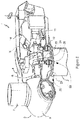
- Figure 1 illustrates a perspective view of one example of a wind turbine 1.
- the wind turbine 1 includes a tower 2 extending from a support surface 3, a nacelle 4 mounted on the tower 2, and a rotor 5 coupled to the nacelle 4.
- the rotor 5 includes a rotatable hub 6 and at least one rotor blade 7 coupled to and extending outwardly from the hub 6.
- the rotor 5 includes three rotor blades 7.
- the rotor 5 may include more or less than three rotor blades 7.
- Each rotor blade 7 may be spaced from the hub 6 to facilitate rotating the rotor 5 to enable kinetic energy to be transferred from the wind into usable mechanical energy, and subsequently, electrical energy.
- the hub 6 may be rotatably coupled to an electric generator 10 ( Figure 2 ) positioned within the nacelle 4 or forming part of the nacelle to permit electrical energy to be produced.
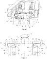
- FIG. 2 illustrates a simplified, internal view of one example of the nacelle 4 of the wind turbine 1 of the Figure 1 .
- the generator 10 may be disposed within the nacelle 4.
- the generator 10 may be coupled to the rotor 5 of the wind turbine 1 for generating electrical power from the rotational energy generated by the rotor 5.
- the rotor 5 may include a main rotor shaft 8 coupled to the hub 5 for rotation therewith.
- the generator 10 may then be coupled to the rotor shaft 8 such that rotation of the rotor shaft 8 drives the generator 10.
- the generator 10 includes a generator shaft 11 rotatably coupled to the rotor shaft 8 through a gearbox 9.
- rotor shaft 8, gearbox 9, and generator 10 may generally be supported within the nacelle 4 by a bedplate or a support frame 12 positioned atop the wind turbine tower 2.
- the nacelle 4 is rotatably coupled to the tower 2 through a yaw system 20.
- the yaw system comprises a yaw bearing (not visible in Figure 2 ) having two bearing components configured to rotate with respect to the other.
- the tower 2 is coupled to one of the bearing components and the bedplate or support frame 12 of the nacelle 4 is coupled to the other bearing component.
- the yaw system 20 comprises an annular gear 21 and a plurality of yaw drives 22 with a motor 23, a gearbox 24 and a pinion 25 for meshing with the annular gear for rotating one of the bearing components with respect to the other.
- Figure 3 illustrates an isometric view of a yaw system according to one example.
- the yaw system 20 comprises a gliding yaw bearing 30 having a first bearing component 31 coupled to the tower 2 and a second bearing component 32 coupled to or forming part of the support frame 12 of the nacelle 4, i.e. comprising a portion of the support frame 12.
- the first bearing component 31 is a gliding plate or gliding track or a gliding disk
- the second bearing component 32 is a bearing guide or a guiding pad assembly.
- the guiding pad assembly or bearing guide may comprise a portion of the support frame 12 and the gliding track or gliding plate may comprise a portion of a tower 2 or may be coupled to the tower.
- the gliding plate may comprise a portion of a tower adapter, the tower adapter extending along a vertical axis and configured to be fixedly coupled to a top portion of a wind turbine tower. Between these two bearing components a gliding assembly (not visible in Figure 3 ) may be arranged to reduce the friction between them.
- the yaw system may comprise an annular gear 21 coupled to the tower 2 and a plurality of yaw drives 22 coupled to the support frame 12.
- the yaw drives 22 comprise a motor and a pinion 25 for meshing with the annular gear 21.
- the rotation of the pinon may rotate the pinion with respect to annular gear 21.
- the annular gear 21 is coupled to the first bearing component 31.
- the first bearing component 31 may therefore rotate with respect to the second bearing component 32.
- the annular gear 21 may comprise a plurality of teeth which engage with the teeth of the pinion 25.
- the yaw drives 22 and the annular gear 21 are placed outside the external diameter of the tower.
- the teeth of the annular gear are outwardly orientated.
- the annular gear 21 may be connected, e.g. welded or fastened, to the bearing or gliding plate.
- the annular gear 21 and the gliding plate may form an integral part.
- the gliding plate may slide with respect to the guiding pad assembly which may partially enclose the gliding plate.
- the guiding pad assembly may comprise a top and a bottom axial gliding surface and a radial gliding surface. Such surfaces may define a C-shape.
- the gliding plate may be arranged between these gliding surfaces. The guiding pad assembly may thus guide the rotation of the gliding plate.
- the guiding pad assembly is placed in a radially inner side and the gliding plate in a radially outer side of the gliding yaw bearing.
- the gliding plate or gliding track may therefore extend radially inwardly towards the rotational axis of the nacelle, whereas the guiding pad assembly may extend radially outwardly from the rotational axis of the nacelle.
- the gliding plate may be placed in a radially inner side and the guiding pad assembly in a radially outer side.
- the yaw system of Figure 3 further comprises a braking disk 40 and one or more braking units 41 configured to exert a braking force on the braking disk 40 for braking or blocking the rotation of the first bearing component 31, e.g. a gliding plate, with respect to the second bearing component 32, e.g. a guiding pad assembly.
- the braking disk 40 may be coupled to the first bearing component 31.
- the braking disk and the guiding plate are connected to the tower, e.g. welded or through fasteners.
- the braking disk and/or the gliding plate may be integrally formed with a tower section or with a tower adapter configured to be connected to the top portion of a wind turbine tower. They may be made in a single piece, e.g. by casting.
- the braking disk may extend 360° around the rotational axis.
- the braking disk may extend less than 360°, e.g. 90° - 270°, around the rotational axis.
- the braking units 41 or brake calipers may be attached to the support frame 12 and may engage with the braking disk 40 to block rotation of the nacelle with respect to the tower.
- the braking units 41 may comprise a pair of braking pads movable relative towards each other for clamping the braking disk. The braking pads may therefore provide the braking force for braking the rotation of the nacelle or for maintaining a yawing orientation.
- Braking units may be passive or active. In some examples, some braking units may be passive and other active.
- Passive braking units may comprise a spring for passively moving the braking pads towards each other.
- the spring may be connected to one of the braking pad which may provide a frictional force against the braking disk.
- Active braking units may comprise a driving system for moving the braking pads towards each other.
- the driving system may control the force exerted by the braking pads on the braking disk.
- the driving system may be a piston attached to one of the braking pads.
- the driving system may include a pair of pistons, each of them attached to one of the braking pads.
- the driving system may hydraulic or electromechanical.
- the activation and deactivation of the active braking units may be controlled by a wind turbine control.
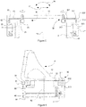
- Figure 4 schematically illustrates a yaw system 20 with external yaw drives 22 with a pinion 25 that engages an annular gear 21 coupled to the tower 2.
- the first bearing component 31 is a guiding plate or guiding track connected to the annular gear 21 and to the tower 2.
- the gliding plate may be integrally formed with at least one of the annular gear 21 or the tower 2 or tower adapter connected to a top portion of a tower.
- the gliding plate or track may thus comprise a portion of the tower or of the tower adapter.
- the gliding plate may be formed by several parts or elements.
- the second bearing component 32 is a bearing guide or guiding caliper or guiding pad assembly connected to the support frame 12 which may rotate with respect to the first bearing component 31 around a rotational axis 19 by the action of the pinion 25 or other driving mechanisms.
- the guiding pad assembly may be formed by an integral piece or may be formed by joining several parts. In some examples, the guiding pad assembly may comprise a portion of the support frame.
- a pair of braking units 41 having movable braking pads 42 may be connected to the second bearing component 32. The braking pads 42 may clamp the braking disk 40 coupled to the tower 2 for blocking yawing movement of the nacelle.
- a gliding assembly 50 may be arranged between the first bearing component 31 and the second bearing component 32.
- the first bearing component 31 may include a top axial gliding surface 311, a bottom axial gliding surface 312 and a radial gliding surface 313.
- the second bearing component 32 may partially enclose the second bearing component.
- the second bearing component 32 may also include a top axial gliding surface 321, a bottom axial gliding surface 322 and a radial gliding surface 323.
- the top axial gliding surface 311 of the first bearing component 31 may face the top axial gliding surface 321 of the second bearing component 32.
- the bottom axial gliding surfaces and the radial gliding surfaces may respectively face to each other.
- the bearing components may have three gliding surfaces. These gliding surfaces may limit undesirable movements of the second bearing components with respect to the first bearing component. Loads may therefore be more efficiently transmitted to the tower.
- Variable loads of the wind acting on wind turbine blades may be transmitted through the support frame 12 to the tower. These loads acting on the blades may produce a tower fore aft movement 18, which tries to modify the tilt of the nacelle. This may create an up and down movement of opposite parts of the nacelle.
- the top 311 and the bottom axial gliding surface 313 of the first bearing component 31 limits such an up and down movement of the nacelle 4 by limiting the movement of the second bearing component 32 with respect to the first bearing component 31.
- Loads on the blades may also produce a thrust force 17 trying to produce a backward and a forward movement of the nacelle.
- the radial gliding surface 312 of the first bearing component 31 may limit the backward and forward movement of the nacelle by blocking the horizontal movement of the second bearing component 32.
- the gliding assembly 50 arranged between the bearing components may comprise a plurality of gliding pads.
- the gliding assembly 50 may comprise one or more top axial gliding pads 51 arranged between the top axial gliding surfaces 311,321 of the first and the second bearing components, one or more bottom axial gliding pads 53 arranged between the bottom axial gliding surfaces 313, 323 of the first and the second bearing components; and one or more radial gliding pads 52 arranged between the radial gliding surfaces 312, 313 of the first and the second bearing components.
- the friction between the gliding surfaces of the bearing components may be controlled.
- the gliding pads may include grease or lubrication in order to reduce the friction coefficient and reduce or control noise. Vibrations of the nacelle may also be absorbed by the gliding pads of the gliding assembly 50.
- one or more of the gliding pads may comprise a pressure system for controlling the pressure provided by the gliding pads to the gliding surfaces. The friction between the adjacent gliding surfaces may thus be controlled.
- the pressure system may comprise a spring or a bolt that adjust the pressure between the two bearing components.
- the pressure system may comprise pneumatic or hydraulic pre-tension elements.
- Figure 5 schematically illustrates an example of a yaw system 20 wherein the yaw drives 22 are arranged in the inner side of the gliding yaw bearing, i.e. inside the diameter defined by the tower.
- the annular gear 21 may be coupled to the tower 2 and the teeth may therefore be inwardly oriented for meshing the pinion 25 of the yaw drives 22.
- the braking module 41 may be coupled to the second bearing component 32 and may engage with braking disk 40 coupled to the tower 2.
- the first bearing component 31, e.g. a gliding plate, is placed in a radially inner side and the second bearing component 32, a guiding pad assembly, in a radially outer side of the gliding yaw bearing.
- the aperture of the guiding pad assembly may face inside the tower.
- the first bearing component 31 and the second bearing component 32 may comprise top axial gliding surface 311 and 321, bottom axial gliding surfaces 313 and 323 and radial axial gliding surfaces 312 and 322. These gliding surfaces may allow minimizing undesired movements or vibrations of the nacelle with respect to the tower, in particular tower fore-aft movements 18 or those produced by the thrust force 17.
- a gliding assembly 20 including a top axial gliding pad 51, a radial gliding pad 52 and a bottom gliding pad 53 may be arranged between the adjacent gliding surfaces.
- the yaw drives 22 may be coupled to the tower (directly or through an intermediate piece) and the annular gear 21 to the frame 12.
- the yaw drives may be arranged inside or outside the tower.
- the first bearing component may be a guiding pad assembly and the second bearing component may be a gliding plate.
- the first bearing component and the second bearing may alternatively be placed in an inner side or in an outer side of the gliding yaw system.
- FIG. 6 schematically illustrates a tower adapter 90 according to one example.
- the tower adapter 90 extends along a vertical axis 92 and is configured to be fixedly coupled to a top portion of wind turbine tower (not illustrated in Figure 6 ) and to be rotatably coupled to a wind turbine nacelle 4.
- the tower adapter 90 comprises a first bearing component 31 that may engage with a second bearing component 32 associated with the nacelle 4 to form a gliding yaw bearing 30.
- the second bearing component 32 may be coupled to the support frame 12.
- the tower adapter may further comprise a braking disk 40 for receiving a braking force from one or more braking units 41 coupled to the support frame 12.
- the braking disk 40 and the braking units 41 may be according to any of the examples herein described.
- the braking disk 40 may extend 360° around the vertical axis.
- the braking disk may extend less than 360° around the vertical axis.
- the braking disk 40 may be arranged apart from the first bearing component 31.
- the braking disk 40 may be arranged on the bottom portion of the tower adapter and the first bearing component 31 on the top portion. Contamination of the braking disk 40 from the oil or grease of the gliding yaw bearing 30 may thus be reduced.
- the tower adapter 90 may comprise a flange 91 for connecting, e.g. bolting, to the top portion of the tower. A fixed connection between the tower adapter 90 and the tower may thus be established.
- the flange 91 may comprise the braking disk 40.
- the first bearing component 31 may comprise a top axial gliding surface 311, a bottom axial gliding surface 313 and a radial gliding surface 312. These gliding surfaces may engage with the corresponding gliding surfaces of a second bearing component 32.
- the first bearing component may be a bearing plate or a gliding plate or a gliding disk. The gliding plate may extend inwardly towards the vertical axis 92, i.e. from the wall of the tower adapter towards the vertical axis 92.
- the second bearing component 32 e.g. the guiding pad assembly
- the second bearing component 32 may be integrally formed with the support frame 12.
- the second bearing component may be formed from several pieces joined, e.g. welded or bolted, to the support frame 12.
- the gliding yaw bearing 30 that may be formed with the first bearing component 31 of the tower adapter 90 and the second bearing component 32 coupled to the nacelle may be according to any of the examples herein described.
- the tower adapter 90 may comprise an annular gear 21 for meshing with the pinions of yaw drives mounted on the nacelle. Meshing the pinion with annular gear makes the nacelle rotate with respect to the tower adapter.
- the tower adapter may comprise one or more yaw drive supports for supporting the yaw drives. The yaw drive may therefore mesh with an annular gear mounted on the nacelle.
- a tower adapter may be used in a method for refurbishing or reconditioning a wind turbine.
- Refurbishing or reconditioning a wind turbine allows using a more efficient technology and components on existing base components, e.g. a foundation and/or a tower.
- existing base components e.g. a foundation and/or a tower.
- a new more technologically advanced machine head and a yaw drive can be provided onto an existing tower or onto a portion of an existing tower. Accordingly, additional life and more efficient power generation can be provided with reduced capital expenses. For this reason, refurbishing a wind turbine may also be called repowering.
- a tower adaptor may be used to connect a machine head, i.e. a rotor and a nacelle including a generator, to a wind turbine tower portion or to an existing wind turbine tower.
- the diameters of a top flange of the existing tower and a new yaw bearing may generally be different.
- a tower adapter may be used to transition from the diameter of the top flange of the tower to the diameter of the yaw bearing.
- the tower adapter may thus allow coupling a new yaw bearing to a top flange of a tower.
- the tower adapter may comprise a flange for connecting, e.g. bolting, to the top flange of the tower.
- a fixed connection between the tower adapter and the tower may thus be established.
- a new machine head may thus be coupled to an existing tower or tower portion.
- One side of the tower adapter may thus have a flange with (inner and outer) diameters corresponding to a top flange of the tower, whereas the upper side of the tower adapter incorporates the first bearing component of suitable diameter to form the yaw mechanism.
- a wind turbine comprises a nacelle, a tower and a yaw system for rotating the nacelle with the respect to the tower around a rotational axis.
- the wind turbine may comprise the yaw system according to any of the examples herein described.
- the wind turbine may comprise a tower adapter connected to the top portion of the wind tower according to any of the examples herein described.
- the vertical axis of the tower adapter may correspond to the rotational axis of the nacelle with respect to the tower.
Landscapes
- Engineering & Computer Science (AREA)
- General Engineering & Computer Science (AREA)
- Mechanical Engineering (AREA)
- Life Sciences & Earth Sciences (AREA)
- Sustainable Development (AREA)
- Sustainable Energy (AREA)
- Chemical & Material Sciences (AREA)
- Combustion & Propulsion (AREA)
- Wind Motors (AREA)
Claims (12)
- Système de lacet (20) destiné à la rotation d'une nacelle (4) par rapport à une tour (2) autour d'un axe de rotation (19) dans une éolienne (1) comprenant :un palier à glissement à lacet (30) comprenant un premier composant palier (31) conçu pour être accouplé à une tour (2), un second composant palier (32) conçu pour être accouplé à une nacelle (4) et un ensemble à glissement (50) disposé entre le premier (31) et le second composant palier (32), dans lequel le premier composant palier (31) est conçu pour tourner par rapport au second composant palier (32) ;un engrenage annulaire (21) et une pluralité d'entraînements de lacet (22) comportant un moteur (23) et un pignon (25) destiné à l'engrenage avec l'engrenage annulaire (21) destiné à la rotation du premier système palier (31) par rapport au second système palier (32) ;un disque de freinage (40) ; etau moins une unité de freinage (41) conçue pour exercer une force de freinage sur le disque de freinage (40) destinée au freinage de la rotation du premier composant palier (31) par rapport au second composant palier (32),ledit système de lacet étant caractérisé en ce que le disque de freinage (40) est séparé des premier (31) et second (32) composants paliers.
- Système de lacet (20) selon la revendication 1, dans lequel les premier (31) et second composants paliers (32) comprennent une surface de glissement axiale (311, 321) supérieure, une surface de glissement axiale (312, 322) inférieure et une surface de glissement radiale (313, 323).
- Système de lacet (20) selon la revendication 2, dans lequel l'ensemble à glissement (50) comprend :au moins un patin de glissement axial (51) supérieur disposé entre les surfaces de glissement axiales (311, 321) supérieures des premier (31) et second composants paliers (32) ;au moins un patin de glissement axial (53) inférieur disposé entre les surfaces de glissement axiales (312, 322) inférieures des premier (31) et second composants paliers (32) ; etau moins un patin de glissement radial (52) disposé entre les surfaces de glissement axiales (313, 323) des premier (31) et second composants paliers (32).
- Système de lacet (20) selon l'une quelconque des revendications 1 à 3, dans lequel l'un des composants paliers (31, 32) est une plaque à glissement et l'autre des composants paliers est un ensemble de patins de guidage enfermant partiellement la plaque à glissement.
- Système de lacet (20) selon la revendication 4, dans lequel l'ensemble de patins de guidage est placé dans un côté radialement intérieur et la plaque à glissement dans un côté radialement extérieur du palier à glissement à lacet (30).
- Système de lacet (20) selon la revendication 5, dans lequel l'ensemble de patins de guidage comprend une partie d'un cadre de support (12) d'une nacelle (4).
- Système de lacet (20) selon l'une quelconque des revendications 5 à 6, dans lequel la plaque à glissement comprend une partie d'un adaptateur de tour (90), l'adaptateur de tour (90) s'étendant le long d'un axe vertical (92) et est conçue pour être accouplée de manière fixe à une partie supérieure d'une tour d'éolienne (2).
- Système de lacet (20) selon la revendication 4, dans lequel la plaque à glissement est placée dans un côté radialement intérieur et l'ensemble de patins de guidage dans un côté radialement extérieur du palier à glissement à lacet (30).
- Système de lacet (20) selon l'une quelconque des revendications 1 à 8, dans lequel le disque de freinage (40) est accouplé au premier composant palier (31).
- Système de lacet (20) selon l'une quelconque des revendications 1 à 9, dans lequel les unités de freinage (41) comprennent une paire de patins de freinage (42) mobiles l'un par rapport à l'autre destinées au serrage du disque de freinage (40).
- Système de lacet (20) selon l'une quelconque des revendications 1 à 10, dans lequel l'au moins une des unités de freinage (41) est passive.
- Éolienne (1) comprenant un système de lacet (20) selon l'une quelconque des revendications 1 à 11.
Priority Applications (4)
| Application Number | Priority Date | Filing Date | Title |
|---|---|---|---|
| ES18382549T ES2899126T3 (es) | 2018-07-20 | 2018-07-20 | Sistema de orientación para una turbina eólica |
| EP18382549.6A EP3597903B1 (fr) | 2018-07-20 | 2018-07-20 | Système de lacet pour éolienne |
| PL18382549T PL3597903T3 (pl) | 2018-07-20 | 2018-07-20 | System odchylania do turbiny wiatrowej |
| US16/517,915 US11092140B2 (en) | 2018-07-20 | 2019-07-22 | Yaw system for a wind turbine |
Applications Claiming Priority (1)
| Application Number | Priority Date | Filing Date | Title |
|---|---|---|---|
| EP18382549.6A EP3597903B1 (fr) | 2018-07-20 | 2018-07-20 | Système de lacet pour éolienne |
Publications (2)
| Publication Number | Publication Date |
|---|---|
| EP3597903A1 EP3597903A1 (fr) | 2020-01-22 |
| EP3597903B1 true EP3597903B1 (fr) | 2021-08-25 |
Family
ID=63103889
Family Applications (1)
| Application Number | Title | Priority Date | Filing Date |
|---|---|---|---|
| EP18382549.6A Active EP3597903B1 (fr) | 2018-07-20 | 2018-07-20 | Système de lacet pour éolienne |
Country Status (4)
| Country | Link |
|---|---|
| US (1) | US11092140B2 (fr) |
| EP (1) | EP3597903B1 (fr) |
| ES (1) | ES2899126T3 (fr) |
| PL (1) | PL3597903T3 (fr) |
Families Citing this family (4)
| Publication number | Priority date | Publication date | Assignee | Title |
|---|---|---|---|---|
| ES2976473T3 (es) * | 2019-12-20 | 2024-08-01 | Vestas Wind Sys As | Un aerogenerador con un sistema de guiñada |
| CN111648918A (zh) * | 2020-05-13 | 2020-09-11 | 包红喜 | 一种使用寿命长的风力发电设备 |
| CN111677628A (zh) * | 2020-06-18 | 2020-09-18 | 盘锦华晨石油装备制造有限公司 | 一种自调节转向的风力发电机 |
| EP4108944B1 (fr) * | 2021-06-24 | 2024-04-17 | Siemens Gamesa Renewable Energy A/S | Assemblage de palier d'orientation |
Family Cites Families (13)
| Publication number | Priority date | Publication date | Assignee | Title |
|---|---|---|---|---|
| EP1571334A1 (fr) * | 2004-03-04 | 2005-09-07 | Gamesa Eolica, S.A. (Sociedad Unipersonal) | Dispositif et procédé de maintien d'une éolienne orientable dans la direction du vent |
| DE102005001344B4 (de) * | 2005-01-11 | 2014-04-10 | Friedrich Klinger | Windenergieanlage |
| DE102008013864B4 (de) * | 2008-03-12 | 2014-12-18 | Nordex Energy Gmbh | Verfahren und Vorrichtung zum Drehen einer Komponente einer Windenergieanlage |
| BRPI0921939A2 (pt) * | 2009-06-16 | 2016-01-05 | Mitsubishi Heavy Ind Ltd | gerador de turbina eólica |
| DE102009049769A1 (de) * | 2009-10-16 | 2011-04-21 | Suzlon Energy Gmbh | Lageranordnung für eine Windturbine |
| CN102216610B (zh) * | 2010-02-10 | 2014-08-20 | 三菱重工业株式会社 | 修理风力涡轮发电机的轴承的方法 |
| JP5495979B2 (ja) * | 2010-06-28 | 2014-05-21 | 三菱重工業株式会社 | 風力発電装置 |
| JP4699571B1 (ja) * | 2010-08-31 | 2011-06-15 | 三菱重工業株式会社 | 風力発電装置の保守方法 |
| DE102011010830A1 (de) * | 2011-02-04 | 2012-08-09 | Tembra Gmbh & Co. Kg | Pneumatische Azimutbremse |
| EP2837818B1 (fr) * | 2013-08-13 | 2018-12-05 | Siemens Aktiengesellschaft | Éolienne avec dispositif de levage de palier de lacet |
| DE102016002006A1 (de) * | 2015-11-20 | 2017-05-24 | Liebherr-Components Biberach Gmbh | Verstelleinheit, Windkraftanlage mit einer solchen Verstelleinheit und Verfahren zum Steuern einer solchen Verstelleinheit |
| KR101768340B1 (ko) * | 2015-12-07 | 2017-08-14 | 두산중공업 주식회사 | 요 브레이크 시스템 |
| US10655600B2 (en) * | 2017-11-08 | 2020-05-19 | General Electric Company | Bi-directional clutch for wind turbine yaw locking system |
-
2018
- 2018-07-20 EP EP18382549.6A patent/EP3597903B1/fr active Active
- 2018-07-20 ES ES18382549T patent/ES2899126T3/es active Active
- 2018-07-20 PL PL18382549T patent/PL3597903T3/pl unknown
-
2019
- 2019-07-22 US US16/517,915 patent/US11092140B2/en active Active
Non-Patent Citations (1)
| Title |
|---|
| None * |
Also Published As
| Publication number | Publication date |
|---|---|
| US11092140B2 (en) | 2021-08-17 |
| PL3597903T3 (pl) | 2021-12-27 |
| EP3597903A1 (fr) | 2020-01-22 |
| US20200025179A1 (en) | 2020-01-23 |
| ES2899126T3 (es) | 2022-03-10 |
Similar Documents
| Publication | Publication Date | Title |
|---|---|---|
| US11092140B2 (en) | Yaw system for a wind turbine | |
| US8021101B2 (en) | Wind turbine and method of assembling the same | |
| WO2014002296A1 (fr) | Procédé d'assemblage d'une ligne d'arbres d'un dispositif générateur de puissance à énergie récupérée, et outil d'assemblage d'une ligne d'arbres | |
| US11280320B2 (en) | Yaw system for a wind turbine | |
| EP3165764B1 (fr) | Frein de lacet pour éolienne | |
| US8469664B2 (en) | Yaw bearing assembly and tower for wind turbine | |
| EP4031763B1 (fr) | Frein d'orientation d'éolienne à douille de freinage en rotation | |
| JP2019526012A (ja) | 風力タービン用のナセル及びロータ並びに方法 | |
| DK201670436A1 (en) | Wind turbine with a yawing system and a method thereof | |
| EP3771842B1 (fr) | Roulements de pale de rotor | |
| US9200619B2 (en) | Wind turbine yaw or pitch bearing utilizing a threaded bearing surface | |
| US20190195197A1 (en) | Rotor arresting device for a wind turbine and method | |
| US11598317B2 (en) | Yaw bearings for a wind turbine | |
| KR20170000672U (ko) | 풍력 발전기의 요 브레이크 장치 | |
| JP5615465B2 (ja) | 再生エネルギー型発電装置の軸系組立て方法及び軸系組立て治具 |
Legal Events
| Date | Code | Title | Description |
|---|---|---|---|
| PUAI | Public reference made under article 153(3) epc to a published international application that has entered the european phase |
Free format text: ORIGINAL CODE: 0009012 |
|
| STAA | Information on the status of an ep patent application or granted ep patent |
Free format text: STATUS: THE APPLICATION HAS BEEN PUBLISHED |
|
| AK | Designated contracting states |
Kind code of ref document: A1 Designated state(s): AL AT BE BG CH CY CZ DE DK EE ES FI FR GB GR HR HU IE IS IT LI LT LU LV MC MK MT NL NO PL PT RO RS SE SI SK SM TR |
|
| AX | Request for extension of the european patent |
Extension state: BA ME |
|
| STAA | Information on the status of an ep patent application or granted ep patent |
Free format text: STATUS: REQUEST FOR EXAMINATION WAS MADE |
|
| 17P | Request for examination filed |
Effective date: 20200722 |
|
| RBV | Designated contracting states (corrected) |
Designated state(s): AL AT BE BG CH CY CZ DE DK EE ES FI FR GB GR HR HU IE IS IT LI LT LU LV MC MK MT NL NO PL PT RO RS SE SI SK SM TR |
|
| GRAP | Despatch of communication of intention to grant a patent |
Free format text: ORIGINAL CODE: EPIDOSNIGR1 |
|
| STAA | Information on the status of an ep patent application or granted ep patent |
Free format text: STATUS: GRANT OF PATENT IS INTENDED |
|
| RIC1 | Information provided on ipc code assigned before grant |
Ipc: F03D 7/02 20060101AFI20200929BHEP |
|
| INTG | Intention to grant announced |
Effective date: 20201028 |
|
| GRAJ | Information related to disapproval of communication of intention to grant by the applicant or resumption of examination proceedings by the epo deleted |
Free format text: ORIGINAL CODE: EPIDOSDIGR1 |
|
| STAA | Information on the status of an ep patent application or granted ep patent |
Free format text: STATUS: REQUEST FOR EXAMINATION WAS MADE |
|
| GRAP | Despatch of communication of intention to grant a patent |
Free format text: ORIGINAL CODE: EPIDOSNIGR1 |
|
| STAA | Information on the status of an ep patent application or granted ep patent |
Free format text: STATUS: GRANT OF PATENT IS INTENDED |
|
| INTC | Intention to grant announced (deleted) | ||
| INTG | Intention to grant announced |
Effective date: 20210224 |
|
| GRAS | Grant fee paid |
Free format text: ORIGINAL CODE: EPIDOSNIGR3 |
|
| GRAA | (expected) grant |
Free format text: ORIGINAL CODE: 0009210 |
|
| STAA | Information on the status of an ep patent application or granted ep patent |
Free format text: STATUS: THE PATENT HAS BEEN GRANTED |
|
| AK | Designated contracting states |
Kind code of ref document: B1 Designated state(s): AL AT BE BG CH CY CZ DE DK EE ES FI FR GB GR HR HU IE IS IT LI LT LU LV MC MK MT NL NO PL PT RO RS SE SI SK SM TR |
|
| REG | Reference to a national code |
Ref country code: CH Ref legal event code: EP |
|
| REG | Reference to a national code |
Ref country code: IE Ref legal event code: FG4D Ref country code: AT Ref legal event code: REF Ref document number: 1424049 Country of ref document: AT Kind code of ref document: T Effective date: 20210915 |
|
| REG | Reference to a national code |
Ref country code: DE Ref legal event code: R096 Ref document number: 602018022339 Country of ref document: DE |
|
| REG | Reference to a national code |
Ref country code: LT Ref legal event code: MG9D |
|
| REG | Reference to a national code |
Ref country code: NL Ref legal event code: FP |
|
| REG | Reference to a national code |
Ref country code: AT Ref legal event code: MK05 Ref document number: 1424049 Country of ref document: AT Kind code of ref document: T Effective date: 20210825 |
|
| PG25 | Lapsed in a contracting state [announced via postgrant information from national office to epo] |
Ref country code: PT Free format text: LAPSE BECAUSE OF FAILURE TO SUBMIT A TRANSLATION OF THE DESCRIPTION OR TO PAY THE FEE WITHIN THE PRESCRIBED TIME-LIMIT Effective date: 20211227 Ref country code: NO Free format text: LAPSE BECAUSE OF FAILURE TO SUBMIT A TRANSLATION OF THE DESCRIPTION OR TO PAY THE FEE WITHIN THE PRESCRIBED TIME-LIMIT Effective date: 20211125 Ref country code: LT Free format text: LAPSE BECAUSE OF FAILURE TO SUBMIT A TRANSLATION OF THE DESCRIPTION OR TO PAY THE FEE WITHIN THE PRESCRIBED TIME-LIMIT Effective date: 20210825 Ref country code: BG Free format text: LAPSE BECAUSE OF FAILURE TO SUBMIT A TRANSLATION OF THE DESCRIPTION OR TO PAY THE FEE WITHIN THE PRESCRIBED TIME-LIMIT Effective date: 20211125 Ref country code: AT Free format text: LAPSE BECAUSE OF FAILURE TO SUBMIT A TRANSLATION OF THE DESCRIPTION OR TO PAY THE FEE WITHIN THE PRESCRIBED TIME-LIMIT Effective date: 20210825 Ref country code: RS Free format text: LAPSE BECAUSE OF FAILURE TO SUBMIT A TRANSLATION OF THE DESCRIPTION OR TO PAY THE FEE WITHIN THE PRESCRIBED TIME-LIMIT Effective date: 20210825 Ref country code: SE Free format text: LAPSE BECAUSE OF FAILURE TO SUBMIT A TRANSLATION OF THE DESCRIPTION OR TO PAY THE FEE WITHIN THE PRESCRIBED TIME-LIMIT Effective date: 20210825 Ref country code: HR Free format text: LAPSE BECAUSE OF FAILURE TO SUBMIT A TRANSLATION OF THE DESCRIPTION OR TO PAY THE FEE WITHIN THE PRESCRIBED TIME-LIMIT Effective date: 20210825 Ref country code: FI Free format text: LAPSE BECAUSE OF FAILURE TO SUBMIT A TRANSLATION OF THE DESCRIPTION OR TO PAY THE FEE WITHIN THE PRESCRIBED TIME-LIMIT Effective date: 20210825 |
|
| PG25 | Lapsed in a contracting state [announced via postgrant information from national office to epo] |
Ref country code: LV Free format text: LAPSE BECAUSE OF FAILURE TO SUBMIT A TRANSLATION OF THE DESCRIPTION OR TO PAY THE FEE WITHIN THE PRESCRIBED TIME-LIMIT Effective date: 20210825 Ref country code: GR Free format text: LAPSE BECAUSE OF FAILURE TO SUBMIT A TRANSLATION OF THE DESCRIPTION OR TO PAY THE FEE WITHIN THE PRESCRIBED TIME-LIMIT Effective date: 20211126 |
|
| REG | Reference to a national code |
Ref country code: ES Ref legal event code: FG2A Ref document number: 2899126 Country of ref document: ES Kind code of ref document: T3 Effective date: 20220310 |
|
| PG25 | Lapsed in a contracting state [announced via postgrant information from national office to epo] |
Ref country code: DK Free format text: LAPSE BECAUSE OF FAILURE TO SUBMIT A TRANSLATION OF THE DESCRIPTION OR TO PAY THE FEE WITHIN THE PRESCRIBED TIME-LIMIT Effective date: 20210825 |
|
| REG | Reference to a national code |
Ref country code: DE Ref legal event code: R097 Ref document number: 602018022339 Country of ref document: DE |
|
| PG25 | Lapsed in a contracting state [announced via postgrant information from national office to epo] |
Ref country code: SM Free format text: LAPSE BECAUSE OF FAILURE TO SUBMIT A TRANSLATION OF THE DESCRIPTION OR TO PAY THE FEE WITHIN THE PRESCRIBED TIME-LIMIT Effective date: 20210825 Ref country code: SK Free format text: LAPSE BECAUSE OF FAILURE TO SUBMIT A TRANSLATION OF THE DESCRIPTION OR TO PAY THE FEE WITHIN THE PRESCRIBED TIME-LIMIT Effective date: 20210825 Ref country code: RO Free format text: LAPSE BECAUSE OF FAILURE TO SUBMIT A TRANSLATION OF THE DESCRIPTION OR TO PAY THE FEE WITHIN THE PRESCRIBED TIME-LIMIT Effective date: 20210825 Ref country code: EE Free format text: LAPSE BECAUSE OF FAILURE TO SUBMIT A TRANSLATION OF THE DESCRIPTION OR TO PAY THE FEE WITHIN THE PRESCRIBED TIME-LIMIT Effective date: 20210825 Ref country code: CZ Free format text: LAPSE BECAUSE OF FAILURE TO SUBMIT A TRANSLATION OF THE DESCRIPTION OR TO PAY THE FEE WITHIN THE PRESCRIBED TIME-LIMIT Effective date: 20210825 Ref country code: AL Free format text: LAPSE BECAUSE OF FAILURE TO SUBMIT A TRANSLATION OF THE DESCRIPTION OR TO PAY THE FEE WITHIN THE PRESCRIBED TIME-LIMIT Effective date: 20210825 |
|
| PLBE | No opposition filed within time limit |
Free format text: ORIGINAL CODE: 0009261 |
|
| STAA | Information on the status of an ep patent application or granted ep patent |
Free format text: STATUS: NO OPPOSITION FILED WITHIN TIME LIMIT |
|
| PG25 | Lapsed in a contracting state [announced via postgrant information from national office to epo] |
Ref country code: IT Free format text: LAPSE BECAUSE OF FAILURE TO SUBMIT A TRANSLATION OF THE DESCRIPTION OR TO PAY THE FEE WITHIN THE PRESCRIBED TIME-LIMIT Effective date: 20210825 |
|
| 26N | No opposition filed |
Effective date: 20220527 |
|
| PG25 | Lapsed in a contracting state [announced via postgrant information from national office to epo] |
Ref country code: SI Free format text: LAPSE BECAUSE OF FAILURE TO SUBMIT A TRANSLATION OF THE DESCRIPTION OR TO PAY THE FEE WITHIN THE PRESCRIBED TIME-LIMIT Effective date: 20210825 |
|
| PG25 | Lapsed in a contracting state [announced via postgrant information from national office to epo] |
Ref country code: MC Free format text: LAPSE BECAUSE OF FAILURE TO SUBMIT A TRANSLATION OF THE DESCRIPTION OR TO PAY THE FEE WITHIN THE PRESCRIBED TIME-LIMIT Effective date: 20210825 |
|
| REG | Reference to a national code |
Ref country code: CH Ref legal event code: PL |
|
| REG | Reference to a national code |
Ref country code: BE Ref legal event code: MM Effective date: 20220731 |
|
| PG25 | Lapsed in a contracting state [announced via postgrant information from national office to epo] |
Ref country code: LU Free format text: LAPSE BECAUSE OF NON-PAYMENT OF DUE FEES Effective date: 20220720 Ref country code: LI Free format text: LAPSE BECAUSE OF NON-PAYMENT OF DUE FEES Effective date: 20220731 Ref country code: CH Free format text: LAPSE BECAUSE OF NON-PAYMENT OF DUE FEES Effective date: 20220731 |
|
| PG25 | Lapsed in a contracting state [announced via postgrant information from national office to epo] |
Ref country code: BE Free format text: LAPSE BECAUSE OF NON-PAYMENT OF DUE FEES Effective date: 20220731 |
|
| P01 | Opt-out of the competence of the unified patent court (upc) registered |
Effective date: 20230529 |
|
| PG25 | Lapsed in a contracting state [announced via postgrant information from national office to epo] |
Ref country code: IE Free format text: LAPSE BECAUSE OF NON-PAYMENT OF DUE FEES Effective date: 20220720 |
|
| PGFP | Annual fee paid to national office [announced via postgrant information from national office to epo] |
Ref country code: ES Payment date: 20230801 Year of fee payment: 6 |
|
| PGFP | Annual fee paid to national office [announced via postgrant information from national office to epo] |
Ref country code: DE Payment date: 20230620 Year of fee payment: 6 |
|
| PG25 | Lapsed in a contracting state [announced via postgrant information from national office to epo] |
Ref country code: HU Free format text: LAPSE BECAUSE OF FAILURE TO SUBMIT A TRANSLATION OF THE DESCRIPTION OR TO PAY THE FEE WITHIN THE PRESCRIBED TIME-LIMIT; INVALID AB INITIO Effective date: 20180720 |
|
| PG25 | Lapsed in a contracting state [announced via postgrant information from national office to epo] |
Ref country code: MK Free format text: LAPSE BECAUSE OF FAILURE TO SUBMIT A TRANSLATION OF THE DESCRIPTION OR TO PAY THE FEE WITHIN THE PRESCRIBED TIME-LIMIT Effective date: 20210825 Ref country code: CY Free format text: LAPSE BECAUSE OF FAILURE TO SUBMIT A TRANSLATION OF THE DESCRIPTION OR TO PAY THE FEE WITHIN THE PRESCRIBED TIME-LIMIT Effective date: 20210825 |
|
| PGFP | Annual fee paid to national office [announced via postgrant information from national office to epo] |
Ref country code: GB Payment date: 20240620 Year of fee payment: 7 |
|
| PGFP | Annual fee paid to national office [announced via postgrant information from national office to epo] |
Ref country code: NL Payment date: 20240619 Year of fee payment: 7 |
|
| PGFP | Annual fee paid to national office [announced via postgrant information from national office to epo] |
Ref country code: FR Payment date: 20240619 Year of fee payment: 7 |
|
| PGFP | Annual fee paid to national office [announced via postgrant information from national office to epo] |
Ref country code: PL Payment date: 20240621 Year of fee payment: 7 |