EP3597589B1 - Fluidbereitstellungsvorrichtung - Google Patents
Fluidbereitstellungsvorrichtung Download PDFInfo
- Publication number
- EP3597589B1 EP3597589B1 EP19183517.2A EP19183517A EP3597589B1 EP 3597589 B1 EP3597589 B1 EP 3597589B1 EP 19183517 A EP19183517 A EP 19183517A EP 3597589 B1 EP3597589 B1 EP 3597589B1
- Authority
- EP
- European Patent Office
- Prior art keywords
- signal line
- side part
- convex portion
- dispenser
- nozzle
- Prior art date
- Legal status (The legal status is an assumption and is not a legal conclusion. Google has not performed a legal analysis and makes no representation as to the accuracy of the status listed.)
- Active
Links
Images


Classifications
-
- F—MECHANICAL ENGINEERING; LIGHTING; HEATING; WEAPONS; BLASTING
- F16—ENGINEERING ELEMENTS AND UNITS; GENERAL MEASURES FOR PRODUCING AND MAINTAINING EFFECTIVE FUNCTIONING OF MACHINES OR INSTALLATIONS; THERMAL INSULATION IN GENERAL
- F16L—PIPES; JOINTS OR FITTINGS FOR PIPES; SUPPORTS FOR PIPES, CABLES OR PROTECTIVE TUBING; MEANS FOR THERMAL INSULATION IN GENERAL
- F16L35/00—Special arrangements used in connection with end fittings of hoses, e.g. safety or protecting devices
- F16L35/005—Nozzles
-
- B—PERFORMING OPERATIONS; TRANSPORTING
- B67—OPENING, CLOSING OR CLEANING BOTTLES, JARS OR SIMILAR CONTAINERS; LIQUID HANDLING
- B67D—DISPENSING, DELIVERING OR TRANSFERRING LIQUIDS, NOT OTHERWISE PROVIDED FOR
- B67D7/00—Apparatus or devices for transferring liquids from bulk storage containers or reservoirs into vehicles or into portable containers, e.g. for retail sale purposes
- B67D7/06—Details or accessories
-
- B—PERFORMING OPERATIONS; TRANSPORTING
- B67—OPENING, CLOSING OR CLEANING BOTTLES, JARS OR SIMILAR CONTAINERS; LIQUID HANDLING
- B67D—DISPENSING, DELIVERING OR TRANSFERRING LIQUIDS, NOT OTHERWISE PROVIDED FOR
- B67D7/00—Apparatus or devices for transferring liquids from bulk storage containers or reservoirs into vehicles or into portable containers, e.g. for retail sale purposes
- B67D7/06—Details or accessories
- B67D7/32—Arrangements of safety or warning devices; Means for preventing unauthorised delivery of liquid
- B67D7/3218—Arrangements of safety or warning devices; Means for preventing unauthorised delivery of liquid relating to emergency shut-off means
-
- F—MECHANICAL ENGINEERING; LIGHTING; HEATING; WEAPONS; BLASTING
- F17—STORING OR DISTRIBUTING GASES OR LIQUIDS
- F17C—VESSELS FOR CONTAINING OR STORING COMPRESSED, LIQUEFIED OR SOLIDIFIED GASES; FIXED-CAPACITY GAS-HOLDERS; FILLING VESSELS WITH, OR DISCHARGING FROM VESSELS, COMPRESSED, LIQUEFIED, OR SOLIDIFIED GASES
- F17C5/00—Methods or apparatus for filling containers with liquefied, solidified, or compressed gases under pressures
- F17C5/06—Methods or apparatus for filling containers with liquefied, solidified, or compressed gases under pressures for filling with compressed gases
-
- B—PERFORMING OPERATIONS; TRANSPORTING
- B60—VEHICLES IN GENERAL
- B60S—SERVICING, CLEANING, REPAIRING, SUPPORTING, LIFTING, OR MANOEUVRING OF VEHICLES, NOT OTHERWISE PROVIDED FOR
- B60S5/00—Servicing, maintaining, repairing, or refitting of vehicles
- B60S5/02—Supplying fuel to vehicles; General disposition of plant in filling stations
-
- B—PERFORMING OPERATIONS; TRANSPORTING
- B67—OPENING, CLOSING OR CLEANING BOTTLES, JARS OR SIMILAR CONTAINERS; LIQUID HANDLING
- B67D—DISPENSING, DELIVERING OR TRANSFERRING LIQUIDS, NOT OTHERWISE PROVIDED FOR
- B67D7/00—Apparatus or devices for transferring liquids from bulk storage containers or reservoirs into vehicles or into portable containers, e.g. for retail sale purposes
- B67D7/04—Apparatus or devices for transferring liquids from bulk storage containers or reservoirs into vehicles or into portable containers, e.g. for retail sale purposes for transferring fuels, lubricants or mixed fuels and lubricants
-
- B—PERFORMING OPERATIONS; TRANSPORTING
- B67—OPENING, CLOSING OR CLEANING BOTTLES, JARS OR SIMILAR CONTAINERS; LIQUID HANDLING
- B67D—DISPENSING, DELIVERING OR TRANSFERRING LIQUIDS, NOT OTHERWISE PROVIDED FOR
- B67D7/00—Apparatus or devices for transferring liquids from bulk storage containers or reservoirs into vehicles or into portable containers, e.g. for retail sale purposes
- B67D7/06—Details or accessories
- B67D7/08—Arrangements of devices for controlling, indicating, metering or registering quantity or price of liquid transferred
-
- B—PERFORMING OPERATIONS; TRANSPORTING
- B67—OPENING, CLOSING OR CLEANING BOTTLES, JARS OR SIMILAR CONTAINERS; LIQUID HANDLING
- B67D—DISPENSING, DELIVERING OR TRANSFERRING LIQUIDS, NOT OTHERWISE PROVIDED FOR
- B67D7/00—Apparatus or devices for transferring liquids from bulk storage containers or reservoirs into vehicles or into portable containers, e.g. for retail sale purposes
- B67D7/06—Details or accessories
- B67D7/08—Arrangements of devices for controlling, indicating, metering or registering quantity or price of liquid transferred
- B67D7/22—Arrangements of indicators or registers
-
- B—PERFORMING OPERATIONS; TRANSPORTING
- B67—OPENING, CLOSING OR CLEANING BOTTLES, JARS OR SIMILAR CONTAINERS; LIQUID HANDLING
- B67D—DISPENSING, DELIVERING OR TRANSFERRING LIQUIDS, NOT OTHERWISE PROVIDED FOR
- B67D7/00—Apparatus or devices for transferring liquids from bulk storage containers or reservoirs into vehicles or into portable containers, e.g. for retail sale purposes
- B67D7/06—Details or accessories
- B67D7/32—Arrangements of safety or warning devices; Means for preventing unauthorised delivery of liquid
-
- B—PERFORMING OPERATIONS; TRANSPORTING
- B67—OPENING, CLOSING OR CLEANING BOTTLES, JARS OR SIMILAR CONTAINERS; LIQUID HANDLING
- B67D—DISPENSING, DELIVERING OR TRANSFERRING LIQUIDS, NOT OTHERWISE PROVIDED FOR
- B67D7/00—Apparatus or devices for transferring liquids from bulk storage containers or reservoirs into vehicles or into portable containers, e.g. for retail sale purposes
- B67D7/06—Details or accessories
- B67D7/32—Arrangements of safety or warning devices; Means for preventing unauthorised delivery of liquid
- B67D7/3281—Details
-
- B—PERFORMING OPERATIONS; TRANSPORTING
- B67—OPENING, CLOSING OR CLEANING BOTTLES, JARS OR SIMILAR CONTAINERS; LIQUID HANDLING
- B67D—DISPENSING, DELIVERING OR TRANSFERRING LIQUIDS, NOT OTHERWISE PROVIDED FOR
- B67D7/00—Apparatus or devices for transferring liquids from bulk storage containers or reservoirs into vehicles or into portable containers, e.g. for retail sale purposes
- B67D7/06—Details or accessories
- B67D7/32—Arrangements of safety or warning devices; Means for preventing unauthorised delivery of liquid
- B67D7/34—Means for preventing unauthorised delivery of liquid
-
- B—PERFORMING OPERATIONS; TRANSPORTING
- B67—OPENING, CLOSING OR CLEANING BOTTLES, JARS OR SIMILAR CONTAINERS; LIQUID HANDLING
- B67D—DISPENSING, DELIVERING OR TRANSFERRING LIQUIDS, NOT OTHERWISE PROVIDED FOR
- B67D7/00—Apparatus or devices for transferring liquids from bulk storage containers or reservoirs into vehicles or into portable containers, e.g. for retail sale purposes
- B67D7/06—Details or accessories
- B67D7/42—Filling nozzles
- B67D7/425—Filling nozzles including components powered by electricity or light
-
- F—MECHANICAL ENGINEERING; LIGHTING; HEATING; WEAPONS; BLASTING
- F16—ENGINEERING ELEMENTS AND UNITS; GENERAL MEASURES FOR PRODUCING AND MAINTAINING EFFECTIVE FUNCTIONING OF MACHINES OR INSTALLATIONS; THERMAL INSULATION IN GENERAL
- F16L—PIPES; JOINTS OR FITTINGS FOR PIPES; SUPPORTS FOR PIPES, CABLES OR PROTECTIVE TUBING; MEANS FOR THERMAL INSULATION IN GENERAL
- F16L37/00—Couplings of the quick-acting type
- F16L37/08—Couplings of the quick-acting type in which the connection between abutting or axially overlapping ends is maintained by locking members
- F16L37/084—Couplings of the quick-acting type in which the connection between abutting or axially overlapping ends is maintained by locking members combined with automatic locking
-
- F—MECHANICAL ENGINEERING; LIGHTING; HEATING; WEAPONS; BLASTING
- F17—STORING OR DISTRIBUTING GASES OR LIQUIDS
- F17C—VESSELS FOR CONTAINING OR STORING COMPRESSED, LIQUEFIED OR SOLIDIFIED GASES; FIXED-CAPACITY GAS-HOLDERS; FILLING VESSELS WITH, OR DISCHARGING FROM VESSELS, COMPRESSED, LIQUEFIED, OR SOLIDIFIED GASES
- F17C13/00—Details of vessels or of the filling or discharging of vessels
-
- F—MECHANICAL ENGINEERING; LIGHTING; HEATING; WEAPONS; BLASTING
- F17—STORING OR DISTRIBUTING GASES OR LIQUIDS
- F17C—VESSELS FOR CONTAINING OR STORING COMPRESSED, LIQUEFIED OR SOLIDIFIED GASES; FIXED-CAPACITY GAS-HOLDERS; FILLING VESSELS WITH, OR DISCHARGING FROM VESSELS, COMPRESSED, LIQUEFIED, OR SOLIDIFIED GASES
- F17C13/00—Details of vessels or of the filling or discharging of vessels
- F17C13/12—Arrangements or mounting of devices for preventing or minimising the effect of explosion ; Other safety measures
-
- F—MECHANICAL ENGINEERING; LIGHTING; HEATING; WEAPONS; BLASTING
- F17—STORING OR DISTRIBUTING GASES OR LIQUIDS
- F17C—VESSELS FOR CONTAINING OR STORING COMPRESSED, LIQUEFIED OR SOLIDIFIED GASES; FIXED-CAPACITY GAS-HOLDERS; FILLING VESSELS WITH, OR DISCHARGING FROM VESSELS, COMPRESSED, LIQUEFIED, OR SOLIDIFIED GASES
- F17C5/00—Methods or apparatus for filling containers with liquefied, solidified, or compressed gases under pressures
- F17C5/002—Automated filling apparatus
- F17C5/007—Automated filling apparatus for individual gas tanks or containers, e.g. in vehicles
-
- F—MECHANICAL ENGINEERING; LIGHTING; HEATING; WEAPONS; BLASTING
- F17—STORING OR DISTRIBUTING GASES OR LIQUIDS
- F17C—VESSELS FOR CONTAINING OR STORING COMPRESSED, LIQUEFIED OR SOLIDIFIED GASES; FIXED-CAPACITY GAS-HOLDERS; FILLING VESSELS WITH, OR DISCHARGING FROM VESSELS, COMPRESSED, LIQUEFIED, OR SOLIDIFIED GASES
- F17C5/00—Methods or apparatus for filling containers with liquefied, solidified, or compressed gases under pressures
- F17C5/02—Methods or apparatus for filling containers with liquefied, solidified, or compressed gases under pressures for filling with liquefied gases
-
- H—ELECTRICITY
- H01—ELECTRIC ELEMENTS
- H01R—ELECTRICALLY-CONDUCTIVE CONNECTIONS; STRUCTURAL ASSOCIATIONS OF A PLURALITY OF MUTUALLY-INSULATED ELECTRICAL CONNECTING ELEMENTS; COUPLING DEVICES; CURRENT COLLECTORS
- H01R13/00—Details of coupling devices of the kinds covered by groups H01R12/70 or H01R24/00 - H01R33/00
- H01R13/62—Means for facilitating engagement or disengagement of coupling parts or for holding them in engagement
- H01R13/629—Additional means for facilitating engagement or disengagement of coupling parts, e.g. aligning or guiding means, levers, gas pressure electrical locking indicators, manufacturing tolerances
- H01R13/633—Additional means for facilitating engagement or disengagement of coupling parts, e.g. aligning or guiding means, levers, gas pressure electrical locking indicators, manufacturing tolerances for disengagement only
- H01R13/635—Additional means for facilitating engagement or disengagement of coupling parts, e.g. aligning or guiding means, levers, gas pressure electrical locking indicators, manufacturing tolerances for disengagement only by mechanical pressure, e.g. spring force
-
- F—MECHANICAL ENGINEERING; LIGHTING; HEATING; WEAPONS; BLASTING
- F02—COMBUSTION ENGINES; HOT-GAS OR COMBUSTION-PRODUCT ENGINE PLANTS
- F02D—CONTROLLING COMBUSTION ENGINES
- F02D19/00—Controlling engines characterised by their use of non-liquid fuels, pluralities of fuels, or non-fuel substances added to the combustible mixtures
- F02D19/02—Controlling engines characterised by their use of non-liquid fuels, pluralities of fuels, or non-fuel substances added to the combustible mixtures peculiar to engines working with gaseous fuels
- F02D19/026—Measuring or estimating parameters related to the fuel supply system
- F02D19/027—Determining the fuel pressure, temperature or volume flow, the fuel tank fill level or a valve position
-
- F—MECHANICAL ENGINEERING; LIGHTING; HEATING; WEAPONS; BLASTING
- F16—ENGINEERING ELEMENTS AND UNITS; GENERAL MEASURES FOR PRODUCING AND MAINTAINING EFFECTIVE FUNCTIONING OF MACHINES OR INSTALLATIONS; THERMAL INSULATION IN GENERAL
- F16L—PIPES; JOINTS OR FITTINGS FOR PIPES; SUPPORTS FOR PIPES, CABLES OR PROTECTIVE TUBING; MEANS FOR THERMAL INSULATION IN GENERAL
- F16L2201/00—Special arrangements for pipe couplings
- F16L2201/20—Safety or protective couplings
-
- F—MECHANICAL ENGINEERING; LIGHTING; HEATING; WEAPONS; BLASTING
- F16—ENGINEERING ELEMENTS AND UNITS; GENERAL MEASURES FOR PRODUCING AND MAINTAINING EFFECTIVE FUNCTIONING OF MACHINES OR INSTALLATIONS; THERMAL INSULATION IN GENERAL
- F16L—PIPES; JOINTS OR FITTINGS FOR PIPES; SUPPORTS FOR PIPES, CABLES OR PROTECTIVE TUBING; MEANS FOR THERMAL INSULATION IN GENERAL
- F16L55/00—Devices or appurtenances for use in, or in connection with, pipes or pipe systems
- F16L55/10—Means for stopping flow in pipes or hoses
- F16L55/1007—Couplings closed automatically when broken
-
- F—MECHANICAL ENGINEERING; LIGHTING; HEATING; WEAPONS; BLASTING
- F17—STORING OR DISTRIBUTING GASES OR LIQUIDS
- F17C—VESSELS FOR CONTAINING OR STORING COMPRESSED, LIQUEFIED OR SOLIDIFIED GASES; FIXED-CAPACITY GAS-HOLDERS; FILLING VESSELS WITH, OR DISCHARGING FROM VESSELS, COMPRESSED, LIQUEFIED, OR SOLIDIFIED GASES
- F17C2205/00—Vessel construction, in particular mounting arrangements, attachments or identifications means
- F17C2205/03—Fluid connections, filters, valves, closure means or other attachments
- F17C2205/0302—Fittings, valves, filters, or components in connection with the gas storage device
- F17C2205/0352—Pipes
- F17C2205/0364—Pipes flexible or articulated, e.g. a hose
-
- F—MECHANICAL ENGINEERING; LIGHTING; HEATING; WEAPONS; BLASTING
- F17—STORING OR DISTRIBUTING GASES OR LIQUIDS
- F17C—VESSELS FOR CONTAINING OR STORING COMPRESSED, LIQUEFIED OR SOLIDIFIED GASES; FIXED-CAPACITY GAS-HOLDERS; FILLING VESSELS WITH, OR DISCHARGING FROM VESSELS, COMPRESSED, LIQUEFIED, OR SOLIDIFIED GASES
- F17C2205/00—Vessel construction, in particular mounting arrangements, attachments or identifications means
- F17C2205/03—Fluid connections, filters, valves, closure means or other attachments
- F17C2205/0302—Fittings, valves, filters, or components in connection with the gas storage device
- F17C2205/0376—Dispensing pistols
-
- F—MECHANICAL ENGINEERING; LIGHTING; HEATING; WEAPONS; BLASTING
- F17—STORING OR DISTRIBUTING GASES OR LIQUIDS
- F17C—VESSELS FOR CONTAINING OR STORING COMPRESSED, LIQUEFIED OR SOLIDIFIED GASES; FIXED-CAPACITY GAS-HOLDERS; FILLING VESSELS WITH, OR DISCHARGING FROM VESSELS, COMPRESSED, LIQUEFIED, OR SOLIDIFIED GASES
- F17C2221/00—Handled fluid, in particular type of fluid
- F17C2221/01—Pure fluids
- F17C2221/012—Hydrogen
-
- F—MECHANICAL ENGINEERING; LIGHTING; HEATING; WEAPONS; BLASTING
- F17—STORING OR DISTRIBUTING GASES OR LIQUIDS
- F17C—VESSELS FOR CONTAINING OR STORING COMPRESSED, LIQUEFIED OR SOLIDIFIED GASES; FIXED-CAPACITY GAS-HOLDERS; FILLING VESSELS WITH, OR DISCHARGING FROM VESSELS, COMPRESSED, LIQUEFIED, OR SOLIDIFIED GASES
- F17C2223/00—Handled fluid before transfer, i.e. state of fluid when stored in the vessel or before transfer from the vessel
- F17C2223/01—Handled fluid before transfer, i.e. state of fluid when stored in the vessel or before transfer from the vessel characterised by the phase
- F17C2223/0107—Single phase
- F17C2223/0123—Single phase gaseous, e.g. CNG, GNC
-
- F—MECHANICAL ENGINEERING; LIGHTING; HEATING; WEAPONS; BLASTING
- F17—STORING OR DISTRIBUTING GASES OR LIQUIDS
- F17C—VESSELS FOR CONTAINING OR STORING COMPRESSED, LIQUEFIED OR SOLIDIFIED GASES; FIXED-CAPACITY GAS-HOLDERS; FILLING VESSELS WITH, OR DISCHARGING FROM VESSELS, COMPRESSED, LIQUEFIED, OR SOLIDIFIED GASES
- F17C2223/00—Handled fluid before transfer, i.e. state of fluid when stored in the vessel or before transfer from the vessel
- F17C2223/03—Handled fluid before transfer, i.e. state of fluid when stored in the vessel or before transfer from the vessel characterised by the pressure level
- F17C2223/036—Very high pressure (>80 bar)
-
- F—MECHANICAL ENGINEERING; LIGHTING; HEATING; WEAPONS; BLASTING
- F17—STORING OR DISTRIBUTING GASES OR LIQUIDS
- F17C—VESSELS FOR CONTAINING OR STORING COMPRESSED, LIQUEFIED OR SOLIDIFIED GASES; FIXED-CAPACITY GAS-HOLDERS; FILLING VESSELS WITH, OR DISCHARGING FROM VESSELS, COMPRESSED, LIQUEFIED, OR SOLIDIFIED GASES
- F17C2225/00—Handled fluid after transfer, i.e. state of fluid after transfer from the vessel
- F17C2225/01—Handled fluid after transfer, i.e. state of fluid after transfer from the vessel characterised by the phase
- F17C2225/0107—Single phase
- F17C2225/0123—Single phase gaseous, e.g. CNG, GNC
-
- F—MECHANICAL ENGINEERING; LIGHTING; HEATING; WEAPONS; BLASTING
- F17—STORING OR DISTRIBUTING GASES OR LIQUIDS
- F17C—VESSELS FOR CONTAINING OR STORING COMPRESSED, LIQUEFIED OR SOLIDIFIED GASES; FIXED-CAPACITY GAS-HOLDERS; FILLING VESSELS WITH, OR DISCHARGING FROM VESSELS, COMPRESSED, LIQUEFIED, OR SOLIDIFIED GASES
- F17C2225/00—Handled fluid after transfer, i.e. state of fluid after transfer from the vessel
- F17C2225/03—Handled fluid after transfer, i.e. state of fluid after transfer from the vessel characterised by the pressure level
- F17C2225/036—Very high pressure, i.e. above 80 bars
-
- F—MECHANICAL ENGINEERING; LIGHTING; HEATING; WEAPONS; BLASTING
- F17—STORING OR DISTRIBUTING GASES OR LIQUIDS
- F17C—VESSELS FOR CONTAINING OR STORING COMPRESSED, LIQUEFIED OR SOLIDIFIED GASES; FIXED-CAPACITY GAS-HOLDERS; FILLING VESSELS WITH, OR DISCHARGING FROM VESSELS, COMPRESSED, LIQUEFIED, OR SOLIDIFIED GASES
- F17C2250/00—Accessories; Control means; Indicating, measuring or monitoring of parameters
- F17C2250/03—Control means
-
- F—MECHANICAL ENGINEERING; LIGHTING; HEATING; WEAPONS; BLASTING
- F17—STORING OR DISTRIBUTING GASES OR LIQUIDS
- F17C—VESSELS FOR CONTAINING OR STORING COMPRESSED, LIQUEFIED OR SOLIDIFIED GASES; FIXED-CAPACITY GAS-HOLDERS; FILLING VESSELS WITH, OR DISCHARGING FROM VESSELS, COMPRESSED, LIQUEFIED, OR SOLIDIFIED GASES
- F17C2250/00—Accessories; Control means; Indicating, measuring or monitoring of parameters
- F17C2250/03—Control means
- F17C2250/036—Control means using alarms
-
- F—MECHANICAL ENGINEERING; LIGHTING; HEATING; WEAPONS; BLASTING
- F17—STORING OR DISTRIBUTING GASES OR LIQUIDS
- F17C—VESSELS FOR CONTAINING OR STORING COMPRESSED, LIQUEFIED OR SOLIDIFIED GASES; FIXED-CAPACITY GAS-HOLDERS; FILLING VESSELS WITH, OR DISCHARGING FROM VESSELS, COMPRESSED, LIQUEFIED, OR SOLIDIFIED GASES
- F17C2250/00—Accessories; Control means; Indicating, measuring or monitoring of parameters
- F17C2250/04—Indicating or measuring of parameters as input values
- F17C2250/0404—Parameters indicated or measured
- F17C2250/0478—Position or presence
-
- F—MECHANICAL ENGINEERING; LIGHTING; HEATING; WEAPONS; BLASTING
- F17—STORING OR DISTRIBUTING GASES OR LIQUIDS
- F17C—VESSELS FOR CONTAINING OR STORING COMPRESSED, LIQUEFIED OR SOLIDIFIED GASES; FIXED-CAPACITY GAS-HOLDERS; FILLING VESSELS WITH, OR DISCHARGING FROM VESSELS, COMPRESSED, LIQUEFIED, OR SOLIDIFIED GASES
- F17C2250/00—Accessories; Control means; Indicating, measuring or monitoring of parameters
- F17C2250/06—Controlling or regulating of parameters as output values
- F17C2250/0605—Parameters
- F17C2250/0636—Flow or movement of content
-
- F—MECHANICAL ENGINEERING; LIGHTING; HEATING; WEAPONS; BLASTING
- F17—STORING OR DISTRIBUTING GASES OR LIQUIDS
- F17C—VESSELS FOR CONTAINING OR STORING COMPRESSED, LIQUEFIED OR SOLIDIFIED GASES; FIXED-CAPACITY GAS-HOLDERS; FILLING VESSELS WITH, OR DISCHARGING FROM VESSELS, COMPRESSED, LIQUEFIED, OR SOLIDIFIED GASES
- F17C2260/00—Purposes of gas storage and gas handling
- F17C2260/04—Reducing risks and environmental impact
-
- F—MECHANICAL ENGINEERING; LIGHTING; HEATING; WEAPONS; BLASTING
- F17—STORING OR DISTRIBUTING GASES OR LIQUIDS
- F17C—VESSELS FOR CONTAINING OR STORING COMPRESSED, LIQUEFIED OR SOLIDIFIED GASES; FIXED-CAPACITY GAS-HOLDERS; FILLING VESSELS WITH, OR DISCHARGING FROM VESSELS, COMPRESSED, LIQUEFIED, OR SOLIDIFIED GASES
- F17C2260/00—Purposes of gas storage and gas handling
- F17C2260/04—Reducing risks and environmental impact
- F17C2260/042—Reducing risk of explosion
-
- F—MECHANICAL ENGINEERING; LIGHTING; HEATING; WEAPONS; BLASTING
- F17—STORING OR DISTRIBUTING GASES OR LIQUIDS
- F17C—VESSELS FOR CONTAINING OR STORING COMPRESSED, LIQUEFIED OR SOLIDIFIED GASES; FIXED-CAPACITY GAS-HOLDERS; FILLING VESSELS WITH, OR DISCHARGING FROM VESSELS, COMPRESSED, LIQUEFIED, OR SOLIDIFIED GASES
- F17C2265/00—Effects achieved by gas storage or gas handling
- F17C2265/06—Fluid distribution
- F17C2265/065—Fluid distribution for refuelling vehicle fuel tanks
-
- F—MECHANICAL ENGINEERING; LIGHTING; HEATING; WEAPONS; BLASTING
- F17—STORING OR DISTRIBUTING GASES OR LIQUIDS
- F17C—VESSELS FOR CONTAINING OR STORING COMPRESSED, LIQUEFIED OR SOLIDIFIED GASES; FIXED-CAPACITY GAS-HOLDERS; FILLING VESSELS WITH, OR DISCHARGING FROM VESSELS, COMPRESSED, LIQUEFIED, OR SOLIDIFIED GASES
- F17C2270/00—Applications
- F17C2270/01—Applications for fluid transport or storage
- F17C2270/0134—Applications for fluid transport or storage placed above the ground
- F17C2270/0139—Fuel stations
-
- H—ELECTRICITY
- H01—ELECTRIC ELEMENTS
- H01R—ELECTRICALLY-CONDUCTIVE CONNECTIONS; STRUCTURAL ASSOCIATIONS OF A PLURALITY OF MUTUALLY-INSULATED ELECTRICAL CONNECTING ELEMENTS; COUPLING DEVICES; CURRENT COLLECTORS
- H01R2201/00—Connectors or connections adapted for particular applications
- H01R2201/26—Connectors or connections adapted for particular applications for vehicles
-
- Y—GENERAL TAGGING OF NEW TECHNOLOGICAL DEVELOPMENTS; GENERAL TAGGING OF CROSS-SECTIONAL TECHNOLOGIES SPANNING OVER SEVERAL SECTIONS OF THE IPC; TECHNICAL SUBJECTS COVERED BY FORMER USPC CROSS-REFERENCE ART COLLECTIONS [XRACs] AND DIGESTS
- Y02—TECHNOLOGIES OR APPLICATIONS FOR MITIGATION OR ADAPTATION AGAINST CLIMATE CHANGE
- Y02E—REDUCTION OF GREENHOUSE GAS [GHG] EMISSIONS, RELATED TO ENERGY GENERATION, TRANSMISSION OR DISTRIBUTION
- Y02E60/00—Enabling technologies; Technologies with a potential or indirect contribution to GHG emissions mitigation
- Y02E60/30—Hydrogen technology
- Y02E60/32—Hydrogen storage
-
- Y—GENERAL TAGGING OF NEW TECHNOLOGICAL DEVELOPMENTS; GENERAL TAGGING OF CROSS-SECTIONAL TECHNOLOGIES SPANNING OVER SEVERAL SECTIONS OF THE IPC; TECHNICAL SUBJECTS COVERED BY FORMER USPC CROSS-REFERENCE ART COLLECTIONS [XRACs] AND DIGESTS
- Y02—TECHNOLOGIES OR APPLICATIONS FOR MITIGATION OR ADAPTATION AGAINST CLIMATE CHANGE
- Y02P—CLIMATE CHANGE MITIGATION TECHNOLOGIES IN THE PRODUCTION OR PROCESSING OF GOODS
- Y02P90/00—Enabling technologies with a potential contribution to greenhouse gas [GHG] emissions mitigation
- Y02P90/45—Hydrogen technologies in production processes
Definitions
- the present invention relates to a fluid supply apparatus for supplying fluid (gas or liquid) including fuel such as hydrogen gas (H 2 ) and gasoline to vehicles and others.
- fluid gas or liquid
- fuel such as hydrogen gas (H 2 ) and gasoline
- a vehicle using hydrogen as fuel in a hydrogen filling station, fills hydrogen gas as a fuel fluid after a filling nozzle mounted on an end of a filling hose and a vehicle side filling port are connected with each other.
- a photodetector mounted on the filling nozzle receives data such as pressure and temperature in a tank sent from the vehicle and sends them to a controller in a housing (hydrogen filling apparatus) through a signal line to properly perform the filling control.
- the filling hose when the filling hose is pulled due to a cause such as movement of a vehicle during filling operation, devices such as the filling nozzle and the filling hose may be broken, and hydrogen gas may jet, which may cause dangerous situations.
- the present applicant proposed an emergency separation pipe joint that separates when more or equal to a predetermined tensile load is added thereto before.
- the above emergency separation pipe joint is effective.
- one signal line is used to connect the photodetector mounted on an end of the filling nozzle and the controller in a housing main body, when more or equal to a predetermined tensile load is added to the emergency separation pipe joint, and the joint is separated, the signal line is cut under the condition that conducting portions thereof are exposed, which may cause a serious accident due to short circuit, which is generated when the conducting portion contacts other metal portion, or contacts between sparks generated by the short circuit and hydrogen gas.
- hydrogen gas is large in buoyant force and high in diffusion velocity, the possibility that the hydrogen gas contacts sparks generated by the short circuit is not low.
- another emergency separation pipe joint is, for example, described in Japanese Patent Publication No. 2007-120717 .
- solution of the above problem on the cut of the signal line is not disclosed.
- an emergency separation coupling 11 and a filling apparatus 1 are connected with each other through a hose 4A and both ends of the hose 4A are connecting portions, there is a problem that leakage risk becomes high due to increased number of connection portions.
- a moving pin 35 in a fitting member 29 on outflow side moves in relation to a seal ring 30B, so that the seal ring 30B is damaged or stuck, which leads to a disadvantage that leakage risk of hydrogen gas from the seal ring 30B becomes high.
- FR 3 009 295 A1 and US 2010/0089486 A1 each describe systems for supplying liquid fuel to a tank, wherein a signal line extends separate of a filling hose through which the fuel is conducted.
- the signal line is described to be detachable from the tank to be filled.
- GB 2485832 A describes fluid supply system comprising a hose for conducting fluid, a signal line integrated into the interior of the hose and a coupling device for combined mechanical and electrical connection of the hose and the signal line.
- a locking mechanism is provided in order to lock the coupler.
- JP 2004 29377 A describes an emergency detachable coupler for a hose conducting high pressure fluid.
- the present invention has been proposed in consideration of the above problems in the prior art, and the object thereof is to provide a fluid supply apparatus capable of preventing inconveniences caused by cut of the signal line when the filling hose is separated through the emergency separation pipe joint.
- a fluid supply apparatus (100: fluid supply apparatus for supplying fluid such as hydrogen gas and gasoline) includes a supply system for transporting fluid such as hydrogen gas and gasoline in a housing main body while measuring flow rate of the fluid; a control mechanism for controlling the supply system; a hose (2) introduced from the supply system and having a nozzle (1) at an end thereof; and a signal line (3) along the hose (2), wherein the signal line (3) is detachable.
- the signal line (3) includes a detachable portion (10, 20: signal line separation mechanism) as a separable portion, and the detachable portion (10, 20) is provided with a locking mechanism (11, 21). Further, to the locking mechanism (11, 21) is mounted an emergency separation mechanism (12, 22) for releasing the locking mechanism (11, 21).
- the locking mechanism (11, 21) includes a signal line holding member (13, 23), to the signal line holding member (13, 23) is mounted a first convex portion (13A, 23A) for releasing engagement of the locking mechanism (11, 21), and emergency separation mechanism (12, 22) includes a lock releasing member (14, 24), and to the lock releasing member (14, 24) is mounted a second convex portion (14A, 24A) for releasing engagement of the locking mechanism(11, 21) by contacting the first convex portion (13A, 23A).
- the first convex portion (13A) of the signal line holding member (13) in a circumferential direction are formed detent projections (13B), and dimension of the second convex portion (14A) of the lock releasing member (14) in the circumferential direction is smaller than a gap between the detent projections (13B).
- the second convex portion (24A) of the lock releasing member (24) is formed on a whole area of the lock releasing member (24) in a circumferential direction.
- the signal line (3) is mounted in loose state, and the signal line (3) is separated at the detachable portion (10, 20) after the hose (2) is separated.
- the signal line (3) is detachably mounted, and includes the detachable portion (10, 20) as a separable portion in the middle of the signal line (3), so that the signal line (3) separates at the same portion (the detachable portion (10, 20)).
- the signal line (3) is detachably mounted, and includes the detachable portion (10, 20) as a separable portion in the middle of the signal line (3), so that the signal line (3) separates at the same portion (the detachable portion (10, 20)).
- connecting the separated signal lines (3) at the detachable portion (10, 20) again certainly enables reuse of the signal line (3) with ease. Then, even when the signal line (3) separates, it can be easily restored to its original state before the separation.
- the signal line 3 separates at the detachable portion (10, 20), that is, the signal line 3 does not separate at an unspecified portion.
- the separated signal line 3 is maintained in a condition that conductor portions thereof are not considerably exposed, which can prevent generation of spark due to exposure of the conductor portion of the separated signal line and a fear of contact with hydrogen gas with large buoyancy and high diffusion velocity. Further, since the signal line 3 separates at the detachable portion (10, 20) when more or equal to a predetermined tensile load is added, it can be prevented that the filling apparatus 40 is pulled and fallen down to be damaged.
- the signal line 3 is provided with the detachable portion (10, 20) and the detachable portion (10, 20) has the locking mechanism (11, 21), with the locking mechanism (11, 21), the separable signal lines are maintained in a condition that are connected at the detachable portion (10, 20).
- signals showing data such as pressure and temperature in a tank that are transmitted from the vehicle (50) are sent to the controller in the housing main body through the signal line 3, which performs proper filling operation.
- separation of the signal line 3 can prevent cutting of the signal line 3 and inconvenience due to the cutting such as generation of sparks and contact between hydrogen gas and the sparks. Further, separation of the signal line 3 prevents that the filling apparatus 40 is pulled and fallen down to be damaged by a tensile force applied to the signal line 3.
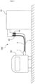
- a hydrogen dispenser for filling hydrogen gas to a vehicle is exemplified.
- a fluid supply apparatus 100 is provided with a supply system not shown for transporting hydrogen gas in a housing main body of a hydrogen dispenser 40 while measuring flow rate of the hydrogen gas; a control mechanism not shown for controlling the supply system.
- a filling hose 2 with a filling nozzle 1 at an end thereof.
- the filling nozzle 1 at an end of the filling hose 2 and a filling spout not shown on the side of the vehicle 50 are connected with each other to fill hydrogen gas.
- an emergency separation pipe joint 30 To the filling hose 2 is mounted an emergency separation pipe joint 30, and when more or equal to a predetermined tensile load is added to the emergency separation pipe joint 30, the pipe joint 30 is separated.
- the emergency separation pipe joint 30 separates to separate the filling hose 2 into one on the hydrogen dispenser 40 side and another on the filling nozzle 1 (vehicle 50) side. With this, it is prevented that the hydrogen dispenser 40 falls down and is damaged to eject hydrogen gas, which is a dangerous situation.
- the signal line 3 On the filling nozzle 1 is mounted a photodetector not shown.
- the photodetector receives signals showing data such as pressure and temperature in a tank sent from a vehicle and sends them to a controller in a main body on the hydrogen dispenser 40 side through the signal line 3 to properly perform the hydrogen filling control.
- the signal line 3 has a detachable portion 10 (signal line separation mechanism) adjacent to the hydrogen dispenser 40. And, the signal line 3 is detachable at the detachable portion 10.
- the detachable portion 10 is provided with a locking mechanism 11 (shown in Fig. 2 ) described below, and to the locking mechanism 11 is mounted the emergency separation mechanism 12, which releases the locking mechanism 11 when more or equal to a predetermined tensile force is added.
- the emergency separation mechanism 12 works to release the locking mechanism 11, and the detachable portion 10 is separated, which causes the signal line 3 to be separated into the hydrogen dispenser 40 side and the filling nozzle 1 side (the vehicle 50 side).
- the signal line 3 is not cut at an unspecified portion other than the detachable portion 10, inconveniences caused by the cut at an unspecified portion such as generation of sparks, contact between hydrogen gas and sparks and repair works for the signal line 3 are prevented.
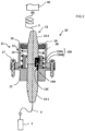
- Fig. 2 whole of the detachable portion (signal line separation mechanism) is indicated by the numeral 10, and the detachable portion 10 is provided with a base member 15, a casing 16 and mounting bolts 17 for fixing the casing 16 to the base member 15.
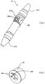
- the base member 15 and the casing 16 have opening portions at central portions in radial directions (left and right directions), through the opening portions passes the signal line holding member 13 (refer to Fig. 3 ) in the shape of long and narrow rotating body.
- the signal line holding member 13 is, as shown in Fig. 6 , separable into a nozzle side part 13-1 (the lower part in Fig. 6 ) and a dispenser side part 13-2 (the upper part in Fig. 6 )
- Fig. 2 To the signal line holding member 13 is connected the signal line 3, and the signal line 3 is connected to the filling nozzle 1 and the hydrogen dispenser 40. Illustration of the signal line 3 is omitted in Figs. 5 and 6 .
- a portion of the signal line 3 connected on the hydrogen dispenser 40 side (a portion connected to the dispenser side part 13-2 side) is loosened.
- a tensile force (less than predetermined value) is added to the signal line holding member 13 through the signal line 3 connected to the filling nozzle 1, even though the signal line holding member 13 is pulled on the filling nozzle 1 side (even though it becomes the condition shown in Fig.
- the first convex portion 13A adjacent to a boundary with the nozzle side part 13-1 in an axial direction (up-and-down direction in Fig. 2 ), and to the first convex portion 13A is mounted a pressing portion 13AA and a locking portion 13AB.
- the pressing portion 13AA and the locking portion 13AB are clearly illustrated in Figs. 5 and 6 also.
- the first convex portion 13A usually projects from outside of the dispenser side part 13-2 in a circumferential direction, and pressing the pressing portion 13AA inwardly in a radial direction allows the first convex portion 13A to be embedded inwardly in a radial direction.
- the detent projections 13B are formed on both sides of the first convex portion 13A in a circumferential direction.
- a locked portion 13C adjacent to the boundary with the dispenser side part 13-2.
- the locked portion 13C is illustrated in Figs. 5 and 6 also.
- a channel for embedment into which the locking portion 13AB of the first convex portion 13A of the dispenser side part 13-2 is embedded, and when the first convex portion 13A projects outwardly in a radial direction of the dispenser side part 13-2 during a normal period, the channel for embedment and the locking portion 13AB engage with each other as shown in Fig. 2 , and the nozzle side part 13-1 and the dispenser side part 13-2 are connected with each other.
- the signal line holding member 13 can be used well-known products for example goods on the market.
- the locking mechanism 11 of the detachable portion 10 includes the nozzle side part 13-1 to which the locked portion 13C is mounted, the dispenser side part 13-2 to which the first convex portion 13A is mounted, an emergency separation mechanism 12 described below for releasing engagement of the locking mechanism 11, the base member 15, the casing 16 and others.
- a spring (coil spring) 18 and a spring press plate 19 in the casing 16 is accommodated the lock releasing member 14, a spring (coil spring) 18 and a spring press plate 19.
- the lock releasing member 14 is mounted inside the spring 18 in a radial direction, and is formed in a hollow shape with an opening at a central portion in a radial direction. Through the opening portion of the lock releasing member 14 passes the dispenser side part 13-2, and in the hollow portion of the lock releasing member 14 is disposed the signal line holding member 13.
- the lock releasing member 14 is formed in a shape of a hollow body, and on the lock releasing member 14 are formed a second convex portion 14A projecting inward in a radial direction and a concave portion 14b described below.
- the second convex portion 14A is formed at a position corresponding to the first convex portion 13A of the dispenser side part 13-2 in a circumferential direction.
- an area where the second convex portion 14A is formed and an area where the second convex portion 14A is not formed are connected with each other through a smoothly inclined portion (tapered portion) as shown in Fig. 2 .
- a projecting amount that projects inward in a radial direction is set as much as necessary and sufficiently, when by the second convex portion 14A is pressed the first convex portion 13A of the dispenser side part 13-2 inwardly in a radial direction, to release engagement between the first convex portion 13A and the locked portion 13C of the nozzle side part 13-1 and separate into the nozzle side part 13-1 and the dispenser side part 13-2.
- the emergency separation mechanism 12 includes the lock releasing member 14 to which the second convex portion 14A is formed, the spring 18, the spring press plate 19 and others.
- the spring press plate 19 is fixed to the dispenser side part 13-2, and when the dispenser side part 13-2 moves in a longitudinal direction (axial direction, up-and-down direction in Fig. 2 ), the spring press plate 19 also moves in the longitudinal direction together with the dispenser side part 13-2.
- Fig.2 shows a condition that no tensile force is applied to the signal line 3 connected to the filling nozzle 1, so that the first convex portion 13A of the dispenser side part 13-2 positions opposite to the area where the second convex portion 14A of the lock releasing member 14 is not formed in a longitudinal direction (up-and-down direction in Fig. 2 ).
- the first convex portion 13A is not pressed inward in a radial direction, and the first convex portion 13A does not separate into the nozzle side part 13-1 and the dispenser side part 13-2, and they are integrally connected with each other to maintain a condition that the signal line 3 extends from the filling nozzle 1 to the hydrogen dispenser 40.
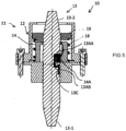
- the spring press plate 19 reaches to an upper face portion of the lock releasing member 14 to depress the dispenser side part 13-2, so that the first convex portion 13A moves downward (goes down in Figs. 2 , 5 and 6 ) to an area where the second convex portion 14A is formed through a tapered portion of the lock releasing member 14.
- the first convex portion 13A is pressed inward in a radial direction by the second convex portion 14A of the lock releasing member 14.
- the condition that the first convex portion 13A is pressed inward in a radial direction by the second convex portion 14A is shown in Figs. 5 and 6 .
- the nozzle side part 13-1 and the dispenser side part 13-2 are separated from each other. That is, action of the emergency separation mechanism 12 allows the locking mechanism 11 of the signal line holding member 13 to be released, which causes the nozzle side part 13-1 and the dispenser side part 13-2 to be separated from each other. Due to the separation of the nozzle side part 13-1 and the dispenser side part 13-2, the tensile force acting on the signal line 3 on the nozzle side is not transmitted to the signal line 3 on the dispenser 40 side, so that there is no fear that the tensile force causes the hydrogen dispenser 40 to fall down and to be damaged.
- the spring press plate 19 contacts an upper face portion of the lock releasing member 14, so that the dispenser side part 13-2 integrally connected to the spring press plate 19 does not move on the filling nozzle 1 side (downward in Figs. 5 and 6 ) from the positions shown in Figs. 5 and 6 .
- elastic repulsive force of the spring 18 in the casing 16 is set in such a manner that amount of deformation of the spring 18 when a tensile force more or equal to a predetermined value acts on the signal line 3 is less or equal to a loosened amount of the signal line 3 on the hydrogen dispenser 40 side. Then, the amount of deformation of the spring 18 when a tensile force more or equal to a predetermined value acts is set to become an amount of movement (amount of fall in Figs. 2 and 5 ) of the first convex portion 13A of the dispenser side part 13-2 toward an area where the second convex portion 14A of the lock releasing member 14 is formed.
- the first convex portion 13A of the dispenser side part 13-2 moves (falls in Figs. 2 , 5 and 6 ) to the area where the second convex portion 14A of the lock releasing member 14 is formed to release the locking mechanism 11 of the signal line holding member 13, which causes the nozzle side part 13-1 and the dispenser side part 13-2 to separate from each other.
- the first convex portion 13A of the dispenser side part 13-2 does not move to the area where the second convex portion 14A of the lock releasing member 14 is formed, so that the locking mechanism 11 of the signal line holding member 13 is not released, which causes the nozzle side part 13-1 and the dispenser side part 13-2 not to be separated from each other.
- the nozzle side part 13-1 and the dispenser side part 13-2 are connected with each other again, and it returns to the condition that the filling nozzle 1 is electrically connected to the hydrogen dispenser 40 through the signal line 3 (the state shown in Fig. 2 ).
- a pair of detent projections 13B At both sides of the first convex portion 13A of the dispenser side part 13-2 of the signal line holding member 13 in a circumferential direction are formed a pair of detent projections 13B.
- the distance between the detent projections 13B (circumferential distance) is set slightly larger than the width, in a circumferential direction, of the second convex portion 14A of the lock releasing member 14.
- the detent projections 13B of the dispenser side part 13-2 move on the filling nozzle 1 side (downward in Fig. 2 ) while putting the second convex portion 14A of the lock releasing member 14 between them.
- the signal line 3 when more or equal to a predetermined value of tensile force is added to the signal line 3, the signal line 3 has the detachable portion 10 (signal line separation mechanism) in midway and is detachably mounted, so that the signal line 3 always separates at the detachable portion 10 and is not cut at an unspecified portion. Then, connecting the separated signal lines 3 at the detachable portion 10 again allows the condition before separation to easily and certainly be restored, and the separated signal lines 3 to be reused.
- the detachable portion 10 signal line separation mechanism
- the signal line 3 separates at the detachable portion 10, which prevents exposure of a conducting portion of the signal line 3, so that generation of sparks and contact between hydrogen gas and sparks due to the exposure of the conducting portion of the signal line 3 can be prevented.
- the signal line 3 separates at the detachable portion 10 when more or equal to a predetermined value of tensile force is added, it is prevented that the hydrogen dispenser 40 is pulled and fallen down to be damaged.
- the locking mechanism 11 of the detachable portion 10 separable signal lines are held at the detachable portion 10 under a condition that they are connected. Therefore, signals showing data transmitted from the vehicle 50 such as pressure and temperature in a tank are sent to a controlling device in the housing main body of the hydrogen dispenser 40 through the signal line 3 to perform proper filling control. Then, the locking mechanism 11 mechanically acts, resulting in secure and safe operation.
- the dispenser side part 13-2 are formed a pair of detent projections 13B on both sides of the first convex portion 13A in a circumferential direction, and in the lock releasing member 14 in an area where the second convex portion 14A is not formed, the detent projections 13B and the concave portion 14b abut with each other to form a detent for preventing relative movement between the lock releasing member 14 and the dispenser side part 13-2 in a circumferential direction.
- the second convex portion 14A of the lock releasing member 14 certainly presses the first convex portion 13A of the dispenser side part 13-2 inwardly in a radial direction.
- a detent is formed in such a manner that the lock releasing member 14 and the signal line holding member 13 do not relatively move in a circumferential direction.
- the second convex portion 24A certainly presses the first convex portion 23A inward in a radial direction to separate the signal line holding member 23 into the nozzle side part 23-1 and the dispenser side part 23-2.
- the signal line holding member 23 is separable into the nozzle side part 23-1 and the dispenser side part 23-2.
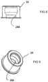
- the signal line holding member 23 in the emergency separation mechanism 22 of the second embodiment, in the signal line holding member 23 (dispenser side part 23-2), no detent projection is formed on both sides of the first convex part 23A in a circumferential direction. Comparing the signal line holding member 23, the nozzle side part 23-1 and the dispenser side part 23-2 with the signal line holding member 13, the nozzle side part 13-1 and the dispenser side part 13-2 of the first embodiment, only that no detent projection is formed on both sides of the first convex part 23A is different.
- the second convex portion 24A is formed so as to inwardly project in a radial direction.
- a condition that the signal line 3 is connected and fixed by the locking mechanism 21 is illustrated in Fig. 10 .
- Fig. 10 a condition that the signal line 3 is connected and fixed by the locking mechanism 21 (corresponding to the condition shown in Fig. 2 in the first embodiment) is illustrated in Fig. 10 .
- the second convex portion 24A of the lock releasing member 24 since the second convex portion 24A is formed over the entire periphery on the inner side of the lock releasing member 24, when more or equal to a predetermined value of tensile force is added to the signal line 3, regardless of relative positions of the lock releasing member 24 and the signal line holding member 23 in a circumferential direction, the second convex portion 24A of the lock releasing member 24 certainly presses the first convex part 23A of the dispenser side part 23-2 inward in a radial direction. As a result, the signal line holding member 23 separates into the nozzle side part 23-1 and the dispenser side part 23-2. Constructions and action effects of the second embodiment shown in Figs. 7 to 10 other than the above are the same as those of the first embodiment shown in Figs. 1 to 6 .
Landscapes
- Engineering & Computer Science (AREA)
- Mechanical Engineering (AREA)
- General Engineering & Computer Science (AREA)
- Physics & Mathematics (AREA)
- Theoretical Computer Science (AREA)
- Mathematical Physics (AREA)
- Chemical & Material Sciences (AREA)
- Oil, Petroleum & Natural Gas (AREA)
- General Chemical & Material Sciences (AREA)
- Chemical Kinetics & Catalysis (AREA)
- Filling Or Discharging Of Gas Storage Vessels (AREA)
- Loading And Unloading Of Fuel Tanks Or Ships (AREA)
- Details Of Connecting Devices For Male And Female Coupling (AREA)
Claims (8)
- Fluidzufuhrvorrichtung (100), umfassend:ein Zufuhrsystem zum Transportieren von Fluid in einem Gehäusehauptkörper, während die Strömungsrate des Fluids gemessen wird;einen Steuermechanismus zum Steuern des Zufuhrsystems;einen Schlauch (2), der von dem Zufuhrsystem eingeführt ist und an einem Ende davon einen Stutzen (1) aufweist;eine Signalleitung (3), die sich entlang einer Außenseite des Schlauchs (2) erstreckt, wobei die Signalleitung (3) lösbar ist und einen lösbaren Abschnitt (10; 20) als einen trennbaren Abschnitt aufweist, wobei der lösbare Abschnitt mit einem Verriegelungsmechanismus (11; 21) versehen ist, der ein Signalleitungshalteelement (13; 23) aufweist, wobei ein erster konvexer Abschnitt (13A; 23A) zum Freigeben des Eingriffs des Verriegelungsmechanismus (11; 21) an dem Signalleitungshalteelement (13; 23) montiert ist; undeinen Nottrennmechanismus (12; 22), der montiert ist, um den Verriegelungsmechanismus (11; 21) freizugeben, wobei der Nottrennmechanismus (12; 22) ein Verriegelungsfreigabeelement (14; 24) aufweist;wobei ein zweiter konvexer Abschnitt (14A; 24A) zum Freigeben des Eingriffs des Verriegelungsmechanismus (11; 21) durch Berühren des ersten konvexen Abschnitts (13A; 23A) an dem Verriegelungsfreigabeelement (14; 24) montiert ist.
- Fluidzufuhrvorrichtung (100) nach Anspruch 1, wobei auf beiden Seiten des ersten konvexen Abschnitts (13A) in einer Umfangsrichtung Arretierungsvorsprünge (13B) gebildet sind und eine Abmessung des zweiten konvexen Abschnitts (14A) in der Umfangsrichtung kleiner ist als ein Spalt zwischen den Arretierungsvorsprüngen (13B).
- Fluidzufuhrvorrichtung (100) nach Anspruch 1, wobei auf beiden Seiten des ersten konvexen Abschnitts (23A) in einer Umfangsrichtung keine Arretierungsvorsprünge gebildet sind und der zweite konvexe Abschnitt (23A) auf einem gesamten Bereich des Verriegelungsfreigabeelements (24) in einer Umfangsrichtung gebildet ist.
- Fluidzufuhrvorrichtung (100) nach einem der vorhergehenden Ansprüche, wobei das Zufuhrsystem zum Transportieren von Wasserstoffgas in einem Gehäusehauptkörper einer Wasserstoffabgabeeinrichtung (40) eingerichtet ist, wobei die Signalleitung (3) auf einer Seite der Wasserstoffabgabeeinrichtung des Stutzens (1) montiert ist, wobei der lösbare Abschnitt (10; 20) der Signalleitung (3) benachbart zu der Wasserstoffabgabeeinrichtung (40) ist, und wobei ein Photodetektor an den Füllstutzen (1) montiert ist, wobei der Photodetektor eingerichtet ist, um Signale zu empfangen, die Druck- und Temperaturdaten in einem Tank eines Fahrzeugs (50) zeigen, und um diese an den Steuermechanismus, der in dem Hauptkörper auf der Seite der Wasserstoffabgabeeinrichtung (40) vorgesehen ist, durch die Signalleitung (3) zu senden, um eine Wasserstofffüllsteuerung durchzuführen.
- Fluidzufuhrvorrichtung (100) nach einem der vorhergehenden Ansprüche, wobei das Signalleitungshalteelement (13; 23) einen stutzenseitigen Teil (13-1; 23-1) und einen abgabeeinrichtungsseitigen Teil (13-2; 23-2) umfasst, wobei ein Abschnitt der Signalleitung (3) mit dem Stutzen (1) und dem stutzenseitigen Teil (13-1; 23-1) verbunden ist und ein anderer Abschnitt der Signalleitung (3) mit dem abgabeeinrichtungsseitigen Teil (13-2; 23-2) verbunden ist, und wobei der stutzenseitige Teil (13-1; 23-1) und der abgabeeinrichtungsseitige Teil (13-2; 23-2) trennbar sind.
- Fluidzufuhrvorrichtung (100) nach Anspruch 5, wobei der erste konvexe Abschnitt (13A; 23A) an dem abgabeeinrichtungsseitigen Teil (13-2) des Signalleitungshalteelements (13) benachbart zu einer Grenze mit dem stutzenseitigen Teil (13-1) in einer axialen Richtung montiert ist, wobei ein Druckabschnitt (13AA; 23AA) und ein Verriegelungsabschnitt (13AB; 23AB) an dem ersten konvexen Abschnitt (13A; 23A) montiert sind, und wobei ein verriegelter Abschnitt (13C; 23C) an dem stutzenseitigen Teil (13-1; 23-1) des Signalleitungshalteelements (13; 23) benachbart zu der Grenze mit dem abgabeeinrichtungsseitigen Teil (13-2; 23-2) montiert ist.
- Fluidzufuhrvorrichtung (100) nach Anspruch 6, wobei der erste konvexe Abschnitt (13A; 23A) von der Außenseite des abgabeeinrichtungsseitigen Teils (13-2; 23-2) in einer Umfangsrichtung vorsteht, wobei ein Drücken des Druckabschnitts (13AA; 23AA) nach innen in einer radialen Richtung ermöglicht, dass der erste konvexe Abschnitt (13A; 23A) nach innen in der radialen Richtung eingebettet wird, und wobei der verriegelte Abschnitt (13C; 23C) als ein Kanal gebildet ist, in den der Verriegelungsabschnitt (13AB; 23AB) des ersten konvexen Abschnitts (13A; 23A) des abgabeeinrichtungsseitigen Teils (13-2; 23-2) eingebettet ist, so dass der Kanal und der Verriegelungsabschnitt 13AB ineinander eingreifen, wenn der erste konvexe Abschnitt (13A; 23A) während einer normalen Periode in der radialen Richtung des abgabeeinrichtungsseitigen Teils (13-2; 23-2) nach außen vorsteht.
- Fluidzufuhrvorrichtung (100) nach Anspruch 7, wobei das Verriegelungsfreigabeelement (14; 24) in Form eines Hohlkörpers gebildet ist, wobei der zweite konvexe Abschnitt (14A) auf dem Verriegelungsfreigabeelement (14; 24) gebildet ist, um in der radialen Richtung nach innen vorzustehen, wobei der zweite konvexe Abschnitt (14A; 24A) an einer Position gebildet ist, die dem ersten konvexen Abschnitt (13A; 23A) des abgabeeinrichtungsseitigen Teils (13-2; 23-2) in der Umfangsrichtung entspricht, wobei ein Bereich, in dem der zweite konvexe Abschnitt (14A; 24A) gebildet ist, und ein Bereich, in dem der zweite konvexe Abschnitt (14A; 24A) nicht gebildet ist, durch einen geneigten Abschnitt miteinander verbunden sind, wobei in dem zweiten konvexen Abschnitt (14A; 24A) ein vorstehender Betrag, der in der radialen Richtung nach innen vorsteht, so viel wie notwendig und ausreichend festgelegt ist, um den Eingriff zwischen dem ersten konvexen Abschnitt (13A; 23A) und dem verriegelten Abschnitt (13C; 23C) des stutzenseitigen Teils (13-1; 23-1) freizugeben und in den stutzenseitigen Teil (13-1; 23-1) und den abgabeeinrichtungsseitigen Teil (13-2; 23-2) zu trennen, wenn der erste konvexe Abschnitt (13A; 23A) des abgabeeinrichtungsseitigen Teils (13-2; 23-2) in der radialen Richtung durch den zweiten konvexen Abschnitt (14A; 24A) nach innen gedrückt wird.
Applications Claiming Priority (1)
| Application Number | Priority Date | Filing Date | Title |
|---|---|---|---|
| JP2018125965A JP6736031B2 (ja) | 2018-07-02 | 2018-07-02 | 供給装置 |
Publications (2)
| Publication Number | Publication Date |
|---|---|
| EP3597589A1 EP3597589A1 (de) | 2020-01-22 |
| EP3597589B1 true EP3597589B1 (de) | 2023-06-21 |
Family
ID=67137780
Family Applications (1)
| Application Number | Title | Priority Date | Filing Date |
|---|---|---|---|
| EP19183517.2A Active EP3597589B1 (de) | 2018-07-02 | 2019-07-01 | Fluidbereitstellungsvorrichtung |
Country Status (5)
| Country | Link |
|---|---|
| US (1) | US10794520B2 (de) |
| EP (1) | EP3597589B1 (de) |
| JP (1) | JP6736031B2 (de) |
| KR (1) | KR102207394B1 (de) |
| CN (1) | CN110671601B (de) |
Cited By (1)
| Publication number | Priority date | Publication date | Assignee | Title |
|---|---|---|---|---|
| WO2025122473A1 (en) * | 2023-12-04 | 2025-06-12 | Contitech Usa, Inc. | Fitting for connecting a hose |
Families Citing this family (4)
| Publication number | Priority date | Publication date | Assignee | Title |
|---|---|---|---|---|
| CN112707363A (zh) * | 2020-12-23 | 2021-04-27 | 天津大沽化工股份有限公司 | 一种苯乙烯液下定量装车方法 |
| US11970931B2 (en) | 2021-06-01 | 2024-04-30 | Halliburton Energy Services, Inc. | Through tubing cement evaluation using borehole resonance mode |
| CN114413172B (zh) * | 2022-03-07 | 2024-11-01 | 成都捷氢新能源科技有限公司 | 一种电子拉断阀、加注站控制系统及其控制方法 |
| JP7614567B2 (ja) | 2023-03-31 | 2025-01-16 | 株式会社タツノ | 充填用ノズルの支持構造 |
Family Cites Families (17)
| Publication number | Priority date | Publication date | Assignee | Title |
|---|---|---|---|---|
| US4269226A (en) * | 1979-12-17 | 1981-05-26 | Aeroquip Corporation | Universal breakaway coupling |
| US4863397A (en) * | 1988-04-22 | 1989-09-05 | Hatch Jr William K | Expendable frangible electrical connector |
| US6334474B1 (en) * | 2001-04-26 | 2002-01-01 | Brent D. Rababy | Breakaway separation detection and alert system |
| JP2004293777A (ja) | 2003-03-11 | 2004-10-21 | Tokico Ltd | 緊急離脱カプラ |
| JP2004353821A (ja) * | 2003-05-30 | 2004-12-16 | Tokico Ltd | ガス充填装置及び離脱カプラ |
| US7070417B2 (en) * | 2004-09-28 | 2006-07-04 | Phillips & Temro Industries Inc. | Breakable connector for connecting a vehicle to a power source |
| JP4366600B2 (ja) * | 2005-01-07 | 2009-11-18 | 株式会社タツノ・メカトロニクス | 緊急離脱管継手 |
| JP2007120717A (ja) | 2005-10-31 | 2007-05-17 | Hitachi Ltd | 緊急離脱カップリング |
| US8051882B2 (en) | 2008-10-15 | 2011-11-08 | Dixon Valve And Coupling Company | Tanker truck monitoring system |
| JP5261408B2 (ja) | 2010-01-25 | 2013-08-14 | トヨタ自動車株式会社 | 燃料ガスステーション、燃料ガス充填システム、燃料ガス供給方法 |
| JP5195863B2 (ja) * | 2010-10-12 | 2013-05-15 | 第一精工株式会社 | 電気コネクタ |
| GB2485832A (en) | 2010-11-26 | 2012-05-30 | Joseph Anthony Griffiths | A combined fluid coupling and data communication connection |
| US20130025698A1 (en) * | 2011-07-28 | 2013-01-31 | Behrouz Safi-Samghabadi | Fuel-pump drive off alert system |
| CA2762697C (en) * | 2011-12-22 | 2021-04-27 | Westport Power Inc. | Method and apparatus for supplying a gaseous fuel to an internal combustion engine |
| KR101919159B1 (ko) * | 2012-11-08 | 2018-11-15 | 엘에스이브이코리아 주식회사 | 커넥터 및 이를 구비하는 고전압 전력용 접속장치 |
| FR3009295B1 (fr) | 2013-07-31 | 2015-08-21 | Qowisio | Systeme de controle de remplissage d'un contenant a partir d'un vehicule se deplacant en differents endroits et procede de mise en oeuvre |
| CA2831762C (en) * | 2013-10-31 | 2015-01-20 | Westport Power Inc. | System and method for delivering a fluid stored in liquefied form to an end user in gaseous form |
-
2018
- 2018-07-02 JP JP2018125965A patent/JP6736031B2/ja active Active
-
2019
- 2019-05-10 KR KR1020190054814A patent/KR102207394B1/ko active Active
- 2019-06-24 US US16/450,429 patent/US10794520B2/en active Active
- 2019-07-01 CN CN201910587099.2A patent/CN110671601B/zh not_active Expired - Fee Related
- 2019-07-01 EP EP19183517.2A patent/EP3597589B1/de active Active
Cited By (1)
| Publication number | Priority date | Publication date | Assignee | Title |
|---|---|---|---|---|
| WO2025122473A1 (en) * | 2023-12-04 | 2025-06-12 | Contitech Usa, Inc. | Fitting for connecting a hose |
Also Published As
| Publication number | Publication date |
|---|---|
| US20200003349A1 (en) | 2020-01-02 |
| KR102207394B1 (ko) | 2021-01-26 |
| KR20200003712A (ko) | 2020-01-10 |
| US10794520B2 (en) | 2020-10-06 |
| CN110671601A (zh) | 2020-01-10 |
| CN110671601B (zh) | 2022-11-08 |
| JP2020001818A (ja) | 2020-01-09 |
| EP3597589A1 (de) | 2020-01-22 |
| JP6736031B2 (ja) | 2020-08-05 |
Similar Documents
| Publication | Publication Date | Title |
|---|---|---|
| EP3597589B1 (de) | Fluidbereitstellungsvorrichtung | |
| CA1079768A (en) | Air bag device for cars | |
| EP2436965B1 (de) | Rohrverbindung | |
| CN109237180B (zh) | 安全接头 | |
| US8066298B2 (en) | Coupling system for connecting supply lines | |
| EP2368305A1 (de) | Ladevorrichtung für elektrisch betreibbares fahrzeug | |
| US4131142A (en) | Safety valve for fuel dispensers including vapor recovery systems | |
| JP6540967B2 (ja) | 管継手 | |
| KR20220024933A (ko) | 수소 저장 시스템 | |
| EP4023929A1 (de) | Füllvorrichtung | |
| US4863397A (en) | Expendable frangible electrical connector | |
| EP3129694B1 (de) | Bidirektionale schlauchabreissanordnung | |
| EP0928693B1 (de) | Verbindung für Auswechselflüssigkeitsbehälter in Tintenstrahldruckern | |
| EP3719381A1 (de) | Füllvorrichtung | |
| JP7205780B2 (ja) | 安全継手 | |
| EP0505767A2 (de) | Vorrichtung zum Blockieren eines Hydraulik- oder Druckluftkreises eines Fahrzeuges, insbesondere Bremskreises oder dergleichen | |
| US7367635B2 (en) | Rail vehicle having an electrical signal line loop | |
| JP2014167875A (ja) | コネクタ装置 | |
| KR20180071547A (ko) | 수소공급밸브와 수소차단밸브 사이의 파단부를 포함하는 연료전지 시스템 | |
| US20030049960A1 (en) | Electric connector | |
| EP3869629B1 (de) | Steckverbinder zur stromversorgung | |
| JP2010086856A (ja) | コネクタ接続構造 | |
| RU2773582C2 (ru) | Предохранительный разъединитель | |
| US1074849A (en) | Automatic train-pipe connector. | |
| KR100435957B1 (ko) | 연료탱크의 체크밸브구조 |
Legal Events
| Date | Code | Title | Description |
|---|---|---|---|
| PUAI | Public reference made under article 153(3) epc to a published international application that has entered the european phase |
Free format text: ORIGINAL CODE: 0009012 |
|
| STAA | Information on the status of an ep patent application or granted ep patent |
Free format text: STATUS: THE APPLICATION HAS BEEN PUBLISHED |
|
| AK | Designated contracting states |
Kind code of ref document: A1 Designated state(s): AL AT BE BG CH CY CZ DE DK EE ES FI FR GB GR HR HU IE IS IT LI LT LU LV MC MK MT NL NO PL PT RO RS SE SI SK SM TR |
|
| AX | Request for extension of the european patent |
Extension state: BA ME |
|
| STAA | Information on the status of an ep patent application or granted ep patent |
Free format text: STATUS: REQUEST FOR EXAMINATION WAS MADE |
|
| 17P | Request for examination filed |
Effective date: 20200306 |
|
| RBV | Designated contracting states (corrected) |
Designated state(s): AL AT BE BG CH CY CZ DE DK EE ES FI FR GB GR HR HU IE IS IT LI LT LU LV MC MK MT NL NO PL PT RO RS SE SI SK SM TR |
|
| GRAP | Despatch of communication of intention to grant a patent |
Free format text: ORIGINAL CODE: EPIDOSNIGR1 |
|
| STAA | Information on the status of an ep patent application or granted ep patent |
Free format text: STATUS: GRANT OF PATENT IS INTENDED |
|
| INTG | Intention to grant announced |
Effective date: 20230411 |
|
| GRAS | Grant fee paid |
Free format text: ORIGINAL CODE: EPIDOSNIGR3 |
|
| GRAA | (expected) grant |
Free format text: ORIGINAL CODE: 0009210 |
|
| STAA | Information on the status of an ep patent application or granted ep patent |
Free format text: STATUS: THE PATENT HAS BEEN GRANTED |
|
| AK | Designated contracting states |
Kind code of ref document: B1 Designated state(s): AL AT BE BG CH CY CZ DE DK EE ES FI FR GB GR HR HU IE IS IT LI LT LU LV MC MK MT NL NO PL PT RO RS SE SI SK SM TR |
|
| REG | Reference to a national code |
Ref country code: CH Ref legal event code: EP |
|
| REG | Reference to a national code |
Ref country code: DE Ref legal event code: R096 Ref document number: 602019031252 Country of ref document: DE |
|
| REG | Reference to a national code |
Ref country code: AT Ref legal event code: REF Ref document number: 1580804 Country of ref document: AT Kind code of ref document: T Effective date: 20230715 |
|
| REG | Reference to a national code |
Ref country code: IE Ref legal event code: FG4D |
|
| REG | Reference to a national code |
Ref country code: SE Ref legal event code: TRGR |
|
| REG | Reference to a national code |
Ref country code: NO Ref legal event code: T2 Effective date: 20230621 |
|
| REG | Reference to a national code |
Ref country code: LT Ref legal event code: MG9D |
|
| REG | Reference to a national code |
Ref country code: NL Ref legal event code: MP Effective date: 20230621 |
|
| REG | Reference to a national code |
Ref country code: AT Ref legal event code: MK05 Ref document number: 1580804 Country of ref document: AT Kind code of ref document: T Effective date: 20230621 |
|
| PG25 | Lapsed in a contracting state [announced via postgrant information from national office to epo] |
Ref country code: RS Free format text: LAPSE BECAUSE OF FAILURE TO SUBMIT A TRANSLATION OF THE DESCRIPTION OR TO PAY THE FEE WITHIN THE PRESCRIBED TIME-LIMIT Effective date: 20230621 Ref country code: NL Free format text: LAPSE BECAUSE OF FAILURE TO SUBMIT A TRANSLATION OF THE DESCRIPTION OR TO PAY THE FEE WITHIN THE PRESCRIBED TIME-LIMIT Effective date: 20230621 Ref country code: LV Free format text: LAPSE BECAUSE OF FAILURE TO SUBMIT A TRANSLATION OF THE DESCRIPTION OR TO PAY THE FEE WITHIN THE PRESCRIBED TIME-LIMIT Effective date: 20230621 Ref country code: LT Free format text: LAPSE BECAUSE OF FAILURE TO SUBMIT A TRANSLATION OF THE DESCRIPTION OR TO PAY THE FEE WITHIN THE PRESCRIBED TIME-LIMIT Effective date: 20230621 Ref country code: HR Free format text: LAPSE BECAUSE OF FAILURE TO SUBMIT A TRANSLATION OF THE DESCRIPTION OR TO PAY THE FEE WITHIN THE PRESCRIBED TIME-LIMIT Effective date: 20230621 Ref country code: GR Free format text: LAPSE BECAUSE OF FAILURE TO SUBMIT A TRANSLATION OF THE DESCRIPTION OR TO PAY THE FEE WITHIN THE PRESCRIBED TIME-LIMIT Effective date: 20230922 |
|
| PG25 | Lapsed in a contracting state [announced via postgrant information from national office to epo] |
Ref country code: FI Free format text: LAPSE BECAUSE OF FAILURE TO SUBMIT A TRANSLATION OF THE DESCRIPTION OR TO PAY THE FEE WITHIN THE PRESCRIBED TIME-LIMIT Effective date: 20230621 |
|
| PG25 | Lapsed in a contracting state [announced via postgrant information from national office to epo] |
Ref country code: SK Free format text: LAPSE BECAUSE OF FAILURE TO SUBMIT A TRANSLATION OF THE DESCRIPTION OR TO PAY THE FEE WITHIN THE PRESCRIBED TIME-LIMIT Effective date: 20230621 |
|
| PG25 | Lapsed in a contracting state [announced via postgrant information from national office to epo] |
Ref country code: ES Free format text: LAPSE BECAUSE OF FAILURE TO SUBMIT A TRANSLATION OF THE DESCRIPTION OR TO PAY THE FEE WITHIN THE PRESCRIBED TIME-LIMIT Effective date: 20230621 |
|
| PG25 | Lapsed in a contracting state [announced via postgrant information from national office to epo] |
Ref country code: IS Free format text: LAPSE BECAUSE OF FAILURE TO SUBMIT A TRANSLATION OF THE DESCRIPTION OR TO PAY THE FEE WITHIN THE PRESCRIBED TIME-LIMIT Effective date: 20231021 |
|
| PG25 | Lapsed in a contracting state [announced via postgrant information from national office to epo] |
Ref country code: SM Free format text: LAPSE BECAUSE OF FAILURE TO SUBMIT A TRANSLATION OF THE DESCRIPTION OR TO PAY THE FEE WITHIN THE PRESCRIBED TIME-LIMIT Effective date: 20230621 Ref country code: SK Free format text: LAPSE BECAUSE OF FAILURE TO SUBMIT A TRANSLATION OF THE DESCRIPTION OR TO PAY THE FEE WITHIN THE PRESCRIBED TIME-LIMIT Effective date: 20230621 Ref country code: RO Free format text: LAPSE BECAUSE OF FAILURE TO SUBMIT A TRANSLATION OF THE DESCRIPTION OR TO PAY THE FEE WITHIN THE PRESCRIBED TIME-LIMIT Effective date: 20230621 Ref country code: PT Free format text: LAPSE BECAUSE OF FAILURE TO SUBMIT A TRANSLATION OF THE DESCRIPTION OR TO PAY THE FEE WITHIN THE PRESCRIBED TIME-LIMIT Effective date: 20231023 Ref country code: IS Free format text: LAPSE BECAUSE OF FAILURE TO SUBMIT A TRANSLATION OF THE DESCRIPTION OR TO PAY THE FEE WITHIN THE PRESCRIBED TIME-LIMIT Effective date: 20231021 Ref country code: ES Free format text: LAPSE BECAUSE OF FAILURE TO SUBMIT A TRANSLATION OF THE DESCRIPTION OR TO PAY THE FEE WITHIN THE PRESCRIBED TIME-LIMIT Effective date: 20230621 Ref country code: EE Free format text: LAPSE BECAUSE OF FAILURE TO SUBMIT A TRANSLATION OF THE DESCRIPTION OR TO PAY THE FEE WITHIN THE PRESCRIBED TIME-LIMIT Effective date: 20230621 Ref country code: AT Free format text: LAPSE BECAUSE OF FAILURE TO SUBMIT A TRANSLATION OF THE DESCRIPTION OR TO PAY THE FEE WITHIN THE PRESCRIBED TIME-LIMIT Effective date: 20230621 |
|
| PG25 | Lapsed in a contracting state [announced via postgrant information from national office to epo] |
Ref country code: PL Free format text: LAPSE BECAUSE OF FAILURE TO SUBMIT A TRANSLATION OF THE DESCRIPTION OR TO PAY THE FEE WITHIN THE PRESCRIBED TIME-LIMIT Effective date: 20230621 |
|
| PG25 | Lapsed in a contracting state [announced via postgrant information from national office to epo] |
Ref country code: MC Free format text: LAPSE BECAUSE OF FAILURE TO SUBMIT A TRANSLATION OF THE DESCRIPTION OR TO PAY THE FEE WITHIN THE PRESCRIBED TIME-LIMIT Effective date: 20230621 |
|
| REG | Reference to a national code |
Ref country code: BE Ref legal event code: MM Effective date: 20230731 |
|
| PG25 | Lapsed in a contracting state [announced via postgrant information from national office to epo] |
Ref country code: LU Free format text: LAPSE BECAUSE OF NON-PAYMENT OF DUE FEES Effective date: 20230701 |
|
| REG | Reference to a national code |
Ref country code: DE Ref legal event code: R097 Ref document number: 602019031252 Country of ref document: DE |
|
| PG25 | Lapsed in a contracting state [announced via postgrant information from national office to epo] |
Ref country code: MC Free format text: LAPSE BECAUSE OF FAILURE TO SUBMIT A TRANSLATION OF THE DESCRIPTION OR TO PAY THE FEE WITHIN THE PRESCRIBED TIME-LIMIT Effective date: 20230621 Ref country code: LU Free format text: LAPSE BECAUSE OF NON-PAYMENT OF DUE FEES Effective date: 20230701 |
|
| REG | Reference to a national code |
Ref country code: IE Ref legal event code: MM4A |
|
| PLBE | No opposition filed within time limit |
Free format text: ORIGINAL CODE: 0009261 |
|
| STAA | Information on the status of an ep patent application or granted ep patent |
Free format text: STATUS: NO OPPOSITION FILED WITHIN TIME LIMIT |
|
| PG25 | Lapsed in a contracting state [announced via postgrant information from national office to epo] |
Ref country code: DK Free format text: LAPSE BECAUSE OF FAILURE TO SUBMIT A TRANSLATION OF THE DESCRIPTION OR TO PAY THE FEE WITHIN THE PRESCRIBED TIME-LIMIT Effective date: 20230621 |
|
| PG25 | Lapsed in a contracting state [announced via postgrant information from national office to epo] |
Ref country code: SI Free format text: LAPSE BECAUSE OF FAILURE TO SUBMIT A TRANSLATION OF THE DESCRIPTION OR TO PAY THE FEE WITHIN THE PRESCRIBED TIME-LIMIT Effective date: 20230621 |
|
| 26N | No opposition filed |
Effective date: 20240322 |
|
| PG25 | Lapsed in a contracting state [announced via postgrant information from national office to epo] |
Ref country code: SI Free format text: LAPSE BECAUSE OF FAILURE TO SUBMIT A TRANSLATION OF THE DESCRIPTION OR TO PAY THE FEE WITHIN THE PRESCRIBED TIME-LIMIT Effective date: 20230621 Ref country code: BE Free format text: LAPSE BECAUSE OF NON-PAYMENT OF DUE FEES Effective date: 20230731 |
|
| PG25 | Lapsed in a contracting state [announced via postgrant information from national office to epo] |
Ref country code: IE Free format text: LAPSE BECAUSE OF NON-PAYMENT OF DUE FEES Effective date: 20230701 |
|
| PGFP | Annual fee paid to national office [announced via postgrant information from national office to epo] |
Ref country code: CZ Payment date: 20240624 Year of fee payment: 6 |
|
| PG25 | Lapsed in a contracting state [announced via postgrant information from national office to epo] |
Ref country code: IE Free format text: LAPSE BECAUSE OF NON-PAYMENT OF DUE FEES Effective date: 20230701 |
|
| PGFP | Annual fee paid to national office [announced via postgrant information from national office to epo] |
Ref country code: DE Payment date: 20240731 Year of fee payment: 6 |
|
| PGFP | Annual fee paid to national office [announced via postgrant information from national office to epo] |
Ref country code: GB Payment date: 20240725 Year of fee payment: 6 |
|
| PGFP | Annual fee paid to national office [announced via postgrant information from national office to epo] |
Ref country code: FR Payment date: 20240730 Year of fee payment: 6 |
|
| PGFP | Annual fee paid to national office [announced via postgrant information from national office to epo] |
Ref country code: CH Payment date: 20240801 Year of fee payment: 6 |
|
| PGFP | Annual fee paid to national office [announced via postgrant information from national office to epo] |
Ref country code: NO Payment date: 20240723 Year of fee payment: 6 Ref country code: SE Payment date: 20240719 Year of fee payment: 6 Ref country code: IT Payment date: 20240725 Year of fee payment: 6 |
|
| PG25 | Lapsed in a contracting state [announced via postgrant information from national office to epo] |
Ref country code: BG Free format text: LAPSE BECAUSE OF FAILURE TO SUBMIT A TRANSLATION OF THE DESCRIPTION OR TO PAY THE FEE WITHIN THE PRESCRIBED TIME-LIMIT Effective date: 20230621 |
|
| PG25 | Lapsed in a contracting state [announced via postgrant information from national office to epo] |
Ref country code: BG Free format text: LAPSE BECAUSE OF FAILURE TO SUBMIT A TRANSLATION OF THE DESCRIPTION OR TO PAY THE FEE WITHIN THE PRESCRIBED TIME-LIMIT Effective date: 20230621 |
|
| PG25 | Lapsed in a contracting state [announced via postgrant information from national office to epo] |
Ref country code: CY Free format text: LAPSE BECAUSE OF FAILURE TO SUBMIT A TRANSLATION OF THE DESCRIPTION OR TO PAY THE FEE WITHIN THE PRESCRIBED TIME-LIMIT; INVALID AB INITIO Effective date: 20190701 |
|
| PG25 | Lapsed in a contracting state [announced via postgrant information from national office to epo] |
Ref country code: HU Free format text: LAPSE BECAUSE OF FAILURE TO SUBMIT A TRANSLATION OF THE DESCRIPTION OR TO PAY THE FEE WITHIN THE PRESCRIBED TIME-LIMIT; INVALID AB INITIO Effective date: 20190701 |
|
| PG25 | Lapsed in a contracting state [announced via postgrant information from national office to epo] |
Ref country code: TR Free format text: LAPSE BECAUSE OF FAILURE TO SUBMIT A TRANSLATION OF THE DESCRIPTION OR TO PAY THE FEE WITHIN THE PRESCRIBED TIME-LIMIT Effective date: 20230621 |
|
| PG25 | Lapsed in a contracting state [announced via postgrant information from national office to epo] |
Ref country code: CZ Free format text: LAPSE BECAUSE OF NON-PAYMENT OF DUE FEES Effective date: 20250701 |
|
| REG | Reference to a national code |
Ref country code: DE Ref legal event code: R119 Ref document number: 602019031252 Country of ref document: DE |
|
| REG | Reference to a national code |
Ref country code: CH Ref legal event code: H13 Free format text: ST27 STATUS EVENT CODE: U-0-0-H10-H13 (AS PROVIDED BY THE NATIONAL OFFICE) Effective date: 20260224 |
|
| GBPC | Gb: european patent ceased through non-payment of renewal fee |
Effective date: 20250701 |
|
| PG25 | Lapsed in a contracting state [announced via postgrant information from national office to epo] |
Ref country code: GB Free format text: LAPSE BECAUSE OF NON-PAYMENT OF DUE FEES Effective date: 20250701 |
|
| PG25 | Lapsed in a contracting state [announced via postgrant information from national office to epo] |
Ref country code: NO Free format text: LAPSE BECAUSE OF NON-PAYMENT OF DUE FEES Effective date: 20250731 Ref country code: DE Free format text: LAPSE BECAUSE OF NON-PAYMENT OF DUE FEES Effective date: 20260203 |
|
| PG25 | Lapsed in a contracting state [announced via postgrant information from national office to epo] |
Ref country code: FR Free format text: LAPSE BECAUSE OF NON-PAYMENT OF DUE FEES Effective date: 20250731 |
|
| PG25 | Lapsed in a contracting state [announced via postgrant information from national office to epo] |
Ref country code: CH Free format text: LAPSE BECAUSE OF NON-PAYMENT OF DUE FEES Effective date: 20250731 |