EP0928693B1 - Verbindung für Auswechselflüssigkeitsbehälter in Tintenstrahldruckern - Google Patents
Verbindung für Auswechselflüssigkeitsbehälter in Tintenstrahldruckern Download PDFInfo
- Publication number
- EP0928693B1 EP0928693B1 EP98310171A EP98310171A EP0928693B1 EP 0928693 B1 EP0928693 B1 EP 0928693B1 EP 98310171 A EP98310171 A EP 98310171A EP 98310171 A EP98310171 A EP 98310171A EP 0928693 B1 EP0928693 B1 EP 0928693B1
- Authority
- EP
- European Patent Office
- Prior art keywords
- container
- ink
- adapter
- connector
- cam surface
- Prior art date
- Legal status (The legal status is an assumption and is not a legal conclusion. Google has not performed a legal analysis and makes no representation as to the accuracy of the status listed.)
- Expired - Lifetime
Links
- 239000012530 fluid Substances 0.000 title claims description 12
- 239000002904 solvent Substances 0.000 claims description 33
- 230000013011 mating Effects 0.000 claims description 6
- 239000000976 ink Substances 0.000 description 68
- 238000011010 flushing procedure Methods 0.000 description 5
- 230000009977 dual effect Effects 0.000 description 4
- 238000004140 cleaning Methods 0.000 description 3
- 238000007641 inkjet printing Methods 0.000 description 2
- 238000010586 diagram Methods 0.000 description 1
- 238000010790 dilution Methods 0.000 description 1
- 239000012895 dilution Substances 0.000 description 1
- 230000001473 noxious effect Effects 0.000 description 1
- 238000007639 printing Methods 0.000 description 1
- 230000003068 static effect Effects 0.000 description 1
Images

Classifications
-
- B—PERFORMING OPERATIONS; TRANSPORTING
- B41—PRINTING; LINING MACHINES; TYPEWRITERS; STAMPS
- B41J—TYPEWRITERS; SELECTIVE PRINTING MECHANISMS, i.e. MECHANISMS PRINTING OTHERWISE THAN FROM A FORME; CORRECTION OF TYPOGRAPHICAL ERRORS
- B41J2/00—Typewriters or selective printing mechanisms characterised by the printing or marking process for which they are designed
- B41J2/005—Typewriters or selective printing mechanisms characterised by the printing or marking process for which they are designed characterised by bringing liquid or particles selectively into contact with a printing material
- B41J2/01—Ink jet
- B41J2/17—Ink jet characterised by ink handling
- B41J2/175—Ink supply systems ; Circuit parts therefor
- B41J2/17503—Ink cartridges
- B41J2/17506—Refilling of the cartridge
Definitions
- the present invention relates to a replacement fluid container for connecting to the ink system of an ink jet printer.
- a container for replenishing ink or solvent in an ink jet printer ink system has a plug-in connector, for attachment to a mating adapter on the ink system along an axis, through which fluid within the container can be transferred to the ink system and characterized in that: adjacent the connector, a cam surface is arranged to cause the connector to disconnect from the mating connector on rotation of the container in a first direction about the axis.
- the invention also includes an adapter for enabling connection of such a container to an ink jet ink system, the adapter having a connector for mating with the corresponding plug-in connector of the container and through which fluid, within the container can be transferred to the ink system, and characterized in that: a cam surface is arranged to cause the container connector to disconnect from the adapter on rotation of the connector in the first direction.
- the cam surface on one of the container and the adapter is an annular helical cam surface disposed around the respective connector and the cam surface on the respective one of the adapter and container is a cam follower surface for engaging with the helical surface.
- the adapter may also include a screw-threaded connection to a fluid reservoir of the ink system.
- the respective container and adapter connectors are designed to prevent attachment of the other container. This can readily be achieved when one of the cam surfaces is a helical cam surface by making the cam surfaces of opposite hands.
- both the cam surfaces have a large area of contact in order to reduce contact pressure.
- cam surfaces are arranged such that rotation of 90 degrees in the first direction completely separates the connector and adapter.
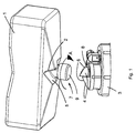
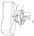
- a replacement ink or solvent container 1 for attachment to an ink jet printer ink system (see Figure 3), has a connector 7 which has two recesses 2 formed around its periphery.
- the container 1 may be connected (as shown in Figure 2) to an adapter 3, which is connected to an ink system of the ink jet printer.
- the adapter 3 is either an integral part of the ink jet printer or a separate, detachable, unit thereby enabling attachment to ports of the ink system of various ink jet printers to allow the containers to be fitted to a range of printers, in which case it may include a screw-threaded portion 3'.
- the adapter 3 has two protrusions 4 adapted to correspond with the recesses 2 of the ink container 1 when the container 1 and adapter 3 are fully connected. Between the protrusions 4, the adapter 3 has a receiving hole 8 adapted to receive a plug-in portion 9 of the connector 7. An 'O'-ring seal in the hole 8 ensures a sealed connection when the adapter 3 and connector 7 are fully connected.
- the recesses 2 each have a cam follower surface 5 inclined to the centre axis of the connection and the protrusions 4 each have a corresponding angular helical cam surface 6 similarly inclined to the centre axis of the connection.
- the connector 7 is pushed, axially, into the adapter 3 to form a sealed connection between the container 1 and the ink system.
- the container's ink or solvent may then flow through the connection to top-up the fluid of the ink system on demand.
- the container 1 When empty, the container 1 may be removed from the adapter 3 by rotation in the direction of arrow A. This causes the surfaces 5 and 6 to slide over one another and, due to the incline of the surfaces 5 and 6, the protrusions 4 are displaced from the recesses 2 and the container 1 is smoothly urged away from the adapter 3, breaking the sealed connection between the plug-in portion 9 of the connector 7 and the hole 8 of the adapter 3.
- An advantage of this arrangement is that, in comparison to pulling the container 1 from the port 3 to break the seal in a conventional manner, a rotating motion may be applied to the container in a restrained and a controlled manner, allowing less force to be used in removal and providing for clean and easy handling of containers 1.
- the specific positioning and shape of the protrusions 4 and recesses 2 ensures attachment of only containers 1 specifically designed to be attached to the corresponding adapter 3 as the recesses 2 must fully accommodate the protrusions 4 for a connection to be formed.
- the hand of the inclined surfaces 5 and 6 about the axis of connection is clockwise for replacement solvent containers and adapters for solvent ports, and the hand is anticlockwise for replacement ink containers and adapters for ink ports, erroneous connection of solvent and ink containers may be prevented.
- the printhead 20 of the printer has a nozzle 21 to which ink is fed from a feed line port 23 around the sides of the piezoelectric drive rod (not shown) which fits in the bore 24.
- the actuator (not shown) of a printhead valve 22 (solenoid-operated) slides in a second bore 25 to open and close the nozzle 21.
- a bleed line port 26 allows ink to be bled from the printhead.
- the ink system 10 of the exemplified printer of the present invention includes flow lines 11-14 which are connected a to the printhead 20 to provide, respectively, a flush line, a bleed line, a feed line and a gutter line.
- the solenoid-operated valve 22 which controls the flow of ink, in use, from the feed line 13 to the nozzle 21.
- ink is withdrawn from an ink reservoir 30 by means of one side of a dual circuit pump 31 and is passed along the feed line 13.
- the feed line 13 is positioned a solenoid-operated feed valve 34.
- the bleed line 12 has a pressure transducer 33 associated with it to measure the pressure of ink at the printhead (the bleed line is a static line and there is thus no pressure drop between the printhead 20 and the transducer 33).
- the ink passes into the printhead through a filter 35 and thence through the valve 22 and the nozzle 21.
- Ink droplets which are not used for printing are directed to the gutter line 14 and pass through a filter 41 and then back through the other side of the dual circuit pump 31 to the reservoir 30.
- a replaceable ink cartridge 1 (as described above) provides, via a dip tube system 37, for topping up of the reservoir 30.
- the dual circuit pump 31 also supplies ink to a line 42, through a filter 43, to a jet pump 50.
- the flow line 42 is connected to the primary inlet 51 of the jet pump 50 which provides, through an orifice 52, a flow of primary or entraining ink to an outlet 53.
- the outlet 53 provides ink into a flow line 44 from which it is fed selectively on operation of a solenoid-operated valve 45, either through a flow line 46 to a viscometer 47 or else through a pressure release valve 48, to a return line 49 into the reservoir 30.
- a pressure relief valve 38 provides over-pressure protection against high pressure in the output from the pump 31.
- the primary flow of ink through the jet pump 50 is used to entrain a flow of solvent which acts as a flushing fluid, the solvent being supplied through a secondary port 54 in the conventional manner of a jet pump.
- Solvent is supplied to the inlet 54 from a solvent reservoir 61 via the flush line 11 and a solenoid-operated solvent flush valve 81, into the printhead, through the bleed line 12, and a solenoid operated bleed valve 71.
- a renewable solvent cartridge 1 (of the type described above) maintains the level of solvent in the reservoir 61 via a dip tube system 65.
- additional solvent is supplied as necessary depending upon the viscosity determined in the viscometer 47, by selective operation of the valve 63, the added solvent being mixed with the ink flow through the gutter line 14 and passed back to the reservoir 30.
- the bleed line 12 joins to the jet pump 50 through a solenoid-operated bleed valve 71 which, in normal use remains closed.
- the solenoid-operated flush valve 81 connects the flush line 11 to the solvent reservoir 61 and is also closed during normal operation.
- a solenoid operated secondary flush valve 91 connects the outlet of the dual circuit pump 31 with the bleed line between the bleed valve 71 and the printhead 20. This again is normally closed during operation of the printer.
- solvent is flushed through the printhead to remove residual ink and this is achieved as follows.
- the printhead valve 22 is closed so that ink is no longer supplied to the nozzle 21.
- Ink continues to circulate from the reservoir 30 through the pump 31, via the jet pump 50 and the return line 49.
- the feed valve 34 is then closed and the flush valve 81 and bleed valve 71 are opened so that solvent from the reservoir 61 can be drawn, via a filter 67, under the negative pressure provided by the jet pump 50 in the bleed line 12, through the flush line 11, the printhead 20 and the bleed line 12.
- the flush valve 81 and bleed valve 71 are closed.
- the secondary flush valve 91 is opened briefly to pressurise the printhead and then the printhead valve 22 is also opened so that ink supplied to the bleed line 12 through the secondary flush valve 91 pushes solvent in the bleed line through the printhead valve 22 and out through the nozzle 21. Thus, solvent is flushed through all the necessary parts of the printhead 20. The printer can then be shut down until required again.
- the flush valve 81 and the printhead valve 22 may be pulsed open and closed during the flushing procedure in order to reduce the amount of solvent used.
- the jet pump 50 acts to provide a source of negative pressure to draw solvent through the flush line 11 and into the bleed line 12, avoiding the need for a separate flushing pump and the arrangement also improves the cleaning of the gun body. Furthermore, the vacuum produced by the jet pump enables the gutter vacuum to be maintained during the flushing procedure which, in turn, eliminates the possibility of ink running out of the gutter as the printer is shut down.
- Pressurising the secondary flush valve 91 produces a weaker dilution of ink and solvent to be passed through the nozzle, due to the fact that the bleed line is used to return the flushed fluid to the ink reservoir 30 during cleaning, thus improving the cleaning of the nozzle.
Landscapes
- Ink Jet (AREA)
Claims (10)
- Ein Behälter (1) zum Nachfüllen von Druckerfarbe/Tinte oder Lösemittel in einem Druckerfarbsystem eines Tintenstrahldruckers, wobei der Behälter (1) aufweist
einen Steckverbinder (7) zur Anbringung an einem damit passenden Adapter (3) an dem Druckerfarbsystem entlang einer Achse, durch die Fluid innerhalb des Behälters (1) an das Druckerfarbsystem überführt werden kann, und dadurch gekennzeichnet, daß
benachbart zu dem Verbinder (7) eine Kurven- oder Nockenfläche (5) angeordnet ist, um den Verbinder (7) sich von dem damit zusammenpassenden Verbinder bei Drehung des Behälters (1) in einer ersten Richtung um die Achse lösen zu lassen. - Ein Adapter (3) zum Verbinden des Behälters (1) nach Anspruch 1 mit einem Druckerfarbsystem eines Tintenstrahldruckers, wobei der Adapter (3) aufweist
einen Verbinder zum Zusammenpassen mit dem entsprechenden Steckverbinder (7) des Behälters (1) und durch den Fluid von innerhalb des Behälters (1) an das Druckerfarbsystem geleitet werden kann, und dadurch gekennzeichnet, daß
eine Kurven- oder Nockenfläche (6), zum Angriff an der Nockenfläche (5) des Behälters (1) angeordnet ist, um das Lösen des Behälterverbinders (7) von dem Adapter (3) bei Drehung des Verbinders (7) in der ersten Richtung zu bewirken. - Der Adapter (3) nach Anspruch 2, weiter umfassend einen mit Schraubgewinde versehenen Verbinder (3') zur Verbindung mit einem Fluidreservoir des Druckerfarbsystems.
- Ein Behälter (1) nach Anspruch 1, wobei die Nockenoberfläche eine ringförmige Schraubenwendel-Nockenfläche ist, die um den jeweiligen Verbinder herum angeordnet ist.
- Ein Behälter (1) nach Anspruch 1, wobei die Nockenoberfläche eine Nockenstößeloberfläche (5) ist.
- Ein Adapter (3) nach Anspruch 2, wobei die Nockenoberfläche eine ringförmige Schraubenwendel-Nockenoberfläche (6) ist, die um den jeweiligen Verbinder herum angeordnet ist.
- Ein Adapter (3) nach Anspruch 2, wobei die Nockenoberfläche eine Nockenstößeloberfläche ist.
- Ein Tintenstrahldrucker-Druckerfarbsystem mit dem Behälter (1) nach einem der Ansprüche 1, 4 oder 5 und dem Adapter gemäß einem der Ansprüche 2, 3, 6 oder 7.
- Ein Tintenstrahldrucker-Druckerfarbsystem nach Anspruch 8, mit separaten Nachfüll-Druckerfarb- und Lösemittel-Behältern (1) und entsprechenden Adaptern (3), wobei der jeweilige Behälter (1) und Adapter-Verbinder (3) so ausgebildet sind, daß sie die Anbringung eines entsprechenden Behälters (1) an einem jeweils anderen Adapter (3) verhindern.
- Ein Tintenstrahldrucker-Druckerfarbsystem nach Anspruch 9, wobei die Nockenoberflächen des Behälters (1) oder der Adapter-Verbinder (3) Schraubenwendel-Nockenflächen in entgegengesetzter Drehrichtung sind.
Priority Applications (1)
| Application Number | Priority Date | Filing Date | Title |
|---|---|---|---|
| DE29824774U DE29824774U1 (de) | 1998-01-09 | 1998-12-11 | Verbindung für Austausch-Fluidbehälter für Tintenstrahldrucker |
Applications Claiming Priority (2)
| Application Number | Priority Date | Filing Date | Title |
|---|---|---|---|
| GB9800496 | 1998-01-09 | ||
| GBGB9800496.3A GB9800496D0 (en) | 1998-01-09 | 1998-01-09 | Connection for replacement fluid containers for ink jet printers |
Publications (2)
| Publication Number | Publication Date |
|---|---|
| EP0928693A1 EP0928693A1 (de) | 1999-07-14 |
| EP0928693B1 true EP0928693B1 (de) | 2003-04-02 |
Family
ID=10825090
Family Applications (1)
| Application Number | Title | Priority Date | Filing Date |
|---|---|---|---|
| EP98310171A Expired - Lifetime EP0928693B1 (de) | 1998-01-09 | 1998-12-11 | Verbindung für Auswechselflüssigkeitsbehälter in Tintenstrahldruckern |
Country Status (6)
| Country | Link |
|---|---|
| US (1) | US6158854A (de) |
| EP (1) | EP0928693B1 (de) |
| JP (1) | JPH11245431A (de) |
| CN (1) | CN1100675C (de) |
| DE (1) | DE69812866T2 (de) |
| GB (1) | GB9800496D0 (de) |
Families Citing this family (15)
| Publication number | Priority date | Publication date | Assignee | Title |
|---|---|---|---|---|
| FR2775809B1 (fr) * | 1998-03-09 | 2002-06-14 | Finaluxe | Bracelet comportant des moyens pour son identification |
| US6935730B2 (en) * | 2000-04-03 | 2005-08-30 | Unicorn Image Products Co. Ltd. Of Zhuhai | One-way valve, valve unit assembly, and ink cartridge using the same |
| US20050243147A1 (en) * | 2000-10-12 | 2005-11-03 | Unicorn Image Products Co. Ltd. | Ink cartridge having bellows valve, ink filling method and apparatus used thereof |
| JP4585797B2 (ja) * | 2004-06-07 | 2010-11-24 | キヤノン株式会社 | 液体供給装置 |
| GB0425079D0 (en) | 2004-11-13 | 2004-12-15 | Videojet Technologies Inc | A tool used for assisting the removal from an ink jet printer of a container used to supply fluid to the printer |
| US7621426B2 (en) * | 2004-12-15 | 2009-11-24 | Joseph Kanfer | Electronically keyed dispensing systems and related methods utilizing near field frequency response |
| US7510261B2 (en) * | 2005-10-11 | 2009-03-31 | Silverbrook Research Pty Ltd | Printhead assembly comprising ink reservoir containing cleaning liquid |
| GB0608762D0 (en) * | 2006-05-04 | 2006-06-14 | Domino Printing Sciences Plc | Improvements in or relating to continuous inkjet printers |
| GB0720288D0 (en) * | 2007-10-12 | 2007-11-28 | Videojet Technologies Inc | Container and method for liquid storage and dispensing |
| CN102941737B (zh) * | 2007-10-12 | 2014-12-10 | 录象射流技术公司 | 喷墨模组 |
| US8590742B2 (en) * | 2008-07-26 | 2013-11-26 | Hewlett-Packard Development Company, L.P. | Fluid supply contact |
| WO2015111244A1 (ja) | 2014-01-27 | 2015-07-30 | 株式会社日立産機システム | カートリッジ式インクジェット記録装置 |
| CN106142847B (zh) * | 2015-04-21 | 2018-04-03 | 研能科技股份有限公司 | 连续供墨系统 |
| GB2575986A (en) | 2018-07-30 | 2020-02-05 | Domino Uk Ltd | Solvent supply tube arrangement |
| CN109910441B (zh) * | 2019-02-22 | 2020-07-14 | 深圳市越达彩印科技有限公司 | 一种用于高温数码玻璃打印机上的预防喷头堵头的方法 |
Family Cites Families (13)
| Publication number | Priority date | Publication date | Assignee | Title |
|---|---|---|---|---|
| US4211439A (en) * | 1978-07-26 | 1980-07-08 | Moldestad Jon P | Safety device for hose connections |
| US4665960A (en) * | 1985-03-04 | 1987-05-19 | Cajon Company | Coded coupling |
| JPS61284445A (ja) * | 1985-06-11 | 1986-12-15 | Nec Corp | インクジエツトプリンタのインクタンク装置 |
| US4708370A (en) * | 1985-11-14 | 1987-11-24 | Toddco | Recreational vehicle discharge pipe coupler |
| GB9205870D0 (en) * | 1992-03-18 | 1992-04-29 | Willett Int Ltd | Replenishment of reservoirs |
| US5606988A (en) * | 1994-02-04 | 1997-03-04 | Hewlett -Packard Company | Connector assembly for ink cartridge |
| US5673073A (en) * | 1994-09-29 | 1997-09-30 | Hewlett-Packard Company | Syringe for filling print cartridge and establishing correct back pressure |
| EP0704309A3 (de) * | 1994-09-29 | 1998-01-07 | Hewlett-Packard Company | Verfahren und Einrichtung zur Tintenwiederauffüllung einer Tintenpatrone |
| US6203147B1 (en) * | 1994-12-22 | 2001-03-20 | Hewlett-Packard Company | Electrical and fluidic interface for an ink supply |
| US5646664A (en) * | 1995-01-18 | 1997-07-08 | Hewlett-Packard Company | Ink container valving |
| KR100208924B1 (ko) * | 1995-08-22 | 1999-07-15 | 야스카와 히데아키 | 잉크제트 헤드 접속유닛 및 잉크제트 카트리지 및 그 조립방법 |
| US5732751A (en) * | 1995-12-04 | 1998-03-31 | Hewlett-Packard Company | Filling ink supply containers |
| CA2191636A1 (en) * | 1996-05-20 | 1997-11-21 | Norman Pawlowski, Jr. | Interlocking connector assembly |
-
1998
- 1998-01-09 GB GBGB9800496.3A patent/GB9800496D0/en not_active Ceased
- 1998-12-09 US US09/208,221 patent/US6158854A/en not_active Expired - Fee Related
- 1998-12-11 EP EP98310171A patent/EP0928693B1/de not_active Expired - Lifetime
- 1998-12-11 DE DE69812866T patent/DE69812866T2/de not_active Expired - Lifetime
- 1998-12-22 JP JP10364578A patent/JPH11245431A/ja active Pending
-
1999
- 1999-01-08 CN CN99101038A patent/CN1100675C/zh not_active Expired - Lifetime
Also Published As
| Publication number | Publication date |
|---|---|
| US6158854A (en) | 2000-12-12 |
| JPH11245431A (ja) | 1999-09-14 |
| GB9800496D0 (en) | 1998-03-04 |
| DE69812866T2 (de) | 2004-01-22 |
| CN1100675C (zh) | 2003-02-05 |
| EP0928693A1 (de) | 1999-07-14 |
| DE69812866D1 (de) | 2003-05-08 |
| CN1226480A (zh) | 1999-08-25 |
Similar Documents
| Publication | Publication Date | Title |
|---|---|---|
| EP0928693B1 (de) | Verbindung für Auswechselflüssigkeitsbehälter in Tintenstrahldruckern | |
| US6074042A (en) | Ink container having a guide feature for insuring reliable fluid, air and electrical connections to a printing system | |
| EP0976564B1 (de) | Dichtungselement für Flüssigkeitsbehälter | |
| DE69809933T2 (de) | Verfahren und vorrichtung zur sicherung eines tintenbehälters | |
| DE69807496T2 (de) | Elektrische zusammenschaltung für farbstoffbehälter | |
| US7556367B2 (en) | Ink delivery system and a method for replacing ink | |
| EP0908316B1 (de) | Tintenstrahldrucker | |
| JP6579193B2 (ja) | プリントヘッドアセンブリおよび流体相互接続システム | |
| EP0925937B1 (de) | Tintenzuführsystem, Spüleinrichtung und Verfahren | |
| EP3890983B1 (de) | Unterdruckrückgewinnung von druckmitteln | |
| US20220032634A1 (en) | Extraction reservoir-triggered fluid extraction | |
| DE29824774U1 (de) | Verbindung für Austausch-Fluidbehälter für Tintenstrahldrucker | |
| HK1032368B (en) | Replaceable ink container for providing ink to off-axis printing system |
Legal Events
| Date | Code | Title | Description |
|---|---|---|---|
| PUAI | Public reference made under article 153(3) epc to a published international application that has entered the european phase |
Free format text: ORIGINAL CODE: 0009012 |
|
| AK | Designated contracting states |
Kind code of ref document: A1 Designated state(s): DE FR GB IT |
|
| AX | Request for extension of the european patent |
Free format text: AL;LT;LV;MK;RO;SI |
|
| 17P | Request for examination filed |
Effective date: 19991213 |
|
| AKX | Designation fees paid |
Free format text: DE FR GB IT |
|
| GRAH | Despatch of communication of intention to grant a patent |
Free format text: ORIGINAL CODE: EPIDOS IGRA |
|
| GRAH | Despatch of communication of intention to grant a patent |
Free format text: ORIGINAL CODE: EPIDOS IGRA |
|
| GRAA | (expected) grant |
Free format text: ORIGINAL CODE: 0009210 |
|
| AK | Designated contracting states |
Designated state(s): DE FR GB IT |
|
| REG | Reference to a national code |
Ref country code: GB Ref legal event code: FG4D |
|
| REF | Corresponds to: |
Ref document number: 69812866 Country of ref document: DE Date of ref document: 20030508 Kind code of ref document: P |
|
| ET | Fr: translation filed | ||
| PLBE | No opposition filed within time limit |
Free format text: ORIGINAL CODE: 0009261 |
|
| STAA | Information on the status of an ep patent application or granted ep patent |
Free format text: STATUS: NO OPPOSITION FILED WITHIN TIME LIMIT |
|
| 26N | No opposition filed |
Effective date: 20040105 |
|
| REG | Reference to a national code |
Ref country code: FR Ref legal event code: PLFP Year of fee payment: 18 |
|
| REG | Reference to a national code |
Ref country code: FR Ref legal event code: PLFP Year of fee payment: 19 |
|
| REG | Reference to a national code |
Ref country code: FR Ref legal event code: PLFP Year of fee payment: 20 |
|
| PGFP | Annual fee paid to national office [announced via postgrant information from national office to epo] |
Ref country code: FR Payment date: 20171218 Year of fee payment: 20 |
|
| PGFP | Annual fee paid to national office [announced via postgrant information from national office to epo] |
Ref country code: GB Payment date: 20171227 Year of fee payment: 20 |
|
| PGFP | Annual fee paid to national office [announced via postgrant information from national office to epo] |
Ref country code: DE Payment date: 20171218 Year of fee payment: 20 |
|
| PGFP | Annual fee paid to national office [announced via postgrant information from national office to epo] |
Ref country code: IT Payment date: 20171221 Year of fee payment: 20 |
|
| REG | Reference to a national code |
Ref country code: DE Ref legal event code: R071 Ref document number: 69812866 Country of ref document: DE |
|
| REG | Reference to a national code |
Ref country code: GB Ref legal event code: PE20 Expiry date: 20181210 |
|
| PG25 | Lapsed in a contracting state [announced via postgrant information from national office to epo] |
Ref country code: GB Free format text: LAPSE BECAUSE OF EXPIRATION OF PROTECTION Effective date: 20181210 |