EP3597462A1 - Dispositif d'essieu de véhicule électrique et procédé de positionnement d'un couvercle de palier sur un boitier dans un dispositif d'essieu de véhicule électrique - Google Patents
Dispositif d'essieu de véhicule électrique et procédé de positionnement d'un couvercle de palier sur un boitier dans un dispositif d'essieu de véhicule électrique Download PDFInfo
- Publication number
- EP3597462A1 EP3597462A1 EP19186546.8A EP19186546A EP3597462A1 EP 3597462 A1 EP3597462 A1 EP 3597462A1 EP 19186546 A EP19186546 A EP 19186546A EP 3597462 A1 EP3597462 A1 EP 3597462A1
- Authority
- EP
- European Patent Office
- Prior art keywords
- housing
- joining areas
- bearing cover
- dimensional joining
- vehicle axle
- Prior art date
- Legal status (The legal status is an assumption and is not a legal conclusion. Google has not performed a legal analysis and makes no representation as to the accuracy of the status listed.)
- Granted
Links
- 238000000034 method Methods 0.000 title claims abstract description 15
- 230000005540 biological transmission Effects 0.000 claims description 20
- 238000011161 development Methods 0.000 description 11
- 230000018109 developmental process Effects 0.000 description 11
- 230000006978 adaptation Effects 0.000 description 2
- 230000015572 biosynthetic process Effects 0.000 description 1
Images


Classifications
-
- H—ELECTRICITY
- H02—GENERATION; CONVERSION OR DISTRIBUTION OF ELECTRIC POWER
- H02K—DYNAMO-ELECTRIC MACHINES
- H02K5/00—Casings; Enclosures; Supports
- H02K5/04—Casings or enclosures characterised by the shape, form or construction thereof
- H02K5/15—Mounting arrangements for bearing-shields or end plates
-
- B—PERFORMING OPERATIONS; TRANSPORTING
- B60—VEHICLES IN GENERAL
- B60K—ARRANGEMENT OR MOUNTING OF PROPULSION UNITS OR OF TRANSMISSIONS IN VEHICLES; ARRANGEMENT OR MOUNTING OF PLURAL DIVERSE PRIME-MOVERS IN VEHICLES; AUXILIARY DRIVES FOR VEHICLES; INSTRUMENTATION OR DASHBOARDS FOR VEHICLES; ARRANGEMENTS IN CONNECTION WITH COOLING, AIR INTAKE, GAS EXHAUST OR FUEL SUPPLY OF PROPULSION UNITS IN VEHICLES
- B60K1/00—Arrangement or mounting of electrical propulsion units
-
- F—MECHANICAL ENGINEERING; LIGHTING; HEATING; WEAPONS; BLASTING
- F16—ENGINEERING ELEMENTS AND UNITS; GENERAL MEASURES FOR PRODUCING AND MAINTAINING EFFECTIVE FUNCTIONING OF MACHINES OR INSTALLATIONS; THERMAL INSULATION IN GENERAL
- F16C—SHAFTS; FLEXIBLE SHAFTS; ELEMENTS OR CRANKSHAFT MECHANISMS; ROTARY BODIES OTHER THAN GEARING ELEMENTS; BEARINGS
- F16C35/00—Rigid support of bearing units; Housings, e.g. caps, covers
-
- H—ELECTRICITY
- H02—GENERATION; CONVERSION OR DISTRIBUTION OF ELECTRIC POWER
- H02K—DYNAMO-ELECTRIC MACHINES
- H02K5/00—Casings; Enclosures; Supports
- H02K5/04—Casings or enclosures characterised by the shape, form or construction thereof
- H02K5/16—Means for supporting bearings, e.g. insulating supports or means for fitting bearings in the bearing-shields
-
- H—ELECTRICITY
- H02—GENERATION; CONVERSION OR DISTRIBUTION OF ELECTRIC POWER
- H02K—DYNAMO-ELECTRIC MACHINES
- H02K7/00—Arrangements for handling mechanical energy structurally associated with dynamo-electric machines, e.g. structural association with mechanical driving motors or auxiliary dynamo-electric machines
- H02K7/10—Structural association with clutches, brakes, gears, pulleys or mechanical starters
- H02K7/116—Structural association with clutches, brakes, gears, pulleys or mechanical starters with gears
-
- B—PERFORMING OPERATIONS; TRANSPORTING
- B60—VEHICLES IN GENERAL
- B60K—ARRANGEMENT OR MOUNTING OF PROPULSION UNITS OR OF TRANSMISSIONS IN VEHICLES; ARRANGEMENT OR MOUNTING OF PLURAL DIVERSE PRIME-MOVERS IN VEHICLES; AUXILIARY DRIVES FOR VEHICLES; INSTRUMENTATION OR DASHBOARDS FOR VEHICLES; ARRANGEMENTS IN CONNECTION WITH COOLING, AIR INTAKE, GAS EXHAUST OR FUEL SUPPLY OF PROPULSION UNITS IN VEHICLES
- B60K1/00—Arrangement or mounting of electrical propulsion units
- B60K2001/001—Arrangement or mounting of electrical propulsion units one motor mounted on a propulsion axle for rotating right and left wheels of this axle
-
- B—PERFORMING OPERATIONS; TRANSPORTING
- B60—VEHICLES IN GENERAL
- B60Y—INDEXING SCHEME RELATING TO ASPECTS CROSS-CUTTING VEHICLE TECHNOLOGY
- B60Y2410/00—Constructional features of vehicle sub-units
- B60Y2410/10—Housings
-
- B—PERFORMING OPERATIONS; TRANSPORTING
- B60—VEHICLES IN GENERAL
- B60Y—INDEXING SCHEME RELATING TO ASPECTS CROSS-CUTTING VEHICLE TECHNOLOGY
- B60Y2410/00—Constructional features of vehicle sub-units
- B60Y2410/102—Shaft arrangements; Shaft supports, e.g. bearings
-
- F—MECHANICAL ENGINEERING; LIGHTING; HEATING; WEAPONS; BLASTING
- F16—ENGINEERING ELEMENTS AND UNITS; GENERAL MEASURES FOR PRODUCING AND MAINTAINING EFFECTIVE FUNCTIONING OF MACHINES OR INSTALLATIONS; THERMAL INSULATION IN GENERAL
- F16C—SHAFTS; FLEXIBLE SHAFTS; ELEMENTS OR CRANKSHAFT MECHANISMS; ROTARY BODIES OTHER THAN GEARING ELEMENTS; BEARINGS
- F16C2380/00—Electrical apparatus
- F16C2380/26—Dynamo-electric machines or combinations therewith, e.g. electro-motors and generators
-
- Y—GENERAL TAGGING OF NEW TECHNOLOGICAL DEVELOPMENTS; GENERAL TAGGING OF CROSS-SECTIONAL TECHNOLOGIES SPANNING OVER SEVERAL SECTIONS OF THE IPC; TECHNICAL SUBJECTS COVERED BY FORMER USPC CROSS-REFERENCE ART COLLECTIONS [XRACs] AND DIGESTS
- Y02—TECHNOLOGIES OR APPLICATIONS FOR MITIGATION OR ADAPTATION AGAINST CLIMATE CHANGE
- Y02T—CLIMATE CHANGE MITIGATION TECHNOLOGIES RELATED TO TRANSPORTATION
- Y02T10/00—Road transport of goods or passengers
- Y02T10/60—Other road transportation technologies with climate change mitigation effect
- Y02T10/64—Electric machine technologies in electromobility
Definitions
- the invention relates to an electric vehicle axle device for a motor vehicle.
- the invention further relates to a method for positioning a bearing cover relative to a housing in an electrical vehicle axle device for a motor vehicle.
- Electrical vehicle axle devices for motor vehicles conventionally have an electrical machine, power electronics for controlling the electrical machine and a gearbox coupled to the electrical machine.
- the electrical vehicle axle device has a housing in which at least the electrical machine and the transmission are accommodated.
- the transmission has a plurality of bearings, which are positioned by a positioning device relative to a bearing cover fastened to the housing.
- the positioning device is formed by a pair of dowel pins or dowel pins, which are arranged as desired in an edge region of the housing and protrude from the housing at a perpendicular angle.
- the cover to be placed on the housing has corresponding bores into which the dowel pins or dowel pins of the housing can be inserted.
- DE 10 2013 204 776 A1 discloses an electric vehicle axle device having at least one vehicle axle to which vehicle wheels are attachable, and wherein the electric vehicle axle device has a transmission connected to the vehicle axle. Furthermore, the vehicle axle device has an electric motor, which is coupled to the transmission, for transmitting a torque to the vehicle axle and the vehicle wheels connected to the vehicle axle. In addition, the electrical vehicle axle device has power electronics, the power electronics having an inverter, which is connected to the electric motor, for supplying the electric motor with electrical energy.
- the present invention provides an electrical vehicle axle device for a motor vehicle, with an electrical machine, with a transmission coupled to the electrical machine and with a housing in which at least the electrical machine and the transmission are accommodated, the transmission having a plurality of bearings, which are positioned by a positioning device to a bearing cover fastened to the housing, the positioning device having first three-dimensional joining areas formed on a surface of the housing and second three-dimensional joining areas formed on an inside of the bearing cover, the first three-dimensional joining areas of the housing and the second three-dimensional joining areas of the bearing cover are joined together positively.
- the present invention further provides a method for positioning a bearing cap relative to a housing in an electric vehicle axle device for a motor vehicle.
- the method comprises providing an electrical machine, power electronics for controlling the electrical machine, a transmission coupled to the electrical machine, and a housing in which at least the electrical machine and the transmission are accommodated.
- the method further comprises positioning a plurality of bearings of the transmission to a bearing cover fastened to the transmission by means of a positioning device.
- the method further comprises providing the positioning device with first three-dimensional joining areas formed on a surface of the housing and second three-dimensional joining areas formed on an inside of the bearing cover.
- the method also includes a positive connection of the first three-dimensional joining areas of the housing and the second three-dimensional joining areas of the bearing cover.
- An idea of the present invention is to provide the positioning device on the surface of the housing in the form of first three-dimensional joining areas and an inside of the bearing cover by second three-dimensional joining areas, the first three-dimensional joining areas of the housing on the bottom thereof and the second three-dimensional joining areas of the bearing cover are positively joined to enable improved positioning or centering of the bearings, since the respective joining areas of the housing and the bearing cover now have surface contact or ring surface contact compared to a conventional point or line contact.
- lid and pot seat which due to its geometry forms a radial form fit and is designed in such a way that its center forms a new axis that can be aligned with, for example, a motor axis or a bearing axis on the lid, a more precise axis-accurate positioning of the bearings be made possible.
- the first three-dimensional joining areas formed on the surface of the housing are each convex, and the second three-dimensional joining areas formed on the inside of the bearing cover are each concave.
- the convex and concave design of the respective joining surfaces thus advantageously enables surface contact between the joining regions of the housing and the cover, and thus exact, axially accurate positioning of the bearings.
- first three-dimensional joining areas formed on the surface of the housing are each concave
- second three-dimensional joining areas formed on the inside of the bearing cover are each convex.
- At least one of the first three-dimensional joining regions formed on the surface of the housing is convex and at least one further of the first three-dimensional joining regions formed on the surface of the housing is concave.
- At least one of the second three-dimensional joining areas formed on the inside of the bearing cover is convex and at least one of the other on the The inside of the bearing cover formed second three-dimensional joining areas is concave.
- This mixing arrangement too, by providing both convex and concave joining areas on, for example, the inside of the bearing cover, can advantageously achieve an optimal adaptation of the respective joining areas to a component geometry of the bearing cover.
- three first three-dimensional joining areas are formed on the surface of the housing and three second three-dimensional joining areas are formed on the inside of the bearing cover.
- a respective one of the first convex three-dimensional joining regions formed on the surface of the housing has a conical projection and / or a respective one of the first three-dimensional joining regions formed on the surface of the housing has a conical projection Has recess.
- a respective one of the second convex three-dimensional joining areas formed on the inside of the bearing cover has a conical projection and / or a respective one of the second concave three-dimensional joining areas formed on the inside of the bearing cover has a tapering Has recess.
- the first three-dimensional joining areas formed on the surface of the housing are arranged on a housing edge and / or a housing wall arranged adjacent to the plurality of bearings. Such an arrangement of the three-dimensional joining areas enables a spatial and structurally optimally adapted distribution of the respective joining areas on the housing and on the bearing cover.
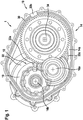
- Fig. 1 shows a side view of an electric vehicle axle device with removed bearing cover according to a preferred embodiment of the invention.
- the electric vehicle axle device 1 has an electric machine 10. Furthermore, the electrical vehicle axle device 10 has a transmission 12 coupled to the electrical machine 10. Furthermore, the electrical vehicle axle device 1 has a housing 14, in which at least the electrical machine 10 and the transmission 12 are accommodated.
- the transmission 12 has a plurality of bearings 16a, 16b.
- the plurality of bearings 16a, 16b are attached to the housing 14 by a positioning device 18 (in Fig. 1 bearing cover (not shown) can be positioned.
- the positioning device 18 has first three-dimensional joining areas 22a, 22b, 22c formed on a surface 14a of the housing 14 and on an inside of the (in Fig. 1 not shown) formed bearing cap, second three-dimensional joining areas.
- the first three-dimensional joining areas 22a, 22b, 22c of the housing 14 and the second three-dimensional joining areas of the bearing cover can be joined together in a form-fitting manner.
- first three-dimensional joining regions 22a, 22b, 22c on the surface 14a of the housing 14 and on the inside of the (in Fig. 1 bearing cover (not shown) also formed three second three-dimensional joining areas. Furthermore, the first three-dimensional joining regions 22a, 22b, 22c formed on the surface 14a of the housing 14 are arranged on a housing edge 30 and on a housing wall 32 arranged adjacent to the plurality of bearings 16a, 16b.
- first three-dimensional joining areas 22a, 22b, 22c can be arranged, for example, only in the area of the housing edge 30 or only or only in the area of the housing wall 32.
- Reference numeral 34 denotes a drive shaft of the vehicle electric axle apparatus 1.
- Fig. 2 shows a cross-sectional view of the bearing cap attached to a housing of the electric vehicle axle device according to a first embodiment of the invention.
- first three-dimensional joining regions 22a formed on the surface 14a of the housing 14 is convex in the present embodiment.
- An example of the second three-dimensional joining areas 24a formed on the inside 20a of the bearing cover 20 is concave in the present embodiment and is joined to the first three-dimensional joining area 22a of the housing 14 in a form-fitting manner.
- a respective one of the first convex three-dimensional joining areas 22a formed on the surface 14a of the housing 14 has a conical projection 26. Furthermore, it is provided according to the present embodiment that the on the inside 20a of the Bearing cover 20 formed second three-dimensional joining area 24a has a tapered recess 28.
- Fig. 3 shows a cross-sectional view of the bearing cap attached to a housing of the electric vehicle axle device according to a second embodiment of the invention.
- the first three-dimensional joining areas 22a are each concave. Furthermore, it is provided that the second three-dimensional joining areas 24a formed on the inside 20a of the bearing cover 20 are each convex and are positively joined to the first three-dimensional joining area 22a of the housing 14.
- a respective one of the first convex three-dimensional joining areas 24a formed on the inside 20a of the bearing cover 20 has a conical projection 26a. Furthermore, according to the present embodiment it is provided that the second three-dimensional joining area 24a formed on the inside 20a of the bearing cover 20 has a conical recess 28a.
- the convex second three-dimensional joining areas 24a of the bearing cover 20 have a radius R.
- Fig. 4 shows a flowchart of a method for positioning the bearing cover to the housing in the electric vehicle axle device for the motor vehicle according to the first and second embodiment of the invention.
- the method comprises providing S1 an electrical machine, power electronics for controlling the electrical machine, a transmission coupled to the electrical machine and a housing in which at least the electrical machine and the transmission are accommodated.
- the method further comprises positioning S2 a plurality of bearings of the transmission to a bearing cover fastened to the transmission by means of a positioning device.
- the method also includes providing S3 the positioning device with first three-dimensional joining areas formed on a surface of the housing and second three-dimensional joining areas formed on an inside of the bearing cover.
- the method also includes a positive connection S4 of the first three-dimensional joining areas of the housing and the second three-dimensional joining areas of the bearing cover.
- a shape, dimension and / or a nature of the components of the electrical vehicle axle device 1 can be changed.
Landscapes
- Engineering & Computer Science (AREA)
- Power Engineering (AREA)
- Mechanical Engineering (AREA)
- General Engineering & Computer Science (AREA)
- Chemical & Material Sciences (AREA)
- Combustion & Propulsion (AREA)
- Transportation (AREA)
- General Details Of Gearings (AREA)
Applications Claiming Priority (1)
| Application Number | Priority Date | Filing Date | Title |
|---|---|---|---|
| DE102018211938.4A DE102018211938A1 (de) | 2018-07-18 | 2018-07-18 | Elektrische Fahrzeugachsenvorrichtung und Verfahren zum Positionieren eines Lagerdeckels zu einem Gehäuse in einer elektrischen Fahrzeugachsenvorrichtung |
Publications (2)
| Publication Number | Publication Date |
|---|---|
| EP3597462A1 true EP3597462A1 (fr) | 2020-01-22 |
| EP3597462B1 EP3597462B1 (fr) | 2023-04-19 |
Family
ID=67314670
Family Applications (1)
| Application Number | Title | Priority Date | Filing Date |
|---|---|---|---|
| EP19186546.8A Active EP3597462B1 (fr) | 2018-07-18 | 2019-07-16 | Dispositif d'essieu de véhicule électrique |
Country Status (2)
| Country | Link |
|---|---|
| EP (1) | EP3597462B1 (fr) |
| DE (1) | DE102018211938A1 (fr) |
Cited By (1)
| Publication number | Priority date | Publication date | Assignee | Title |
|---|---|---|---|---|
| EP4246016A1 (fr) | 2022-03-16 | 2023-09-20 | Valeo eAutomotive Germany GmbH | Boîte de vitesses avec alignement amélioré des parties de boîtier |
Citations (6)
| Publication number | Priority date | Publication date | Assignee | Title |
|---|---|---|---|---|
| EP0471876A1 (fr) * | 1990-08-23 | 1992-02-26 | Siemens Aktiengesellschaft | Unité d'entraînement à moteur-réducteur, notamment entraînement de lève-glaces pour véhicule automobile |
| DE102013204776A1 (de) | 2013-03-19 | 2014-09-25 | Zf Friedrichshafen Ag | Getriebe für ein Kraftfahrzeug |
| US20150076972A1 (en) * | 2012-04-20 | 2015-03-19 | Ipgate Ag | Bearing arrangement in an axial drive |
| DE102014217125A1 (de) * | 2014-08-28 | 2016-03-03 | Robert Bosch Gmbh | Startvorrichtung für eine Brennkraftmaschine |
| DE102015226755A1 (de) * | 2015-12-28 | 2017-06-29 | Robert Bosch Gmbh | Elektromotor für Stellantriebe in Kraftfahrzeugen und Getriebe-Antriebseinrichtung |
| JP6315953B2 (ja) * | 2013-01-18 | 2018-04-25 | 株式会社ミツバ | 電動モータ及び電動ポンプ |
Family Cites Families (1)
| Publication number | Priority date | Publication date | Assignee | Title |
|---|---|---|---|---|
| JP3622878B2 (ja) * | 1997-04-17 | 2005-02-23 | アイシン・エィ・ダブリュ株式会社 | 電気自動車用駆動装置 |
-
2018
- 2018-07-18 DE DE102018211938.4A patent/DE102018211938A1/de active Pending
-
2019
- 2019-07-16 EP EP19186546.8A patent/EP3597462B1/fr active Active
Patent Citations (6)
| Publication number | Priority date | Publication date | Assignee | Title |
|---|---|---|---|---|
| EP0471876A1 (fr) * | 1990-08-23 | 1992-02-26 | Siemens Aktiengesellschaft | Unité d'entraînement à moteur-réducteur, notamment entraînement de lève-glaces pour véhicule automobile |
| US20150076972A1 (en) * | 2012-04-20 | 2015-03-19 | Ipgate Ag | Bearing arrangement in an axial drive |
| JP6315953B2 (ja) * | 2013-01-18 | 2018-04-25 | 株式会社ミツバ | 電動モータ及び電動ポンプ |
| DE102013204776A1 (de) | 2013-03-19 | 2014-09-25 | Zf Friedrichshafen Ag | Getriebe für ein Kraftfahrzeug |
| DE102014217125A1 (de) * | 2014-08-28 | 2016-03-03 | Robert Bosch Gmbh | Startvorrichtung für eine Brennkraftmaschine |
| DE102015226755A1 (de) * | 2015-12-28 | 2017-06-29 | Robert Bosch Gmbh | Elektromotor für Stellantriebe in Kraftfahrzeugen und Getriebe-Antriebseinrichtung |
Cited By (1)
| Publication number | Priority date | Publication date | Assignee | Title |
|---|---|---|---|---|
| EP4246016A1 (fr) | 2022-03-16 | 2023-09-20 | Valeo eAutomotive Germany GmbH | Boîte de vitesses avec alignement amélioré des parties de boîtier |
Also Published As
| Publication number | Publication date |
|---|---|
| EP3597462B1 (fr) | 2023-04-19 |
| DE102018211938A1 (de) | 2020-01-23 |
Similar Documents
| Publication | Publication Date | Title |
|---|---|---|
| EP0666634B1 (fr) | Ensemble moteur à combustion et générateur électrique | |
| EP2308153B1 (fr) | Procédé de fabrication d'une machine électrique et machine électrique pour véhicule hybride | |
| WO2016055322A1 (fr) | Dispositif de transmission | |
| EP3373421B1 (fr) | Unité de boîtier pour une machine électrique | |
| DE102011050094A1 (de) | Rotor für eine drehende elektrische Maschine | |
| DE102016205115A1 (de) | Getriebevorrichtung | |
| DE102018007644A1 (de) | Statorgehäuse, stator und drehende elektrische maschine | |
| EP3480929A1 (fr) | Carter refroidi pour le stator d'entraînement direct | |
| DE102018218181A1 (de) | Differentialeinrichtung | |
| DE2449072A1 (de) | Wirbelstrombremse | |
| DE102018203366A1 (de) | Elektrische Fahrzeugachsenvorrichtung und Verfahren zum Betreiben einer elektrischen Fahrzeugachsenvorrichtung | |
| DE102020205329A1 (de) | Kühlmechanismus für einen elektrischen fahrzeugmotor | |
| DE102015113509A1 (de) | Freitragender Stator | |
| DE102012216298A1 (de) | Winkelgetriebe | |
| EP3597462A1 (fr) | Dispositif d'essieu de véhicule électrique et procédé de positionnement d'un couvercle de palier sur un boitier dans un dispositif d'essieu de véhicule électrique | |
| DE102015016584A1 (de) | Verfahren zum Herstellen eines Stators und Stator | |
| DE102017122908A1 (de) | Segmentierter geschalteter Reluktanzmotor für die Kraftstrangelektrifizierung | |
| DE102018201822A1 (de) | Elektrisches Antriebssystem für ein elektrisch betriebenes Fahrzeug und Verfahren zum Herstellen eines elektrischen Antriebssystems für ein elektrisch betriebenes Fahrzeug | |
| DE102014115196A1 (de) | System und Verfahren zur zusammengefassten Drehmomentübertragung und Rotationsdichtung | |
| DE102012014950A1 (de) | Gehäuse für ein Ausgleichsgetriebe sowie Ausgleichsgetriebe für einen Kraftwagen | |
| DE102018210158A1 (de) | Baueinheit aus einer elektrischen Maschine und einem Tragelement | |
| DE112020004675T5 (de) | Rotor, traktionsmotor und verfahren zum herstellen des rotors | |
| DE102016013493A1 (de) | Antriebswellenbaugruppe und Verfahren für ihre Herstellung | |
| DE102016010224A1 (de) | Elektrische Maschine für ein Kraftfahrzeug, Herstellungsverfahren und Stanzwerkzeug | |
| WO2020259868A1 (fr) | Motoréducteur, en particulier série de motoréducteurs, avec partie d'adaptation |
Legal Events
| Date | Code | Title | Description |
|---|---|---|---|
| PUAI | Public reference made under article 153(3) epc to a published international application that has entered the european phase |
Free format text: ORIGINAL CODE: 0009012 |
|
| STAA | Information on the status of an ep patent application or granted ep patent |
Free format text: STATUS: THE APPLICATION HAS BEEN PUBLISHED |
|
| AK | Designated contracting states |
Kind code of ref document: A1 Designated state(s): AL AT BE BG CH CY CZ DE DK EE ES FI FR GB GR HR HU IE IS IT LI LT LU LV MC MK MT NL NO PL PT RO RS SE SI SK SM TR |
|
| AX | Request for extension of the european patent |
Extension state: BA ME |
|
| RAP1 | Party data changed (applicant data changed or rights of an application transferred) |
Owner name: ROBERT BOSCH GMBH |
|
| STAA | Information on the status of an ep patent application or granted ep patent |
Free format text: STATUS: REQUEST FOR EXAMINATION WAS MADE |
|
| 17P | Request for examination filed |
Effective date: 20200722 |
|
| RBV | Designated contracting states (corrected) |
Designated state(s): AL AT BE BG CH CY CZ DE DK EE ES FI FR GB GR HR HU IE IS IT LI LT LU LV MC MK MT NL NO PL PT RO RS SE SI SK SM TR |
|
| STAA | Information on the status of an ep patent application or granted ep patent |
Free format text: STATUS: EXAMINATION IS IN PROGRESS |
|
| 17Q | First examination report despatched |
Effective date: 20210121 |
|
| RIC1 | Information provided on ipc code assigned before grant |
Ipc: H02K 7/116 20060101ALN20221121BHEP Ipc: F16C 35/00 20060101ALN20221121BHEP Ipc: H02K 5/15 20060101ALN20221121BHEP Ipc: F16C 35/04 20060101ALN20221121BHEP Ipc: H02K 5/16 20060101ALN20221121BHEP Ipc: B60K 1/00 20060101AFI20221121BHEP |
|
| RIC1 | Information provided on ipc code assigned before grant |
Ipc: H02K 7/116 20060101ALN20221125BHEP Ipc: F16C 35/00 20060101ALN20221125BHEP Ipc: H02K 5/15 20060101ALN20221125BHEP Ipc: F16C 35/04 20060101ALN20221125BHEP Ipc: H02K 5/16 20060101ALN20221125BHEP Ipc: B60K 1/00 20060101AFI20221125BHEP |
|
| GRAP | Despatch of communication of intention to grant a patent |
Free format text: ORIGINAL CODE: EPIDOSNIGR1 |
|
| STAA | Information on the status of an ep patent application or granted ep patent |
Free format text: STATUS: GRANT OF PATENT IS INTENDED |
|
| INTG | Intention to grant announced |
Effective date: 20230113 |
|
| GRAS | Grant fee paid |
Free format text: ORIGINAL CODE: EPIDOSNIGR3 |
|
| GRAA | (expected) grant |
Free format text: ORIGINAL CODE: 0009210 |
|
| STAA | Information on the status of an ep patent application or granted ep patent |
Free format text: STATUS: THE PATENT HAS BEEN GRANTED |
|
| REG | Reference to a national code |
Ref country code: DE Ref legal event code: R081 Ref document number: 502019007475 Country of ref document: DE Owner name: ROBERT BOSCH GESELLSCHAFT MIT BESCHRAENKTER HA, DE Free format text: FORMER OWNER: ROBERT BOSCH GMBH, 70469 STUTTGART, DE |
|
| AK | Designated contracting states |
Kind code of ref document: B1 Designated state(s): AL AT BE BG CH CY CZ DE DK EE ES FI FR GB GR HR HU IE IS IT LI LT LU LV MC MK MT NL NO PL PT RO RS SE SI SK SM TR |
|
| REG | Reference to a national code |
Ref country code: GB Ref legal event code: FG4D Free format text: NOT ENGLISH |
|
| REG | Reference to a national code |
Ref country code: CH Ref legal event code: EP |
|
| REG | Reference to a national code |
Ref country code: DE Ref legal event code: R096 Ref document number: 502019007475 Country of ref document: DE |
|
| REG | Reference to a national code |
Ref country code: IE Ref legal event code: FG4D Free format text: LANGUAGE OF EP DOCUMENT: GERMAN |
|
| REG | Reference to a national code |
Ref country code: AT Ref legal event code: REF Ref document number: 1560938 Country of ref document: AT Kind code of ref document: T Effective date: 20230515 |
|
| REG | Reference to a national code |
Ref country code: LT Ref legal event code: MG9D |
|
| REG | Reference to a national code |
Ref country code: NL Ref legal event code: MP Effective date: 20230419 |
|
| PG25 | Lapsed in a contracting state [announced via postgrant information from national office to epo] |
Ref country code: NL Free format text: LAPSE BECAUSE OF FAILURE TO SUBMIT A TRANSLATION OF THE DESCRIPTION OR TO PAY THE FEE WITHIN THE PRESCRIBED TIME-LIMIT Effective date: 20230419 |
|
| PG25 | Lapsed in a contracting state [announced via postgrant information from national office to epo] |
Ref country code: SE Free format text: LAPSE BECAUSE OF FAILURE TO SUBMIT A TRANSLATION OF THE DESCRIPTION OR TO PAY THE FEE WITHIN THE PRESCRIBED TIME-LIMIT Effective date: 20230419 Ref country code: PT Free format text: LAPSE BECAUSE OF FAILURE TO SUBMIT A TRANSLATION OF THE DESCRIPTION OR TO PAY THE FEE WITHIN THE PRESCRIBED TIME-LIMIT Effective date: 20230821 Ref country code: NO Free format text: LAPSE BECAUSE OF FAILURE TO SUBMIT A TRANSLATION OF THE DESCRIPTION OR TO PAY THE FEE WITHIN THE PRESCRIBED TIME-LIMIT Effective date: 20230719 Ref country code: ES Free format text: LAPSE BECAUSE OF FAILURE TO SUBMIT A TRANSLATION OF THE DESCRIPTION OR TO PAY THE FEE WITHIN THE PRESCRIBED TIME-LIMIT Effective date: 20230419 |
|
| PG25 | Lapsed in a contracting state [announced via postgrant information from national office to epo] |
Ref country code: RS Free format text: LAPSE BECAUSE OF FAILURE TO SUBMIT A TRANSLATION OF THE DESCRIPTION OR TO PAY THE FEE WITHIN THE PRESCRIBED TIME-LIMIT Effective date: 20230419 Ref country code: PL Free format text: LAPSE BECAUSE OF FAILURE TO SUBMIT A TRANSLATION OF THE DESCRIPTION OR TO PAY THE FEE WITHIN THE PRESCRIBED TIME-LIMIT Effective date: 20230419 Ref country code: LV Free format text: LAPSE BECAUSE OF FAILURE TO SUBMIT A TRANSLATION OF THE DESCRIPTION OR TO PAY THE FEE WITHIN THE PRESCRIBED TIME-LIMIT Effective date: 20230419 Ref country code: LT Free format text: LAPSE BECAUSE OF FAILURE TO SUBMIT A TRANSLATION OF THE DESCRIPTION OR TO PAY THE FEE WITHIN THE PRESCRIBED TIME-LIMIT Effective date: 20230419 Ref country code: IS Free format text: LAPSE BECAUSE OF FAILURE TO SUBMIT A TRANSLATION OF THE DESCRIPTION OR TO PAY THE FEE WITHIN THE PRESCRIBED TIME-LIMIT Effective date: 20230819 Ref country code: HR Free format text: LAPSE BECAUSE OF FAILURE TO SUBMIT A TRANSLATION OF THE DESCRIPTION OR TO PAY THE FEE WITHIN THE PRESCRIBED TIME-LIMIT Effective date: 20230419 Ref country code: GR Free format text: LAPSE BECAUSE OF FAILURE TO SUBMIT A TRANSLATION OF THE DESCRIPTION OR TO PAY THE FEE WITHIN THE PRESCRIBED TIME-LIMIT Effective date: 20230720 Ref country code: AL Free format text: LAPSE BECAUSE OF FAILURE TO SUBMIT A TRANSLATION OF THE DESCRIPTION OR TO PAY THE FEE WITHIN THE PRESCRIBED TIME-LIMIT Effective date: 20230419 |
|
| PGFP | Annual fee paid to national office [announced via postgrant information from national office to epo] |
Ref country code: DE Payment date: 20230922 Year of fee payment: 5 |
|
| PG25 | Lapsed in a contracting state [announced via postgrant information from national office to epo] |
Ref country code: FI Free format text: LAPSE BECAUSE OF FAILURE TO SUBMIT A TRANSLATION OF THE DESCRIPTION OR TO PAY THE FEE WITHIN THE PRESCRIBED TIME-LIMIT Effective date: 20230419 |
|
| PG25 | Lapsed in a contracting state [announced via postgrant information from national office to epo] |
Ref country code: SK Free format text: LAPSE BECAUSE OF FAILURE TO SUBMIT A TRANSLATION OF THE DESCRIPTION OR TO PAY THE FEE WITHIN THE PRESCRIBED TIME-LIMIT Effective date: 20230419 |
|
| REG | Reference to a national code |
Ref country code: DE Ref legal event code: R097 Ref document number: 502019007475 Country of ref document: DE |
|
| PG25 | Lapsed in a contracting state [announced via postgrant information from national office to epo] |
Ref country code: SM Free format text: LAPSE BECAUSE OF FAILURE TO SUBMIT A TRANSLATION OF THE DESCRIPTION OR TO PAY THE FEE WITHIN THE PRESCRIBED TIME-LIMIT Effective date: 20230419 Ref country code: SK Free format text: LAPSE BECAUSE OF FAILURE TO SUBMIT A TRANSLATION OF THE DESCRIPTION OR TO PAY THE FEE WITHIN THE PRESCRIBED TIME-LIMIT Effective date: 20230419 Ref country code: RO Free format text: LAPSE BECAUSE OF FAILURE TO SUBMIT A TRANSLATION OF THE DESCRIPTION OR TO PAY THE FEE WITHIN THE PRESCRIBED TIME-LIMIT Effective date: 20230419 Ref country code: EE Free format text: LAPSE BECAUSE OF FAILURE TO SUBMIT A TRANSLATION OF THE DESCRIPTION OR TO PAY THE FEE WITHIN THE PRESCRIBED TIME-LIMIT Effective date: 20230419 Ref country code: DK Free format text: LAPSE BECAUSE OF FAILURE TO SUBMIT A TRANSLATION OF THE DESCRIPTION OR TO PAY THE FEE WITHIN THE PRESCRIBED TIME-LIMIT Effective date: 20230419 Ref country code: CZ Free format text: LAPSE BECAUSE OF FAILURE TO SUBMIT A TRANSLATION OF THE DESCRIPTION OR TO PAY THE FEE WITHIN THE PRESCRIBED TIME-LIMIT Effective date: 20230419 |
|
| PLBE | No opposition filed within time limit |
Free format text: ORIGINAL CODE: 0009261 |
|
| STAA | Information on the status of an ep patent application or granted ep patent |
Free format text: STATUS: NO OPPOSITION FILED WITHIN TIME LIMIT |
|
| PG25 | Lapsed in a contracting state [announced via postgrant information from national office to epo] |
Ref country code: MC Free format text: LAPSE BECAUSE OF FAILURE TO SUBMIT A TRANSLATION OF THE DESCRIPTION OR TO PAY THE FEE WITHIN THE PRESCRIBED TIME-LIMIT Effective date: 20230419 |
|
| PG25 | Lapsed in a contracting state [announced via postgrant information from national office to epo] |
Ref country code: MC Free format text: LAPSE BECAUSE OF FAILURE TO SUBMIT A TRANSLATION OF THE DESCRIPTION OR TO PAY THE FEE WITHIN THE PRESCRIBED TIME-LIMIT Effective date: 20230419 |
|
| REG | Reference to a national code |
Ref country code: CH Ref legal event code: PL |
|
| REG | Reference to a national code |
Ref country code: BE Ref legal event code: MM Effective date: 20230731 |
|
| PG25 | Lapsed in a contracting state [announced via postgrant information from national office to epo] |
Ref country code: LU Free format text: LAPSE BECAUSE OF NON-PAYMENT OF DUE FEES Effective date: 20230716 |
|
| 26N | No opposition filed |
Effective date: 20240122 |
|
| GBPC | Gb: european patent ceased through non-payment of renewal fee |
Effective date: 20230719 |
|
| PG25 | Lapsed in a contracting state [announced via postgrant information from national office to epo] |
Ref country code: LU Free format text: LAPSE BECAUSE OF NON-PAYMENT OF DUE FEES Effective date: 20230716 |
|
| REG | Reference to a national code |
Ref country code: IE Ref legal event code: MM4A |
|
| PG25 | Lapsed in a contracting state [announced via postgrant information from national office to epo] |
Ref country code: CH Free format text: LAPSE BECAUSE OF NON-PAYMENT OF DUE FEES Effective date: 20230731 Ref country code: GB Free format text: LAPSE BECAUSE OF NON-PAYMENT OF DUE FEES Effective date: 20230719 |
|
| PG25 | Lapsed in a contracting state [announced via postgrant information from national office to epo] |
Ref country code: SI Free format text: LAPSE BECAUSE OF FAILURE TO SUBMIT A TRANSLATION OF THE DESCRIPTION OR TO PAY THE FEE WITHIN THE PRESCRIBED TIME-LIMIT Effective date: 20230419 |