EP3597261B1 - Drapierte mikronadelanordnung - Google Patents
Drapierte mikronadelanordnung Download PDFInfo
- Publication number
- EP3597261B1 EP3597261B1 EP19196358.6A EP19196358A EP3597261B1 EP 3597261 B1 EP3597261 B1 EP 3597261B1 EP 19196358 A EP19196358 A EP 19196358A EP 3597261 B1 EP3597261 B1 EP 3597261B1
- Authority
- EP
- European Patent Office
- Prior art keywords
- microneedle
- membrane
- length
- elongate aperture
- draped
- Prior art date
- Legal status (The legal status is an assumption and is not a legal conclusion. Google has not performed a legal analysis and makes no representation as to the accuracy of the status listed.)
- Active
Links
Images


Classifications
-
- B—PERFORMING OPERATIONS; TRANSPORTING
- B29—WORKING OF PLASTICS; WORKING OF SUBSTANCES IN A PLASTIC STATE IN GENERAL
- B29C—SHAPING OR JOINING OF PLASTICS; SHAPING OF MATERIAL IN A PLASTIC STATE, NOT OTHERWISE PROVIDED FOR; AFTER-TREATMENT OF THE SHAPED PRODUCTS, e.g. REPAIRING
- B29C35/00—Heating, cooling or curing, e.g. crosslinking or vulcanising; Apparatus therefor
- B29C35/02—Heating or curing, e.g. crosslinking or vulcanizing during moulding, e.g. in a mould
- B29C35/08—Heating or curing, e.g. crosslinking or vulcanizing during moulding, e.g. in a mould by wave energy or particle radiation
- B29C35/0805—Heating or curing, e.g. crosslinking or vulcanizing during moulding, e.g. in a mould by wave energy or particle radiation using electromagnetic radiation
-
- A—HUMAN NECESSITIES
- A61—MEDICAL OR VETERINARY SCIENCE; HYGIENE
- A61B—DIAGNOSIS; SURGERY; IDENTIFICATION
- A61B5/00—Measuring for diagnostic purposes; Identification of persons
- A61B5/15—Devices for taking samples of blood
- A61B5/150007—Details
- A61B5/150015—Source of blood
- A61B5/150022—Source of blood for capillary blood or interstitial fluid
-
- A—HUMAN NECESSITIES
- A61—MEDICAL OR VETERINARY SCIENCE; HYGIENE
- A61B—DIAGNOSIS; SURGERY; IDENTIFICATION
- A61B5/00—Measuring for diagnostic purposes; Identification of persons
- A61B5/15—Devices for taking samples of blood
- A61B5/150007—Details
- A61B5/150374—Details of piercing elements or protective means for preventing accidental injuries by such piercing elements
- A61B5/150381—Design of piercing elements
- A61B5/150412—Pointed piercing elements, e.g. needles, lancets for piercing the skin
- A61B5/150435—Specific design of proximal end
-
- A—HUMAN NECESSITIES
- A61—MEDICAL OR VETERINARY SCIENCE; HYGIENE
- A61B—DIAGNOSIS; SURGERY; IDENTIFICATION
- A61B5/00—Measuring for diagnostic purposes; Identification of persons
- A61B5/15—Devices for taking samples of blood
- A61B5/150977—Arrays of piercing elements for simultaneous piercing
- A61B5/150984—Microneedles or microblades
-
- A—HUMAN NECESSITIES
- A61—MEDICAL OR VETERINARY SCIENCE; HYGIENE
- A61M—DEVICES FOR INTRODUCING MEDIA INTO, OR ONTO, THE BODY; DEVICES FOR TRANSDUCING BODY MEDIA OR FOR TAKING MEDIA FROM THE BODY; DEVICES FOR PRODUCING OR ENDING SLEEP OR STUPOR
- A61M37/00—Other apparatus for introducing media into the body; Percutany, i.e. introducing medicines into the body by diffusion through the skin
- A61M37/0015—Other apparatus for introducing media into the body; Percutany, i.e. introducing medicines into the body by diffusion through the skin by using microneedles
- A61M2037/0038—Other apparatus for introducing media into the body; Percutany, i.e. introducing medicines into the body by diffusion through the skin by using microneedles having a channel at the side surface
-
- A—HUMAN NECESSITIES
- A61—MEDICAL OR VETERINARY SCIENCE; HYGIENE
- A61M—DEVICES FOR INTRODUCING MEDIA INTO, OR ONTO, THE BODY; DEVICES FOR TRANSDUCING BODY MEDIA OR FOR TAKING MEDIA FROM THE BODY; DEVICES FOR PRODUCING OR ENDING SLEEP OR STUPOR
- A61M37/00—Other apparatus for introducing media into the body; Percutany, i.e. introducing medicines into the body by diffusion through the skin
- A61M37/0015—Other apparatus for introducing media into the body; Percutany, i.e. introducing medicines into the body by diffusion through the skin by using microneedles
- A61M2037/0053—Methods for producing microneedles
-
- A—HUMAN NECESSITIES
- A61—MEDICAL OR VETERINARY SCIENCE; HYGIENE
- A61M—DEVICES FOR INTRODUCING MEDIA INTO, OR ONTO, THE BODY; DEVICES FOR TRANSDUCING BODY MEDIA OR FOR TAKING MEDIA FROM THE BODY; DEVICES FOR PRODUCING OR ENDING SLEEP OR STUPOR
- A61M37/00—Other apparatus for introducing media into the body; Percutany, i.e. introducing medicines into the body by diffusion through the skin
- A61M37/0015—Other apparatus for introducing media into the body; Percutany, i.e. introducing medicines into the body by diffusion through the skin by using microneedles
-
- B—PERFORMING OPERATIONS; TRANSPORTING
- B29—WORKING OF PLASTICS; WORKING OF SUBSTANCES IN A PLASTIC STATE IN GENERAL
- B29L—INDEXING SCHEME ASSOCIATED WITH SUBCLASS B29C, RELATING TO PARTICULAR ARTICLES
- B29L2031/00—Other particular articles
- B29L2031/753—Medical equipment; Accessories therefor
Definitions
- the present subject matter relates generally to an apparatus comprising microneedle arrays that may be used for delivering drug formulations to a patient through the skin.
- Microneedles have the advantage of causing less pain to the patient as compared to larger conventional needles.
- conventional subcutaneous (often intra-muscular) delivery of drugs via a needle acts to deliver large amounts of a drug at one time, thereby often creating a spike in the bioavailability of the drug. For drugs with certain metabolic profiles this is not a significant problem.
- many drugs benefit from having a steady state concentration in the patient's blood stream; a well-known example of such a drug is insulin.
- Transdermal drug delivery apparatus including microneedle arrays are technically capable of slowly administering drugs at a constant rate over an extended period of time.
- transdermal drug delivery apparatus including microneedle arrays may administer drugs at variable rates.
- transdermal drug delivery apparatus including microneedle arrays offer several advantages relative to conventional subcutaneous drug delivery methods.
- microneedle arrays or assemblies that provide a new balance of properties.
- US6558361 describes systems and methods for the transport of fluids through a biological barrier.
- the present disclosure provides an apparatus in accordance with claim 1.
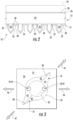
- Fig. 1 is a micrograph of a portion of a membrane-draped microneedle assembly that may be used as part of a drug delivery apparatus, in accordance with a first embodiment of this disclosure.
- Fig. 2 at least some of the underlying shape of the microneedle assembly or array 12 is seen in Fig. 1 , although the actual surface of the microneedle array is substantially hidden from view behind the nontransparent draped membrane 14 in Fig. 1 .
- the draped membrane 14 may be more transparent.
- Fig. 1 further shows pleats (e.g., see pleats 16 in Figs. 3 , 9 and 10A ) and apertures (e.g., see elongate apertures 18 in Figs. 3 and 10A ) in the draped membrane 14, as will be discussed in greater detail below.
- pleats e.g., see pleats 16 in Figs. 3 , 9 and 10A
- apertures e.g., see elongate apertures 18 in
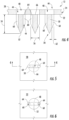
- Fig. 2 schematically illustrates a cross-section of at least a portion of a drug delivery apparatus 10 of the first embodiment, wherein the drug delivery apparatus includes the membrane-draped microneedle assembly of Fig 1 . That is, the apparatus 10 includes a microneedle array or assembly 12, and at least one membrane 14 draped at least partially across microneedles 20 and a front surface 22 (e.g., base surface) of the microneedle assembly.
- the front surface 22 may be referred to as a base or front surface of an assembly base 24 of the microneedle assembly 12.
- the microneedles 20 may extend from the front surface 22 of the assembly base 24.
- the apparatus 10 may further include at least one rate control membrane 26 or other suitable membrane(s) that extend across a back surface 28 of the assembly base 24.
- the back surface 28 and/or the rate control membrane 26 may partially define a reservoir or plenum chamber 29 for providing a fluid to the microneedle assembly 12, wherein the fluid is typically provided to the microneedle assembly 12 by way of the rate control membrane 26 and/or other suitable membrane(s).
- the apparatus 10 may further include other suitable features.
- the fluid supplied from the plenum chamber 29 may be in the form of a liquid drug formulation.
- the membrane-draped microneedles 20 are for penetrating a user's (e.g., patient's) skin, such as for providing the liquid drug formulation into the user's skin, such as by way of the elongate apertures 18 ( Figs. 3 and 10A ).
- the positioning of the elongate apertures 18 and the pleats 16 Figs.
- the size of the pleats 16 may be chosen to at least partially control the size of the elongate apertures and, thus, the surface area of contact between the drug formulation and the skin, as will be discussed in greater detail below.
- Fig. 2 is schematic because, for example, the thicknesses of the draped and rate control membranes 14, 26 are exaggerated.
- the draped membrane 14 may comprise or be a polymeric (e.g., plastic) film, or the like, that may have been formed (e.g., extruded) separately from the microneedle assembly 12, and thereafter mounted to the microneedle assembly, as discussed in greater detail below.
- the draped membrane may comprise or be an embossed or nano-imprinted, polymeric (e.g., plastic) film, or the like.
- the draped membrane 14 may include nanotopography as disclosed by at least one of the documents previously incorporated herein by reference, although such features may be omitted.
- the draped membrane 14 may comprise a polyether ether ketone (PEEK) film that is about five microns thick, or the draped membrane may be any other suitable material, such as a polypropylene film.
- PEEK polyether ether ketone
- the rate control membrane 26 may be fabricated from permeable, semi-permeable or microporous materials known in the art for controlling the rate of flow of drug formulations, or the like. At least in theory, there may be embodiments in which the rate control membrane is omitted. As another example, the rate control membrane 26 may be in combination with and/or replaced by one or more other suitable membranes.
- the microneedles 20 may be described as extending in an outward direction from the front surface 22 of the assembly base 24. This outward direction from the assembly base 24, or the like, may serve as a frame of reference that may be used in the detailed description section of this disclosure for ease of understanding.
- the draped membrane 14 may be characterized as including opposite inner and outer portions 30, 32, and intermediate portions 34 extending between respective inner and outer portions of the draped membrane.
- the present invention may also be described and understood with reference to other suitable frames of reference, such that the present invention is not limited to the frames of reference used in this detailed description section of this disclosure.
- each of the inner portions 30 of the draped membrane may be proximate, facing toward or in opposing face-to-face relation with at least a portion of the front surface 22 of the assembly base 24. More specifically, each of, a majority of, or at least some of the inner portions 30 of the draped membrane 14 may optionally be in opposing face-to-face contact with at least a portion of the front surface 22 of the assembly base 24. Even more specifically, any face-to-face contact between an inner portion 30 and the front surface 22 may optionally extend substantially continuously around an adjacent microneedle 20, such as to define a substantially continuous annular contact area.
- each, a majority of, or at least some of the outer portions 32 of the draped membrane 14 may be proximate or in opposing face-to-face contact with at least an outer portion of a respective microneedle 20. More specifically, each outer portion 32 may be in opposing face-to-face contact with an outer portion of the respective microneedle 20 substantially throughout a substantially continuous annular contact area. Wherever the draped membrane 14 is in opposing face-to-face contact with the microneedle assembly 12, the draped membrane may be adhered to the microneedle assembly, as will be discussed in greater detail below.
- Each of, a majority of, or at least some of the intermediate portions 34 of the draped membrane 14 may be out of contact with and in opposing face-to-face relation with both an inner portion of a respective microneedle 20 and a portion of the front surface 22 of the assembly base 24, so that a gap 36 is defined between the intermediate portion 34 and the microneedle assembly 12.
- the associated gap 36 may extend at least partially along the microneedle; and the gap may also extend at least partially around at least a portion of the microneedle, or the gap may extend substantially completely around at least an inner portion of the microneedle.
- the gaps 36 it is typical for the gaps 36 to be annular and extend completely around the microneedles 20.
- the gaps 36 may taper along a length of the microneedles 20 so that the gaps becomes narrower toward the outer ends of the microneedles.
- the positioning of the elongate apertures 18 and the gaps 36 relative to one another, the size of the gaps, and/or the shape of the gaps may be chosen to at least partially control the size of the elongate apertures and, thus, the surface area of contact between the drug formulation and the skin, as will be discussed in greater detail below.
- the pleats 16 are included and/or controlled for adjusting the size and shape of the gaps 36, although the size and shape of the gaps 36 may also be adjusted in any other suitable manner.
- the draped membrane 14 includes folds that are referred to as pleats 16. More specifically and referring to Fig. 3 , the intermediate portions 34 of the draped membrane 14 may each include pairs of folds that may be referred to as a pair of pleats 16. When the pleats 16 are present, there may be at least a pair of pleats 16 positioned in substantially close proximity to (e.g., substantially engaging and extending outwardly from) at least some of, a majority of, or each of the microneedles 20.
- each pleat may be characterized as including at least one fold line 40 and opposite portions 42 of the draped membrane 14 that are joined to one another along the fold line.
- Each fold line 40 may extend arcuately along at least a portion of the length of the associated microneedle 20.
- each of the opposite portions 42 of the draped membrane 14 that are part of the pleat 16 and are joined together by the fold line 40 of the pleat may be referred to as a pleat part 42.
- the pleat parts 42 of the pleat may be in opposing face-to-face relation with one another.
- the fold line 40 of the pleat may be referred to as defining or being part of a soft, rounded fold such that there may not be any substantially opposing face-to-face contact between the pleat parts 42 of the pleat.
- the pleat parts 42 of the pleat may extend divergently with respect to one another in a direction away from the fold line 40 of the pleat.
- each microneedle 20 of the first embodiment at least partially defines two pathways 44 ( Figs.
- each elongate aperture 18 in the draped membrane 14 is substantially coextensive with, and substantially coaxial with, a portion of the respective pathway 44. That is, the pathways 44 and the elongate apertures 18 are cooperative for delivering the drug formulation from the plenum chamber 29 ( Fig. 2 ) into and/or through the user's skin.
- the pathways 44 of the microneedle 20 and the elongate apertures 18 of the draped membrane 14 are substantially aligned with one another in a pathway-alignment direction 46.
- the pleats 16 and their fold lines 40 are substantially aligned with one another in the pleat-alignment direction 47.
- substantially all of the pathways 44 and the elongate apertures 18 are substantially aligned with one another in the pathway-alignment direction 46
- substantially all of the pleats 16 and their fold lines 40 are substantially aligned with one another in the pleat-alignment direction 47
- the pathway-alignment direction 46 and the pleat-alignment direction 47 are not parallel with one another. More specifically and as shown in Fig. 3 , the pathway-alignment direction 46 and the pleat-alignment direction 47 extend obliquely to one another, as will be discussed in greater detail below.
- a microneedle 20 may have less than or more than two pathways 44 associated therewith, and it is not required that all of the pathways 44 and the elongate apertures 18 be aligned with one another in the pathway-alignment direction 46.
- the pleats 16 may be referred to as major pleats 16, and the draped membrane 14 may further include other pleats, such as minor pleats (e.g., see Fig. 15 ) that may be relatively small as compared to the major pleats 16.
- the pleat-alignment direction of the minor pleats may extend crosswise to the pleat-alignment direction 47 of the major pleats. Accordingly, it may be generally stated that at least some of the pleats (e.g., at least some of the major pleats 16) of the draped membrane 14 may be aligned with one another in the pleat-alignment direction 47. Similarly, at least some of the pathways 44 and elongate apertures 18 may be aligned with one another in the pathway-alignment direction 46.
- the microneedle assembly 12 is configured for delivering a fluidic drug formulation into and/or through the user's skin, such as by being configured to include one or more microneedles 20 extending outwardly from a suitable substrate or support, wherein this substrate or support may be in the form of a support plate, and it may be more generally referred to as the assembly base 24.
- the assembly base 24 has opposite front and back surfaces 22, 28, and the multiple microneedles 20 extend outwardly from the front surface 22.
- the assembly base 24 and microneedles 20 may generally be constructed from a rigid, semi-rigid or flexible sheet of material, such as a metal material, a ceramic material, a polymer (e.g., plastic) material and/or any other suitable material.
- the assembly base 24 and microneedles 20 may be formed from silicon by way of reactive-ion etching, or in any other suitable manner.
- the assembly base 24 typically defines one or more holes 48 extending between, and open at each of, the front and back surfaces 22, 28 for permitting the drug formulation to flow therebetween.
- a single hole 48 may be defined in the assembly base 24 at the location of each microneedle 20 to permit the drug formulation to be delivered from the back surface 28 to such microneedle 20.
- the assembly base 24 may define any other suitable number of holes 48 positioned at and/or spaced apart from the location of each microneedle 20.
- Each microneedle 20 may include a needle base 50 that extends outwardly from the front surface 22 (e.g., base surface) and transitions to a piercing or needle-like shape (e.g., a conical or pyramidal shape, or a cylindrical shape transitioning to a conical or pyramidal shape) having a tip 52 that is distant from the front surface 22.
- the tip 52 of each microneedle 20 is disposed furthest away from the assembly base 24 and may define the smallest dimension (e.g., diameter or cross-sectional width) of each microneedle 20.
- each microneedle 20 may generally define any suitable overall length 54 from the front surface 22 to its tip 52 that is sufficient to allow the microneedles 20 to penetrate the stratum corneum and pass into the epidermis of a user. It may be desirable to limit the overall length 54 of the microneedles 20 such that they do not penetrate through the inner surface of the epidermis and into the dermis, which may advantageously help minimize pain for the patient receiving the drug formulation.
- each microneedle 20 may have an overall length 54 of less than about 1000 micrometers (um), such as less than about 800 um, or less than about 750 um, or less than about 500 um (e.g., an overall length 54 ranging from about 200 um to about 400 um), or any other subranges therebetween.
- the overall length 54 of the microneedles 20 may vary depending on the location at which the apparatus 10 is being used on a user.
- the overall length 54 of the microneedles 20 for an apparatus to be used on a user's leg may differ substantially from the overall length 54 of the microneedles 20 for an apparatus to be used on a user's arm.
- Each microneedle 20 may generally define any suitable aspect ratio (i.e., the overall length 54 over a cross-sectional width dimension 56 of each microneedle 20).
- the aspect ratio may be greater than 2, such as greater than 3 or greater than 4.
- the cross-sectional width dimension 56 e.g., diameter
- the aspect ratio may be determined based on the average cross-sectional width dimension 56.
- Each microneedle 20 may define one or more channels 60 in fluid communication with the holes 48 defined in the assembly base 24.
- the channels 60 may be defined at any suitable location on and/or within each microneedle 20.
- the channels 60 may be defined along an exterior surface of each microneedle 20.
- each channel 60 may be an outwardly open flute defined by the exterior surface of, and extending along the overall length 54 of, a microneedle 20.
- the channels 60 may generally be configured to at least partially form the pathway 44 that enables the drug formulation to flow from the back surface 28 of the assembly base 24, through the holes 48 and into the channels, at which point the drug formulation may be delivered into and/or through the user's skin by way of the apertures 18 ( Figs. 3 and 10A ).
- the channels 60 may be configured to define any suitable cross-sectional shape.
- each channel 60 may define a semi-circular shape.
- each channel 60 may define a non-circular shape, such as a "v" shape or any other suitable cross-sectional shape.
- the dimensions of the channels 60 defined by the microneedles 20 may be specifically selected to induce a capillary flow of the drug formulation.
- capillary flow occurs when the adhesive forces of a fluid to the walls of a channel 60 are greater than the cohesive forces between the liquid molecules.
- the capillary pressure within a channel 60 is inversely proportional to the cross-sectional dimension of the channel and directly proportional to the surface energy of the subject fluid, multiplied by the cosine of the contact angle of the fluid at the interface defined between the fluid and the channel.
- the cross-sectional width dimension 62 of the channel(s) may be selectively controlled, with smaller dimensions generally resulting in higher capillary pressures.
- the cross-sectional width dimension 62 of the channels 60 may be selected so that the cross-sectional area of each channel 60 ranges from about 1,000 square microns (um 2 ) to about 125,000 um 2 , such as from about 1,250 um 2 to about 60,000 um 2 , or from about 6,000 um 2 to about 20,000 um 2 , or any other subranges therebetween.
- the microneedle assembly 12 may generally include any suitable number of microneedles 20.
- the actual number of microneedles 20 included within the microneedle assembly 12 may range from about 10 microneedles per square centimeter (cm 2 ) to about 1,500 microneedles per cm 2 , such as from about 50 microneedles per cm 2 to about 1250 microneedles per cm 2 , or from about 100 microneedles per cm 2 to about 500 microneedles per cm 2 , or any other subranges therebetween.
- the microneedles 20 may generally be arranged on the assembly base 24 in a variety of different patterns, and such patterns may be designed for any particular use.
- the microneedles 20 may be spaced apart in a uniform manner, such as in a rectangular or square grid or in concentric circles.
- the spacing of the microneedles 20 may generally depend on numerous factors, including, but not limited to, the overall length 54 and width of the microneedles 20, as well as the amount and type of drug formulation that is intended to be delivered through the microneedles 20.
- each channel 60 is in fluid communication with its associated hole 48 by way of an opening therebetween, wherein these openings may be referred to as junction openings 64.
- each hole 48 may be partially defined by an inner surface 66 positioned between a pair of the junction openings 64.
- Fig. 5 is schematic because the periphery of the needle base 50 is hidden from view and schematically illustrated by dashed lines.
- Fig. 6 is schematic because a majority of the hole 48 is hidden from view and schematically illustrated by dashed lines.
- the junction openings 64 may vary in area between pathways 44 on a given microneedle 20, and may vary between microneedles 20 on a given microneedle assembly 12.
- the area of each junction opening 64 may vary widely, and will depend on factors such as, for example, the diameter of the microneedle 20, the viscosity of the drug formulation to be moved through the pathways 44 and the quantity of the drug formulation to be delivered.
- the area of each junction opening 64 may also vary depending upon the desired size of the apertures 18 ( Figs. 3 and 10A ) in the draped membrane 14, as will be discussed in greater detail below.
- the area of each junction opening 64 at (e.g., in the plane of) the front surface 22 may be greater than or equal to about 100 square microns, although smaller areas may also be acceptable.
- the area of the junction opening 64 at (e.g., in the plane of) the front surface 22 may be equal to about 150 square microns or greater.
- the junction opening and channel may be substantially concentric and may have substantially the same diameter, as will be discussed in greater detail below.
- the draping process includes the draped membrane 14 and the microneedle assembly 12 being in an overlying configuration or overlying relationship with one another. More specifically, the draped membrane 14 is arranged for being draped over the front surface 22 of the microneedle assembly 12 in Fig. 7 .
- the back surface 28 of the assembly base 24 may be supported by a vacuum box, downdraft system, or downdraft table 68, and/or in any other suitable manner.
- the draped membrane 14 may be at least partially supported by the tips 52 ( Figs. 2 , 4 and 6 ) of the microneedles 20.
- the draped membrane 14 may also be at least partially supported by tensioning rollers, a tenter frame apparatus, and/or in any other suitable manner.
- the pleat-alignment arrows 47 in Fig. 7 may be characterized as being schematically illustrative of tensioning rollers, a tenter frame, or the like.
- the tensioning rollers, tenter frame, or the like may apply tension to the draped membrane 14 in a direction that is substantially the same as both the pleat-alignment direction 47 in the draped membrane and the direction of greatest elongation in the draped membrane 14. That is, the pleats 16 typically form in the direction of greatest elongation in the draped membrane 14.
- the direction of greatest elongation and the pleat-alignment direction 47 in the draped membrane 14 may be at least partially controlled by way of other factors, such as by the draped membrane being originally manufactured and/or previously processed in a manner that imparts a direction of least tensile strength, wherein the direction of least tensile strength may be substantially parallel to both the direction of greatest elongation and the pleat-alignment direction 47. Since the pleat-alignment direction 47 and the direction of greatest elongation in the draped membrane 14 may be substantially parallel to one another, the direction of greatest elongation may also be referred to by the numeral 47.
- the side of the draped membrane 14 that is opposite the microneedle assembly 12 may have pressure and/or heat applied thereto by way of a suitably equipped hood 72 or any other appropriate apparatus. Alternatively or in addition, heat may be applied more directly to the microneedle assembly 12.
- the magnitude and duration of the application of the vacuum, pressure and heating my be controlled to provide the above-discussed face-to-face contacts and so that portions of the draped membrane 14 are drawn at least partially into the open side channels 60 ( Figs. 4 and 6 ) at the outer portions of the microneedles 20. More specifically, the magnitude and duration of the application of the vacuum, pressure and heating my be controlled, and any angle (e.g., angle 76 in Fig.
- the pathway-alignment direction 46 ( Figs. 3 and 8 ) and the direction of greatest elongation 47 ( Figs. 3 and 8 ) may be controlled, so as to: provide the above-discussed contacts between the inner and outer portions 30, 32 of the draped membrane 14 and the respective portions of the microneedle assembly 12; provide and control the configuration of any gaps 36; and provide and control the configuration of any pleats 16. More generally, the operation of one or more of the tensioning rollers, tenter frame, or the like; downdraft table 68; and equipped hood 72 may be controlled for adjusting the size, shape and any orientation of the gaps 36 ( Fig. 2 ), such as by causing the draped membrane 14 to include the pleats 16.
- the draped membrane 14 is typically fixedly mounted to the microneedle assembly 12 due to the resulting substantial conformity in shape between (e.g., the intimate contact between) the draped membrane and the microneedle assembly 12, and typically also as a result of the draped membrane becoming adhered to the microneedle assembly due to heating of the draped membrane. Any heating may be controlled (e.g., limited) so that it does not destroy any nanotopography on the surface of the draped membrane 14 that faces away from the microneedle assembly 12.
- Fig. 8 is a schematic top plan view of the draped membrane 14 and microneedle assembly 12 as they may be arranged in Fig. 7 .
- the microneedle assembly 12 is hidden from view beneath the draped membrane 14 and, therefore, the microneedle assembly is schematically illustrated by dashed lines.
- the pathway-alignment direction 46 and the direction of greatest elongation 47 are not parallel with one another, and more specifically they extend obliquely to one another.
- the angle 76 defined between the pathway-alignment direction 46 and the direction of greatest elongation 47 is substantially the same as the corresponding angle defined between the pathway-alignment direction 46 and the pleat alignment direction 47 in Fig. 3 .
- the angle designated by the numeral 76 is the smaller of the two angles defined between the pathway-alignment direction 46 and the direction of greatest elongation 47.
- the angle 76 may be from about 20 degrees to about 80 degrees, or from about 30 degrees to about 70 degrees, or from about 40 degrees to about 60 degrees, or any other subranges therebetween. More specifically, the angle 76 is shown as being about 50 degrees in Fig. 8 .
- the angle 76 may be from about 10 degrees to about 170 degrees, or from about 20 degrees to about 160 degrees, or from about 30 degrees to about 150 degrees, or from about 40 degrees to about 140 degrees, or from about 50 degrees to about 130 degrees, or from about 60 degrees to about 120 degrees, or from about 70 degrees to about 110 degrees, or from about 80 degrees to about 100 degrees, or about 90 degrees, or any other subranges therebetween.
- the following heights are substantially equal to one another and together vary around the perimeter of each microneedle 22 as a function of the angular position relative to the pleat-alignment direction 47 (e.g., relative to a vertical plane substantially containing the fold lines 40 of a pair of pleats): the height of the gap 36; the height of the upper edge of the draped membrane's intermediate portion 34, which is out of contact with the microneedle 20; and the height of the lower edge of the draped membrane's outer portion 32, which is in contact with the microneedle 20.
- the contact height varies gradually from a maximum contact height (e.g., maximum height MA) in a vertical plane intersecting the pleat-alignment direction 47, to a minimum contact height in a vertical plane that is perpendicular to the vertical plane intersecting the pleat-alignment direction 47.
- the minimum contact height may be less than about 75% of, less than about 50% of, less than about 30% of, or any other suitable percentage of, the maximum contact height.
- the size of the elongate apertures 18 ( Figs. 3 and 10A ) may vary as a function of the contact height, as will be discussed in greater detail below.
- the elongate apertures 18 may be formed by piercing the draped membrane 14 with one or more piercing members after the draped membrane 14 has been mounted to the microneedle array 12.
- the elongate apertures 18 are substantially directly aligned with the channels 60 ( Figs. 4 and 6 ) on the sides of the microneedles 20.
- a portion of the circumference of the elongate aperture 18 shown in Fig. 10A is schematically illustrated by a dashed line.
- the circumference of the elongate aperture 18 extends around an open area defined by the elongate aperture. This open area is for providing the area of contact between the drug formulation and the user's skin.
- Fig. 10B For each of, a majority of, or at least some of the microneedles 20 and their associated elongate apertures 18 of the first embodiment, the relationship therebetween may be as shown in Fig. 10B and discussed in the following.
- Fig. 10B an elongate aperture 18 of the draped membrane 14 is schematically illustrated by dashed lines as being superposed on a channel 60 of a microneedle 20 of the microneedle assembly 12 ( Fig. 4 ).
- the elongate aperture 18 has a length L1 and width W1
- the microneedle 20 has an overall length L2 corresponding to the overall length 54 shown in Fig.
- the channel 60 has a width W2, and an elevational distance D, or the like, is defined between an apex of the tip 52 of the microneedle 20 and the end of the elongate aperture 18 that is closest to the tip 52.
- the lengths L1, L2 and distance D extend in the same direction as one another, or more generally they extend in substantially the same direction as one another.
- the widths W1, W2 extend in the same direction as one another, or more generally they extend in substantially in the same direction as one another.
- the length L1 of the aperture 18 is greater than the width W1 of the aperture 18, so that the aperture 18 is elongate or elongated.
- the length L1 of the elongate aperture 18 may be at least about twice as large as the width W1 of the elongate aperture, or the length L1 of the elongate aperture may be at least about three, for or five times as large as the width W1 of the elongate aperture.
- the apparatus 10 may be configured such that the lengths L1 of the apertures 18 are smaller, for example so that the lengths L1 of the apertures may be about the same size as, or any other suitable ratio as compared to, the widths W1 of the apertures.
- the major axis of the elongate aperture 18 is parallel, or substantially parallel, to the major axis of the channel 60.
- the length L1 of the elongate aperture 18 may be within a range of at least 10% to no more than 80% of the overall length L2 of the microneedle 20, or any subranges therebetween. More generally, the length L1 of the elongate aperture 18 may be within a range of from about 10% to about 80% of the overall length L2 of the microneedle 20, or any subranges therebetween.
- the length L1 of the elongate aperture 18 may be within a range of at least 20% to no more than 50% of the overall length L2 of the microneedle 20, the length L1 of the elongate aperture 18 may be within a range of from about 20% to about 50% of the overall length L2 of the microneedle 20, or any other subranges therebetween. Even more specifically, the length L1 of the elongate aperture 18 may about 30% of the overall length L2 of the microneedle 20.
- the minor axis of the elongate aperture 18 may be perpendicular to, or substantially perpendicular to, the major axis of the channel 60.
- the width W1 of the elongate aperture 18 may be within a range of at least 70% to no more than 130% of the width W2 of the channel 60, or any subranges therebetween. More generally, the width W1 of the elongate aperture 18 may be within a range of about 70% to about 130% of the width W2 of the channel 60, or any subranges therebetween.
- the width W1 of the elongate aperture 18 may be within a range of at least 90% to no more than 110% of the width W2 of the channel 60, the width W1 of the elongate aperture 18 may be within a range of about 90% to about 110% of the width W2 of the channel 60, or any other subranges therebetween.
- the elevational distance D between the apex of the tip 52 of the microneedle 20 and the end of the elongate aperture 18 that is closest to the tip 52 may be no more than 30% of the overall length L2 of the microneedle 20, or any subranges therein. More generally, the elevational distance D between the apex of the tip 52 of the microneedle 20 and the end of the elongate aperture 18 that is closest to the tip 52 may be less than about 30% of the overall length L2 of the microneedle 20, or any subranges therein.
- the elevational distance D between the apex of the tip 52 of the microneedle 20 and the end of the elongate aperture 18 that is closest to the tip 52 may be no more than 10% of the overall length L2 of the microneedle 20, or any subranges therein.
- the elevational distance D between the apex of the tip 52 of the microneedle 20 and the end of the elongate aperture 18 that is closest to the tip 52 may less than about 10% of the overall length L2 of the microneedle 20, or any subranges therein.
- the length L1 of the elongate aperture 18 may be about 40% of the overall length L2 of the microneedle 20, the elevational distance D between the apex of the tip 52 of the microneedle 20 and the end of the elongate aperture 18 that is closest to the tip 52 may be about equal to the length L3 of the conical, or substantially conical, tip 52 of the microneedle 20, or any subranges therebetween.
- the length L3 of the tip 52 may be about 20% of the overall length L2 of the microneedle 20. More specifically, the length L3 of the tip 52 may be about 60um. More generally, the length L3 of the tip 52 may be within a range of about 10% to about 30% of the overall length L2 of the microneedle 20, or any subranges therebetween.
- the piercing members that form the elongate apertures 18 may be in the form of laser beams or laser beam portions 82.
- the portion of the circumference of the elongate aperture 18 that is hidden from view behind the forwardmost laser beam portion 82 is schematically illustrated by a dashed line.
- the laser beam portions 82 may be portions of, or otherwise derived from, a relatively wide precursor laser beam 84 originating from a laser generator 86.
- the laser generator 86 may comprise a laser diode or any other suitable device for generating or otherwise providing the precursor beam 84.
- the laser generator 86 and the draped microneedle assembly 12 may be arranged so that the microneedle assembly 12 is positioned between the laser generator and the draped membrane 14, so that the precursor beam 84 is focused or otherwise directed toward and into the hole 48 ( Figs. 4 and 5 ) from the side of the assembly base 24 that is adjacent the back surface 28.
- the inner surface 66 ( Figs. 4 and 5 ) of the assembly base 24 and optionally also the back surface 28 of the assembly base may function as one or more obstructions or a mask for obstructing passage of a portion of the precursor beam 84.
- the obstructing of the passage of the precursor beam 84 may be characterized as splitting the precursor beam and, thus, providing at least the two beam portions 82.
- the beam portions 82 shown in Fig. 10A are cylindrical and the pathways 44 ( Figs. 3 and 4 ) may be configured so that the elongate apertures 18 are formed in the draped membrane 14 substantially precisely at the location of the channels 60 ( Figs. 4 and 6 ).
- any portions of the draped membrane 14 that are positioned in the channels 60 are typically exposed to the beam portions 82 and are, thus, removed (e.g., vaporized).
- any portions of the draped membrane 14 that are positioned in the path of the beam portions 82 are typically removed, and the collimated beam portions shown in Fig. 10A are coaxial with, and have the same peripheral shape as, the junction openings 64 ( Figs. 5 and 6 ).
- the configuration of the junction openings 64 may vary, and for at least this reason the configurations of the beam portions 82 may vary such that the configurations of the apertures 18 may vary.
- the beams 82, 84 may be also varied in other ways, such as independently of the junction openings 64.
- the precursor beam 84 may simultaneously be directed into multiple holes 48 ( Figs. 4-6 ) and may be simultaneously split into a multiplicity of beam portions 82.
- the laser generator 86 may be mounted to the movable carriage of a computer-controlled gantry system, or the like, wherein the arrows 88 schematically illustrate the laser generator being moved by the gantry system or another suitable device.
- Second through fourth embodiments of this disclosure are like the first embodiment, except for variations noted and variations that will be apparent to those of ordinary skill in the art.
- the first and second embodiments are identical except for differences in the angle 76 ( Fig. 8 ) and differences caused by the differences in the angle 76.
- the pathway-alignment and pleat-alignment directions 46, 47 and the direction of greatest elongation 47 all extend substantially in the same direction, so that the elongate apertures 18 of the second embodiment are shorter than the elongate apertures 18 of the first embodiment. More generally, the size of a gap 36 ( Fig.
- the size of an associated aperture 18 in the draped membrane 14 can be inversely proportional to one another.
- the length of the (e.g., laser-formed) elongate apertures 18 may be more dependent upon the size (e.g., height) of the pleats 16, because the pleats may reduce the amount of the draped membrane 14 that extends into the channels 60.
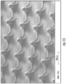
- the height of the pleats 16 is schematically illustrated by the imaginary dimension line 80 in Figs. 12 and 13 .
- the junction openings 64 may be configured so that only the portions of the draped membrane 14 that are positioned in the channels 60 are perforated (e.g., by the laser) to form the elongate apertures 18.
- the elongate apertures 18 may extend both above and below the height of the pleats 16 (e.g., dimension line 80 in Figs. 9 and 10A ).
- the elongate apertures 18 may only extend above the height of the pleats 16 (e.g., dimension line 80 in Figs. 12 and 13 ). Accordingly, when the pleat folds 40 do not align with the needle channels 60, the lengths of the (e.g., laser-formed) elongate apertures 18 are less dependent upon the height of the pleats 16.
- the third embodiment may be like the variation to the first embodiment, except that the draping process of the third embodiment does not include the draped membrane 14 being drawn or otherwise forced into the channels 60.
- the apertures 18 in the draped membrane 14 of Fig. 14 are formed only at the ends of the channels 60, so that the apertures may not be elongate and are only located in close proximity to the tips 52.
- each channel 60 may be open to multiple apertures 18 in the draped membrane 14. That is, there may be separate apertures 18 respectively located at the top and proximate the bottom of each channel 60.
- the pleats 16 may include both relatively large pleats (e.g., major pleats) and relatively small pleats (e.g., minor pleats) extending crosswise to the relatively large pleats, and the relatively large pleats may optionally extend all the way between adjacent microneedles 20.
- a draped microneedle array 12 may be configured and used in a manner that seeks to provide good delivery of the drug formulation through the user's skin by way of the microneedles 20 penetrating the outer barrier layers of the skin and causing the elongate apertures 18 and any optional nanotopography of the draped membrane 14 to come into good contact with living skin cells, so that the elongate apertures 18 provide good surface areas of contact between the drug formulation and the living skin cells, and any nanotopography of the draped membrane 14 (e.g., a nano-imprinted film) may enhance the permeability of the skin.
- any nanotopography of the draped membrane 14 e.g., a nano-imprinted film
- the draped microneedle array 12 may simultaneously provide good contact between the skin and the film 14 while still providing good total surface area contact between the drug formulation fluid and the skin by way of the elongate apertures 18, wherein these results may be achieved, for example, by controlling the configurations of the gaps 36 (e.g., such as by controlling any pleated shape of the draped nano-imprinted film 14) and/or the laser perforating process, as discussed above.
- positional frames of reference such as “top,” “bottom,” “front,” “back,” “over,” “above,” “below,” and “height” have been used.
- the present invention is not limited to the positional frames of reference used in the detailed description section of this disclosure because, for example, the apparatus 10 of the exemplary embodiment may be configured so that it may be used in both inverted and uninverted configurations.
- each microneedle 20 may have been described as having at least a pair of pleats 16 associated therewith; however, it is within the scope of the exemplary embodiments for the draped membrane 14 not to include pleats in close proximity to each and every one of the microneedles 20.
- references may have been made in the forgoing to each of one or more of other features; however, it is within the scope of the exemplary embodiments for there to be variations between one or more features of a plurality of features.
Landscapes
- Health & Medical Sciences (AREA)
- Engineering & Computer Science (AREA)
- Dermatology (AREA)
- Medical Informatics (AREA)
- Anesthesiology (AREA)
- Biomedical Technology (AREA)
- Heart & Thoracic Surgery (AREA)
- Hematology (AREA)
- Life Sciences & Earth Sciences (AREA)
- Animal Behavior & Ethology (AREA)
- General Health & Medical Sciences (AREA)
- Public Health (AREA)
- Veterinary Medicine (AREA)
- Physics & Mathematics (AREA)
- Electromagnetism (AREA)
- Toxicology (AREA)
- Oral & Maxillofacial Surgery (AREA)
- Thermal Sciences (AREA)
- Media Introduction/Drainage Providing Device (AREA)
- Surgical Instruments (AREA)
Claims (11)
- Einrichtung (10), umfassend:eine Mikronadelanordnung (12), umfassendeine Grundfläche (22),eine Vielzahl von Mikronadeln (20), die sich von der Grundfläche (22) nach außen erstrecken, undeinen mindestens teilweise durch eine Mikronadel (20) der Mikronadelanordnung (12) definierten Pfad (44); undeine Membran (14), die über mindestens einen Teil der Vielzahl von Mikronadeln (20) gelegt ist, die Membran (14) umfassend:eine längliche Durchbrechung (18), die entlang einer Länge des Pfades (44) offen ist, sodass die längliche Durchbrechung (18) in Fluidverbindung mit dem Pfad (44) ist, wobei die längliche Durchbrechung (18) eine Länge (L1) und eine Breite (W1) aufweist, wobei die Länge (L1) größer als die Breite (W1) ist,einen äußeren Teil (32) in gegenüberliegendem Flächenkontakt mit mindestens einem äußeren Teil der Mikronadel (20), undeinem inneren Teil (30), der mindestens einem Teil der Grundfläche (22) zugewandt ist, wobeimindestens ein Teil der Membran (14) von der Mikronadel (20) beabstandet ist, sodass ein Zwischenraum (36) zwischen der Membran (14) und der Mikronadel (20) definiert ist;sich der Zwischenraum (36) sowohl mindestens teilweise um die Mikronadel (20) herum als auch mindestens teilweise entlang der Mikronadel (20) erstreckt;die Membran (14) eine Falte (16) definiert, die sich zwischen dem inneren und dem äußeren Teil (30, 32) der Membran (14) erstreckt; unddie Falte (16) relativ zu der länglichen Durchbrechung (18) positioniert ist, um die Größe der länglichen Durchbrechung (18) und die Größe und Form des Zwischenraums (36) zu regeln.
- Einrichtung nach Anspruch 1, wobei die Länge (L1) der länglichen Durchbrechung (18) mindestens etwa doppelt so groß ist wie eine Breite (W1) der länglichen Durchbrechung (18).
- Einrichtung nach Anspruch 1, wobei sich die Länge (L1) der länglichen Durchbrechung (18) in eine Richtung erstreckt und sich eine Länge des Pfades (44) in eine Richtung erstreckt, die im Wesentlichen dieselbe Richtung ist, in die sich die Länge (L1) der länglichen Durchbrechung (18) erstreckt.
- Einrichtung nach Anspruch 1, wobei:der Pfad (44) einen Kanal (60) umfasst, der mindestens teilweise von der Mikronadel (20) definiert ist;sich eine Länge des Kanals (60) in eine Richtung erstreckt; undsich eine Länge (L1) der länglichen Durchbrechung (18) in eine Richtung erstreckt, die im Wesentlichen dieselbe Richtung ist, in die sich die Länge des Kanals (60) erstreckt.
- Einrichtung nach Anspruch 4, wobei eine Breite (W1) der länglichen Durchbrechung (18) innerhalb eines Bereichs von etwa 70 % bis etwa 130 % einer Breite des Kanals (60) liegt.
- Einrichtung nach Anspruch 1, wobei:die Grundfläche (22) eine erste Fläche einer Grundstruktur der Mikronadelanordnung (12) ist;die Grundstruktur ferner eine zweite Fläche (28) umfasst, die der ersten Fläche gegenüberliegt; unddie Einrichtung (10) ferner einen Behälter (29) umfasst, der zu der zweiten Fläche (28) benachbart und in Fluidverbindung mit der Mikronadel (20) ist, wobei der Behälter (29) über den Pfad (44) in Fluidverbindung mit der länglichen Durchbrechung (18) der Membran (14) ist.
- Einrichtung nach Anspruch 1, wobei eine Länge (L1) der länglichen Durchbrechung (18) innerhalb eines Bereichs von etwa 10 % bis etwa 80 % einer Gesamtlänge (L2) der Mikronadel (20) liegt.
- Einrichtung nach Anspruch 1, wobei:die längliche Durchbrechung (18) gegenüberliegende erste und zweite Enden beinhaltet;das erste Ende zwischen dem zweiten Ende und einem Scheitelpunkt einer Spitze (52) der Mikronadel (20) positioniert ist; undein Abstand zwischen dem ersten Ende und dem Scheitelpunkt der Spitze (52) geringer ist als etwa 30 % einer Gesamtlänge (L2) der Mikronadel (20).
- Einrichtung nach Anspruch 1, wobei:die Falte (16) benachbart zu der Mikronadel (20) positioniert ist; undeine Faltlinie (40) der Falte (16) nicht fluchtend ist mit mindestens einem Merkmal, das ausgewählt ist aus der Gruppe bestehend aus dem Pfad (44) und der länglichen Durchbrechung (18).
- Einrichtung nach Anspruch 1, wobei:die längliche Durchbrechung (18) gegenüberliegende erste und zweite Enden beinhaltet;das erste Ende zwischen dem zweiten Ende und einem Scheitelpunkt einer Spitze (52) der Mikronadel (20) positioniert ist; undein Abstand zwischen dem ersten Ende und dem Scheitelpunkt (52) etwa gleich einer Länge der Spitze (L3) der Mikronadel (20) ist.
- Einrichtung nach Anspruch 10, wobei die Länge der Spitze (L3) der Mikronadel (20) innerhalb eines Bereichs von etwa 10 % bis etwa 30 % einer Gesamtlänge (L2) der Mikronadel (20) liegt.
Applications Claiming Priority (3)
| Application Number | Priority Date | Filing Date | Title |
|---|---|---|---|
| US201461996148P | 2014-04-30 | 2014-04-30 | |
| EP15785673.3A EP3137152B1 (de) | 2014-04-30 | 2015-04-29 | Drapierte mikronadelanordnung |
| PCT/US2015/028154 WO2015168214A1 (en) | 2014-04-30 | 2015-04-29 | Draped microneedle array |
Related Parent Applications (1)
| Application Number | Title | Priority Date | Filing Date |
|---|---|---|---|
| EP15785673.3A Division EP3137152B1 (de) | 2014-04-30 | 2015-04-29 | Drapierte mikronadelanordnung |
Publications (2)
| Publication Number | Publication Date |
|---|---|
| EP3597261A1 EP3597261A1 (de) | 2020-01-22 |
| EP3597261B1 true EP3597261B1 (de) | 2025-03-12 |
Family
ID=54359268
Family Applications (2)
| Application Number | Title | Priority Date | Filing Date |
|---|---|---|---|
| EP19196358.6A Active EP3597261B1 (de) | 2014-04-30 | 2015-04-29 | Drapierte mikronadelanordnung |
| EP15785673.3A Active EP3137152B1 (de) | 2014-04-30 | 2015-04-29 | Drapierte mikronadelanordnung |
Family Applications After (1)
| Application Number | Title | Priority Date | Filing Date |
|---|---|---|---|
| EP15785673.3A Active EP3137152B1 (de) | 2014-04-30 | 2015-04-29 | Drapierte mikronadelanordnung |
Country Status (10)
| Country | Link |
|---|---|
| US (1) | US9962536B2 (de) |
| EP (2) | EP3597261B1 (de) |
| JP (1) | JP6211212B2 (de) |
| KR (1) | KR101724251B1 (de) |
| CN (1) | CN106163607B (de) |
| AU (1) | AU2015253257B2 (de) |
| CA (1) | CA2945502C (de) |
| MX (2) | MX376005B (de) |
| RU (1) | RU2627150C1 (de) |
| WO (1) | WO2015168214A1 (de) |
Families Citing this family (11)
| Publication number | Priority date | Publication date | Assignee | Title |
|---|---|---|---|---|
| AU2017258749B2 (en) * | 2016-04-29 | 2022-06-16 | Vivasor, Inc. | Microneedle array assembly, drug delivery device and method for administering liquid across a broad area at low pressure |
| JPWO2019111959A1 (ja) * | 2017-12-05 | 2020-12-17 | 古河電気工業株式会社 | 機能性部材及びその製造方法 |
| WO2021113585A1 (en) | 2019-12-05 | 2021-06-10 | Sorrento Therapeutics, Inc. | Method of treating cancer by administration of an anti-pd-1 or anti-pd-l1 therapeutic agent via a lymphatic delivery device |
| FR3108837B1 (fr) * | 2020-04-06 | 2022-03-11 | Pkvitality | Dispositif de mesure d’analyte comprenant un patch adhesif |
| JP2023523952A (ja) | 2020-04-28 | 2023-06-08 | ティコナ・エルエルシー | マイクロニードルアセンブリ |
| CN117813128A (zh) | 2021-01-22 | 2024-04-02 | 索伦托药业有限公司 | 用于微升级淋巴递送冠状病毒疫苗的装置 |
| WO2022192594A2 (en) | 2021-03-11 | 2022-09-15 | Sorrento Therapeutics, Inc. | Nucleic acid molecules and vaccines comprising same for the prevention and treatment of coronavirus infections and disease |
| WO2022261262A1 (en) | 2021-06-09 | 2022-12-15 | Sorrento Therapeutics, Inc. | Method of treating cancer by administration of an anti-pd-1 or anti-pd-l1 therapeutic agent via a lymphatic microneedle delivery device |
| US20250120905A1 (en) | 2021-08-18 | 2025-04-17 | Vivasor, Inc | Therapeutic agents targeting the lymphatic system |
| CN113712547B (zh) * | 2021-09-07 | 2023-12-29 | 集美大学 | 多槽微针阵列及其制备方法、生物检测微针传感器 |
| WO2025129128A1 (en) | 2023-12-15 | 2025-06-19 | Vivasor, Inc. | Compositions and methods for non-viral delivery of therapeutic compounds |
Family Cites Families (22)
| Publication number | Priority date | Publication date | Assignee | Title |
|---|---|---|---|---|
| SU1134199A1 (ru) * | 1981-12-09 | 1985-01-15 | Днепропетровский Ордена Трудового Красного Знамени Медицинский Институт | Устройство дл одноразового введени жидкости в сосуды и забора крови |
| US6503231B1 (en) | 1998-06-10 | 2003-01-07 | Georgia Tech Research Corporation | Microneedle device for transport of molecules across tissue |
| US6558361B1 (en) | 2000-03-09 | 2003-05-06 | Nanopass Ltd. | Systems and methods for the transport of fluids through a biological barrier and production techniques for such systems |
| US6565532B1 (en) * | 2000-07-12 | 2003-05-20 | The Procter & Gamble Company | Microneedle apparatus used for marking skin and for dispensing semi-permanent subcutaneous makeup |
| US7141034B2 (en) * | 2000-06-08 | 2006-11-28 | Altea Therapeutics Corporation | Transdermal drug delivery device, method of making same and method of using same |
| US7108681B2 (en) * | 2000-10-16 | 2006-09-19 | Corium International, Inc. | Microstructures for delivering a composition cutaneously to skin |
| US6767341B2 (en) * | 2001-06-13 | 2004-07-27 | Abbott Laboratories | Microneedles for minimally invasive drug delivery |
| EP1469903A2 (de) | 2001-09-28 | 2004-10-27 | BioValve Technologies, Inc. | Mikronadel mit membran |
| US6908453B2 (en) | 2002-01-15 | 2005-06-21 | 3M Innovative Properties Company | Microneedle devices and methods of manufacture |
| US7578954B2 (en) * | 2003-02-24 | 2009-08-25 | Corium International, Inc. | Method for manufacturing microstructures having multiple microelements with through-holes |
| US20050079711A1 (en) * | 2003-10-10 | 2005-04-14 | Cabot Microelectronics Corp. | Hollow tip array with nanometer size openings and formation thereof |
| WO2005094526A2 (en) * | 2004-03-24 | 2005-10-13 | Corium International, Inc. | Transdermal delivery device |
| WO2006055844A2 (en) * | 2004-11-18 | 2006-05-26 | 3M Innovative Properties Company | Method of contact coating a microneedle array |
| WO2007116959A1 (ja) * | 2006-04-07 | 2007-10-18 | Hisamitsu Pharmaceutical Co., Inc. | マイクロニードルデバイスおよびマイクロニードル付き経皮薬物投与装置 |
| KR100793615B1 (ko) | 2006-07-21 | 2008-01-10 | 연세대학교 산학협력단 | 생분해성 솔리드 마이크로니들 및 이의 제조방법 |
| DE102006040642A1 (de) * | 2006-08-30 | 2008-03-13 | Robert Bosch Gmbh | Mikronadeln zur Platzierung in der Haut zwecks transdermaler Applikation von Pharmazeutika |
| CN101829396B (zh) * | 2009-03-27 | 2013-01-30 | 清华大学 | 微针阵列芯片及利用其的经皮给药贴剂及其制备方法 |
| US20110144591A1 (en) | 2009-12-11 | 2011-06-16 | Ross Russell F | Transdermal Delivery Device |
| RU2570280C2 (ru) | 2010-04-28 | 2015-12-10 | Кимберли-Кларк Ворлдвайд, Инк. | Композитная матрица микроигл, содержащая на поверхности наноструктуры |
| CN101912663B (zh) * | 2010-08-18 | 2013-09-04 | 清华大学 | 空心微针阵列芯片、经皮给药贴片、器件及制备方法 |
| WO2013170171A1 (en) * | 2012-05-11 | 2013-11-14 | 10X Technology Llc | Hollow silica glass microneedle arrays and method and apparatus for manufacturing same |
| KR102219636B1 (ko) * | 2012-12-27 | 2021-02-23 | 쓰리엠 이노베이티브 프로퍼티즈 컴파니 | 중공형 마이크로니들을 갖는 물품 및 제조 방법 |
-
2015
- 2015-04-29 AU AU2015253257A patent/AU2015253257B2/en not_active Ceased
- 2015-04-29 EP EP19196358.6A patent/EP3597261B1/de active Active
- 2015-04-29 RU RU2016143371A patent/RU2627150C1/ru not_active IP Right Cessation
- 2015-04-29 MX MX2016013200A patent/MX376005B/es active IP Right Grant
- 2015-04-29 KR KR1020167030818A patent/KR101724251B1/ko not_active Expired - Fee Related
- 2015-04-29 EP EP15785673.3A patent/EP3137152B1/de active Active
- 2015-04-29 US US14/914,302 patent/US9962536B2/en active Active
- 2015-04-29 JP JP2016562966A patent/JP6211212B2/ja active Active
- 2015-04-29 CN CN201580018765.0A patent/CN106163607B/zh not_active Expired - Fee Related
- 2015-04-29 CA CA2945502A patent/CA2945502C/en active Active
- 2015-04-29 WO PCT/US2015/028154 patent/WO2015168214A1/en not_active Ceased
-
2016
- 2016-10-07 MX MX2020010240A patent/MX2020010240A/es unknown
Also Published As
| Publication number | Publication date |
|---|---|
| JP6211212B2 (ja) | 2017-10-11 |
| US9962536B2 (en) | 2018-05-08 |
| MX2016013200A (es) | 2017-01-16 |
| KR101724251B1 (ko) | 2017-04-06 |
| EP3137152B1 (de) | 2019-09-25 |
| RU2627150C1 (ru) | 2017-08-03 |
| US20170036005A1 (en) | 2017-02-09 |
| JP2017511216A (ja) | 2017-04-20 |
| WO2015168214A1 (en) | 2015-11-05 |
| CA2945502C (en) | 2018-01-02 |
| EP3597261A1 (de) | 2020-01-22 |
| EP3137152A4 (de) | 2018-03-14 |
| MX376005B (es) | 2025-03-07 |
| AU2015253257A1 (en) | 2016-11-17 |
| CN106163607A (zh) | 2016-11-23 |
| AU2015253257B2 (en) | 2019-09-26 |
| EP3137152A1 (de) | 2017-03-08 |
| CA2945502A1 (en) | 2015-11-25 |
| KR20160135366A (ko) | 2016-11-25 |
| CN106163607B (zh) | 2018-03-27 |
| MX2020010240A (es) | 2020-10-16 |
Similar Documents
| Publication | Publication Date | Title |
|---|---|---|
| EP3597261B1 (de) | Drapierte mikronadelanordnung | |
| AU2022202361B2 (en) | Microneedle array assembly, drug delivery device and method for administering liquid across a broad area at low pressure | |
| US9861801B2 (en) | Drug delivery device | |
| US8636696B2 (en) | Transdermal device containing microneedles | |
| EP3831438B1 (de) | Mikronadel-array-anordnung | |
| JP4836392B2 (ja) | 物質を抜き取り又は投与するための皮膚透過性強化装置及びその装置を製造するための方法 | |
| CN102639184B (zh) | 透皮输送装置 | |
| BR112015020328B1 (pt) | Dispositivo de aplicação transdérmica de droga | |
| US20150174386A1 (en) | Transdermal device containing microneedles | |
| JP7230377B2 (ja) | マイクロニードル |
Legal Events
| Date | Code | Title | Description |
|---|---|---|---|
| PUAI | Public reference made under article 153(3) epc to a published international application that has entered the european phase |
Free format text: ORIGINAL CODE: 0009012 |
|
| STAA | Information on the status of an ep patent application or granted ep patent |
Free format text: STATUS: THE APPLICATION HAS BEEN PUBLISHED |
|
| AC | Divisional application: reference to earlier application |
Ref document number: 3137152 Country of ref document: EP Kind code of ref document: P |
|
| AK | Designated contracting states |
Kind code of ref document: A1 Designated state(s): AL AT BE BG CH CY CZ DE DK EE ES FI FR GB GR HR HU IE IS IT LI LT LU LV MC MK MT NL NO PL PT RO RS SE SI SK SM TR |
|
| STAA | Information on the status of an ep patent application or granted ep patent |
Free format text: STATUS: REQUEST FOR EXAMINATION WAS MADE |
|
| 17P | Request for examination filed |
Effective date: 20200715 |
|
| RBV | Designated contracting states (corrected) |
Designated state(s): AL AT BE BG CH CY CZ DE DK EE ES FI FR GB GR HR HU IE IS IT LI LT LU LV MC MK MT NL NO PL PT RO RS SE SI SK SM TR |
|
| GRAP | Despatch of communication of intention to grant a patent |
Free format text: ORIGINAL CODE: EPIDOSNIGR1 |
|
| STAA | Information on the status of an ep patent application or granted ep patent |
Free format text: STATUS: GRANT OF PATENT IS INTENDED |
|
| INTG | Intention to grant announced |
Effective date: 20221020 |
|
| GRAJ | Information related to disapproval of communication of intention to grant by the applicant or resumption of examination proceedings by the epo deleted |
Free format text: ORIGINAL CODE: EPIDOSDIGR1 |
|
| STAA | Information on the status of an ep patent application or granted ep patent |
Free format text: STATUS: REQUEST FOR EXAMINATION WAS MADE |
|
| INTC | Intention to grant announced (deleted) | ||
| GRAP | Despatch of communication of intention to grant a patent |
Free format text: ORIGINAL CODE: EPIDOSNIGR1 |
|
| STAA | Information on the status of an ep patent application or granted ep patent |
Free format text: STATUS: GRANT OF PATENT IS INTENDED |
|
| INTG | Intention to grant announced |
Effective date: 20230412 |
|
| GRAJ | Information related to disapproval of communication of intention to grant by the applicant or resumption of examination proceedings by the epo deleted |
Free format text: ORIGINAL CODE: EPIDOSDIGR1 |
|
| STAA | Information on the status of an ep patent application or granted ep patent |
Free format text: STATUS: REQUEST FOR EXAMINATION WAS MADE |
|
| INTC | Intention to grant announced (deleted) | ||
| GRAP | Despatch of communication of intention to grant a patent |
Free format text: ORIGINAL CODE: EPIDOSNIGR1 |
|
| STAA | Information on the status of an ep patent application or granted ep patent |
Free format text: STATUS: GRANT OF PATENT IS INTENDED |
|
| INTG | Intention to grant announced |
Effective date: 20231026 |
|
| RAP1 | Party data changed (applicant data changed or rights of an application transferred) |
Owner name: VIVASOR, INC. |
|
| GRAS | Grant fee paid |
Free format text: ORIGINAL CODE: EPIDOSNIGR3 |
|
| GRAA | (expected) grant |
Free format text: ORIGINAL CODE: 0009210 |
|
| STAA | Information on the status of an ep patent application or granted ep patent |
Free format text: STATUS: THE PATENT HAS BEEN GRANTED |
|
| AC | Divisional application: reference to earlier application |
Ref document number: 3137152 Country of ref document: EP Kind code of ref document: P |
|
| AK | Designated contracting states |
Kind code of ref document: B1 Designated state(s): AL AT BE BG CH CY CZ DE DK EE ES FI FR GB GR HR HU IE IS IT LI LT LU LV MC MK MT NL NO PL PT RO RS SE SI SK SM TR |
|
| REG | Reference to a national code |
Ref country code: GB Ref legal event code: FG4D |
|
| REG | Reference to a national code |
Ref country code: CH Ref legal event code: EP |
|
| REG | Reference to a national code |
Ref country code: DE Ref legal event code: R096 Ref document number: 602015091219 Country of ref document: DE |
|
| REG | Reference to a national code |
Ref country code: IE Ref legal event code: FG4D |
|
| PG25 | Lapsed in a contracting state [announced via postgrant information from national office to epo] |
Ref country code: RS Free format text: LAPSE BECAUSE OF FAILURE TO SUBMIT A TRANSLATION OF THE DESCRIPTION OR TO PAY THE FEE WITHIN THE PRESCRIBED TIME-LIMIT Effective date: 20250612 |
|
| PG25 | Lapsed in a contracting state [announced via postgrant information from national office to epo] |
Ref country code: FI Free format text: LAPSE BECAUSE OF FAILURE TO SUBMIT A TRANSLATION OF THE DESCRIPTION OR TO PAY THE FEE WITHIN THE PRESCRIBED TIME-LIMIT Effective date: 20250312 |
|
| PG25 | Lapsed in a contracting state [announced via postgrant information from national office to epo] |
Ref country code: ES Free format text: LAPSE BECAUSE OF FAILURE TO SUBMIT A TRANSLATION OF THE DESCRIPTION OR TO PAY THE FEE WITHIN THE PRESCRIBED TIME-LIMIT Effective date: 20250312 |
|
| REG | Reference to a national code |
Ref country code: LT Ref legal event code: MG9D |
|
| PG25 | Lapsed in a contracting state [announced via postgrant information from national office to epo] |
Ref country code: NO Free format text: LAPSE BECAUSE OF FAILURE TO SUBMIT A TRANSLATION OF THE DESCRIPTION OR TO PAY THE FEE WITHIN THE PRESCRIBED TIME-LIMIT Effective date: 20250612 |
|
| PG25 | Lapsed in a contracting state [announced via postgrant information from national office to epo] |
Ref country code: HR Free format text: LAPSE BECAUSE OF FAILURE TO SUBMIT A TRANSLATION OF THE DESCRIPTION OR TO PAY THE FEE WITHIN THE PRESCRIBED TIME-LIMIT Effective date: 20250312 |
|
| REG | Reference to a national code |
Ref country code: NL Ref legal event code: MP Effective date: 20250312 |
|
| PG25 | Lapsed in a contracting state [announced via postgrant information from national office to epo] |
Ref country code: LV Free format text: LAPSE BECAUSE OF FAILURE TO SUBMIT A TRANSLATION OF THE DESCRIPTION OR TO PAY THE FEE WITHIN THE PRESCRIBED TIME-LIMIT Effective date: 20250312 |
|
| PG25 | Lapsed in a contracting state [announced via postgrant information from national office to epo] |
Ref country code: GR Free format text: LAPSE BECAUSE OF FAILURE TO SUBMIT A TRANSLATION OF THE DESCRIPTION OR TO PAY THE FEE WITHIN THE PRESCRIBED TIME-LIMIT Effective date: 20250613 Ref country code: BG Free format text: LAPSE BECAUSE OF FAILURE TO SUBMIT A TRANSLATION OF THE DESCRIPTION OR TO PAY THE FEE WITHIN THE PRESCRIBED TIME-LIMIT Effective date: 20250312 |
|
| REG | Reference to a national code |
Ref country code: AT Ref legal event code: MK05 Ref document number: 1774522 Country of ref document: AT Kind code of ref document: T Effective date: 20250312 |
|
| PG25 | Lapsed in a contracting state [announced via postgrant information from national office to epo] |
Ref country code: NL Free format text: LAPSE BECAUSE OF FAILURE TO SUBMIT A TRANSLATION OF THE DESCRIPTION OR TO PAY THE FEE WITHIN THE PRESCRIBED TIME-LIMIT Effective date: 20250312 |
|
| PG25 | Lapsed in a contracting state [announced via postgrant information from national office to epo] |
Ref country code: SE Free format text: LAPSE BECAUSE OF FAILURE TO SUBMIT A TRANSLATION OF THE DESCRIPTION OR TO PAY THE FEE WITHIN THE PRESCRIBED TIME-LIMIT Effective date: 20250312 |
|
| PG25 | Lapsed in a contracting state [announced via postgrant information from national office to epo] |
Ref country code: SM Free format text: LAPSE BECAUSE OF FAILURE TO SUBMIT A TRANSLATION OF THE DESCRIPTION OR TO PAY THE FEE WITHIN THE PRESCRIBED TIME-LIMIT Effective date: 20250312 |
|
| PG25 | Lapsed in a contracting state [announced via postgrant information from national office to epo] |
Ref country code: PT Free format text: LAPSE BECAUSE OF FAILURE TO SUBMIT A TRANSLATION OF THE DESCRIPTION OR TO PAY THE FEE WITHIN THE PRESCRIBED TIME-LIMIT Effective date: 20250714 |
|
| PG25 | Lapsed in a contracting state [announced via postgrant information from national office to epo] |
Ref country code: PL Free format text: LAPSE BECAUSE OF FAILURE TO SUBMIT A TRANSLATION OF THE DESCRIPTION OR TO PAY THE FEE WITHIN THE PRESCRIBED TIME-LIMIT Effective date: 20250312 Ref country code: IT Free format text: LAPSE BECAUSE OF FAILURE TO SUBMIT A TRANSLATION OF THE DESCRIPTION OR TO PAY THE FEE WITHIN THE PRESCRIBED TIME-LIMIT Effective date: 20250312 |
|
| PG25 | Lapsed in a contracting state [announced via postgrant information from national office to epo] |
Ref country code: AT Free format text: LAPSE BECAUSE OF FAILURE TO SUBMIT A TRANSLATION OF THE DESCRIPTION OR TO PAY THE FEE WITHIN THE PRESCRIBED TIME-LIMIT Effective date: 20250312 |
|
| PG25 | Lapsed in a contracting state [announced via postgrant information from national office to epo] |
Ref country code: EE Free format text: LAPSE BECAUSE OF FAILURE TO SUBMIT A TRANSLATION OF THE DESCRIPTION OR TO PAY THE FEE WITHIN THE PRESCRIBED TIME-LIMIT Effective date: 20250312 Ref country code: CZ Free format text: LAPSE BECAUSE OF FAILURE TO SUBMIT A TRANSLATION OF THE DESCRIPTION OR TO PAY THE FEE WITHIN THE PRESCRIBED TIME-LIMIT Effective date: 20250312 |
|
| PG25 | Lapsed in a contracting state [announced via postgrant information from national office to epo] |
Ref country code: RO Free format text: LAPSE BECAUSE OF FAILURE TO SUBMIT A TRANSLATION OF THE DESCRIPTION OR TO PAY THE FEE WITHIN THE PRESCRIBED TIME-LIMIT Effective date: 20250312 |
|
| PG25 | Lapsed in a contracting state [announced via postgrant information from national office to epo] |
Ref country code: SK Free format text: LAPSE BECAUSE OF FAILURE TO SUBMIT A TRANSLATION OF THE DESCRIPTION OR TO PAY THE FEE WITHIN THE PRESCRIBED TIME-LIMIT Effective date: 20250312 |
|
| PG25 | Lapsed in a contracting state [announced via postgrant information from national office to epo] |
Ref country code: IS Free format text: LAPSE BECAUSE OF FAILURE TO SUBMIT A TRANSLATION OF THE DESCRIPTION OR TO PAY THE FEE WITHIN THE PRESCRIBED TIME-LIMIT Effective date: 20250712 |
|
| REG | Reference to a national code |
Ref country code: DE Ref legal event code: R119 Ref document number: 602015091219 Country of ref document: DE |
|
| REG | Reference to a national code |
Ref country code: CH Ref legal event code: H13 Free format text: ST27 STATUS EVENT CODE: U-0-0-H10-H13 (AS PROVIDED BY THE NATIONAL OFFICE) Effective date: 20251125 |
|
| PG25 | Lapsed in a contracting state [announced via postgrant information from national office to epo] |
Ref country code: LU Free format text: LAPSE BECAUSE OF NON-PAYMENT OF DUE FEES Effective date: 20250429 |
|
| PG25 | Lapsed in a contracting state [announced via postgrant information from national office to epo] |
Ref country code: MC Free format text: LAPSE BECAUSE OF FAILURE TO SUBMIT A TRANSLATION OF THE DESCRIPTION OR TO PAY THE FEE WITHIN THE PRESCRIBED TIME-LIMIT Effective date: 20250312 |
|
| REG | Reference to a national code |
Ref country code: BE Ref legal event code: MM Effective date: 20250430 |
|
| PG25 | Lapsed in a contracting state [announced via postgrant information from national office to epo] |
Ref country code: DE Free format text: LAPSE BECAUSE OF NON-PAYMENT OF DUE FEES Effective date: 20251104 |
|
| PG25 | Lapsed in a contracting state [announced via postgrant information from national office to epo] |
Ref country code: DK Free format text: LAPSE BECAUSE OF FAILURE TO SUBMIT A TRANSLATION OF THE DESCRIPTION OR TO PAY THE FEE WITHIN THE PRESCRIBED TIME-LIMIT Effective date: 20250312 |
|
| PG25 | Lapsed in a contracting state [announced via postgrant information from national office to epo] |
Ref country code: BE Free format text: LAPSE BECAUSE OF NON-PAYMENT OF DUE FEES Effective date: 20250430 |
|
| PLBE | No opposition filed within time limit |
Free format text: ORIGINAL CODE: 0009261 |
|
| STAA | Information on the status of an ep patent application or granted ep patent |
Free format text: STATUS: NO OPPOSITION FILED WITHIN TIME LIMIT |
|
| PG25 | Lapsed in a contracting state [announced via postgrant information from national office to epo] |
Ref country code: CH Free format text: LAPSE BECAUSE OF NON-PAYMENT OF DUE FEES Effective date: 20250430 |
|
| REG | Reference to a national code |
Ref country code: CH Ref legal event code: L10 Free format text: ST27 STATUS EVENT CODE: U-0-0-L10-L00 (AS PROVIDED BY THE NATIONAL OFFICE) Effective date: 20260121 |
|
| 26N | No opposition filed |
Effective date: 20251215 |
|
| GBPC | Gb: european patent ceased through non-payment of renewal fee |
Effective date: 20250612 |
|
| PG25 | Lapsed in a contracting state [announced via postgrant information from national office to epo] |
Ref country code: GB Free format text: LAPSE BECAUSE OF NON-PAYMENT OF DUE FEES Effective date: 20250612 |
|
| PG25 | Lapsed in a contracting state [announced via postgrant information from national office to epo] |
Ref country code: IE Free format text: LAPSE BECAUSE OF NON-PAYMENT OF DUE FEES Effective date: 20250429 |
|
| PG25 | Lapsed in a contracting state [announced via postgrant information from national office to epo] |
Ref country code: FR Free format text: LAPSE BECAUSE OF NON-PAYMENT OF DUE FEES Effective date: 20250512 |