EP3596510B1 - Method and detector for inspection system - Google Patents
Method and detector for inspection system Download PDFInfo
- Publication number
- EP3596510B1 EP3596510B1 EP18714346.6A EP18714346A EP3596510B1 EP 3596510 B1 EP3596510 B1 EP 3596510B1 EP 18714346 A EP18714346 A EP 18714346A EP 3596510 B1 EP3596510 B1 EP 3596510B1
- Authority
- EP
- European Patent Office
- Prior art keywords
- scintillator
- detector
- sensor
- light
- depth
- Prior art date
- Legal status (The legal status is an assumption and is not a legal conclusion. Google has not performed a legal analysis and makes no representation as to the accuracy of the status listed.)
- Active
Links
Images


Classifications
-
- G—PHYSICS
- G01—MEASURING; TESTING
- G01V—GEOPHYSICS; GRAVITATIONAL MEASUREMENTS; DETECTING MASSES OR OBJECTS; TAGS
- G01V5/00—Prospecting or detecting by the use of ionising radiation, e.g. of natural or induced radioactivity
- G01V5/20—Detecting prohibited goods, e.g. weapons, explosives, hazardous substances, contraband or smuggled objects
- G01V5/22—Active interrogation, i.e. by irradiating objects or goods using external radiation sources, e.g. using gamma rays or cosmic rays
- G01V5/224—Multiple energy techniques using one type of radiation, e.g. X-rays of different energies
-
- G—PHYSICS
- G01—MEASURING; TESTING
- G01T—MEASUREMENT OF NUCLEAR OR X-RADIATION
- G01T1/00—Measuring X-radiation, gamma radiation, corpuscular radiation, or cosmic radiation
- G01T1/16—Measuring radiation intensity
- G01T1/20—Measuring radiation intensity with scintillation detectors
- G01T1/2006—Measuring radiation intensity with scintillation detectors using a combination of a scintillator and photodetector which measures the means radiation intensity
-
- G—PHYSICS
- G01—MEASURING; TESTING
- G01T—MEASUREMENT OF NUCLEAR OR X-RADIATION
- G01T1/00—Measuring X-radiation, gamma radiation, corpuscular radiation, or cosmic radiation
- G01T1/16—Measuring radiation intensity
- G01T1/20—Measuring radiation intensity with scintillation detectors
- G01T1/2018—Scintillation-photodiode combinations
- G01T1/20181—Stacked detectors, e.g. for measuring energy and positional information
-
- G—PHYSICS
- G01—MEASURING; TESTING
- G01T—MEASUREMENT OF NUCLEAR OR X-RADIATION
- G01T1/00—Measuring X-radiation, gamma radiation, corpuscular radiation, or cosmic radiation
- G01T1/16—Measuring radiation intensity
- G01T1/20—Measuring radiation intensity with scintillation detectors
- G01T1/2018—Scintillation-photodiode combinations
- G01T1/20186—Position of the photodiode with respect to the incoming radiation, e.g. in the front of, below or sideways the scintillator
-
- G—PHYSICS
- G01—MEASURING; TESTING
- G01T—MEASUREMENT OF NUCLEAR OR X-RADIATION
- G01T1/00—Measuring X-radiation, gamma radiation, corpuscular radiation, or cosmic radiation
- G01T1/16—Measuring radiation intensity
- G01T1/20—Measuring radiation intensity with scintillation detectors
- G01T1/203—Measuring radiation intensity with scintillation detectors the detector being made of plastics
-
- G—PHYSICS
- G01—MEASURING; TESTING
- G01V—GEOPHYSICS; GRAVITATIONAL MEASUREMENTS; DETECTING MASSES OR OBJECTS; TAGS
- G01V5/00—Prospecting or detecting by the use of ionising radiation, e.g. of natural or induced radioactivity
- G01V5/20—Detecting prohibited goods, e.g. weapons, explosives, hazardous substances, contraband or smuggled objects
- G01V5/22—Active interrogation, i.e. by irradiating objects or goods using external radiation sources, e.g. using gamma rays or cosmic rays
- G01V5/222—Active interrogation, i.e. by irradiating objects or goods using external radiation sources, e.g. using gamma rays or cosmic rays measuring scattered radiation
Definitions
- the present disclosure relates to scanning apparatus and methods and to the detection of objects concealed in cargo, for example by imaging.
- Inspection systems use inspection radiation for inspecting cargo (such as a vehicle), for example to detect hidden objects (such as weapons or dangerous material).
- Detectors used in the known inspection systems usually generate a relatively large signal so that an image derived from the signal may have a satisfying contrast.
- resolution may not always be optimal.
- US 2007/158573 discloses a dual energy X-ray detector.
- US 2006/067472 discloses a method and apparatus for measuring X-ray energy.
- US 2011/096892 discloses a spectral CT.
- DE 102 24 227 discloses an X-ray detector comprising a scintillator for converting X-rays into light, a sensor for detecting light and photo diodes.
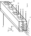
- FIGS 1A and 1B show a schematic illustration of a detector 1. As illustrated by Figure 2 , the detector 1 is suitable for being used with an inspection system 2, e.g. for inspection of cargo 20.
- the detector 1 comprises at least one first scintillator 3 configured to, in response to interaction with a pulse 5 of inspection radiation, re-emit first light 6 in a first wavelength domain.
- the inspection radiation may comprise X-ray radiation as a non-limiting example.
- the inspection may be performed by transmission of successive inspection radiation pulses through the cargo 20 to be inspected.
- the detector 1 comprises at least one second scintillator 4 configured to, in response to interaction with the pulse 5 of inspection radiation, re-emit second light 7 in a second wavelength domain different from the first wavelength domain.
- the detector 1 further comprises at least one first sensor 8 configured to measure (e.g. sense and/or acquire) the first light 6 and not the second light 7 (e.g. the first sensor 8 is configured to be insensitive to and/or not acquire the second light 7).
- first sensor 8 configured to measure (e.g. sense and/or acquire) the first light 6 and not the second light 7 (e.g. the first sensor 8 is configured to be insensitive to and/or not acquire the second light 7).
- the detector 1 Given that the first light 6 produced by the first scintillator 3 and the second light 7 produced by the second scintillator 4 are different, and that the first sensor 8 measures the first light only, the detector 1 according to the present disclosure enables determining energy deposition associated with the pulse 5 at the level of the first scintillator 3 only. As illustrated in Figures 1A and 3A , the first scintillator 3 may have an area ⁇ 1 exposed to the pulse 5 which is a fraction of the total area of the detector 1 exposed to the pulse 5.
- the detector 1 further comprises at least one second sensor 10 configured to measure (e.g. sense and/or acquire) at least the second light 7.
- the second scintillator 4 may have an area ⁇ 2 exposed to the pulse 5 which is equal to ⁇ 1.
- a resolution of an image obtained using a signal associated with the second scintillator 4 and the second sensor 10 may be increased in the (Oz) direction.
- the second scintillator 4 may have an area ⁇ 2 exposed to the pulse 5 which is greater than ⁇ 1.
- the signal associated with the second scintillator 4 and the second sensor 10 will generate a better contrast compared to the signal associated with the first scintillator 3 and the first sensor 8, because the area ⁇ 2 is larger than the area ⁇ 1 and more energy from the pulse 5 is deposited in the second scintillator 4.
- the at least one second sensor 10 is configured not to measure (e.g. to be insensitive to) the first light 6. In that case the signal associated with the second scintillator 4 and the at least one second sensor 10 may be proportional to the energy deposition on the area ⁇ 2. However, in some examples, the at least one second sensor 10 may be configured to measure both the first light 6 and the second light 7. In that case the signal associated with the at least one second sensor 10 may thus be proportional to the energy deposition in the whole detector (i.e. both the areas ⁇ 1 and ⁇ 2).
- the at least one first sensor 8 and the at least one second sensor 10 have each their own electronic channel.
- the inspection system 2 may be mobile and may be transported from a location to another location.
- the system 2 may comprise an automotive vehicle.
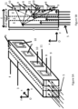
- the inspection system 2 may be configured to inspect the cargo 20 by transmission of successive radiation pulses 5, emitted from an inspection radiation source 13 to at least one detection array 14, through the cargo 20.
- the detection array 14 may comprise a detection line 14 comprising a plurality of detectors 1 according to the disclosure, as illustrated in Figure 8 .
- the array 14 of Figure 8 comprises only three detectors 1. However it should be understood that the array 14 may comprise any number of detectors 1, such as up to 1200 detectors or more as a non-limiting example.
- Figure 2 illustrates that the cargo 20 may be a trailer and/or a boot of a vehicle such as a truck, a van and/or a car, and/or may be a shipping container.
- a vehicle such as a truck, a van and/or a car
- Figure 2 illustrates that the cargo 20 may be a trailer and/or a boot of a vehicle such as a truck, a van and/or a car, and/or may be a shipping container.
- the system 2 may further comprise other types of detectors, such as optional gamma and/or neutrons detectors, e.g., adapted to detect the presence of radioactive gamma and/or neutrons emitting materials within the cargo 20, e.g., simultaneously to the X-ray inspection.
- the system 2 may also comprise an electro-hydraulic boom 15 which can operate in a retracted position in a transport mode (not illustrated in the Figures) and in an inspection position ( Figure 2 ).
- the boom 15 may be operated by hydraulic activators (such as hydraulic cylinders).
- the at least one first sensor 8 comprises a first filter 9 configured to let through the first wavelength domain and inhibit (e.g. block or at least attenuate) the second wavelength domain.
- the at least one second sensor 10 comprises a second filter 11 configured to let through the second wavelength domain and inhibit (e.g. block or at least attenuate) the first wavelength domain.
- the at least one second sensor 10 need not being configured not to measure (e.g. configured to be insensitive to) the first light 6, and, in some examples, the at least one second sensor 10 may be sensitive to both the first light 6 and the second light 7.
- the fact that the at least one second sensor 10 may be sensitive to both the first light 6 and the second light 7 means that the signal associated with the at least one second sensor 10 is greater than that of a sensor sensitive only to the second light 7. This means that the penetration and/or contrast associated with the second sensor 10 is greater.
- the at least one first sensor 8 and/or the at least one second sensor 10 comprises a photodiode.
- the first scintillator 3 comprises an organic and/or an inorganic material.
- the second scintillator 4 comprises an organic and/or an inorganic material.
- organic material include:
- each of the at least one first scintillator 3 is configured to re-emit the first light 6 in the red first wavelength domain
- each of the at least one second scintillator 4 is configured to re-emit the second light 7 in the blue second wavelength domain.
- Other wavelength domains are envisaged.
- the first scintillator 3 may comprise one or more wavelength shifters for re-emitting the first light in the first wavelength domain.
- the second scintillator 4 may comprise one or more wavelength shifters for re-emitting the second light in the second wavelength domain different from the first wavelength domain.
- a dimension ⁇ of the detector in a direction transversal to a direction of extension of a depth of the first scintillator and/or of the second scintillator extending in a direction parallel to a plane of propagation of the inspection radiation may be such that: 1 mm ⁇ ⁇ ⁇ 5 mm .
- D may be such that 10 mm ⁇ D ⁇ 100 mm .
- the at least one first sensor 8 and the at least one second sensor 10 are located on a same side of the at least one first scintillator 3 the at least one second scintillator 4, along the depth D of the first scintillator 3 or along the depth D of the second scintillator 4.
- the at least one first sensor 8 and the at least one second sensor 10 are located on a same side of the at least one first scintillator 3, along the depth D of the first scintillator 3. It should be understood that the device 1 illustrated in Figures 1A and 1B may alternatively comprise at least one first sensor and at least one second sensor located on a side 12 of the at least one second scintillator 4, along the depth D of the second scintillator 4, or on an upper face 16 or a lower face 17.
- the first scintillator 3 is located adjacent the second scintillator 4.
- a dimension e1 of the first scintillator 3 in the direction (Oy) transversal to the depth D of the first scintillator 3 and the second scintillator 4 may be such that: 0.5 mm ⁇ e 1 ⁇ 3.5 mm .
- e1 may be equal to about 1mm.
- a dimension e2 of the second scintillator 4 in the direction (Oy) transversal to the depth D of the first scintillator 3 and of the second scintillator 4 may be such that: 1 mm ⁇ e 2 ⁇ 4.5 mm , and e 2 ⁇ e 1 .
- e2 may be equal to about 4mm.
- e2 is greater than e1 means that the signal associated with the second scintillator 4 and the second sensor 10 is greater than the signal associated with the first scintillator 3 and the first sensor 8. This means that the penetration and/or contrast associated with the second scintillator 4 and the second sensor 10 is greater than the penetration and/or contrast associated with the first scintillator 3 and the first sensor 8.
- the signal associated with the first scintillator 3 and detected by the at least one first sensor 8 is proportional to the energy deposition in the first scintillator 3 only.
- e1 is smaller than e2 means that the resolution associated with the first scintillator 3 and the first sensor 8 is greater than the resolution associated with the second scintillator 4 and the second sensor 10.
- the detector 1 comprises one first scintillator 3 located between two second scintillators 4.
- the dimension e1 of the first scintillator 3 in the direction (Oy) transversal to the depth D of the first scintillator 3 and of the second scintillators 4 is such that: 0.5 mm ⁇ e 1 ⁇ 3.5 mm .
- e1 may be equal to about 1mm.
- the dimension e2 of each of the second scintillators 4 in the direction (Oy) transversal to the depth D of the first scintillator 3 and the second scintillators 4 is such that: 1 mm ⁇ e 2 ⁇ 4 mm .
- e2 may be equal to about 2mm.
- the dimension of the two second scintillators 4 in the direction (Oy) transversal to the depth D of the first scintillator 3 and the second scintillators is thus equal to 2xe2.
- 2xe2 is greater than e1 means that the signal associated with the second scintillators 4 and the second sensors 10 is greater than the signal associated with the first scintillator 3 and the first sensors 8. This means that the penetration and/or contrast associated with the second scintillators 4 and the second sensors 8 is greater than the penetration and/or contrast associated with the first scintillator 3 and the first sensors 8.
- e1 is smaller than 2xe2 means that the resolution associated with the first scintillator 3 and the first sensors 8 is greater than the resolution associated with the second scintillators 4 and the second sensors 10.
- the detector 1 comprises one first scintillator 3 located adjacent one second scintillator 4, in the direction (Oz) transversal to the depth D of the first scintillator 3 and of the second scintillator 4.
- a dimension e1 of the first scintillator 3 in the direction (Oz) transversal to the depth D of the first scintillator 3 and of the second scintillator 4 is such that: 0.5 mm ⁇ e 1 ⁇ 3.5 mm .
- e1 may be equal to about 2.5mm.
- a dimension e2 of the second scintillator 4 in the direction (Oz) transversal to the depth D of the first scintillator 3 and of the second scintillator 4 is such that: 1 mm ⁇ e 2 ⁇ 4 mm .
- e2 may be equal to about 2.5mm.
- the at least one first scintillator 3 has a refractive index
- the at least one second scintillator 4 has a refractive index substantially equal to the refractive index of the first scintillator. Both first light 6 and second light 7 may then exit the first scintillator 3 and the second scintillator 4 to reach the first and second sensors 8 and 10.
- the successive first radiation pulses 5 may comprise at least one of X-ray radiation and/or gamma radiation and/or neutron radiation.
- a method according to the disclosure may comprise:
- the method described above may be performed, at least partly, on a detection device as described above.
- a first light domain and a second light domain have been disclosed. It should be appreciated that embodiments of the disclosure may, additionally or alternatively, use the disclosed light selection to separate an undesirable afterglow from the desired signal to measure (the afterglow may correspond to an undesirable signal which can last several seconds and may deteriorate an obtained image by generating «bleeding» in the image).
- the afterglow may correspond to an undesirable signal which can last several seconds and may deteriorate an obtained image by generating «bleeding» in the image.
- the energy of the X-rays may be comprised between 1MeV and 15MeV, and the dose may be comprised between 2mGy and 20Gy (Gray).
- the power of the X-ray generator may be e.g., between 500keV and 9.0MeV, typically e.g., 2MeV, 3.5MeV, 4MeV, or 6MeV, for a steel penetration capacity e.g., between 150mm to 350mm, typically e.g., 200mm (7.9in).
- the dose may be e.g., between 20mGy and 50mGy.
- the system may also be static with respect to the ground.
- the power of the X-ray generator may be e.g., between 4MeV and 10MeV, typically e.g., 9MeV, for a steel penetration capacity e.g., between 300mm to 450mm, typically e.g., 410mm (16.1in).
- the dose may be 17Gy.
- the inspection radiation generator may comprise sources of other radiation, such as neutrons.
- the inspection radiation generator may also comprise sources which are not adapted to be activated by a power supply, such as radioactive sources, such as using Co60 or Cs137.
Landscapes
- Physics & Mathematics (AREA)
- Life Sciences & Earth Sciences (AREA)
- General Physics & Mathematics (AREA)
- High Energy & Nuclear Physics (AREA)
- Health & Medical Sciences (AREA)
- Molecular Biology (AREA)
- Spectroscopy & Molecular Physics (AREA)
- General Life Sciences & Earth Sciences (AREA)
- Geophysics (AREA)
- Measurement Of Radiation (AREA)
- Analysing Materials By The Use Of Radiation (AREA)
Applications Claiming Priority (2)
| Application Number | Priority Date | Filing Date | Title |
|---|---|---|---|
| GB1704123.7A GB2560552B (en) | 2017-03-15 | 2017-03-15 | Method and apparatus |
| PCT/GB2018/050616 WO2018167466A1 (en) | 2017-03-15 | 2018-03-09 | Method and detector for inspection system |
Publications (2)
| Publication Number | Publication Date |
|---|---|
| EP3596510A1 EP3596510A1 (en) | 2020-01-22 |
| EP3596510B1 true EP3596510B1 (en) | 2024-07-24 |
Family
ID=58605624
Family Applications (1)
| Application Number | Title | Priority Date | Filing Date |
|---|---|---|---|
| EP18714346.6A Active EP3596510B1 (en) | 2017-03-15 | 2018-03-09 | Method and detector for inspection system |
Country Status (6)
| Country | Link |
|---|---|
| US (1) | US11237293B2 (pl) |
| EP (1) | EP3596510B1 (pl) |
| CN (1) | CN110622039B (pl) |
| GB (1) | GB2560552B (pl) |
| PL (1) | PL3596510T3 (pl) |
| WO (1) | WO2018167466A1 (pl) |
Families Citing this family (7)
| Publication number | Priority date | Publication date | Assignee | Title |
|---|---|---|---|---|
| CN113874758B (zh) * | 2019-04-12 | 2025-05-06 | 阿尔克蒂斯辐射探测器有限公司 | 面板辐射检测器 |
| GB2595446B (en) * | 2020-05-18 | 2024-11-27 | Smiths Detection France S A S | Matrix of detectors with staggered columns |
| AU2022226583A1 (en) | 2021-02-23 | 2023-09-07 | Rapiscan Systems, Inc. | Systems and methods for eliminating cross-talk in scanning systems having multiple x-ray sources |
| GB2621502A (en) | 2021-07-13 | 2024-02-14 | Rapiscan Systems Inc | Image inspection systems and methods for integrating third party artificial intelligence platforms |
| GB2634134A (en) | 2022-02-03 | 2025-04-02 | Rapiscan Holdings Inc | Systems and methods for real-time energy and dose monitoring of an X-ray linear accelerator |
| US12474282B2 (en) | 2022-05-20 | 2025-11-18 | Rapiscan Holdings, Inc. | Systems and a method of improved material classification using energy-integrated backscatter detectors |
| GB2641476A (en) | 2023-03-17 | 2025-12-03 | Rapiscan Holdings Inc | Systems and methods for monitoring output energy of a high-energy X-ray source |
Family Cites Families (26)
| Publication number | Priority date | Publication date | Assignee | Title |
|---|---|---|---|---|
| JPH0587935A (ja) * | 1991-09-27 | 1993-04-09 | Fuji Electric Co Ltd | 放射線測定装置 |
| JP3332200B2 (ja) | 1995-11-29 | 2002-10-07 | 日立金属株式会社 | X線ct用放射線検出器 |
| DE19711927A1 (de) * | 1997-03-21 | 1998-09-24 | Siemens Ag | Energieselektive Detektoranordnung |
| JPH11271453A (ja) * | 1998-03-25 | 1999-10-08 | Toshiba Corp | 放射線弁別測定方法および放射線弁別測定装置 |
| JP4060483B2 (ja) * | 1999-03-12 | 2008-03-12 | 株式会社東芝 | 放射線検出器 |
| GB2378112A (en) * | 2001-06-26 | 2003-01-29 | Europ Org For Nuclear Research | A PET scanner with LuAP or LuYAP scintillators |
| DE10224227A1 (de) | 2002-05-31 | 2003-12-18 | Siemens Ag | Röntgendetektor und Verfahren zum Nachweis von Röntgenstrahlung |
| US20060067472A1 (en) * | 2004-09-30 | 2006-03-30 | Possin George E | Method and apparatus for measuring X-ray energy |
| US7335891B2 (en) * | 2005-06-27 | 2008-02-26 | General Electric Company | Gamma and neutron radiation detector |
| CN101365961A (zh) * | 2005-10-05 | 2009-02-11 | 皇家飞利浦电子股份有限公司 | 用于能谱计算机断层摄影成像的多层探测器 |
| US20100224783A1 (en) * | 2005-12-01 | 2010-09-09 | Innovative American Technology Inc. | High performance neutron detector with near zero gamma cross talk |
| US7388208B2 (en) * | 2006-01-11 | 2008-06-17 | Ruvin Deych | Dual energy x-ray detector |
| CN101652677A (zh) * | 2007-04-12 | 2010-02-17 | 皇家飞利浦电子股份有限公司 | 闪烁体的空间增益分布的确定 |
| BRPI0910206A2 (pt) | 2008-06-30 | 2015-09-29 | Koninkl Philips Electronics Nv | sistema de formação de imagem de tomografia computadorizada e método |
| US7965816B2 (en) * | 2008-08-11 | 2011-06-21 | Control Screening, LLC. | Scanning X-ray inspection system using scintillation detection with simultaneous counting and integrating modes |
| JP5588994B2 (ja) * | 2008-11-25 | 2014-09-10 | コーニンクレッカ フィリップス エヌ ヴェ | スペクトルイメージング |
| US8729478B2 (en) * | 2010-06-09 | 2014-05-20 | Carestream Health, Inc. | Dual screen radiographic detector with improved spatial sampling |
| JP2012136667A (ja) * | 2010-12-27 | 2012-07-19 | Tohoku Univ | シンチレータ用発光材料、それを用いたシンチレータ及びそれを用いた放射線検出器並びに放射線検査装置 |
| JP2013127371A (ja) * | 2011-12-16 | 2013-06-27 | Canon Inc | 放射線検出装置 |
| US8866089B2 (en) * | 2011-12-30 | 2014-10-21 | Saint-Gobain Ceramics & Plastics, Inc. | Scintillator pixel array |
| JP5846960B2 (ja) * | 2012-02-24 | 2016-01-20 | 株式会社トクヤマ | 放射線検出器 |
| US9012857B2 (en) * | 2012-05-07 | 2015-04-21 | Koninklijke Philips N.V. | Multi-layer horizontal computed tomography (CT) detector array with at least one thin photosensor array layer disposed between at least two scintillator array layers |
| EP2994777A1 (en) * | 2013-05-10 | 2016-03-16 | Koninklijke Philips N.V. | Large-area scintillator element and radiation detectors and radiation absorption event locating systems using same |
| CN105324683B (zh) * | 2013-06-27 | 2018-10-16 | 万睿视影像有限公司 | 具有嵌入在tft平板中的cmos传感器的x射线成像器 |
| JP2016176727A (ja) * | 2015-03-18 | 2016-10-06 | 株式会社東芝 | 計測装置 |
| US10345479B2 (en) * | 2015-09-16 | 2019-07-09 | Rapiscan Systems, Inc. | Portable X-ray scanner |
-
2017
- 2017-03-15 GB GB1704123.7A patent/GB2560552B/en active Active
-
2018
- 2018-03-09 WO PCT/GB2018/050616 patent/WO2018167466A1/en not_active Ceased
- 2018-03-09 US US16/493,820 patent/US11237293B2/en active Active
- 2018-03-09 CN CN201880027063.2A patent/CN110622039B/zh active Active
- 2018-03-09 EP EP18714346.6A patent/EP3596510B1/en active Active
- 2018-03-09 PL PL18714346.6T patent/PL3596510T3/pl unknown
Also Published As
| Publication number | Publication date |
|---|---|
| GB2560552B (en) | 2020-09-09 |
| WO2018167466A1 (en) | 2018-09-20 |
| US11237293B2 (en) | 2022-02-01 |
| CN110622039A (zh) | 2019-12-27 |
| CN110622039B (zh) | 2023-10-24 |
| EP3596510A1 (en) | 2020-01-22 |
| PL3596510T4 (pl) | 2025-01-27 |
| GB2560552A (en) | 2018-09-19 |
| GB201704123D0 (en) | 2017-04-26 |
| PL3596510T3 (pl) | 2025-01-27 |
| US20200132878A1 (en) | 2020-04-30 |
Similar Documents
| Publication | Publication Date | Title |
|---|---|---|
| EP3596510B1 (en) | Method and detector for inspection system | |
| US8457274B2 (en) | System and methods for intrapulse multi-energy and adaptive multi-energy X-ray cargo inspection | |
| EP3491425B1 (en) | Inspection system with a matrix and method | |
| US9329301B2 (en) | Radiation detecting device | |
| US20180259462A1 (en) | Non-destructive inspection device and method | |
| EP3365665B1 (en) | High dynamic range radiographic imaging system | |
| US20090080596A1 (en) | Radiographic equipment | |
| US20090283690A1 (en) | System and methods for detecting concealed nuclear material in cargo | |
| GB2555564A (en) | Scatter imaging | |
| JPH11194170A (ja) | 放射性物質検査装置及び放射性廃棄物検査システム | |
| US20110193711A1 (en) | Method and device for detecting the presence, in a load, of objects suspected of containing at least one material having a given atomic weight | |
| Gerl et al. | High-resolution gamma backscatter imaging for technical applications | |
| CN110199209B (zh) | 散射成像 | |
| CN110121666A (zh) | 具有辐射源的检查系统和方法 | |
| Kolkoori et al. | High energy X-ray imaging technology for the detection of dangerous materials in air freight containers | |
| EP3559708B1 (en) | Scanning apparatus and method for the detection of objects concealed in cargo | |
| KR20240079010A (ko) | 산란엑스선 영상과 방사선 동시측정용 복합 검색시스템 | |
| Eberhardt et al. | Fast-neutron/gamma-ray radiography scanner for the detection of contraband in air cargo containers | |
| Osipov et al. | Performance evaluation of cargo inspection | |
| Van Liew et al. | A dual-energy transmission detector for vehicle scanning using wavelength-shifting fibers |
Legal Events
| Date | Code | Title | Description |
|---|---|---|---|
| STAA | Information on the status of an ep patent application or granted ep patent |
Free format text: STATUS: UNKNOWN |
|
| STAA | Information on the status of an ep patent application or granted ep patent |
Free format text: STATUS: THE INTERNATIONAL PUBLICATION HAS BEEN MADE |
|
| PUAI | Public reference made under article 153(3) epc to a published international application that has entered the european phase |
Free format text: ORIGINAL CODE: 0009012 |
|
| STAA | Information on the status of an ep patent application or granted ep patent |
Free format text: STATUS: REQUEST FOR EXAMINATION WAS MADE |
|
| 17P | Request for examination filed |
Effective date: 20191002 |
|
| AK | Designated contracting states |
Kind code of ref document: A1 Designated state(s): AL AT BE BG CH CY CZ DE DK EE ES FI FR GB GR HR HU IE IS IT LI LT LU LV MC MK MT NL NO PL PT RO RS SE SI SK SM TR |
|
| AX | Request for extension of the european patent |
Extension state: BA ME |
|
| DAV | Request for validation of the european patent (deleted) | ||
| DAX | Request for extension of the european patent (deleted) | ||
| STAA | Information on the status of an ep patent application or granted ep patent |
Free format text: STATUS: EXAMINATION IS IN PROGRESS |
|
| 17Q | First examination report despatched |
Effective date: 20220411 |
|
| GRAP | Despatch of communication of intention to grant a patent |
Free format text: ORIGINAL CODE: EPIDOSNIGR1 |
|
| STAA | Information on the status of an ep patent application or granted ep patent |
Free format text: STATUS: GRANT OF PATENT IS INTENDED |
|
| INTG | Intention to grant announced |
Effective date: 20240221 |
|
| GRAS | Grant fee paid |
Free format text: ORIGINAL CODE: EPIDOSNIGR3 |
|
| GRAA | (expected) grant |
Free format text: ORIGINAL CODE: 0009210 |
|
| STAA | Information on the status of an ep patent application or granted ep patent |
Free format text: STATUS: THE PATENT HAS BEEN GRANTED |
|
| REG | Reference to a national code |
Ref country code: DE Ref legal event code: R081 Ref document number: 602018072133 Country of ref document: DE Owner name: SMITHS DETECTION FRANCE S.A.S., FR Free format text: FORMER OWNER: SMITHS DETECTION FRANCE S.A.S., VITRY-SUR-SEIN, FR |
|
| AK | Designated contracting states |
Kind code of ref document: B1 Designated state(s): AL AT BE BG CH CY CZ DE DK EE ES FI FR GB GR HR HU IE IS IT LI LT LU LV MC MK MT NL NO PL PT RO RS SE SI SK SM TR |
|
| RAP3 | Party data changed (applicant data changed or rights of an application transferred) |
Owner name: SMITHS DETECTION FRANCE S.A.S. |
|
| REG | Reference to a national code |
Ref country code: GB Ref legal event code: FG4D |
|
| RIN1 | Information on inventor provided before grant (corrected) |
Inventor name: FAUGIER, JEAN-MICHEL Inventor name: JEGOU, GUILLAUME |
|
| REG | Reference to a national code |
Ref country code: CH Ref legal event code: EP |
|
| REG | Reference to a national code |
Ref country code: IE Ref legal event code: FG4D Ref country code: DE Ref legal event code: R096 Ref document number: 602018072133 Country of ref document: DE |
|
| REG | Reference to a national code |
Ref country code: NL Ref legal event code: FP |
|
| REG | Reference to a national code |
Ref country code: LT Ref legal event code: MG9D |
|
| PG25 | Lapsed in a contracting state [announced via postgrant information from national office to epo] |
Ref country code: PT Free format text: LAPSE BECAUSE OF FAILURE TO SUBMIT A TRANSLATION OF THE DESCRIPTION OR TO PAY THE FEE WITHIN THE PRESCRIBED TIME-LIMIT Effective date: 20241125 |
|
| REG | Reference to a national code |
Ref country code: AT Ref legal event code: MK05 Ref document number: 1706811 Country of ref document: AT Kind code of ref document: T Effective date: 20240724 |
|
| P01 | Opt-out of the competence of the unified patent court (upc) registered |
Free format text: CASE NUMBER: APP_62053/2024 Effective date: 20241120 |
|
| PG25 | Lapsed in a contracting state [announced via postgrant information from national office to epo] |
Ref country code: PT Free format text: LAPSE BECAUSE OF FAILURE TO SUBMIT A TRANSLATION OF THE DESCRIPTION OR TO PAY THE FEE WITHIN THE PRESCRIBED TIME-LIMIT Effective date: 20241125 |
|
| PG25 | Lapsed in a contracting state [announced via postgrant information from national office to epo] |
Ref country code: NO Free format text: LAPSE BECAUSE OF FAILURE TO SUBMIT A TRANSLATION OF THE DESCRIPTION OR TO PAY THE FEE WITHIN THE PRESCRIBED TIME-LIMIT Effective date: 20241024 |
|
| PG25 | Lapsed in a contracting state [announced via postgrant information from national office to epo] |
Ref country code: FI Free format text: LAPSE BECAUSE OF FAILURE TO SUBMIT A TRANSLATION OF THE DESCRIPTION OR TO PAY THE FEE WITHIN THE PRESCRIBED TIME-LIMIT Effective date: 20240724 Ref country code: GR Free format text: LAPSE BECAUSE OF FAILURE TO SUBMIT A TRANSLATION OF THE DESCRIPTION OR TO PAY THE FEE WITHIN THE PRESCRIBED TIME-LIMIT Effective date: 20241025 |
|
| PG25 | Lapsed in a contracting state [announced via postgrant information from national office to epo] |
Ref country code: BG Free format text: LAPSE BECAUSE OF FAILURE TO SUBMIT A TRANSLATION OF THE DESCRIPTION OR TO PAY THE FEE WITHIN THE PRESCRIBED TIME-LIMIT Effective date: 20240724 |
|
| PGFP | Annual fee paid to national office [announced via postgrant information from national office to epo] |
Ref country code: FR Payment date: 20241231 Year of fee payment: 8 |
|
| PG25 | Lapsed in a contracting state [announced via postgrant information from national office to epo] |
Ref country code: LV Free format text: LAPSE BECAUSE OF FAILURE TO SUBMIT A TRANSLATION OF THE DESCRIPTION OR TO PAY THE FEE WITHIN THE PRESCRIBED TIME-LIMIT Effective date: 20240724 |
|
| PG25 | Lapsed in a contracting state [announced via postgrant information from national office to epo] |
Ref country code: IS Free format text: LAPSE BECAUSE OF FAILURE TO SUBMIT A TRANSLATION OF THE DESCRIPTION OR TO PAY THE FEE WITHIN THE PRESCRIBED TIME-LIMIT Effective date: 20241124 Ref country code: AT Free format text: LAPSE BECAUSE OF FAILURE TO SUBMIT A TRANSLATION OF THE DESCRIPTION OR TO PAY THE FEE WITHIN THE PRESCRIBED TIME-LIMIT Effective date: 20240724 |
|
| PG25 | Lapsed in a contracting state [announced via postgrant information from national office to epo] |
Ref country code: HR Free format text: LAPSE BECAUSE OF FAILURE TO SUBMIT A TRANSLATION OF THE DESCRIPTION OR TO PAY THE FEE WITHIN THE PRESCRIBED TIME-LIMIT Effective date: 20240724 |
|
| PG25 | Lapsed in a contracting state [announced via postgrant information from national office to epo] |
Ref country code: ES Free format text: LAPSE BECAUSE OF FAILURE TO SUBMIT A TRANSLATION OF THE DESCRIPTION OR TO PAY THE FEE WITHIN THE PRESCRIBED TIME-LIMIT Effective date: 20240724 Ref country code: RS Free format text: LAPSE BECAUSE OF FAILURE TO SUBMIT A TRANSLATION OF THE DESCRIPTION OR TO PAY THE FEE WITHIN THE PRESCRIBED TIME-LIMIT Effective date: 20241024 |
|
| PG25 | Lapsed in a contracting state [announced via postgrant information from national office to epo] |
Ref country code: RS Free format text: LAPSE BECAUSE OF FAILURE TO SUBMIT A TRANSLATION OF THE DESCRIPTION OR TO PAY THE FEE WITHIN THE PRESCRIBED TIME-LIMIT Effective date: 20241024 Ref country code: NO Free format text: LAPSE BECAUSE OF FAILURE TO SUBMIT A TRANSLATION OF THE DESCRIPTION OR TO PAY THE FEE WITHIN THE PRESCRIBED TIME-LIMIT Effective date: 20241024 Ref country code: LV Free format text: LAPSE BECAUSE OF FAILURE TO SUBMIT A TRANSLATION OF THE DESCRIPTION OR TO PAY THE FEE WITHIN THE PRESCRIBED TIME-LIMIT Effective date: 20240724 Ref country code: IS Free format text: LAPSE BECAUSE OF FAILURE TO SUBMIT A TRANSLATION OF THE DESCRIPTION OR TO PAY THE FEE WITHIN THE PRESCRIBED TIME-LIMIT Effective date: 20241124 Ref country code: HR Free format text: LAPSE BECAUSE OF FAILURE TO SUBMIT A TRANSLATION OF THE DESCRIPTION OR TO PAY THE FEE WITHIN THE PRESCRIBED TIME-LIMIT Effective date: 20240724 Ref country code: GR Free format text: LAPSE BECAUSE OF FAILURE TO SUBMIT A TRANSLATION OF THE DESCRIPTION OR TO PAY THE FEE WITHIN THE PRESCRIBED TIME-LIMIT Effective date: 20241025 Ref country code: FI Free format text: LAPSE BECAUSE OF FAILURE TO SUBMIT A TRANSLATION OF THE DESCRIPTION OR TO PAY THE FEE WITHIN THE PRESCRIBED TIME-LIMIT Effective date: 20240724 Ref country code: ES Free format text: LAPSE BECAUSE OF FAILURE TO SUBMIT A TRANSLATION OF THE DESCRIPTION OR TO PAY THE FEE WITHIN THE PRESCRIBED TIME-LIMIT Effective date: 20240724 Ref country code: BG Free format text: LAPSE BECAUSE OF FAILURE TO SUBMIT A TRANSLATION OF THE DESCRIPTION OR TO PAY THE FEE WITHIN THE PRESCRIBED TIME-LIMIT Effective date: 20240724 Ref country code: AT Free format text: LAPSE BECAUSE OF FAILURE TO SUBMIT A TRANSLATION OF THE DESCRIPTION OR TO PAY THE FEE WITHIN THE PRESCRIBED TIME-LIMIT Effective date: 20240724 |
|
| PGFP | Annual fee paid to national office [announced via postgrant information from national office to epo] |
Ref country code: NL Payment date: 20250106 Year of fee payment: 8 |
|
| PGFP | Annual fee paid to national office [announced via postgrant information from national office to epo] |
Ref country code: DE Payment date: 20241231 Year of fee payment: 8 |
|
| PG25 | Lapsed in a contracting state [announced via postgrant information from national office to epo] |
Ref country code: SM Free format text: LAPSE BECAUSE OF FAILURE TO SUBMIT A TRANSLATION OF THE DESCRIPTION OR TO PAY THE FEE WITHIN THE PRESCRIBED TIME-LIMIT Effective date: 20240724 Ref country code: RO Free format text: LAPSE BECAUSE OF FAILURE TO SUBMIT A TRANSLATION OF THE DESCRIPTION OR TO PAY THE FEE WITHIN THE PRESCRIBED TIME-LIMIT Effective date: 20240724 Ref country code: DK Free format text: LAPSE BECAUSE OF FAILURE TO SUBMIT A TRANSLATION OF THE DESCRIPTION OR TO PAY THE FEE WITHIN THE PRESCRIBED TIME-LIMIT Effective date: 20240724 |
|
| PG25 | Lapsed in a contracting state [announced via postgrant information from national office to epo] |
Ref country code: EE Free format text: LAPSE BECAUSE OF FAILURE TO SUBMIT A TRANSLATION OF THE DESCRIPTION OR TO PAY THE FEE WITHIN THE PRESCRIBED TIME-LIMIT Effective date: 20240724 |
|
| PG25 | Lapsed in a contracting state [announced via postgrant information from national office to epo] |
Ref country code: CZ Free format text: LAPSE BECAUSE OF FAILURE TO SUBMIT A TRANSLATION OF THE DESCRIPTION OR TO PAY THE FEE WITHIN THE PRESCRIBED TIME-LIMIT Effective date: 20240724 |
|
| PGFP | Annual fee paid to national office [announced via postgrant information from national office to epo] |
Ref country code: PL Payment date: 20250113 Year of fee payment: 8 |
|
| REG | Reference to a national code |
Ref country code: DE Ref legal event code: R097 Ref document number: 602018072133 Country of ref document: DE |
|
| PG25 | Lapsed in a contracting state [announced via postgrant information from national office to epo] |
Ref country code: SK Free format text: LAPSE BECAUSE OF FAILURE TO SUBMIT A TRANSLATION OF THE DESCRIPTION OR TO PAY THE FEE WITHIN THE PRESCRIBED TIME-LIMIT Effective date: 20240724 |
|
| PGFP | Annual fee paid to national office [announced via postgrant information from national office to epo] |
Ref country code: IT Payment date: 20250211 Year of fee payment: 8 Ref country code: GB Payment date: 20250102 Year of fee payment: 8 |
|
| PLBE | No opposition filed within time limit |
Free format text: ORIGINAL CODE: 0009261 |
|
| STAA | Information on the status of an ep patent application or granted ep patent |
Free format text: STATUS: NO OPPOSITION FILED WITHIN TIME LIMIT |
|
| 26N | No opposition filed |
Effective date: 20250425 |
|
| PG25 | Lapsed in a contracting state [announced via postgrant information from national office to epo] |
Ref country code: SE Free format text: LAPSE BECAUSE OF FAILURE TO SUBMIT A TRANSLATION OF THE DESCRIPTION OR TO PAY THE FEE WITHIN THE PRESCRIBED TIME-LIMIT Effective date: 20240724 |
|
| PG25 | Lapsed in a contracting state [announced via postgrant information from national office to epo] |
Ref country code: MC Free format text: LAPSE BECAUSE OF FAILURE TO SUBMIT A TRANSLATION OF THE DESCRIPTION OR TO PAY THE FEE WITHIN THE PRESCRIBED TIME-LIMIT Effective date: 20240724 |
|
| REG | Reference to a national code |
Ref country code: CH Ref legal event code: H13 Free format text: ST27 STATUS EVENT CODE: U-0-0-H10-H13 (AS PROVIDED BY THE NATIONAL OFFICE) Effective date: 20251023 |
|
| PG25 | Lapsed in a contracting state [announced via postgrant information from national office to epo] |
Ref country code: LU Free format text: LAPSE BECAUSE OF NON-PAYMENT OF DUE FEES Effective date: 20250309 |