EP3595592B1 - Vorrichtung und verfahren zur generativen fertigung - Google Patents
Vorrichtung und verfahren zur generativen fertigung Download PDFInfo
- Publication number
- EP3595592B1 EP3595592B1 EP18712977.0A EP18712977A EP3595592B1 EP 3595592 B1 EP3595592 B1 EP 3595592B1 EP 18712977 A EP18712977 A EP 18712977A EP 3595592 B1 EP3595592 B1 EP 3595592B1
- Authority
- EP
- European Patent Office
- Prior art keywords
- fluid
- laser
- interaction
- printing apparatus
- additive printing
- Prior art date
- Legal status (The legal status is an assumption and is not a legal conclusion. Google has not performed a legal analysis and makes no representation as to the accuracy of the status listed.)
- Active
Links
Images







Classifications
-
- A—HUMAN NECESSITIES
- A61—MEDICAL OR VETERINARY SCIENCE; HYGIENE
- A61F—FILTERS IMPLANTABLE INTO BLOOD VESSELS; PROSTHESES; DEVICES PROVIDING PATENCY TO, OR PREVENTING COLLAPSING OF, TUBULAR STRUCTURES OF THE BODY, e.g. STENTS; ORTHOPAEDIC, NURSING OR CONTRACEPTIVE DEVICES; FOMENTATION; TREATMENT OR PROTECTION OF EYES OR EARS; BANDAGES, DRESSINGS OR ABSORBENT PADS; FIRST-AID KITS
- A61F2/00—Filters implantable into blood vessels; Prostheses, i.e. artificial substitutes or replacements for parts of the body; Appliances for connecting them with the body; Devices providing patency to, or preventing collapsing of, tubular structures of the body, e.g. stents
- A61F2/50—Prostheses not implantable in the body
- A61F2/5044—Designing or manufacturing processes
-
- C—CHEMISTRY; METALLURGY
- C12—BIOCHEMISTRY; BEER; SPIRITS; WINE; VINEGAR; MICROBIOLOGY; ENZYMOLOGY; MUTATION OR GENETIC ENGINEERING
- C12M—APPARATUS FOR ENZYMOLOGY OR MICROBIOLOGY; APPARATUS FOR CULTURING MICROORGANISMS FOR PRODUCING BIOMASS, FOR GROWING CELLS OR FOR OBTAINING FERMENTATION OR METABOLIC PRODUCTS, i.e. BIOREACTORS OR FERMENTERS
- C12M33/00—Means for introduction, transport, positioning, extraction, harvesting, peeling or sampling of biological material in or from the apparatus
-
- C—CHEMISTRY; METALLURGY
- C12—BIOCHEMISTRY; BEER; SPIRITS; WINE; VINEGAR; MICROBIOLOGY; ENZYMOLOGY; MUTATION OR GENETIC ENGINEERING
- C12M—APPARATUS FOR ENZYMOLOGY OR MICROBIOLOGY; APPARATUS FOR CULTURING MICROORGANISMS FOR PRODUCING BIOMASS, FOR GROWING CELLS OR FOR OBTAINING FERMENTATION OR METABOLIC PRODUCTS, i.e. BIOREACTORS OR FERMENTERS
- C12M21/00—Bioreactors or fermenters specially adapted for specific uses
- C12M21/08—Bioreactors or fermenters specially adapted for specific uses for producing artificial tissue or for ex-vivo cultivation of tissue
-
- A—HUMAN NECESSITIES
- A61—MEDICAL OR VETERINARY SCIENCE; HYGIENE
- A61F—FILTERS IMPLANTABLE INTO BLOOD VESSELS; PROSTHESES; DEVICES PROVIDING PATENCY TO, OR PREVENTING COLLAPSING OF, TUBULAR STRUCTURES OF THE BODY, e.g. STENTS; ORTHOPAEDIC, NURSING OR CONTRACEPTIVE DEVICES; FOMENTATION; TREATMENT OR PROTECTION OF EYES OR EARS; BANDAGES, DRESSINGS OR ABSORBENT PADS; FIRST-AID KITS
- A61F2/00—Filters implantable into blood vessels; Prostheses, i.e. artificial substitutes or replacements for parts of the body; Appliances for connecting them with the body; Devices providing patency to, or preventing collapsing of, tubular structures of the body, e.g. stents
- A61F2/02—Prostheses implantable into the body
-
- A—HUMAN NECESSITIES
- A61—MEDICAL OR VETERINARY SCIENCE; HYGIENE
- A61L—METHODS OR APPARATUS FOR STERILISING MATERIALS OR OBJECTS IN GENERAL; DISINFECTION, STERILISATION OR DEODORISATION OF AIR; CHEMICAL ASPECTS OF BANDAGES, DRESSINGS, ABSORBENT PADS OR SURGICAL ARTICLES; MATERIALS FOR BANDAGES, DRESSINGS, ABSORBENT PADS OR SURGICAL ARTICLES
- A61L27/00—Materials for grafts or prostheses or for coating grafts or prostheses
- A61L27/36—Materials for grafts or prostheses or for coating grafts or prostheses containing ingredients of undetermined constitution or reaction products thereof, e.g. transplant tissue, natural bone, extracellular matrix
- A61L27/38—Materials for grafts or prostheses or for coating grafts or prostheses containing ingredients of undetermined constitution or reaction products thereof, e.g. transplant tissue, natural bone, extracellular matrix containing added animal cells
-
- B—PERFORMING OPERATIONS; TRANSPORTING
- B29—WORKING OF PLASTICS; WORKING OF SUBSTANCES IN A PLASTIC STATE IN GENERAL
- B29C—SHAPING OR JOINING OF PLASTICS; SHAPING OF MATERIAL IN A PLASTIC STATE, NOT OTHERWISE PROVIDED FOR; AFTER-TREATMENT OF THE SHAPED PRODUCTS, e.g. REPAIRING
- B29C64/00—Additive manufacturing, i.e. manufacturing of three-dimensional [3D] objects by additive deposition, additive agglomeration or additive layering, e.g. by 3D printing, stereolithography or selective laser sintering
- B29C64/10—Processes of additive manufacturing
- B29C64/106—Processes of additive manufacturing using only liquids or viscous materials, e.g. depositing a continuous bead of viscous material
- B29C64/112—Processes of additive manufacturing using only liquids or viscous materials, e.g. depositing a continuous bead of viscous material using individual droplets, e.g. from jetting heads
-
- B—PERFORMING OPERATIONS; TRANSPORTING
- B33—ADDITIVE MANUFACTURING TECHNOLOGY
- B33Y—ADDITIVE MANUFACTURING, i.e. MANUFACTURING OF THREE-DIMENSIONAL [3D] OBJECTS BY ADDITIVE DEPOSITION, ADDITIVE AGGLOMERATION OR ADDITIVE LAYERING, e.g. BY 3D PRINTING, STEREOLITHOGRAPHY OR SELECTIVE LASER SINTERING
- B33Y10/00—Processes of additive manufacturing
-
- B—PERFORMING OPERATIONS; TRANSPORTING
- B33—ADDITIVE MANUFACTURING TECHNOLOGY
- B33Y—ADDITIVE MANUFACTURING, i.e. MANUFACTURING OF THREE-DIMENSIONAL [3D] OBJECTS BY ADDITIVE DEPOSITION, ADDITIVE AGGLOMERATION OR ADDITIVE LAYERING, e.g. BY 3D PRINTING, STEREOLITHOGRAPHY OR SELECTIVE LASER SINTERING
- B33Y40/00—Auxiliary operations or equipment, e.g. for material handling
-
- B—PERFORMING OPERATIONS; TRANSPORTING
- B41—PRINTING; LINING MACHINES; TYPEWRITERS; STAMPS
- B41J—TYPEWRITERS; SELECTIVE PRINTING MECHANISMS, i.e. MECHANISMS PRINTING OTHERWISE THAN FROM A FORME; CORRECTION OF TYPOGRAPHICAL ERRORS
- B41J2/00—Typewriters or selective printing mechanisms characterised by the printing or marking process for which they are designed
- B41J2/005—Typewriters or selective printing mechanisms characterised by the printing or marking process for which they are designed characterised by bringing liquid or particles selectively into contact with a printing material
- B41J2/01—Ink jet
- B41J2/135—Nozzles
- B41J2/14—Structure thereof only for on-demand ink jet heads
- B41J2/14016—Structure of bubble jet print heads
- B41J2/14088—Structure of heating means
- B41J2/14104—Laser or electron beam heating the ink
-
- B—PERFORMING OPERATIONS; TRANSPORTING
- B41—PRINTING; LINING MACHINES; TYPEWRITERS; STAMPS
- B41J—TYPEWRITERS; SELECTIVE PRINTING MECHANISMS, i.e. MECHANISMS PRINTING OTHERWISE THAN FROM A FORME; CORRECTION OF TYPOGRAPHICAL ERRORS
- B41J2/00—Typewriters or selective printing mechanisms characterised by the printing or marking process for which they are designed
- B41J2/435—Typewriters or selective printing mechanisms characterised by the printing or marking process for which they are designed characterised by selective application of radiation to a printing material or impression-transfer material
-
- B—PERFORMING OPERATIONS; TRANSPORTING
- B41—PRINTING; LINING MACHINES; TYPEWRITERS; STAMPS
- B41J—TYPEWRITERS; SELECTIVE PRINTING MECHANISMS, i.e. MECHANISMS PRINTING OTHERWISE THAN FROM A FORME; CORRECTION OF TYPOGRAPHICAL ERRORS
- B41J2/00—Typewriters or selective printing mechanisms characterised by the printing or marking process for which they are designed
- B41J2/435—Typewriters or selective printing mechanisms characterised by the printing or marking process for which they are designed characterised by selective application of radiation to a printing material or impression-transfer material
- B41J2/44—Typewriters or selective printing mechanisms characterised by the printing or marking process for which they are designed characterised by selective application of radiation to a printing material or impression-transfer material using single radiation source per colour, e.g. lighting beams or shutter arrangements
- B41J2/442—Typewriters or selective printing mechanisms characterised by the printing or marking process for which they are designed characterised by selective application of radiation to a printing material or impression-transfer material using single radiation source per colour, e.g. lighting beams or shutter arrangements using lasers
-
- A—HUMAN NECESSITIES
- A61—MEDICAL OR VETERINARY SCIENCE; HYGIENE
- A61F—FILTERS IMPLANTABLE INTO BLOOD VESSELS; PROSTHESES; DEVICES PROVIDING PATENCY TO, OR PREVENTING COLLAPSING OF, TUBULAR STRUCTURES OF THE BODY, e.g. STENTS; ORTHOPAEDIC, NURSING OR CONTRACEPTIVE DEVICES; FOMENTATION; TREATMENT OR PROTECTION OF EYES OR EARS; BANDAGES, DRESSINGS OR ABSORBENT PADS; FIRST-AID KITS
- A61F2240/00—Manufacturing or designing of prostheses classified in groups A61F2/00 - A61F2/26 or A61F2/82 or A61F9/00 or A61F11/00 or subgroups thereof
- A61F2240/001—Designing or manufacturing processes
- A61F2240/002—Designing or making customized prostheses
-
- B—PERFORMING OPERATIONS; TRANSPORTING
- B33—ADDITIVE MANUFACTURING TECHNOLOGY
- B33Y—ADDITIVE MANUFACTURING, i.e. MANUFACTURING OF THREE-DIMENSIONAL [3D] OBJECTS BY ADDITIVE DEPOSITION, ADDITIVE AGGLOMERATION OR ADDITIVE LAYERING, e.g. BY 3D PRINTING, STEREOLITHOGRAPHY OR SELECTIVE LASER SINTERING
- B33Y80/00—Products made by additive manufacturing
Definitions
- the present invention relates to the field of laser-assisted three-dimensional additive printing and more particularly, but not limited to bioprinting.
- Laser-assisted three-dimensional additive printing consists in projecting particles towards a target by a jet produced by the local vaporization of a substrate providing kinetic energy to a transferable particle or an aggregate of particles contained in a carrier fluid.
- the transferable particles can originate from a pulverulent material carried by a liquid substrate, or from a liquid transferable material.
- They can be metallic in nature, inorganic compounds, or even polymers or biomaterials.
- They can also consist of biological particles, for example living cells.
- the present invention relates to the field of bioprinting carried out by a computer-assisted transfer process for the modeling and assembly of living and non-living materials with a prescribed organization in 2D or 3D in order to produce structures three-dimensional, including bioengineered structures used in regenerative medicine, pharmacology, and cell biology studies.
- Tissue engineering aims to design and develop substitute solutions that are biologically capable of replacing, restoring or maintaining the functions of native tissue, or even of an organ.
- An example is described in the article Griffith, LG, & Naughton, G. (2002). Tissue engineering-current challenges and expanding opportunities. Science, 295 (5557), 1009-1014 .
- the patent is known in the state of the art WO2016097619 describing a method of printing at least one ink, said method comprising a step of focusing a laser beam so as to generate a cavity in an ink film, a step of forming at least one droplet of ink from a free surface of the ink film and a step of depositing said droplet on a depositing surface of a receiving substrate positioned at a given distance (L) from the film, characterized in that the laser beam is oriented against the gravitational force (G), the free surface of the film being oriented upwards towards the deposit surface placed above the ink film.
- G gravitational force
- This system comprises a reservoir comprising at least one opening.
- An energy source configured to deliver energy to a donor material within said reservoir.
- This system allows the deposition of material by induced forward transfer by laser without any need for a donor substrate. Also disclosed are methods of substrateless, local donor laser induced forward transfer.
- a secondary problem that the invention aims to remedy by some of its variants concerns the abandonment of the interaction of the laser with a sacrificial layer, for example a gold coating.
- the jet formed by a laser exciting this layer causes the transfer of material from this layer which can lead to problems of toxicity, of projection of particles other than the particles to to transfer.
- the term “inhomogeneity of the bioink film” means any zone of the film having specific local characteristics in terms of composition: particles, biochemical species (growth factor, molecules, ions), biomaterials.
- the solution consists in making the inhomogeneities of the film of fluid positioned in the laser interaction zone during the three-dimensional additive printing assisted by laser. It also consists in allowing the said interaction zone to be filled in a repeated and controlled manner by the fluid.
- such a solution requires the establishment of a laser printing process not using a sacrificial layer for the generation of the jets of material which in fact implies a laser - material interaction which has place directly in the fluid.
- the process for generating the cavitation bubble and then the jet of material will be totally different from the general prior art.
- the invention allows the use of imaging means correlated with laser shots in order to target inhomogeneities in the fluid in a controlled manner.
- the interaction zone must be based on a material transparent both to the laser and to the image acquisition means.
- This blade defines an area with a preferably flat bottom, positioned to allow interaction with the energetic excitation beam, this area being surrounded by a border having an inlet orifice and an outlet orifice, to ensure the presence in this zone of interaction with the energetic excitation means of a film which can be transiently static, deposited on the zone, and at other times formed by a circulation of the fluid ensuring the renewal of the transferable particles and the relative displacement to the axis of energy excitation.
- the blades of the prior art comprising a static coating of an ink, requiring the blade to be changed after each use, which does not make it possible to optimize the use of the transferable elements.
- the invention also relates to a method of additive printing by an equipment comprising an orientable energetic excitation means to produce a point interaction with a fluid covering a blade, in order to cause a jet directed towards a target, said fluid being constituted by a liquid vector containing transferable inhomogeneities (particles, or biomaterials or chemical species) or by a transferable liquid biomaterial, characterized in that said fluid forms a liquid film with a thickness of less than 500 ⁇ m circulating between a duct of inlet (7) and an outlet duct of a blade having at least one zone allowing interaction with the laser, and into which at least one entrance (7) opens.
- the energy level per pulse is controlled by a computer as a function of the result of measurement of the characteristics of the fluid present in the interaction zone, said measurements comprising the particle density, and / or the viscosity, and / or the thickness of the film.
- the figure 1 represents a first variant embodiment of a device, implementing an excitation by a focused laser beam generating a pulse (1).
- a blade (2) made of glass or transparent material defines a cavity (3) in which circulates a carrier fluid (4) containing transferable particles (5).
- the depth of this cavity is less than 500 ⁇ m and preferably 50 to 100 ⁇ m thick, thus avoiding sedimentation phenomena in the cavity (3).
- This cavity (3) is formed by molding, machining, blowing (glass) or even by 3D printing (FDM, SLS, SLA, DLP, DMLS, EBM, CLIP, MultiJet, etc.) and has a circular or rectangular section. , or oval, or other geometric shapes.
- Its transverse surface (6) defines a working area which can be scanned by the laser beam (1) and visualized on a sensor via an optical retro-beam.
- the carrier fluid (4) pushed by a pumping system (15), enters the cavity (3) through an inlet opening (7) connected to a supply duct (8) itself connected to a reservoir of 'supply (14), and is evacuated via an outlet port (9) to an evacuation and / or suction duct (10).
- the discharge and / or suction line (10) opens into a recovery tank (13) containing the carrier fluid (4) loaded with transferable particles (5).
- a pump (15) circulates the carrier fluid (4) loaded with transferable particles (5).
- the supply tank (14) and the recovery tank (13) can be separate or else form a single tank in the event that it is desired to recirculate the same fluid in the system several times. In this configuration, the advantage is to maximize the number of particles printed in the circulating fluid.
- the system comprises several sets of reservoirs (14 and 13), each containing a carrier fluid loaded with inhomogeneities of different natures.
- a valve makes it possible to select one of the reservoirs, to allow the deposition of particles of different natures and the formation of differentiated layers on the target (11).
- the flow rate of carrier fluid (4) is adjusted to ensure the movement of the working area of the transferable particles (5) at a speed allowing selection by appropriate means (imaging, spectroscopy, ...) and activate those which are selected. by laser fire.
- the target (11) is movable in an X, Y plane parallel to the bottom (6) of the cavity (3) to determine the point of deposit of the transferred particle (12) and possibly in a perpendicular direction, to adjust the distance traveled by the particle (5) to be transferred. In this case, it is possible to modulate the size of the droplets deposited on the print receiving substrate.
- the figure 2 shows a sectional view of the device completed with the optical system.
- This optical system consists of two angularly oscillating mirrors (of the galvanometer type) (20), making it possible to scan the laser firing zone, and by a first optical unit (21) consisting of a scanning lens, of the F- lens type. Theta, making it possible to form a laser spot whose diameter on the work surface is as small and as constant as possible.
- This first optical unit (21) is constituted in a known manner by a system of several lenses.
- the optical system Upstream of the scanning mirrors (20), the optical system comprises a laser source (22), the beam of which is returned to the scanning mirrors (20) by a dichroic mirror (23).
- a second optical unit (24) forms an image of the working area (25) by the retro-beam passing through the dichroic mirror (23), on a sensor (26).
- the figure 3 shows a top view of a variant of a blade (2) according to the invention.
- It comprises three circuits formed of three parallel cavities (30, 31, 32), each extending between a supply duct (respectively 33 to 35) and an exhaust duct respectively (36 to 38).
- Each circuit ensures the circulation of a carrier fluid containing transferable inhomogeneities respectively (39 to 41) of potentially different natures. In fact, either they are of the same nature which could allow printing on larger fields in size or else to speed up the printing process (productivity gain), or they are of a different nature which could make it possible to making complex and personalized objects (gain on the range of fabricable objects) is the “multicolor” aspect provided by this kind of architecture.
- the blade (2) can be moved mechanically in a direction perpendicular to the main axis of the three cavities, or the scanning of the laser beam makes it possible to cover the entire blade (2).
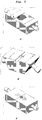
- the figure 4 represents a view of 3 possible architectures of the equipment.
- the figure 4.a represents a view where the supply (8) and discharge (10) ducts are parallel to the blade (2) while the figure 4.b illustrates a situation where the conduits arrive at an angle with respect to the blade which may be between 0 and 90 °.
- the advantage of one or other of the solutions lies in the ability to manage flow rates, dead volumes or even angles in order to avoid any problem of blockage or continuity in the flow of the fluid (4) and at the same time ensuring that a homogeneous fluid film is obtained in the open cavity (3) (circular part in the figures where the laser shots are focused).
- the figure 4.c is a variant of the previous solutions where glass coverslips have been placed at the level of the inlets (7) and outlets (9) of the fluid (4) to orient / guide its flow in the form of a homogeneous film in the cavity (3 ).
- the architectures illustrated here are not exhaustive. Indeed, the shape, the positioning and the angle of the conduits, the size and the shape of the cavity and the blade, the materials used, the shape and the positioning of the inlet (7) and outlet ports may differ. examples shown here.
- the figure 5 represents a view of 3 possible architectures of the equipment close to those presented in the figure 4 . They all have in common to present in this new configuration a groove on the upper part, the height of which corresponds to that of the cavity (3) and the positioning of which intersects the open zone of the cavity (3).
- the advantage of such an opening is to allow observation of the film by viewing means (imaging) placed perpendicular to the equipment.
- imaging placed perpendicular to the equipment.
- it is possible to follow the evolution of the film over time which makes it possible to best adapt the energy of the laser shots to the actual thickness of the film during printing or, conversely, to adapt the thickness of the film. film with the energy of the laser shot.
- the architectures illustrated here are not exhaustive.
- the shape, positioning and angle of the ducts, the size and shape of the cavity and the blade, the materials used, the shape and positioning of the inlet (7) and outlet ports, the shape , the size and positioning of the grooves may differ from the examples shown here.
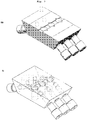
- the figure 6 presents results obtained on one of the variants of the equipment according to the invention, initially illustrated on the figure 5.e .
- a transparent view makes it possible to highlight the internal architecture of the equipment in this configuration.
- the supply and discharge ducts arrive at an angle to the cavity (3) and to the blade (2).
- the connection between the ducts and the cavity area is made by small diameter pipes to be compatible with the desired film thicknesses of less than 500 ⁇ m .
- the section of these ducts must not be too small in order to avoid any phenomenon comparable to those observed in nozzle systems (orifices) which clog easily and which bring significant mechanical stress to the cells, thus impacting their viability over time.
- the conduits will preferably have a diameter greater than 200 ⁇ m , ie at least 10 times the average size of the cells or particles that can be printed by this equipment.
- the equipment is pierced in its center by a hole (cylinder) allowing the laser to be focused in the cavity by passing through the plate (2), transparent at its wavelength.
- a zoomed view of the cavity (3) located above the blade (2) on which the fluid (4) is sent shows that the inlet (7) and outlet ports respectively (7 and 9) are formed in part by the supply and discharge ducts respectively (8 and 10) and by the glass slats placed on top of the equipment.
- the monitoring of these thicknesses correlated with the adaptation of the laser excitation parameters allows a fine adjustment of the jets generated by the absorption of the laser.
- the upper shape of the film is not necessarily flat as can be seen in the photographs. This depends on the parameters of the fluid (4) (viscosity, density, flow rate, etc.) and on the pressure / suction parameters of said fluid.
- the area of the laser shots can be spatially adapted to a part of the film where the thickness is constant. Said zone can also correspond to the whole of the cavity but in this case, the laser parameters will be adapted to the variations in thickness of the film in the targeted field.
- the characterization of the film could also be carried out by means other than the imagery cited here, one can for example think of means of spectroscopic analysis, distance measurement, shadowoscopy along a line, etc.
- the figure 9 illustrates real material jets, generated by laser without sacrificial layer.
- the 4 photographs in this figure each correspond to a specific time after the focusing of the laser shot in the ink film (4).
- the first photo was taken 5 ⁇ s after firing, the second 50 ⁇ s after and so on.
- This technique of shadow imaging is commonly called imaging resolved in time. It allows hyper-fast events to be broken down by taking photos thanks to very short lighting times.
- This series of photos illustrates the principle of laser jet generation as explained on the figure 8 former. We can see at short times the creation of a pyramidal dome surmounted by a very fine first jet then at long times we can see the rise of a much larger jet from which one or more drops stand out.
- the distance between the free surface of the film (4) and the receiving substrate on which it is desired to print it is one or more of these droplets which will be deposited.
- the distance between the ink and the printing substrate is small enough, generally less than 500 ⁇ m , that the jet directly intercepts the surface of the receiving substrate. This is referred to as a transfer regime.
- the mechanism is droplet deposition or transfer, we will speak of front laser printing.
- each printed drop appears as a small circle in the image.
- the large circle (separating the gray area from the black area) simply corresponds to the field imaged by the microscope used to take this image.
- the printed drops are typically 100 ⁇ m in diameter and are 500 ⁇ m apart from each other. This result was obtained within the equipment according to the invention in static mode (without continuous recharging).
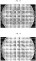
- the figure 11 presents a homogeneous result of laser printing without sacrificial layer of a colloidal ink made of water, surfactant and microbeads of 5 ⁇ m in diameter each.
- the result of the printing shows the ability of this invention to deposit droplets enclosing a small number of microbeads, on average 2 to 3 per droplet. This is proof that printing without a sacrificial layer can achieve very high resolution performance on colloidal media (which had never been demonstrated before). This result was obtained within the equipment according to the invention in static mode (without continuous recharging).
- the figure 12 presents a relatively homogeneous laser printing result without a sacrificial layer of cellular ink. This impression is a first as for the microbeads. It is very convincing and opens up very wide fields of use for this invention.
- the disparities in printing visible on the image are essentially linked to the disparities in the ink used and deposited on the slide (3) which has sedimented and aggregated in packets. Indeed, this result was obtained in static mode, that is to say without operating the equipment according to the invention in a dynamic continuous reloading mode. The aim of this result was above all to prove the ability of goldless printing to print living cells. Here again, this result was obtained within the equipment according to the invention in static mode (without continuous recharging).
- the figure 13 presents a relatively homogeneous printing result of laser printing without sacrificial layer of a homogeneous ink obtained with the equipment according to the invention working in dynamic mode, that is to say with the fluidic system working in continuous reloading.
- the figure 14 is another illustration of the ability of sacrificial layer-less printing technology to be able to be optimized as needed.
- this image we can see a field of droplets printed under the same conditions as those described so far with only one difference: the presence of an absorbing agent incorporated in the ink.
- it was melanin, a natural biological compound having a very strong absorption at the wavelength of the laser used for these experiments, namely 1030nm.
- the addition of this compound made it possible to work at lower laser energies to allow laser absorption, then the creation of the plasma and finally the hydrodynamics of the cavitation bubble. This result was obtained within the equipment according to the invention in static mode (without continuous recharging).
- the figures 15 to 17 represent views respectively in partial section, in perspective and from above of another example of a blade (2), having an optional first elevation (105), and a plate (100) in the form of a mesa, the upper surface of which is flat .
- This surface plane defines the zone of interaction (100) between the fluid and an excitation and / or observation beam, for example a laser beam.
- the blade has, on either side of this plate (100), a transverse groove (110, 120).
- Each of the grooves (110, 120) communicates through a hole (111, 121) with a conduit respectively (112, 122) vertically crossing the blade (2) and opening into the corresponding groove respectively (110, 120).
- the fluid flow occurs in a direction represented by the arrow (105) corresponding to the longitudinal direction, between a first transverse groove (110) and a second transverse groove (120).
- the first spline (110) is normally used for the fluid supply, which passes through the tray (100) before flowing into the second spline (120) where the fluid is then sucked.
- Tubes (113, 123) are respectively connected to conduits (111, 121) for the supply and / or suction of fluid carrying the transferable particles.
- One of the conduits can be connected by a multi-way valve to several inlets (114 to 116) for fluids of different types.
- Each of these channels can work either in flow (of the syringe pump type) or in pressure
- the other two edges of the plate (100), not adjacent to the grooves (110, 120) are optionally bordered by a rim (130, 140), to form a delimited area for the circulation of the fluid.
- a rim 130, 140
- the side edges exterior of the blade are delimited by flanges (150, 160).
- the flow can be controlled to ensure a homogeneous distribution of the liquid on the open part of the print head.
- a first solution consists in providing an inlet mouth as well as a rectangular outlet, the inlet and outlet ports being defined by the upper surface of the transverse grooves (110, 120) as indicated on the diagrams. figures 15 to 17 .
- the side flanges (130, 140) ensure that the shape of the liquid meniscus in the plane containing the axis (105) can be controlled. They can be physical or chemical.
- the liquid film has a perfectly flat or thinner thickness at the edges so that the flow has a higher hydrodynamic resistance at the edges.
- Another solution for alternating the nature of the fluid consists in alternating a fluid containing transferable particles, with an inert liquid.
- Another solution comprises a liquid evacuation pipe with at least two ways.
- Initialization step 1 In order to create a liquid bridge on the print head connecting the injection point and the evacuation point, a control process is put in place.
- a first solution consists in injecting liquid from the cartridges towards the head from the injection and discharge point.
- Another solution is to inject liquid from the cartridge to the head only from the injection point.
- Another solution consists in using a texture allowing total wetting of the open part of the printhead.
- a first exemplary embodiment establishes a continuous flow and controls the thickness of the film by imposing a flow rate between the point of injection and the point of discharge.
- Another exemplary embodiment establishes a continuous flow and controls the thickness of the film by imposing a pressure difference between the point of injection and the point of discharge.
- This operation is repeated cyclically.
- sensors can be integrated.
- An exemplary embodiment uses a confocal system to measure the thickness of the film.
- Another example of realization uses an optical detection system on the injection and discharge tubes.
- An advantageous development makes it possible to detect the passage of bubbles, particularly on the evacuation route.
- An advantageous development makes it possible to detect concentrations, particularly on the injection route.
Landscapes
- Health & Medical Sciences (AREA)
- Engineering & Computer Science (AREA)
- Life Sciences & Earth Sciences (AREA)
- Chemical & Material Sciences (AREA)
- Biomedical Technology (AREA)
- Zoology (AREA)
- General Health & Medical Sciences (AREA)
- Bioinformatics & Cheminformatics (AREA)
- Organic Chemistry (AREA)
- Wood Science & Technology (AREA)
- Materials Engineering (AREA)
- Genetics & Genomics (AREA)
- Manufacturing & Machinery (AREA)
- Sustainable Development (AREA)
- General Engineering & Computer Science (AREA)
- Biochemistry (AREA)
- Microbiology (AREA)
- Biotechnology (AREA)
- Molecular Biology (AREA)
- Veterinary Medicine (AREA)
- Public Health (AREA)
- Animal Behavior & Ethology (AREA)
- Oral & Maxillofacial Surgery (AREA)
- Transplantation (AREA)
- Optics & Photonics (AREA)
- Physics & Mathematics (AREA)
- Epidemiology (AREA)
- Medicinal Chemistry (AREA)
- Dermatology (AREA)
- Chemical Kinetics & Catalysis (AREA)
- Botany (AREA)
- Cell Biology (AREA)
- Cardiology (AREA)
- Heart & Thoracic Surgery (AREA)
- Vascular Medicine (AREA)
- Mechanical Engineering (AREA)
- Physical Or Chemical Processes And Apparatus (AREA)
- Apparatus Associated With Microorganisms And Enzymes (AREA)
- Application Of Or Painting With Fluid Materials (AREA)
Claims (18)
- Additivdruckeinrichtung, die ein ausrichtbares Mittel zur energetischen Erregung zum Erzeugen einer punktuellen Wechselwirkung mit einem Fluid umfasst, das einen Träger (2) überzieht, um einen in Richtung eines Ziels (11) (11) ausgerichteten Strahl zu erzeugen, wobei das Fluid aus einem flüssigen Vektor besteht, der übertragbare Inhomogenitäten enthält, dadurch gekennzeichnet, dass• das Fluid einen Flüssigkeitsfilm (4) mit einer Dicke von weniger als 500 µm bildet,• auf einem Träger (2), der wenigstens einen Bereich (3) aufweist, der eine Wechselwirkung mit dem Laser ermöglicht, in den wenigstens ein Einlass (7) mündet, wobei der Wechselwirkungsbereich (3) in wenigstens einen Auslass (9) mündet,• die Einrichtung ferner Mittel zum Zirkulieren des Fluids zwischen dem Einlass (7) und dem Auslass (9) umfasst.
- Additivdruckeinrichtung nach Anspruch 1, dadurch gekennzeichnet, dass die Dicke des Films (4) zwischen 20 und 100 µm beträgt.
- Additivdruckeinrichtung nach Anspruch 1, dadurch gekennzeichnet, dass die Dicke des Films (4) zwischen dem 3- bis 10-fachen der Nenngröße der übertragbaren Partikel beträgt.
- Additivdruckeinrichtung nach Anspruch 1, dadurch gekennzeichnet, dass die Oberfläche des Wechselwirkungsbereichs (3) größer als 0,05 mm2 ist.
- Additivdruckeinrichtung nach Anspruch 1, dadurch gekennzeichnet, dass der Einlass (7) in einen seitlichen Teil des Wechselwirkungsbereichs (3) mündet.
- Additivdruckeinrichtung nach Anspruch 1, dadurch gekennzeichnet, dass der Wechselwirkungsbereich (3) einen peripheren Teil aufweist, der seitlich in den Auslass (9) mündet.
- Additivdruckeinrichtung nach Anspruch 1, dadurch gekennzeichnet, dass der Einlass (7) und der Auslass (9) aus rohrförmigen Kanälen bestehen, die an den Anschlussbereich (3) angeschlossen sind.
- Additivdruckeinrichtung nach Anspruch 1, dadurch gekennzeichnet, dass die Fluidumwälzmittel zwischen dem Einlass (7) und dem Auslass (9) Mittel zum Steuern des Einspritzdurchsatzes (oder des auf das Fluid ausgeübten Überdrucks) und des Absaugungsdurchsatzes (oder des auf das Fluid ausgeübten Unterdrucks) enthalten, um den Fluiddurchsatz im Wechselwirkungsbereich zu regeln.
- Additivdruckeinrichtung nach dem vorhergehenden Anspruch, dadurch gekennzeichnet, dass die Mittel zur Steuerung des Einspritzdurchsatzes und den Ansaugdurchsatzes von der Messung der Dicke des Films (4) abhängen, um die Dicke des Films (4) in dem Wechselwirkungsbereich (3) zu regeln.
- Additivdruckeinrichtung nach Anspruch 1, dadurch gekennzeichnet, dass sie eine Vielzahl von Wechselwirkungsbereichen umfasst, von denen jeder einen Einlass (7) und einen Auslass (9) umfasst.
- Additivdruckeinrichtung nach Anspruch 1, dadurch gekennzeichnet, dass das Mittel zur energetischen Erregung aus einem Laser besteht.
- Additivdruckeinrichtung nach dem vorhergehenden Anspruch, dadurch gekennzeichnet, dass der Wechselwirkungsbereich in dem Wellenlängenband des Lasers und der Bildgebung transparent ist und keine Opferschicht aufweist.
- Additivdruckeinrichtung nach dem vorhergehenden Anspruch, dadurch gekennzeichnet, dass das Fluid mit einem Pigment beladen ist, das in der Emissionswellenlänge des Lasers absorbierend ist.
- Additivdruckeinrichtung nach Anspruch 11, dadurch gekennzeichnet, dass sie Bildgebungsmittel für den Wechselwirkungsbereich zum Steuern des Lasers in Abhängigkeit von der Dichte der Inhomogenitäten umfasst.
- Additivdruckeinrichtung nach Anspruch 1, dadurch gekennzeichnet, dass das Mittel zur energetischen Erregung aus einem Schallwellengenerator besteht.
- Additivdruckeinrichtung nach Anspruch 1, dadurch gekennzeichnet, dass der Träger (2) eine Platte (100) in Mesaform aufweist, deren obere Oberfläche den Wechselwirkungsbereich (100) zwischen dem Fluid und einem Erregungs- und/oder Beobachtungsstrahl definiert, wobei der Träger (2) auf beiden Seiten dieser Platte (100) eine Querrille (110, 120) aufweist, wobei jede der Rillen (110, 120) durch ein Loch (111, 121) mit jeweils einer Leitung (112, 122) kommuniziert, die vertikal durch den Träger (2) läuft und jeweils in die entsprechende Rille (110, 120) mündet.
- Additivdruckverfahren durch eine Einrichtung, die ein ausrichtbares Mittel zur energetischen Erregung zum Erzeugen einer punktuellen Wechselwirkung mit einem Fluid umfasst, das einen Träger (2) überzieht, um einen in Richtung eines Ziels (11) ausgerichteten Strahl zu erzeugen, wobei das Fluid aus einem flüssigen Vektor besteht, der übertragbare Inhomogenitäten enthält, dadurch gekennzeichnet, dass das Fluid einen Flüssigkeitsfilm (4) mit einer Dicke von weniger als 500 µm bildet, das zwischen einer Leitung des Einlasses (7) und einer Leitung des Auslasses (9) eines Trägers (2) zirkuliert, der wenigstens einen Bereich aufweist, der die Wechselwirkung mit dem Laser ermöglicht und in den wenigstens ein Einlass (7) mündet.
- Additivdruckverfahren nach dem vorhergehenden Anspruch, dadurch gekennzeichnet, dass das Energieniveau pro Impuls durch einen Rechner in Abhängigkeit von dem Ergebnis der Messung von Eigenschaften des in dem Wechselwirkungsbereich vorhandenen Fluids vorgegeben wird, wobei die Messungen die Partikeldichte und/oder die Viskosität und/oder die Dicke des Films (4) enthalten.
Applications Claiming Priority (2)
| Application Number | Priority Date | Filing Date | Title |
|---|---|---|---|
| FR1752131A FR3063931B1 (fr) | 2017-03-15 | 2017-03-15 | Equipement et procede d'impression additive |
| PCT/FR2018/050536 WO2018167402A1 (fr) | 2017-03-15 | 2018-03-08 | Equipement et procede d'impression additive |
Publications (2)
| Publication Number | Publication Date |
|---|---|
| EP3595592A1 EP3595592A1 (de) | 2020-01-22 |
| EP3595592B1 true EP3595592B1 (de) | 2021-11-03 |
Family
ID=59520986
Family Applications (1)
| Application Number | Title | Priority Date | Filing Date |
|---|---|---|---|
| EP18712977.0A Active EP3595592B1 (de) | 2017-03-15 | 2018-03-08 | Vorrichtung und verfahren zur generativen fertigung |
Country Status (8)
| Country | Link |
|---|---|
| US (1) | US20200102529A1 (de) |
| EP (1) | EP3595592B1 (de) |
| JP (1) | JP7170674B2 (de) |
| KR (1) | KR102495038B1 (de) |
| CN (1) | CN110402125B (de) |
| ES (1) | ES2905587T3 (de) |
| FR (1) | FR3063931B1 (de) |
| WO (1) | WO2018167402A1 (de) |
Families Citing this family (12)
| Publication number | Priority date | Publication date | Assignee | Title |
|---|---|---|---|---|
| FR3093944B1 (fr) | 2019-03-22 | 2021-03-19 | Poietis | Cartouche pour bioimpression |
| DE102019115780B4 (de) * | 2019-06-11 | 2021-10-21 | Technische Universität Dresden | Verfahren und Vorrichtungen zum Mehrphotonendruck und zur Inspektion dreidimensionaler Strukturen |
| US11440241B2 (en) * | 2019-06-14 | 2022-09-13 | Io Tech Group Ltd. | Additive manufacturing of a free form object made of multicomponent materials |
| US12427229B2 (en) | 2020-08-06 | 2025-09-30 | PhosPrint P.C. | Laser ablation/removal and laser induced forward transfer of biological material |
| CN113085185A (zh) * | 2021-04-08 | 2021-07-09 | 北京理工大学 | 基于时域整形飞秒激光诱导液体薄膜前向转移的方法 |
| FR3124523B1 (fr) | 2021-06-25 | 2024-11-29 | Poietis | Equipement d’impression additive par laser mid ir |
| US12420479B2 (en) * | 2021-12-23 | 2025-09-23 | Reophotonics, Ltd. | Systems for printing viscous materials using laser assisted deposition |
| WO2023247801A1 (en) | 2022-06-24 | 2023-12-28 | Katholieke Universiteit Leuven | Printing of cell aggregates |
| FR3141092B1 (fr) * | 2022-10-20 | 2025-11-21 | Poietis | Manipulation et transfert d’objets par propulsion |
| CN116833423B (zh) * | 2023-05-12 | 2025-08-01 | 中国石油大学(华东) | 一种双脉冲激光驱动的液态金属无喷孔喷射方法 |
| US12466132B2 (en) * | 2023-11-28 | 2025-11-11 | Nissan North America, Inc. | Replenishment system for three-dimensional printing system |
| CN119972210B (zh) * | 2025-02-18 | 2025-10-24 | 天府绛溪实验室 | 一种激光驱动液体环流并探测声信号的设备及方法 |
Family Cites Families (20)
| Publication number | Priority date | Publication date | Assignee | Title |
|---|---|---|---|---|
| US6561643B1 (en) * | 1997-06-30 | 2003-05-13 | Hewlett-Packard Co. | Advanced media determination system for inkjet printing |
| US7717544B2 (en) * | 2004-10-01 | 2010-05-18 | Labcyte Inc. | Method for acoustically ejecting a droplet of fluid from a reservoir by an acoustic fluid ejection apparatus |
| CA2571859A1 (en) * | 2004-07-06 | 2006-02-09 | University Of Utah Research Foundation | Spotting device and method for high concentration spot deposition on microarrays and other microscale devices |
| PH12011501221A1 (en) * | 2008-12-17 | 2010-06-24 | Basf Se | Method and printing press for printing a substrate |
| CN102326077A (zh) * | 2009-02-18 | 2012-01-18 | 索尼公司 | 印刷生物活性材料 |
| KR20100107634A (ko) * | 2009-03-26 | 2010-10-06 | 삼성전자주식회사 | 바이오칩의 제조방법 |
| DE102009059042A1 (de) * | 2009-12-10 | 2011-06-16 | Schmid Technology Gmbh | Verfahren und Vorrichtung zur Übertragung von Drucksubstanz von einem Drucksubstanzträger auf ein Substrat |
| ES2671594T3 (es) | 2010-03-04 | 2018-06-07 | INSERM (Institut National de la Santé et de la Recherche Médicale) | Puesto de bioimpresión, ensamblaje que comprende dicho puesto de bioimpresión y método de bioimpresión |
| CN102765257B (zh) * | 2012-08-10 | 2015-02-25 | 李支斌 | 打印机墨水管路恒压缓冲分配器 |
| KR20140051042A (ko) * | 2012-10-21 | 2014-04-30 | 포톤 젯 리미티드 | 다중기술 인쇄 시스템 |
| WO2014061024A1 (en) | 2012-10-21 | 2014-04-24 | Photon Jet Ltd | A multi-technology printing system |
| JP6432331B2 (ja) * | 2014-12-15 | 2018-12-05 | 富士ゼロックス株式会社 | 乾燥装置、画像形成装置、及び乾燥プログラム |
| FR3030361B1 (fr) * | 2014-12-17 | 2017-01-20 | Univ Bordeaux | Procede d'impression d'elements biologiques par laser et dispositif pour sa mise en oeuvre |
| FR3030360B1 (fr) * | 2014-12-17 | 2018-07-13 | Universite de Bordeaux | Procede d'impression par laser et dispositif pour sa mise en oeuvre |
| AU2016297675B2 (en) * | 2015-07-22 | 2020-07-02 | Inventia Life Science Pty Ltd | Process for printing 3D tissue culture models |
| CN205818681U (zh) * | 2016-02-26 | 2016-12-21 | 多佛欧洲有限责任公司 | 用于连续喷墨打印机的油墨回路的单件可拆装组件 |
| CN106046940A (zh) * | 2016-07-19 | 2016-10-26 | 青岛良友科技发展有限公司 | 用于普通印刷介质及墙纸原纸的环保型喷墨打印墨水组合物、其制备方法及其应用 |
| WO2019207408A1 (en) * | 2018-04-23 | 2019-10-31 | Io Tech Group, Ltd. | Laser-based droplet array jetting of high viscous materials |
| US20200298440A1 (en) * | 2019-03-20 | 2020-09-24 | Jun Aoto | Method for forming flying object using optical vortex laser, and image forming method and apparatus |
| JP7287124B2 (ja) * | 2019-06-03 | 2023-06-06 | 株式会社リコー | 光吸収材を飛翔させる装置、立体造形物を造形する装置、光吸収材を飛翔させる方法 |
-
2017
- 2017-03-15 FR FR1752131A patent/FR3063931B1/fr active Active
-
2018
- 2018-03-08 JP JP2019571801A patent/JP7170674B2/ja active Active
- 2018-03-08 EP EP18712977.0A patent/EP3595592B1/de active Active
- 2018-03-08 CN CN201880017567.6A patent/CN110402125B/zh active Active
- 2018-03-08 US US16/494,737 patent/US20200102529A1/en active Pending
- 2018-03-08 WO PCT/FR2018/050536 patent/WO2018167402A1/fr not_active Ceased
- 2018-03-08 KR KR1020197030353A patent/KR102495038B1/ko active Active
- 2018-03-08 ES ES18712977T patent/ES2905587T3/es active Active
Non-Patent Citations (1)
| Title |
|---|
| None * |
Also Published As
| Publication number | Publication date |
|---|---|
| JP2020513850A (ja) | 2020-05-21 |
| EP3595592A1 (de) | 2020-01-22 |
| FR3063931B1 (fr) | 2019-03-22 |
| CN110402125B (zh) | 2022-05-27 |
| US20200102529A1 (en) | 2020-04-02 |
| KR102495038B1 (ko) | 2023-02-06 |
| FR3063931A1 (fr) | 2018-09-21 |
| CN110402125A (zh) | 2019-11-01 |
| ES2905587T3 (es) | 2022-04-11 |
| KR20190126884A (ko) | 2019-11-12 |
| JP7170674B2 (ja) | 2022-11-14 |
| WO2018167402A1 (fr) | 2018-09-20 |
Similar Documents
| Publication | Publication Date | Title |
|---|---|---|
| EP3595592A1 (de) | Vorrichtung und verfahren zur generativen fertigung | |
| EP3234102B1 (de) | Verfahren zum laserdrucken von biologischen komponenten und vorrichtung zur implementierung des besagten verfahrens | |
| EP3233499B1 (de) | Laserdruckverfahren und vorrichtung zur umsetzung dieses verfahrens | |
| TWI764911B (zh) | 用於材料處理之雷射引發施配系統、用於材料處理印表機之纖維束及將施體材料施配於接收器基板上之方法 | |
| FR3093944A1 (fr) | Cartouche pour bioimpression | |
| FR2933713A1 (fr) | Procede et dispositif de manipulation et d'observation de gouttes de liquide | |
| WO2012120424A1 (fr) | Systeme microfluidique pour controler un profil de concentration de molecules susceptibles de stimuler une cible | |
| EP4149739A1 (de) | Verfahren zur generativen fertigung in einem einstellbaren eingeschränkten medium | |
| FR3102377A1 (fr) | Equipement et procédé de dépôt par projection de particules par ondes de choc laser | |
| FR3022807A1 (fr) | Dispositif de nebulisation de differents types de liquide | |
| EP3393820B1 (de) | Verfahren zur herstellung von durch änderung des betrachtungswinkels selektiv betrachtbaren bildern mittels ätzen durch ein linsenförmiges gitter | |
| EP3628034B1 (de) | System zum abscheiden von material und zugehöriges verfahren | |
| WO2022269187A1 (fr) | Equipement d'impression additive par laser mid ir | |
| WO2024084030A1 (fr) | Manipulation et transfert d'objets par propulsion | |
| WO2023232813A1 (fr) | Dispositif microfluidique, système et procédé de manipulation d'un fluide en écoulement | |
| FR3141091A1 (fr) | Impression d’objets a partir d’un puits |
Legal Events
| Date | Code | Title | Description |
|---|---|---|---|
| STAA | Information on the status of an ep patent application or granted ep patent |
Free format text: STATUS: UNKNOWN |
|
| STAA | Information on the status of an ep patent application or granted ep patent |
Free format text: STATUS: THE INTERNATIONAL PUBLICATION HAS BEEN MADE |
|
| PUAI | Public reference made under article 153(3) epc to a published international application that has entered the european phase |
Free format text: ORIGINAL CODE: 0009012 |
|
| STAA | Information on the status of an ep patent application or granted ep patent |
Free format text: STATUS: REQUEST FOR EXAMINATION WAS MADE |
|
| 17P | Request for examination filed |
Effective date: 20191007 |
|
| AK | Designated contracting states |
Kind code of ref document: A1 Designated state(s): AL AT BE BG CH CY CZ DE DK EE ES FI FR GB GR HR HU IE IS IT LI LT LU LV MC MK MT NL NO PL PT RO RS SE SI SK SM TR |
|
| AX | Request for extension of the european patent |
Extension state: BA ME |
|
| DAV | Request for validation of the european patent (deleted) | ||
| DAX | Request for extension of the european patent (deleted) | ||
| STAA | Information on the status of an ep patent application or granted ep patent |
Free format text: STATUS: EXAMINATION IS IN PROGRESS |
|
| 17Q | First examination report despatched |
Effective date: 20201013 |
|
| GRAP | Despatch of communication of intention to grant a patent |
Free format text: ORIGINAL CODE: EPIDOSNIGR1 |
|
| STAA | Information on the status of an ep patent application or granted ep patent |
Free format text: STATUS: GRANT OF PATENT IS INTENDED |
|
| INTG | Intention to grant announced |
Effective date: 20210709 |
|
| GRAS | Grant fee paid |
Free format text: ORIGINAL CODE: EPIDOSNIGR3 |
|
| GRAA | (expected) grant |
Free format text: ORIGINAL CODE: 0009210 |
|
| STAA | Information on the status of an ep patent application or granted ep patent |
Free format text: STATUS: THE PATENT HAS BEEN GRANTED |
|
| AK | Designated contracting states |
Kind code of ref document: B1 Designated state(s): AL AT BE BG CH CY CZ DE DK EE ES FI FR GB GR HR HU IE IS IT LI LT LU LV MC MK MT NL NO PL PT RO RS SE SI SK SM TR |
|
| REG | Reference to a national code |
Ref country code: GB Ref legal event code: FG4D Free format text: NOT ENGLISH |
|
| REG | Reference to a national code |
Ref country code: AT Ref legal event code: REF Ref document number: 1443320 Country of ref document: AT Kind code of ref document: T Effective date: 20211115 Ref country code: CH Ref legal event code: EP |
|
| REG | Reference to a national code |
Ref country code: IE Ref legal event code: FG4D Free format text: LANGUAGE OF EP DOCUMENT: FRENCH |
|
| REG | Reference to a national code |
Ref country code: DE Ref legal event code: R096 Ref document number: 602018026064 Country of ref document: DE |
|
| REG | Reference to a national code |
Ref country code: SE Ref legal event code: TRGR |
|
| REG | Reference to a national code |
Ref country code: NL Ref legal event code: FP |
|
| REG | Reference to a national code |
Ref country code: LT Ref legal event code: MG9D |
|
| REG | Reference to a national code |
Ref country code: AT Ref legal event code: MK05 Ref document number: 1443320 Country of ref document: AT Kind code of ref document: T Effective date: 20211103 |
|
| REG | Reference to a national code |
Ref country code: ES Ref legal event code: FG2A Ref document number: 2905587 Country of ref document: ES Kind code of ref document: T3 Effective date: 20220411 |
|
| PG25 | Lapsed in a contracting state [announced via postgrant information from national office to epo] |
Ref country code: RS Free format text: LAPSE BECAUSE OF FAILURE TO SUBMIT A TRANSLATION OF THE DESCRIPTION OR TO PAY THE FEE WITHIN THE PRESCRIBED TIME-LIMIT Effective date: 20211103 Ref country code: LT Free format text: LAPSE BECAUSE OF FAILURE TO SUBMIT A TRANSLATION OF THE DESCRIPTION OR TO PAY THE FEE WITHIN THE PRESCRIBED TIME-LIMIT Effective date: 20211103 Ref country code: FI Free format text: LAPSE BECAUSE OF FAILURE TO SUBMIT A TRANSLATION OF THE DESCRIPTION OR TO PAY THE FEE WITHIN THE PRESCRIBED TIME-LIMIT Effective date: 20211103 Ref country code: BG Free format text: LAPSE BECAUSE OF FAILURE TO SUBMIT A TRANSLATION OF THE DESCRIPTION OR TO PAY THE FEE WITHIN THE PRESCRIBED TIME-LIMIT Effective date: 20220203 Ref country code: AT Free format text: LAPSE BECAUSE OF FAILURE TO SUBMIT A TRANSLATION OF THE DESCRIPTION OR TO PAY THE FEE WITHIN THE PRESCRIBED TIME-LIMIT Effective date: 20211103 |
|
| PG25 | Lapsed in a contracting state [announced via postgrant information from national office to epo] |
Ref country code: IS Free format text: LAPSE BECAUSE OF FAILURE TO SUBMIT A TRANSLATION OF THE DESCRIPTION OR TO PAY THE FEE WITHIN THE PRESCRIBED TIME-LIMIT Effective date: 20220303 Ref country code: PT Free format text: LAPSE BECAUSE OF FAILURE TO SUBMIT A TRANSLATION OF THE DESCRIPTION OR TO PAY THE FEE WITHIN THE PRESCRIBED TIME-LIMIT Effective date: 20220303 Ref country code: PL Free format text: LAPSE BECAUSE OF FAILURE TO SUBMIT A TRANSLATION OF THE DESCRIPTION OR TO PAY THE FEE WITHIN THE PRESCRIBED TIME-LIMIT Effective date: 20211103 Ref country code: NO Free format text: LAPSE BECAUSE OF FAILURE TO SUBMIT A TRANSLATION OF THE DESCRIPTION OR TO PAY THE FEE WITHIN THE PRESCRIBED TIME-LIMIT Effective date: 20220203 Ref country code: LV Free format text: LAPSE BECAUSE OF FAILURE TO SUBMIT A TRANSLATION OF THE DESCRIPTION OR TO PAY THE FEE WITHIN THE PRESCRIBED TIME-LIMIT Effective date: 20211103 Ref country code: HR Free format text: LAPSE BECAUSE OF FAILURE TO SUBMIT A TRANSLATION OF THE DESCRIPTION OR TO PAY THE FEE WITHIN THE PRESCRIBED TIME-LIMIT Effective date: 20211103 Ref country code: GR Free format text: LAPSE BECAUSE OF FAILURE TO SUBMIT A TRANSLATION OF THE DESCRIPTION OR TO PAY THE FEE WITHIN THE PRESCRIBED TIME-LIMIT Effective date: 20220204 |
|
| PG25 | Lapsed in a contracting state [announced via postgrant information from national office to epo] |
Ref country code: SM Free format text: LAPSE BECAUSE OF FAILURE TO SUBMIT A TRANSLATION OF THE DESCRIPTION OR TO PAY THE FEE WITHIN THE PRESCRIBED TIME-LIMIT Effective date: 20211103 Ref country code: SK Free format text: LAPSE BECAUSE OF FAILURE TO SUBMIT A TRANSLATION OF THE DESCRIPTION OR TO PAY THE FEE WITHIN THE PRESCRIBED TIME-LIMIT Effective date: 20211103 Ref country code: RO Free format text: LAPSE BECAUSE OF FAILURE TO SUBMIT A TRANSLATION OF THE DESCRIPTION OR TO PAY THE FEE WITHIN THE PRESCRIBED TIME-LIMIT Effective date: 20211103 Ref country code: EE Free format text: LAPSE BECAUSE OF FAILURE TO SUBMIT A TRANSLATION OF THE DESCRIPTION OR TO PAY THE FEE WITHIN THE PRESCRIBED TIME-LIMIT Effective date: 20211103 Ref country code: DK Free format text: LAPSE BECAUSE OF FAILURE TO SUBMIT A TRANSLATION OF THE DESCRIPTION OR TO PAY THE FEE WITHIN THE PRESCRIBED TIME-LIMIT Effective date: 20211103 Ref country code: CZ Free format text: LAPSE BECAUSE OF FAILURE TO SUBMIT A TRANSLATION OF THE DESCRIPTION OR TO PAY THE FEE WITHIN THE PRESCRIBED TIME-LIMIT Effective date: 20211103 |
|
| REG | Reference to a national code |
Ref country code: DE Ref legal event code: R097 Ref document number: 602018026064 Country of ref document: DE |
|
| PLBE | No opposition filed within time limit |
Free format text: ORIGINAL CODE: 0009261 |
|
| STAA | Information on the status of an ep patent application or granted ep patent |
Free format text: STATUS: NO OPPOSITION FILED WITHIN TIME LIMIT |
|
| 26N | No opposition filed |
Effective date: 20220804 |
|
| PG25 | Lapsed in a contracting state [announced via postgrant information from national office to epo] |
Ref country code: MC Free format text: LAPSE BECAUSE OF FAILURE TO SUBMIT A TRANSLATION OF THE DESCRIPTION OR TO PAY THE FEE WITHIN THE PRESCRIBED TIME-LIMIT Effective date: 20211103 Ref country code: AL Free format text: LAPSE BECAUSE OF FAILURE TO SUBMIT A TRANSLATION OF THE DESCRIPTION OR TO PAY THE FEE WITHIN THE PRESCRIBED TIME-LIMIT Effective date: 20211103 |
|
| GBPC | Gb: european patent ceased through non-payment of renewal fee |
Effective date: 20220308 |
|
| PG25 | Lapsed in a contracting state [announced via postgrant information from national office to epo] |
Ref country code: SI Free format text: LAPSE BECAUSE OF FAILURE TO SUBMIT A TRANSLATION OF THE DESCRIPTION OR TO PAY THE FEE WITHIN THE PRESCRIBED TIME-LIMIT Effective date: 20211103 |
|
| PG25 | Lapsed in a contracting state [announced via postgrant information from national office to epo] |
Ref country code: LU Free format text: LAPSE BECAUSE OF NON-PAYMENT OF DUE FEES Effective date: 20220308 Ref country code: IE Free format text: LAPSE BECAUSE OF NON-PAYMENT OF DUE FEES Effective date: 20220308 Ref country code: GB Free format text: LAPSE BECAUSE OF NON-PAYMENT OF DUE FEES Effective date: 20220308 |
|
| PG25 | Lapsed in a contracting state [announced via postgrant information from national office to epo] |
Ref country code: MK Free format text: LAPSE BECAUSE OF FAILURE TO SUBMIT A TRANSLATION OF THE DESCRIPTION OR TO PAY THE FEE WITHIN THE PRESCRIBED TIME-LIMIT Effective date: 20211103 Ref country code: CY Free format text: LAPSE BECAUSE OF FAILURE TO SUBMIT A TRANSLATION OF THE DESCRIPTION OR TO PAY THE FEE WITHIN THE PRESCRIBED TIME-LIMIT Effective date: 20211103 |
|
| PG25 | Lapsed in a contracting state [announced via postgrant information from national office to epo] |
Ref country code: HU Free format text: LAPSE BECAUSE OF FAILURE TO SUBMIT A TRANSLATION OF THE DESCRIPTION OR TO PAY THE FEE WITHIN THE PRESCRIBED TIME-LIMIT; INVALID AB INITIO Effective date: 20180308 |
|
| PG25 | Lapsed in a contracting state [announced via postgrant information from national office to epo] |
Ref country code: MT Free format text: LAPSE BECAUSE OF FAILURE TO SUBMIT A TRANSLATION OF THE DESCRIPTION OR TO PAY THE FEE WITHIN THE PRESCRIBED TIME-LIMIT Effective date: 20211103 |
|
| PGFP | Annual fee paid to national office [announced via postgrant information from national office to epo] |
Ref country code: ES Payment date: 20250429 Year of fee payment: 8 |
|
| PGFP | Annual fee paid to national office [announced via postgrant information from national office to epo] |
Ref country code: IT Payment date: 20250331 Year of fee payment: 8 |
|
| PGFP | Annual fee paid to national office [announced via postgrant information from national office to epo] |
Ref country code: CH Payment date: 20250403 Year of fee payment: 8 |
|
| PGFP | Annual fee paid to national office [announced via postgrant information from national office to epo] |
Ref country code: TR Payment date: 20250407 Year of fee payment: 8 |
|
| REG | Reference to a national code |
Ref country code: CH Ref legal event code: U11 Free format text: ST27 STATUS EVENT CODE: U-0-0-U10-U11 (AS PROVIDED BY THE NATIONAL OFFICE) Effective date: 20260401 |
|
| PGFP | Annual fee paid to national office [announced via postgrant information from national office to epo] |
Ref country code: SE Payment date: 20260331 Year of fee payment: 9 |
|
| PGFP | Annual fee paid to national office [announced via postgrant information from national office to epo] |
Ref country code: DE Payment date: 20260331 Year of fee payment: 9 |
|
| PGFP | Annual fee paid to national office [announced via postgrant information from national office to epo] |
Ref country code: BE Payment date: 20260331 Year of fee payment: 9 |
|
| PGFP | Annual fee paid to national office [announced via postgrant information from national office to epo] |
Ref country code: NL Payment date: 20260331 Year of fee payment: 9 |
|
| PGFP | Annual fee paid to national office [announced via postgrant information from national office to epo] |
Ref country code: FR Payment date: 20260331 Year of fee payment: 9 |