EP3595273B1 - Faltbare elektronische vorrichtung und verfahren zur steuerung einer faltbaren elektronischen vorrichtung - Google Patents
Faltbare elektronische vorrichtung und verfahren zur steuerung einer faltbaren elektronischen vorrichtung Download PDFInfo
- Publication number
- EP3595273B1 EP3595273B1 EP19183892.9A EP19183892A EP3595273B1 EP 3595273 B1 EP3595273 B1 EP 3595273B1 EP 19183892 A EP19183892 A EP 19183892A EP 3595273 B1 EP3595273 B1 EP 3595273B1
- Authority
- EP
- European Patent Office
- Prior art keywords
- electronic apparatus
- foldable electronic
- acoustic opening
- acoustic
- connection end
- Prior art date
- Legal status (The legal status is an assumption and is not a legal conclusion. Google has not performed a legal analysis and makes no representation as to the accuracy of the status listed.)
- Active
Links
Images


Classifications
-
- H—ELECTRICITY
- H04—ELECTRIC COMMUNICATION TECHNIQUE
- H04M—TELEPHONIC COMMUNICATION
- H04M1/00—Substation equipment, e.g. for use by subscribers
- H04M1/02—Constructional features of telephone sets
- H04M1/0202—Portable telephone sets, e.g. cordless phones, mobile phones or bar type handsets
- H04M1/0206—Portable telephones comprising a plurality of mechanically joined movable body parts, e.g. hinged housings
- H04M1/0241—Portable telephones comprising a plurality of mechanically joined movable body parts, e.g. hinged housings using relative motion of the body parts to change the operational status of the telephone set, e.g. switching on/off, answering incoming call
- H04M1/0243—Portable telephones comprising a plurality of mechanically joined movable body parts, e.g. hinged housings using relative motion of the body parts to change the operational status of the telephone set, e.g. switching on/off, answering incoming call using the relative angle between housings
-
- F—MECHANICAL ENGINEERING; LIGHTING; HEATING; WEAPONS; BLASTING
- F16—ENGINEERING ELEMENTS AND UNITS; GENERAL MEASURES FOR PRODUCING AND MAINTAINING EFFECTIVE FUNCTIONING OF MACHINES OR INSTALLATIONS; THERMAL INSULATION IN GENERAL
- F16C—SHAFTS; FLEXIBLE SHAFTS; ELEMENTS OR CRANKSHAFT MECHANISMS; ROTARY BODIES OTHER THAN GEARING ELEMENTS; BEARINGS
- F16C11/00—Pivots; Pivotal connections
- F16C11/04—Pivotal connections
-
- H—ELECTRICITY
- H04—ELECTRIC COMMUNICATION TECHNIQUE
- H04M—TELEPHONIC COMMUNICATION
- H04M1/00—Substation equipment, e.g. for use by subscribers
- H04M1/02—Constructional features of telephone sets
- H04M1/0202—Portable telephone sets, e.g. cordless phones, mobile phones or bar type handsets
- H04M1/0206—Portable telephones comprising a plurality of mechanically joined movable body parts, e.g. hinged housings
- H04M1/0208—Portable telephones comprising a plurality of mechanically joined movable body parts, e.g. hinged housings characterized by the relative motions of the body parts
- H04M1/0214—Foldable telephones, i.e. with body parts pivoting to an open position around an axis parallel to the plane they define in closed position
-
- G—PHYSICS
- G06—COMPUTING OR CALCULATING; COUNTING
- G06F—ELECTRIC DIGITAL DATA PROCESSING
- G06F1/00—Details not covered by groups G06F3/00 - G06F13/00 and G06F21/00
- G06F1/16—Constructional details or arrangements
- G06F1/1613—Constructional details or arrangements for portable computers
- G06F1/1615—Constructional details or arrangements for portable computers with several enclosures having relative motions, each enclosure supporting at least one I/O or computing function
- G06F1/1616—Constructional details or arrangements for portable computers with several enclosures having relative motions, each enclosure supporting at least one I/O or computing function with folding flat displays, e.g. laptop computers or notebooks having a clamshell configuration, with body parts pivoting to an open position around an axis parallel to the plane they define in closed position
-
- G—PHYSICS
- G06—COMPUTING OR CALCULATING; COUNTING
- G06F—ELECTRIC DIGITAL DATA PROCESSING
- G06F1/00—Details not covered by groups G06F3/00 - G06F13/00 and G06F21/00
- G06F1/16—Constructional details or arrangements
- G06F1/1613—Constructional details or arrangements for portable computers
- G06F1/1633—Constructional details or arrangements of portable computers not specific to the type of enclosures covered by groups G06F1/1615 - G06F1/1626
- G06F1/1637—Details related to the display arrangement, including those related to the mounting of the display in the housing
- G06F1/1652—Details related to the display arrangement, including those related to the mounting of the display in the housing the display being flexible, e.g. mimicking a sheet of paper, or rollable
-
- G—PHYSICS
- G06—COMPUTING OR CALCULATING; COUNTING
- G06F—ELECTRIC DIGITAL DATA PROCESSING
- G06F1/00—Details not covered by groups G06F3/00 - G06F13/00 and G06F21/00
- G06F1/16—Constructional details or arrangements
- G06F1/1613—Constructional details or arrangements for portable computers
- G06F1/1633—Constructional details or arrangements of portable computers not specific to the type of enclosures covered by groups G06F1/1615 - G06F1/1626
- G06F1/1656—Details related to functional adaptations of the enclosure, e.g. to provide protection against EMI, shock, water, or to host detachable peripherals like a mouse or removable expansions units like PCMCIA cards, or to provide access to internal components for maintenance or to removable storage supports like CDs or DVDs, or to mechanically mount accessories
-
- G—PHYSICS
- G06—COMPUTING OR CALCULATING; COUNTING
- G06F—ELECTRIC DIGITAL DATA PROCESSING
- G06F1/00—Details not covered by groups G06F3/00 - G06F13/00 and G06F21/00
- G06F1/16—Constructional details or arrangements
- G06F1/1613—Constructional details or arrangements for portable computers
- G06F1/1633—Constructional details or arrangements of portable computers not specific to the type of enclosures covered by groups G06F1/1615 - G06F1/1626
- G06F1/1675—Miscellaneous details related to the relative movement between the different enclosures or enclosure parts
- G06F1/1681—Details related solely to hinges
-
- G—PHYSICS
- G06—COMPUTING OR CALCULATING; COUNTING
- G06F—ELECTRIC DIGITAL DATA PROCESSING
- G06F1/00—Details not covered by groups G06F3/00 - G06F13/00 and G06F21/00
- G06F1/16—Constructional details or arrangements
- G06F1/1613—Constructional details or arrangements for portable computers
- G06F1/1633—Constructional details or arrangements of portable computers not specific to the type of enclosures covered by groups G06F1/1615 - G06F1/1626
- G06F1/1684—Constructional details or arrangements related to integrated I/O peripherals not covered by groups G06F1/1635 - G06F1/1675
- G06F1/1688—Constructional details or arrangements related to integrated I/O peripherals not covered by groups G06F1/1635 - G06F1/1675 the I/O peripheral being integrated loudspeakers
-
- H—ELECTRICITY
- H04—ELECTRIC COMMUNICATION TECHNIQUE
- H04M—TELEPHONIC COMMUNICATION
- H04M1/00—Substation equipment, e.g. for use by subscribers
- H04M1/02—Constructional features of telephone sets
- H04M1/0202—Portable telephone sets, e.g. cordless phones, mobile phones or bar type handsets
- H04M1/0206—Portable telephones comprising a plurality of mechanically joined movable body parts, e.g. hinged housings
- H04M1/0208—Portable telephones comprising a plurality of mechanically joined movable body parts, e.g. hinged housings characterized by the relative motions of the body parts
- H04M1/0214—Foldable telephones, i.e. with body parts pivoting to an open position around an axis parallel to the plane they define in closed position
- H04M1/0216—Foldable in one direction, i.e. using a one degree of freedom hinge
-
- H—ELECTRICITY
- H04—ELECTRIC COMMUNICATION TECHNIQUE
- H04M—TELEPHONIC COMMUNICATION
- H04M1/00—Substation equipment, e.g. for use by subscribers
- H04M1/02—Constructional features of telephone sets
- H04M1/0202—Portable telephone sets, e.g. cordless phones, mobile phones or bar type handsets
- H04M1/026—Details of the structure or mounting of specific components
- H04M1/0266—Details of the structure or mounting of specific components for a display module assembly
- H04M1/0268—Details of the structure or mounting of specific components for a display module assembly including a flexible display panel
-
- H—ELECTRICITY
- H04—ELECTRIC COMMUNICATION TECHNIQUE
- H04M—TELEPHONIC COMMUNICATION
- H04M1/00—Substation equipment, e.g. for use by subscribers
- H04M1/02—Constructional features of telephone sets
- H04M1/03—Constructional features of telephone transmitters or receivers, e.g. telephone hand-sets
-
- H—ELECTRICITY
- H04—ELECTRIC COMMUNICATION TECHNIQUE
- H04M—TELEPHONIC COMMUNICATION
- H04M1/00—Substation equipment, e.g. for use by subscribers
- H04M1/72—Mobile telephones; Cordless telephones, i.e. devices for establishing wireless links to base stations without route selection
- H04M1/724—User interfaces specially adapted for cordless or mobile telephones
- H04M1/72448—User interfaces specially adapted for cordless or mobile telephones with means for adapting the functionality of the device according to specific conditions
- H04M1/72454—User interfaces specially adapted for cordless or mobile telephones with means for adapting the functionality of the device according to specific conditions according to context-related or environment-related conditions
-
- H—ELECTRICITY
- H04—ELECTRIC COMMUNICATION TECHNIQUE
- H04R—LOUDSPEAKERS, MICROPHONES, GRAMOPHONE PICK-UPS OR LIKE ACOUSTIC ELECTROMECHANICAL TRANSDUCERS; ELECTRIC HEARING AIDS; PUBLIC ADDRESS SYSTEMS
- H04R1/00—Details of transducers, loudspeakers or microphones
- H04R1/02—Casings; Cabinets ; Supports therefor; Mountings therein
- H04R1/028—Casings; Cabinets ; Supports therefor; Mountings therein associated with devices performing functions other than acoustics, e.g. electric candles
-
- H—ELECTRICITY
- H04—ELECTRIC COMMUNICATION TECHNIQUE
- H04R—LOUDSPEAKERS, MICROPHONES, GRAMOPHONE PICK-UPS OR LIKE ACOUSTIC ELECTROMECHANICAL TRANSDUCERS; ELECTRIC HEARING AIDS; PUBLIC ADDRESS SYSTEMS
- H04R2499/00—Aspects covered by H04R or H04S not otherwise provided for in their subgroups
- H04R2499/10—General applications
- H04R2499/15—Transducers incorporated in visual displaying devices, e.g. televisions, computer displays, laptops
Definitions
- the present disclosure relates to the field of electronic apparatus technologies, and more particularly to a foldable electronic apparatus and a method for controlling the foldable electronic apparatus.
- Related technologies are known from KR 2017 0086321 A1 and US 2007/087793 A1 .
- electronic apparatuses may only be held in specific manners to make and answer calls for their relatively simple receiving structures.
- existing receiving structures may not meet call requirements of folded electronic apparatuses in diversified application scenarios.
- the first acoustic opening is defined in the side of the first body opposite the inner folding surface and the second acoustic opening is defined in the side of the foldable electronic apparatus where the inner folding surface is located, which allows the foldable electronic apparatus to selectively emit sounds through the first acoustic opening or the second acoustic opening when making and answering calls according to the states between the first body and the second body, thereby meeting call requirements of the foldable electronic apparatus in different application scenarios and improving the user experience.
- orientation or positional relationship term mentioned in the present disclosure such as “top”, “bottom”, “up”, “down”, “front”, “rear”, “left”, “right”, “inside”, “outside”, “side”, or the like is based on the orientation or positional relationship illustrated in the drawings, and is merely for convenience of description and simplified description, rather than implied or indicating that the device or component referred to must have a particular orientation, a structure and operated in a particular orientation, and thus is not to be construed as limiting the present disclosure.
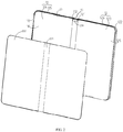
- the foldable electronic apparatus 100 includes a casing assembly 10 and a flexible display assembly 20 disposed at the casing assembly 10.
- the casing assembly 10 includes a first body 11, a second body 12, and a bendable body 13 rotatably connected between the first body 11 and the second body 12.
- the first body 11 may be rotatable relative to the second body 12 via the bendable body 30 to switch the foldable electronic apparatus 100 between a folded state and an un folded state. In the folded state, the first body 11 and the second body 12 overlap with each other. In the folded state, the first body 11 is unfolded relative to the second body 12.
- the first body 11 includes a first surface 11a and a second surface 11b opposite the first surface 11a.
- the second body 12 includes a first surface 12a and a second surface 12b opposite the first surface 12a.
- the foldable electronic apparatus 100 includes a first surface 100a and a second surface 100b opposite the first surface 100a.
- the first surface 11a of the first body 11 and the first surface 12a of the second body 12 are located at the first surface 100a of the foldable electronic apparatus 100.
- the second surface 11b of the first body 11 and the second surface 12b of the second body 12 are located at the second surface 100b of the foldable electronic apparatus 100.
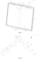
- the flexible display screen assembly 20 is disposed at the inner folding surface 14.
- the flexible display unit 20 includes a flexible display screen 222 disposed at the inner folding surface 14.
- the foldable electronic apparatus 100 may define a first acoustic opening 111, a second acoustic opening 21 therein.
- the foldable electronic apparatus 100 further includes a first sounder 40 corresponding to the first acoustic opening 111, and a second sounder 50 corresponding to the second acoustic opening 21.
- the first acoustic opening 111 may be exposed outside when the foldable electronic apparatus 100 is in the folded state, and the second acoustic opening 21 may be exposed outside when the foldable electronic device is in the unfolded state.
- the foldable electronic apparatus 100 may emit sounds through the first acoustic opening 111 by the first sounder 40 when the foldable electronic apparatus 100 is the folded state or the second acoustic opening 21 by the second sounder 50 when the foldable electronic apparatus 100 is the unfolded state.
- the foldable electronic apparatus 100 may be a smart phone, a tablet, a laptop, a wearable smart device, or the like.
- the first acoustic opening 111 may be defined in the second surface 11b of the first body 11 opposite the inner folding surface 14 and the second acoustic opening 21 may be defined in the first surface 100a of the foldable electronic apparatus 100 where the inner folding surface 14 is located.
- the foldable electronic apparatus 100 may emit sounds through the first acoustic opening 111 or the second acoustic opening 21 when making and answering a call according to the positional relationship between the first body 11 and the second body 12 or the state of the foldable electronic apparatus 100, thereby meeting call requirements of the foldable electronic apparatus 100 in different application scenarios and improving the user experience.
- the first body 11 has a first connection end 112 connected to the bendable body 13, and a first free end 113 disposed opposite the first connection end 112.
- the first body 11 further includes a first support plate 114 connected between the first connection end 112 and the first free end 113, and a first side plate 115 attached to a peripheral edge of the first support plate 114.
- the first support plate 114 and the first side plate 115 cooperatively defined a first receiving cavity 116.
- the first receiving cavity 116 may be configured to receive functional components therein, such as a main board, a battery, a speaker, a receiver, and the like.
- the second body 12 has a second connection end 121 connected to the bendable body 13, and a second free end 122 disposed opposite the second connection end 121.
- the second body 12 further includes a second support plate 123 connected between the second connection end 121 and the second free end 122, and a second side plate 124 attached to a peripheral edge of the second support plate 123.
- the second support plate 123 and the second side plate 124 cooperatively define a second receiving cavity 125.
- the second receiving cavity 125 may be configured to receive functional components therein, such as a main board, a battery, a speaker, a receiver, and the like.
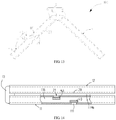
- the bendable body 13 includes a base 131, a first movable assembly 132, and a second movable assembly 133.
- the base 131 is rotatably connected between the first connection end 112 and the second connection end 121.
- the first movable assembly 132 is retractable.
- the first movable assembly 132 has a first edge rotatably connected to the first body 11 and a second edge opposite the first edge rotatably connected to the base 131.
- the second movable assembly 133 is retractable.
- the second movable assembly 133 has a first edge rotatably connected to the second body 12 and a second edge opposite the first edge rotatably connected to the base 131.
- the first body 11 When the first body 11 is rotatable relative to the second body 12 to bend the flexible display screen 222, the first body 11 drives the first movable assembly 132 to rotate together and the second body 11 drives the second movable assembly 133 to rotate together.
- the first movable assembly 132, the second movable assembly 133, and the base 131 cooperatively define a receiving space 134 configured to receive a bent portion of the flexible display screen 222.
- the casing assembly 10 further includes a pair of first rotating arms 16 disposed at opposite ends of the first movable assembly 132.
- Each of the first rotating arms 16 includes a first end 161 fixedly attached to the first connection end 112 and a second end 162 rotatably attached to the base 131.
- the pair of first rotating arms 16 may drive the first body 11 to rotate relative to the base 131 for balancing the rotation of the first body 11 relative to the second body 12.
- the first movable assembly 132 further includes a first rotating member 1322 and a first support member 1323.
- the first rotating member 1322 is rotatably connected to the base 131.
- the casing assembly 10 further includes a pair of second rotating arms 17 disposed at opposite ends of the second movable assembly 133.
- Each of the second rotating arms 17 includes a first end 171 fixedly attached to the second connection end 121 and a second end 172 rotatably attached to the base 131.
- the pair of second rotating arms 17 drive the second body 12 to rotate relative to the base 131 for balancing the rotation of the second body 12 relative to the first body 11.
- the second movable assembly 133 further includes a second rotating member 1332 and a second supporting member 1333.
- the second rotating member 1332 is rotatably connected to the base 131.
- the first body 11 When the first body 11 is rotated toward the second body 12, the first body 11 drives the first support member 1323 to slide away from the first rotating member 1322 and the second body 12 drives the second support member 1333 to slide away from the second rotating member 1332.
- An end of the first support member 1323 away from the base 131 and an end of the second support member 1333 away from the base 131 are moved close to each other to support the flexible display screen 222.
- the receiving space 134 cooperatively defined by the first movable assembly 132, the second movable assembly 133, and the base 131 is with a larger size for receiving the bent portion of the flexible display screen 222.
- the first support member 1323 When the first body 11 is rotated away from the second body 12, the first support member 1323 is slid toward the first rotating member 1322, and the second support member 1333 is slid toward the second rotating member 1332.
- the first support member 1323 aligns with the second support member 1333, or is coplanar with the second support member 1333.
- the first support member 1323 and the second support member 1333 are respectively moved toward opposite edges of the base 131 to support the flexible display screen 222.
- the bendable body 13 has an outer surface 130 facing the flexible display screen 222, which forms a portion of the inner folding surface 14.
- the flexible display screen 222 is fixedly attached to the first side plate 115 and the second side plate 124.
- the flexible display screen 222 covers the first receiving cavity 116 and the second receiving cavity 125.
- the flexible display screen 222 is flexible.
- the flexible display screen 222 includes a bendable portion 221 corresponding to the bendable body 13. When the first body 11 is unfolded relative to the second body 12, that is, the foldable electronic apparatus 100 is in the unfolded state, the flexible display screen 222 is in a flat state and the bendable body 13 provides a flat support for the bendable portion 221.
- the bendable portion 221 has the largest curvature
- the flexible display screen 222 is in a folded state and is located between the first body 11 and the second body 12.
- the foldable electronic apparatus 100 further includes a first display unit 30 attached to the first body 11.
- the first display unit 30 is attached to the first support plate 114.
- the first display unit 30 is located at the second surface 11b of the first body 11 opposite the second body 12.
- the first display unit 30 may be used as a front display screen to display information.
- the flexible display screen 222 may be used as a front display screen to display information.
- the first display unit 30 includes a first display screen 31 and a transparent cover 32 disposed at the first display screen 31.
- the first display screen 31 has a display area 311 and a non-display area 312 connected the display area 311.
- the first acoustic opening 111 is defined in an area of the transparent cover 32 facing the non-display area 312 of the first display screen 31.
- the first sounder 40 is attached to the first body 11.
- the first sounder 40 is disposed in the first receiving cavity 116 and faces the first acoustic opening 111.
- the first sounder 40 may be a receiver. In this way, the sounder 40 may emit sounds through the first acoustic opening 111.
- the first sounder 40 may be a speaker, or an electronic component with the function of a receiver and a speaker.
- the foldable electronic apparatus 100 further includes a frame member 23 fixedly connected between the flexible display screen 222 and the casing assembly 10.
- the frame member 23 is configured to protect a periphery edge of the flexible display screen 222.
- the first frame 231 and the second frame 232 both are substantially U-shaped.
- the first frame 231 is attached to the first body 11 and the second frame 232 is attached to the second body 12.
- the first frame 231 and the second frame 232 cooperatively form a rectangular structure.
- the first frame 231 may be attached to an edge of the first side plate 115 away from the first support plate 114 by screws, adhesives, snaps, or the like.
- the second frame 232 may be attached to an edge of the second side plate 124 away from the second support plate 123 by screws, adhesives, snaps, or the like.
- the first frame 231 includes a first board 2311, a second board 2312 disposed opposite the first board 2311, and a third board 2313 connecting the first board 2311 and the second board 2312.
- the third board 2313 is located adjacent to the first free end 113.
- the first board 2311, the second board 2312, and the third board 2313 are attached to the flexible display screen 222.
- the second frame 232 includes a first board 2321, a second board 2322 disposed opposite the first board 2321, and a third board 2323 connecting the first board 2321 and the second board 2322.
- the second board 2322 aligns with the second board 2312.
- the third board 2323 is located adjacent to the second free end 122.
- the second acoustic opening 21 may be defined in the frame member 23, that is, the second acoustic opening 21 may be defined in the first frame 231 or the second frame 232.
- the second sounder 50 may be a speaker.
- the foldable electronic apparatus 100 may emit sounds by the second sounder 50 through the second acoustic opening 21, such as playing music, sound prompt, or sound information.
- the second acoustic opening 21 is located between the first body 11 and the second body 12 to be concealed, thereby ensuring the foldable electronic apparatus 100 has a simple appearance.
- the second sounder 50 may also be a receiver, or an electronic component having the function of a receiver and a speaker.
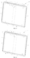
- the first acoustic opening 111 is defined in the first body 11 and the second acoustic opening 21 is defined in a portion of the flexible display screen assembly 20 facing the first body 11, that is, the first acoustic opening 111 and the second acoustic opening 21 are respectively defined in first body 11 and the second body 12 of the foldable electronic apparatus 100.
- the second acoustic opening 21 is defined in the second frame 232.
- the first sounder 40 is disposed in the first receiving cavity 116 and the second sounder 50 is disposed in the second receiving cavity 125, that is, the first sounder 40 and the second sounder 50 are respectively disposed in two separate receiving spaces, thereby preventing the first sounder 40 and the second sounder 50 from interfering with each other.
- the first acoustic opening 111 and the second acoustic opening 21 are respectively defined in first body 11 and the second body 12, thereby avoiding many acoustic openings defined in the first body 11 or the second body 12 to affect the appearance of the foldable electronic apparatus 100.
- the first body 11 and the second body 12 when the first body 11 and the second body 12 overlap with each other, that is, the foldable electronic apparatus 100 is the folded state, the first body 11 and the second body 12 defines a gap communicating with the second acoustic opening 21 to form a sound emitting channel 119a for communicating with outside.
- the gap is further located between the first frame 231 and the second frame 232 such that the frame member 23 may prevent foreign matter from entering into the gap to scratch the flexible display screen 222.
- the foldable electronic apparatus 100 may emit sounds through the sound emitting channel 119a and the second acoustic opening 21.
- the second acoustic opening 21 may be used as a acoustic opening of a speaker such that the foldable electronic apparatus 100 may emit sounds through the second acoustic opening 21.
- the user may make or answer the call through the sound emitting channel 119a and the second acoustic opening 21 in a hand-free manner.
- the second acoustic opening 21 on the second body 12 has an orthographic projection located between the second connection end 121 and the second free end 122.
- the second body 12 further has a third side 126 and a fourth side 127 disposed opposite the third side 126.
- the third side 126 connects the second connection end 121 and the second free end 122.
- the fourth side 127 connects the second connection end 121 and the second free end 122.
- the orthographic projection of the second acoustic opening 21 on the second body 12 is adjacent to the third side 126 of the second body 12.
- the second acoustic opening 21 is defined in the second frame 232.
- the first board 2321 of the second frame 230 on the second body 12 has an orthographic projection adjacent to the third side 126 of the second body 12.
- the second acoustic opening 21 is defined in the first board 2321.
- the second board 2322 on the second body 12 has an orthographic projection adjacent to the fourth side 127.
- the first body 11 includes a first side 117 and a second side 118 disposed opposite the first side 117.
- the first side 117 connects the first connection end 112 and the first free end 113.
- the second side 118 connects the first connection end 112 and the first free end 113.
- the first acoustic opening 111 may be defined adjacent to an edge of the first body 11 aligned with the third side 126.
- the first side 117 is an edge of the first body 11 aligned with the third side 126, that is, the first side 117 aligns with the third side 126.
- the second side 118 is an edge of the first body 11 aligned with the fourth side 127, that is, the second side 118 aligns with the fourth side 127.
- the first acoustic opening 111 is defined adjacent to the first side 117.
- the first acoustic opening 111 and the second acoustic opening 21 are both located at a top portion of the foldable electronic apparatus 100.
- the user may answer the call through the first acoustic opening 111 or the second acoustic opening 21 with his/her ear close to the top portion of the foldable electronic apparatus 100.
- the user may hear sounds emitted from the second acoustic opening 21 through the sound emitting channel 119a with his/her the ear closer to the top portion of the foldable electronic apparatus 100.
- the second acoustic opening 21 may be defined in the second frame 232.
- the second frame 232 faces the first body 11.
- the second acoustic opening 21 and the first display unit 30 of the first body 11 face the same direction.
- the sound from the second acoustic opening 21 may be transmitted toward the user, thereby preventing the content of the call from leaking when the user answers the call via the second acoustic opening 21.
- the first acoustic opening 111 may be defined adjacent to an edge of the first body 11 aligned with the fourth side 127.
- the first side 117 is an edge of the first body 11 aligned with the fourth side 127, that is, the first side 117 aligns with the fourth side 127.
- the second side 118 is an edge of the first body 11 aligned with the third side 126, that is, the second side 118 aligns with the third side 126.
- the first acoustic opening 111 and the second acoustic opening 21 are respectively located at opposite ends of the foldable electronic apparatus 100.
- a distance between the first sounder 40 and the second sounder 50 is long, which may prevent the first sounder 40 and the second sounder 50 from interfering with each other during operation.
- the foldable electronic apparatus 100 may further include a third acoustic opening 24 defined therein, and a third sounder 60 corresponding to the third acoustic opening 24.
- the third acoustic opening 24 is defined in the second frame 232.
- the third acoustic opening 24 on the second body 12 has an orthographic projection adjacent to the fourth side 127.
- the second acoustic opening 21 is defined in the first board 2321 of the second frame 232 and the third acoustic opening 24 is defined in the second board 2322 of the second frame 232.
- the second sounder 50 faces the second acoustic opening 21 and the third sounder 60 faces the third acoustic opening 24, which may produce a stereo effect when the foldable electronic apparatus 100 emits sounds.
- the second acoustic opening 21 may be defined in a portion of the flexible display screen assembly 20 facing the first body 11, and the first acoustic opening 111 may be defined in the first frame 231.
- the first acoustic opening 111 and the second acoustic opening 21 are located on the opposite sides of the first body 11 of the foldable electronic apparatus 100. Therefore, there is no acoustic opening defined in the portion the flexible display screen assembly 20 facing the first body 11, thereby ensuring the foldable electronic apparatus 100 has a simple appearance and improving the user experience.
- the first sounder 40 and the second sounder 50 are both disposed in the first receiving cavity 116 of the first body 11.
- the orthographic projection of the second acoustic opening 21 on the first body 11 is spaced from the first acoustic opening 111, that is, the first sounder 40 and the second sounder 50 are not stacked, which may reduce the thickness of the foldable electronic apparatus 100.
- the first body 11 and the second body 12 when the first body 11 and the second body 12 overlap with each other, that is, the foldable electronic apparatus 100 is the folded state, the first body 11 and the second body 12 defined a gap communicating with the second acoustic opening 21 to form a sound emitting channel 119b for communicating with outside.
- the gap is defined between the first frame 231 and the second frame 232.
- the foldable electronic apparatus 100 may emit sounds through the sound emitting channel 119b and the second acoustic opening 21. In this way, there is no need to define acoustic openings in the frame member, thereby ensuring the foldable electronic apparatus 100 has a simple appearance.
- the orthographic projection of the second acoustic opening 21 on the first body 11 at least partially overlaps with the first acoustic opening 111.
- the first sounder 40 includes a first sounding portion 41 and a second sounding portion 42 disposed opposite the first sounding portion 41.
- the first sounding portion 41 faces the first acoustic opening 111
- the second sounding portion 42 faces the second acoustic opening 21.
- the first acoustic opening 111 and the second acoustic opening 21 both correspond to the sounder 40, thereby reducing the thickness of the folded electronic device 100.
- the first acoustic opening 111 may be defined in the first body 11 adjacent to the first side 117.
- the second acoustic opening 21 may be defined in the first frame 231.
- the first board 2311 on the first body 11 has an orthographic projection adjacent to the first side 117
- the second board 2312 on the first body 11 has an orthographic projection adjacent to the second side 118.
- the third board 2313 is attached to the first free end 113.
- the first board 2311, the second board 2312, and the third board 2313 are attached to the edge of the flexible display screen 222.
- the orthographic projection of the second acoustic opening 21 on the first body 11 is adjacent to the first side 117.
- the first acoustic opening 111 is defined in the first board 2311.
- the first acoustic opening 111 and the second acoustic opening 21 are both close to the top portion of the foldable electronic apparatus 100. In this way, the user may answer the call through the first acoustic opening 111 or the second acoustic opening 21 with his/her ear close to the top portion of the foldable electronic apparatus 100.
- the orthographic projection of the second acoustic opening 21 on the first body 11 may be adjacent to the second side 118.
- the first acoustic opening 111 is defined in the second board 2312.
- the first acoustic opening 111 and the second acoustic opening 21 are located at opposite ends of the foldable electronic apparatus 100.
- the first sounder 40 faces the first acoustic opening 111
- the second sounder 50 faces the second acoustic opening 21.
- a distance between the first sounder 40 and the second sounder 50 is long, which may prevent the first sounder 40 and the second sounder 50 from interfering with each other during operation.
- the flexible display screen assembly 20 further includes a third acoustic opening 24 defined in the portion of the flexible display screen assembly 20 facing the first body 11.
- the third acoustic opening 24 on the first body 11 has an orthographic projection adjacent to the first side 117.
- the third acoustic opening 24 is defined in the first board 2311.
- the third sounder 60 may be a speaker.
- the second sounder 50 faces the second acoustic opening 21 and the third sounder 60 faces the third acoustic opening 24, which may produce a stereo effect when the foldable electronic apparatus 100 emits sounds.
- the second body 12 and the first body 11 defines a gap communicating with the second acoustic opening 21 to form a sound emitting channel for communicating with outside.
- the foldable electronic apparatus 100 may emit sounds through the sound emitting channels, the second acoustic opening 21, and the third acoustic opening 24, which may produce a stereo effect and ensure the quality of the sounds.
- the second acoustic opening 21 is defined in the third board 2313.
- Embodiment 2 which does not describe a way of carrying out the invention claimed.
- a foldable electronic apparatus 200 according to a second embodiment of the present disclosure is provided.
- the foldable electronic apparatus 200 in the second embodiment is different from the foldable electronic apparatus 100 in the first embodiment in that a transparent cover 223 disposed at a side of the flexible display screen 222 opposite the casing assembly 10, and the flexible display screen 222 including a first display area 224, a first non-display area 225 connecting the first display area 224, and a second non-display area 226.
- the second acoustic opening 21 is defined in the transparent cover 223.
- the transparent cover 223 is flexible.
- the second acoustic opening 21 is defined in a portion of the transparent cover 223 facing the first non-display area 225.
- the flexible display screen 222 is attached to and located between the first free end 113 and the second free end 122 of the casing assembly 10.
- the second non-display area 226 is connected to an edge of the first display area 224 away from the first non-display area 225.
- the first non-display area 225 is located adjacent to the first free end 113 of the flexible display screen 222, and the second non-display area 226 is located adjacent to the second free end 122 of the flexible display screen 222.
- the second acoustic opening 21 is defined in a portion the first non-display area 225 facing the transparent cover 223, which may fully utilize the space of foldable electronic apparatus 200 and avoid acoustic openings defined in the casing assembly, thereby ensuring the foldable electronic apparatus 200 has a simple appearance.
- the third acoustic opening 24 is defined in a portion of the transparent cover 223 facing the second non-display area 226. Therefore, the foldable electronic apparatus 200 may emit sounds by the second sounder 50 facing the second acoustic opening 21 and the third sounder 60 facing the third acoustic opening 24, which produces a stereo effect.
- a method for controlling the foldable electronic apparatus includes operations at the following blocks.
- the foldable electronic apparatus may remind the user by playing a ring tone or vibrating.
- sensors such as Hall sensors, distance sensors, or an angle sensor, are disposed at the first body 11 and the second body 12 for sensing the rotation angle of the first body 11 relative to the second body 12.
- the first threshold is a preset value corresponding to the angle between the first body 11 and the second body 12 when the foldable electronic apparatus is in the folded state.
- the second threshold is a preset value corresponding to the angle between the first body 11 and the second body 12 when the foldable electronic apparatus is in the unfolded state.
- the sensors may be disposed at the bendable body 13.
- the first sounder 40 is controlled to emit sounds through the first acoustic opening 111.
- the processor may control the first display unit 30 disposed at the first body 11 to display information to remind the user there is an incoming call.
- the foldable electronic apparatus may receive the first operation instruction through a touch display screen, a light sensor, a microphone, a mechanical button, or the like.
- the second sounder 50 is controlled to emit sounds through the second acoustic opening 21.
- the processor may control the flexible display screen 222 to display information to remind the user there is an incoming call.
- the foldable electronic apparatus may receive the second operation instruction through a touch display screen, a light sensor, a microphone, a mechanical button, or the like.
- a method for controlling a foldable electronic apparatus includes operations at the following blocks.
- the foldable electronic apparatus may remind a user by playing a ring tone or vibrating.
- the first sounder when receiving the first operation instruction, is controlled to emit sounds through the first acoustic opening when the rotation angle of the first body relative to the second body equals the first threshold.
- the second sounder when receiving the first rotation operation instruction, is controlled to emit sounds through the second acoustic opening when the rotation angle of the first body relative to the second body equals the first threshold.
- the first rotation operation instruction is generated in response to unfolding the foldable electronic apparatus.
- the first body 11 is further determined whether to be rotated away from the second body 12 when the rotation angle of the first body relative to the second body equals the first threshold.
- the processor controls the second sounder 50 to emit sounds through the second acoustic opening 21.
- the first body 11 is determined to be rotated away from the second body 12 based on whether the angle between the first body 11 and the second body 12 is increased and whether an increases in angle equals a first preset rotation value.
- the second sounder when receiving the second operation instruction, is controlled to emit sounds through the second acoustic opening when the rotation angle of the first body relative to the second body equals the second threshold.
- the first sounder when receiving the second rotation operation instruction, is controlled to emit sounds through the first acoustic opening when the rotation angle of the first body relative to the second body equals the second threshold.
- the second rotation operation instruction is generated in response to folding the foldable electronic apparatus when the rotation angle of the first body relative to the second body equals the second threshold.
- the first body 11 is further determined to be rotated toward the second body 12.
- the processor controls the first sounder 40 to emit sounds through the first acoustic opening 111.
- the first body 11 is determined to be rotated toward the second body 12 based on whether the angle between the first body 11 and the second body 12 is decreased and whether a decrease in angle equals a second preset rotation value.
- the first acoustic opening is defined in the second side of the first body opposite the inner folding surface and the second acoustic opening is defined in the side of the foldable electronic apparatus where the inner folding surface is located, which allows the foldable electronic apparatus to selectively emit sounds through the first acoustic opening or the second acoustic opening when making and answering the call according to the positional relationship between the first body and the second body, thereby meeting call requirements of the foldable electronic apparatus in different application scenarios and improving the user experience.
Landscapes
- Engineering & Computer Science (AREA)
- Computer Hardware Design (AREA)
- Theoretical Computer Science (AREA)
- Signal Processing (AREA)
- General Engineering & Computer Science (AREA)
- Physics & Mathematics (AREA)
- Human Computer Interaction (AREA)
- General Physics & Mathematics (AREA)
- Mechanical Engineering (AREA)
- Mathematical Physics (AREA)
- Telephone Set Structure (AREA)
- Telephone Function (AREA)
Claims (15)
- Faltbare elektronische Vorrichtung (100, 200), umfassend:
eine Gehäuseanordnung (10), umfassend:einen ersten Körper (11);einen zweiten Körper (12); undeinen biegbaren Körper (13), der drehbar zwischen dem ersten Körper (11) und dem zweiten Körper (12) verbunden ist;wobei der erste Körper (11) über den biegbaren Körper (13) relativ zum zweiten Körper (12) drehbar ist, um die faltbare elektronische Vorrichtung (100, 200) zwischen einem gefalteten Zustand und einem ungefalteten Zustand zu wechseln, wobei im gefalteten Zustand der erste Körper (11) und der zweite Körper (12) einander überlappen und im ungefalteten Zustand der erste Körper (11) relativ zum zweiten Körper (12) ungefaltet ist;der erste Körper (11) eine erste Oberfläche (11a) aufweist, wobei die erste Oberfläche (11a) einer ersten Oberfläche (12a) des zweiten Körpers (12) gegenüberliegt, wenn der erste Körper (11) und der zweite Körper (12) einander überlappen, und die erste Oberfläche (11a) des ersten Körpers (11) und die erste Oberfläche (12a) des zweiten Körpers (12) zusammenwirkend einen Abschnitt einer inneren Faltfläche (14) der Gehäuseanordnung (10) bilden; undeine flexible Anzeigebildschirmanordnung (20), die an der inneren Faltfläche (14) angeordnet ist;wobei die faltbare elektronische Vorrichtung (100, 200) ferner eine erste akustische Öffnung (111) im ersten Körper (11) und eine zweite akustische Öffnung (21) im zweiten Körper (12) definiert, wobei die erste akustische Öffnung (111) in einer zweiten Oberfläche (11b) des ersten Körpers (11) gegenüber der ersten Oberfläche (11a) des ersten Körpers (11) definiert ist und die zweite akustische Öffnung (21) in einer Seite der faltbaren elektronischen Vorrichtung (100, 200) definiert ist, wo sich die innere Faltfläche (14) befindet; undwobei die faltbare elektronische Vorrichtung (100, 200) dazu eingerichtet ist, Töne durch die erste akustische Öffnung (111) abzugeben, wenn sich die faltbare elektronische Vorrichtung (100, 200) im gefalteten Zustand befindet, und Töne durch die zweite akustische Öffnung (21) abzugeben, wenn sich die faltbare elektronische Vorrichtung (100, 200) im ungefalteten Zustand befindet. - Faltbare elektronische Vorrichtung (100, 200) gemäß Anspruch 1, wobei der erste Körper (11) ein erstes Verbindungsende (112), das den biegbaren Körper (13) verbindet, ein erstes freies Ende (113), das gegenüber dem ersten Verbindungsende (112) angeordnet ist, und eine erste Seite (117), die das erste Verbindungsende (112) und das erste freie Ende (113) verbindet, aufweist; wobei die erste akustische Öffnung (111) an die erste Seite (117) angrenzt.
- Faltbare elektronische Vorrichtung (100, 200) gemäß Anspruch 2, wobei die zweite akustische Öffnung (21) am ersten Körper (11) eine orthogonale Projektion aufweist, die von der ersten akustischen Öffnung (111) beabstandet ist.
- Faltbare elektronische Vorrichtung (100, 200) gemäß Anspruch 3, wobei die orthogonale Projektion der zweiten akustischen Öffnung (21) auf dem ersten Körper (11) an die erste Seite (117) angrenzt.
- Faltbare elektronische Vorrichtung (100, 200) gemäß Anspruch 3, wobei der erste Körper (11) ferner eine zweite Seite (118) gegenüber der ersten Seite (117) aufweist und die orthogonale Projektion der zweiten akustischen Öffnung (21) auf dem ersten Körper (11) an die zweite Seite (118) angrenzt.
- Faltbare elektronische Vorrichtung (100, 200) gemäß Anspruch 2, die ferner eine dritte akustische Öffnung (24) in einem Abschnitt einer flexiblen Anzeigebildschirmanordnung (22) definiert, die dem ersten Körper (11) zugewandt ist, wobei die dritte akustische Öffnung (24) auf dem ersten Körper (11) eine orthogonale Projektion angrenzend an die erste Seite (117) aufweist.
- Faltbare elektronische Vorrichtung (100, 200) gemäß Anspruch 1, wobei, wenn der erste Körper (11) und der zweite Körper (12) einander überlappen, der erste Körper (11) und der zweite Körper (12) einen Spalt definieren, der mit der zweiten akustischen Öffnung (21) in Verbindung steht, um einen schallabstrahlenden Kanal (119a) zum Kommunizieren mit der Umgebung zu bilden.
- Faltbare elektronische Vorrichtung (100, 200) gemäß Anspruch 1, wobei der zweite Körper (12) ein zweites Verbindungsende (121), das mit dem biegbaren Körper (13) verbunden ist, und ein zweites freies Ende (122) aufweist, das gegenüber dem zweiten Verbindungsende (121) angeordnet ist; die zweite akustische Öffnung (21) sich zwischen dem zweiten Verbindungsende (121) und dem zweiten freien Ende (122) befindet.
- Faltbare elektronische Vorrichtung (100, 200) gemäß Anspruch 8, wobei der zweite Körper (12) ferner eine dritte Seite (126) aufweist, die das zweite Verbindungsende (121) und das zweite freie Ende (122) verbindet; die zweite akustische Öffnung (21) an die dritte Seite (126) angrenzt.
- Faltbare elektronische Vorrichtung (100, 200) gemäß Anspruch 9, wobei die erste akustische Öffnung (111) an eine Kante des ersten Körpers (11) angrenzt, die mit der dritten Seite (126) ausgerichtet ist.
- Faltbare elektronische Vorrichtung (100, 200) gemäß Anspruch 9, wobei der zweite Körper (12) ferner eine vierte Seite (127) gegenüber der dritten Seite (126) aufweist; die erste akustische Öffnung (111) an eine Kante des ersten Körpers (11) angrenzt, die mit der vierten Seite (127) ausgerichtet ist.
- Faltbare elektronische Vorrichtung (100, 200) gemäß Anspruch 11, die ferner eine dritte akustische Öffnung (24) im zweiten Körper (12) definiert, wobei die dritte akustische Öffnung (24) an die vierte Seite (127) angrenzt.
- Faltbare elektronische Vorrichtung (100, 200) gemäß Anspruch 1, wobei der biegbare Körper (13) eine erste bewegbare Anordnung (132), eine zweite bewegbare Anordnung (133) und eine Basis (131) umfasst, die drehbar zwischen einem ersten Verbindungsende (112) des ersten Körpers (11) und einem zweiten Verbindungsende (121) des zweiten Körpers (12) verbunden ist, wobei die erste bewegbare Anordnung (132) und die zweite bewegbare Anordnung (133) einziehbar sind.
- Faltbare elektronische Vorrichtung (100, 200) gemäß Anspruch 13, wobei die erste bewegbare Anordnung (132) ferner ein erstes Drehelement (1322), das drehbar mit der Basis (131) verbunden ist, und ein erstes Stützelement (1323) umfasst; die zweite bewegbare Anordnung (133) ferner ein zweites Drehelement (1332) umfasst, das drehbar mit der Basis (131) verbunden ist; der erste Körper (11) das erste Stützelement (1323) antreibt, um vom ersten Drehelement (1322) weg zu gleiten, und der zweite Körper (12) das zweite Stützelement (1333) antreibt, um vom zweiten Drehelement (1332) weg zu gleiten, wenn der erste Körper (11) zum zweiten Körper (12) hin gedreht wird; das erste Stützelement (1323) zum ersten Drehelement (1322) hin und das zweite Stützelement (1333) zum zweiten Drehelement (1332) hin gleitet, wenn der erste Körper (11) vom zweiten Körper (12) weg gedreht wird.
- Verfahren zum Steuern der faltbaren elektronischen Vorrichtung (100, 200) gemäß einem der Ansprüche 1 bis 14, wobei das Verfahren umfasst:Bestimmen, ob bei einem eingehenden Anruf ein Drehwinkel des ersten Körpers (11) relativ zum zweiten Körper (12) gleich einem ersten Schwellenwert oder einem zweiten Schwellenwert ist;Steuern eines ersten Schallgebers (40), um Töne durch die erste akustische Öffnung (111) zu emittieren, wenn der Drehwinkel des ersten Körpers (11) relativ zum zweiten Körper (12) gleich dem ersten Schwellenwert ist; undSteuern eines zweiten Schallgebers (50), um Töne durch die zweite akustische Öffnung (21) zu emittieren, wenn der Drehwinkel des ersten Körpers (11) relativ zum zweiten Körper (12) gleich dem zweiten Schwellenwert ist.
Applications Claiming Priority (1)
| Application Number | Priority Date | Filing Date | Title |
|---|---|---|---|
| CN201810776032.9A CN110714976A (zh) | 2018-07-13 | 2018-07-13 | 折叠式电子设备及折叠式电子设备的控制方法 |
Publications (2)
| Publication Number | Publication Date |
|---|---|
| EP3595273A1 EP3595273A1 (de) | 2020-01-15 |
| EP3595273B1 true EP3595273B1 (de) | 2022-01-12 |
Family
ID=67180528
Family Applications (1)
| Application Number | Title | Priority Date | Filing Date |
|---|---|---|---|
| EP19183892.9A Active EP3595273B1 (de) | 2018-07-13 | 2019-07-02 | Faltbare elektronische vorrichtung und verfahren zur steuerung einer faltbaren elektronischen vorrichtung |
Country Status (4)
| Country | Link |
|---|---|
| US (1) | US10536566B1 (de) |
| EP (1) | EP3595273B1 (de) |
| CN (1) | CN110714976A (de) |
| WO (1) | WO2020011036A1 (de) |
Families Citing this family (16)
| Publication number | Priority date | Publication date | Assignee | Title |
|---|---|---|---|---|
| TWI687795B (zh) * | 2018-09-27 | 2020-03-11 | 兆利科技工業股份有限公司 | 折疊式裝置的轉軸模組 |
| CN210429140U (zh) * | 2019-11-27 | 2020-04-28 | 北京京东方光电科技有限公司 | 显示装置 |
| CN110971728B (zh) * | 2019-12-13 | 2021-04-09 | Oppo广东移动通信有限公司 | 折叠装置及电子设备 |
| KR20210099974A (ko) * | 2020-02-05 | 2021-08-13 | 삼성전자주식회사 | 음향 경로를 포함하는 전자 장치 |
| KR102741319B1 (ko) * | 2020-02-10 | 2024-12-12 | 삼성전자주식회사 | 전자 장치 및 전자 장치의 음성 녹음 방법 |
| CN115199638B (zh) | 2020-04-30 | 2024-02-13 | Oppo广东移动通信有限公司 | 电子组件、电子设备 |
| CN113760040A (zh) * | 2020-06-02 | 2021-12-07 | Oppo广东移动通信有限公司 | 形态变化的提醒方法、装置、终端及存储介质 |
| CN111681548B (zh) * | 2020-06-15 | 2021-12-28 | 武汉华星光电半导体显示技术有限公司 | 可折叠显示装置 |
| USD1040776S1 (en) * | 2020-07-10 | 2024-09-03 | Huawei Technologies Co., Ltd. | Mobile phone |
| US12267451B2 (en) * | 2020-08-27 | 2025-04-01 | Lg Electronics Inc. | Flexible display device |
| CN112261180B (zh) * | 2020-10-12 | 2022-03-08 | 维沃移动通信有限公司 | 电子设备、电子设备的控制方法 |
| KR102686705B1 (ko) | 2021-01-29 | 2024-07-22 | 삼성전자주식회사 | 스피커 모듈을 포함하는 전자 장치 |
| KR102933187B1 (ko) * | 2021-02-04 | 2026-03-03 | 삼성전자주식회사 | 음향 부품 및 이를 포함하는 전자 장치 |
| CN113099014B (zh) * | 2021-04-26 | 2023-03-21 | 维沃移动通信有限公司 | 电子设备 |
| CN113311909B (zh) * | 2021-05-26 | 2024-05-10 | 维沃移动通信有限公司 | 电子设备、音频控制方法、音频控制装置及可读存储介质 |
| CN116838704A (zh) * | 2022-03-24 | 2023-10-03 | Oppo广东移动通信有限公司 | 转轴装置、折叠壳体及电子设备 |
Family Cites Families (16)
| Publication number | Priority date | Publication date | Assignee | Title |
|---|---|---|---|---|
| JP4170013B2 (ja) * | 2002-04-18 | 2008-10-22 | 松下電器産業株式会社 | 電子機器 |
| EP1531606A1 (de) | 2002-06-07 | 2005-05-18 | Matsushita Electric Industrial Co., Ltd. | Klappbares mobiltelefon |
| JP4443192B2 (ja) * | 2003-11-06 | 2010-03-31 | 京セラ株式会社 | 折り畳み式携帯端末機 |
| US7664539B2 (en) * | 2003-11-06 | 2010-02-16 | Kyocera Corporation | Foldable portable terminal |
| JP4205105B2 (ja) * | 2006-01-04 | 2009-01-07 | 株式会社東芝 | 携帯電子機器 |
| US20070268264A1 (en) * | 2006-05-16 | 2007-11-22 | Nokia Corporation | Electronic devices |
| KR101494555B1 (ko) * | 2010-08-19 | 2015-02-17 | 애플 인크. | 휴대용 전자 장치 |
| EP2595029A1 (de) * | 2011-11-15 | 2013-05-22 | Research In Motion Limited | Tragbare elektronische Vorrichtung mit einer flexiblen Anzeige |
| JP2016129271A (ja) * | 2013-04-26 | 2016-07-14 | 京セラ株式会社 | 電子機器 |
| KR102309411B1 (ko) * | 2014-10-27 | 2021-10-06 | 엘지전자 주식회사 | 휴대 전자기기 |
| WO2016157105A1 (en) * | 2015-03-31 | 2016-10-06 | Fisher & Paykel Healthcare Limited | A user interface and system for supplying gases to an airway |
| KR102433269B1 (ko) * | 2016-01-18 | 2022-08-17 | 삼성전자 주식회사 | 플렉서블 디스플레이 장치 및 디스플레이 제어 방법 |
| CN107025006A (zh) * | 2016-01-29 | 2017-08-08 | 联想(北京)有限公司 | 一种信息处理方法及电子设备 |
| KR102485361B1 (ko) * | 2016-10-13 | 2023-01-06 | 삼성전자주식회사 | 플렉서블 하우징을 포함하는 전자 장치 |
| CN206559426U (zh) * | 2017-03-24 | 2017-10-13 | 广东欧珀移动通信有限公司 | 转轴组件、折叠屏组件及移动终端 |
| CN207184559U (zh) * | 2017-09-05 | 2018-04-03 | 广东欧珀移动通信有限公司 | 柔性屏折叠式移动终端 |
-
2018
- 2018-07-13 CN CN201810776032.9A patent/CN110714976A/zh active Pending
-
2019
- 2019-06-28 WO PCT/CN2019/093845 patent/WO2020011036A1/en not_active Ceased
- 2019-07-02 EP EP19183892.9A patent/EP3595273B1/de active Active
- 2019-07-11 US US16/509,439 patent/US10536566B1/en active Active
Also Published As
| Publication number | Publication date |
|---|---|
| US20200021674A1 (en) | 2020-01-16 |
| WO2020011036A1 (en) | 2020-01-16 |
| US10536566B1 (en) | 2020-01-14 |
| CN110714976A (zh) | 2020-01-21 |
| EP3595273A1 (de) | 2020-01-15 |
Similar Documents
| Publication | Publication Date | Title |
|---|---|---|
| EP3595273B1 (de) | Faltbare elektronische vorrichtung und verfahren zur steuerung einer faltbaren elektronischen vorrichtung | |
| JP3675430B2 (ja) | 携帯電話機 | |
| EP1758347B1 (de) | Portables Kommunikationsendgerät mit Mitteln zur Kontrolle der Tonausgabe | |
| KR102468709B1 (ko) | 키 모듈과 이를 구비한 이동 단말기 및 키 모듈 조립 방법 | |
| CN109547588A (zh) | 移动终端 | |
| KR20200132016A (ko) | 복수 개의 스피커들을 포함하는 전자 장치 및 그 제어 방법 | |
| CN110764730A (zh) | 播放音频数据的方法和装置 | |
| JP2006157464A (ja) | 音響装置 | |
| JP2009246820A (ja) | 携帯端末装置 | |
| EP3646576B1 (de) | Kombination aus mikrofon und beleuchtungsvorrichtung und datenverarbeitungsvorrichtung damit | |
| KR101474459B1 (ko) | 휴대 단말기 | |
| CN110324452A (zh) | 电子装置及电子装置的控制方法 | |
| KR20210099974A (ko) | 음향 경로를 포함하는 전자 장치 | |
| WO2019228164A1 (zh) | 移动终端控制方法及移动终端 | |
| KR102450587B1 (ko) | 사운드박스 어셈블리, 디스플레이 장치, 오디오 출력 방법 및 장치 | |
| CN117579730A (zh) | 电子设备 | |
| JP4123994B2 (ja) | 携帯電話機 | |
| JP2011259182A (ja) | 携帯端末装置 | |
| CN110312004B (zh) | 电子装置及电子装置的控制方法 | |
| JP5100679B2 (ja) | 通話装置における受話口の構造および携帯電話機 | |
| KR20210046323A (ko) | 이동 단말기 및 이에 결합하는 보조 장치 | |
| CN102970631A (zh) | 信息处理设备和信息处理方法 | |
| HK40019553A (en) | Folding electronic device and control method of folding electronic device | |
| JP6758455B1 (ja) | 電子機器 | |
| JP2010087638A (ja) | 電子機器 |
Legal Events
| Date | Code | Title | Description |
|---|---|---|---|
| PUAI | Public reference made under article 153(3) epc to a published international application that has entered the european phase |
Free format text: ORIGINAL CODE: 0009012 |
|
| STAA | Information on the status of an ep patent application or granted ep patent |
Free format text: STATUS: THE APPLICATION HAS BEEN PUBLISHED |
|
| AK | Designated contracting states |
Kind code of ref document: A1 Designated state(s): AL AT BE BG CH CY CZ DE DK EE ES FI FR GB GR HR HU IE IS IT LI LT LU LV MC MK MT NL NO PL PT RO RS SE SI SK SM TR |
|
| AX | Request for extension of the european patent |
Extension state: BA ME |
|
| STAA | Information on the status of an ep patent application or granted ep patent |
Free format text: STATUS: REQUEST FOR EXAMINATION WAS MADE |
|
| 17P | Request for examination filed |
Effective date: 20200406 |
|
| RBV | Designated contracting states (corrected) |
Designated state(s): AL AT BE BG CH CY CZ DE DK EE ES FI FR GB GR HR HU IE IS IT LI LT LU LV MC MK MT NL NO PL PT RO RS SE SI SK SM TR |
|
| GRAP | Despatch of communication of intention to grant a patent |
Free format text: ORIGINAL CODE: EPIDOSNIGR1 |
|
| STAA | Information on the status of an ep patent application or granted ep patent |
Free format text: STATUS: GRANT OF PATENT IS INTENDED |
|
| INTG | Intention to grant announced |
Effective date: 20210604 |
|
| GRAJ | Information related to disapproval of communication of intention to grant by the applicant or resumption of examination proceedings by the epo deleted |
Free format text: ORIGINAL CODE: EPIDOSDIGR1 |
|
| STAA | Information on the status of an ep patent application or granted ep patent |
Free format text: STATUS: REQUEST FOR EXAMINATION WAS MADE |
|
| GRAP | Despatch of communication of intention to grant a patent |
Free format text: ORIGINAL CODE: EPIDOSNIGR1 |
|
| STAA | Information on the status of an ep patent application or granted ep patent |
Free format text: STATUS: GRANT OF PATENT IS INTENDED |
|
| INTC | Intention to grant announced (deleted) | ||
| GRAS | Grant fee paid |
Free format text: ORIGINAL CODE: EPIDOSNIGR3 |
|
| GRAA | (expected) grant |
Free format text: ORIGINAL CODE: 0009210 |
|
| STAA | Information on the status of an ep patent application or granted ep patent |
Free format text: STATUS: THE PATENT HAS BEEN GRANTED |
|
| INTG | Intention to grant announced |
Effective date: 20211116 |
|
| AK | Designated contracting states |
Kind code of ref document: B1 Designated state(s): AL AT BE BG CH CY CZ DE DK EE ES FI FR GB GR HR HU IE IS IT LI LT LU LV MC MK MT NL NO PL PT RO RS SE SI SK SM TR |
|
| REG | Reference to a national code |
Ref country code: GB Ref legal event code: FG4D |
|
| REG | Reference to a national code |
Ref country code: CH Ref legal event code: EP |
|
| REG | Reference to a national code |
Ref country code: DE Ref legal event code: R096 Ref document number: 602019010805 Country of ref document: DE |
|
| REG | Reference to a national code |
Ref country code: IE Ref legal event code: FG4D |
|
| REG | Reference to a national code |
Ref country code: AT Ref legal event code: REF Ref document number: 1463132 Country of ref document: AT Kind code of ref document: T Effective date: 20220215 |
|
| REG | Reference to a national code |
Ref country code: LT Ref legal event code: MG9D |
|
| REG | Reference to a national code |
Ref country code: NL Ref legal event code: MP Effective date: 20220112 |
|
| REG | Reference to a national code |
Ref country code: AT Ref legal event code: MK05 Ref document number: 1463132 Country of ref document: AT Kind code of ref document: T Effective date: 20220112 |
|
| PG25 | Lapsed in a contracting state [announced via postgrant information from national office to epo] |
Ref country code: NL Free format text: LAPSE BECAUSE OF FAILURE TO SUBMIT A TRANSLATION OF THE DESCRIPTION OR TO PAY THE FEE WITHIN THE PRESCRIBED TIME-LIMIT Effective date: 20220112 |
|
| PG25 | Lapsed in a contracting state [announced via postgrant information from national office to epo] |
Ref country code: SE Free format text: LAPSE BECAUSE OF FAILURE TO SUBMIT A TRANSLATION OF THE DESCRIPTION OR TO PAY THE FEE WITHIN THE PRESCRIBED TIME-LIMIT Effective date: 20220112 Ref country code: RS Free format text: LAPSE BECAUSE OF FAILURE TO SUBMIT A TRANSLATION OF THE DESCRIPTION OR TO PAY THE FEE WITHIN THE PRESCRIBED TIME-LIMIT Effective date: 20220112 Ref country code: PT Free format text: LAPSE BECAUSE OF FAILURE TO SUBMIT A TRANSLATION OF THE DESCRIPTION OR TO PAY THE FEE WITHIN THE PRESCRIBED TIME-LIMIT Effective date: 20220512 Ref country code: NO Free format text: LAPSE BECAUSE OF FAILURE TO SUBMIT A TRANSLATION OF THE DESCRIPTION OR TO PAY THE FEE WITHIN THE PRESCRIBED TIME-LIMIT Effective date: 20220412 Ref country code: LT Free format text: LAPSE BECAUSE OF FAILURE TO SUBMIT A TRANSLATION OF THE DESCRIPTION OR TO PAY THE FEE WITHIN THE PRESCRIBED TIME-LIMIT Effective date: 20220112 Ref country code: HR Free format text: LAPSE BECAUSE OF FAILURE TO SUBMIT A TRANSLATION OF THE DESCRIPTION OR TO PAY THE FEE WITHIN THE PRESCRIBED TIME-LIMIT Effective date: 20220112 Ref country code: ES Free format text: LAPSE BECAUSE OF FAILURE TO SUBMIT A TRANSLATION OF THE DESCRIPTION OR TO PAY THE FEE WITHIN THE PRESCRIBED TIME-LIMIT Effective date: 20220112 Ref country code: BG Free format text: LAPSE BECAUSE OF FAILURE TO SUBMIT A TRANSLATION OF THE DESCRIPTION OR TO PAY THE FEE WITHIN THE PRESCRIBED TIME-LIMIT Effective date: 20220412 |
|
| PG25 | Lapsed in a contracting state [announced via postgrant information from national office to epo] |
Ref country code: PL Free format text: LAPSE BECAUSE OF FAILURE TO SUBMIT A TRANSLATION OF THE DESCRIPTION OR TO PAY THE FEE WITHIN THE PRESCRIBED TIME-LIMIT Effective date: 20220112 Ref country code: LV Free format text: LAPSE BECAUSE OF FAILURE TO SUBMIT A TRANSLATION OF THE DESCRIPTION OR TO PAY THE FEE WITHIN THE PRESCRIBED TIME-LIMIT Effective date: 20220112 Ref country code: GR Free format text: LAPSE BECAUSE OF FAILURE TO SUBMIT A TRANSLATION OF THE DESCRIPTION OR TO PAY THE FEE WITHIN THE PRESCRIBED TIME-LIMIT Effective date: 20220413 Ref country code: FI Free format text: LAPSE BECAUSE OF FAILURE TO SUBMIT A TRANSLATION OF THE DESCRIPTION OR TO PAY THE FEE WITHIN THE PRESCRIBED TIME-LIMIT Effective date: 20220112 Ref country code: AT Free format text: LAPSE BECAUSE OF FAILURE TO SUBMIT A TRANSLATION OF THE DESCRIPTION OR TO PAY THE FEE WITHIN THE PRESCRIBED TIME-LIMIT Effective date: 20220112 |
|
| PG25 | Lapsed in a contracting state [announced via postgrant information from national office to epo] |
Ref country code: IS Free format text: LAPSE BECAUSE OF FAILURE TO SUBMIT A TRANSLATION OF THE DESCRIPTION OR TO PAY THE FEE WITHIN THE PRESCRIBED TIME-LIMIT Effective date: 20220512 |
|
| REG | Reference to a national code |
Ref country code: DE Ref legal event code: R097 Ref document number: 602019010805 Country of ref document: DE |
|
| PG25 | Lapsed in a contracting state [announced via postgrant information from national office to epo] |
Ref country code: SM Free format text: LAPSE BECAUSE OF FAILURE TO SUBMIT A TRANSLATION OF THE DESCRIPTION OR TO PAY THE FEE WITHIN THE PRESCRIBED TIME-LIMIT Effective date: 20220112 Ref country code: SK Free format text: LAPSE BECAUSE OF FAILURE TO SUBMIT A TRANSLATION OF THE DESCRIPTION OR TO PAY THE FEE WITHIN THE PRESCRIBED TIME-LIMIT Effective date: 20220112 Ref country code: RO Free format text: LAPSE BECAUSE OF FAILURE TO SUBMIT A TRANSLATION OF THE DESCRIPTION OR TO PAY THE FEE WITHIN THE PRESCRIBED TIME-LIMIT Effective date: 20220112 Ref country code: EE Free format text: LAPSE BECAUSE OF FAILURE TO SUBMIT A TRANSLATION OF THE DESCRIPTION OR TO PAY THE FEE WITHIN THE PRESCRIBED TIME-LIMIT Effective date: 20220112 Ref country code: DK Free format text: LAPSE BECAUSE OF FAILURE TO SUBMIT A TRANSLATION OF THE DESCRIPTION OR TO PAY THE FEE WITHIN THE PRESCRIBED TIME-LIMIT Effective date: 20220112 Ref country code: CZ Free format text: LAPSE BECAUSE OF FAILURE TO SUBMIT A TRANSLATION OF THE DESCRIPTION OR TO PAY THE FEE WITHIN THE PRESCRIBED TIME-LIMIT Effective date: 20220112 |
|
| PLBE | No opposition filed within time limit |
Free format text: ORIGINAL CODE: 0009261 |
|
| STAA | Information on the status of an ep patent application or granted ep patent |
Free format text: STATUS: NO OPPOSITION FILED WITHIN TIME LIMIT |
|
| PG25 | Lapsed in a contracting state [announced via postgrant information from national office to epo] |
Ref country code: AL Free format text: LAPSE BECAUSE OF FAILURE TO SUBMIT A TRANSLATION OF THE DESCRIPTION OR TO PAY THE FEE WITHIN THE PRESCRIBED TIME-LIMIT Effective date: 20220112 |
|
| 26N | No opposition filed |
Effective date: 20221013 |
|
| PG25 | Lapsed in a contracting state [announced via postgrant information from national office to epo] |
Ref country code: SI Free format text: LAPSE BECAUSE OF FAILURE TO SUBMIT A TRANSLATION OF THE DESCRIPTION OR TO PAY THE FEE WITHIN THE PRESCRIBED TIME-LIMIT Effective date: 20220112 Ref country code: MC Free format text: LAPSE BECAUSE OF FAILURE TO SUBMIT A TRANSLATION OF THE DESCRIPTION OR TO PAY THE FEE WITHIN THE PRESCRIBED TIME-LIMIT Effective date: 20220112 |
|
| REG | Reference to a national code |
Ref country code: CH Ref legal event code: PL |
|
| REG | Reference to a national code |
Ref country code: BE Ref legal event code: MM Effective date: 20220731 |
|
| PG25 | Lapsed in a contracting state [announced via postgrant information from national office to epo] |
Ref country code: LU Free format text: LAPSE BECAUSE OF NON-PAYMENT OF DUE FEES Effective date: 20220702 Ref country code: LI Free format text: LAPSE BECAUSE OF NON-PAYMENT OF DUE FEES Effective date: 20220731 Ref country code: CH Free format text: LAPSE BECAUSE OF NON-PAYMENT OF DUE FEES Effective date: 20220731 |
|
| PG25 | Lapsed in a contracting state [announced via postgrant information from national office to epo] |
Ref country code: BE Free format text: LAPSE BECAUSE OF NON-PAYMENT OF DUE FEES Effective date: 20220731 |
|
| P01 | Opt-out of the competence of the unified patent court (upc) registered |
Effective date: 20230412 |
|
| PG25 | Lapsed in a contracting state [announced via postgrant information from national office to epo] |
Ref country code: IT Free format text: LAPSE BECAUSE OF FAILURE TO SUBMIT A TRANSLATION OF THE DESCRIPTION OR TO PAY THE FEE WITHIN THE PRESCRIBED TIME-LIMIT Effective date: 20220112 Ref country code: IE Free format text: LAPSE BECAUSE OF NON-PAYMENT OF DUE FEES Effective date: 20220702 |
|
| PG25 | Lapsed in a contracting state [announced via postgrant information from national office to epo] |
Ref country code: HU Free format text: LAPSE BECAUSE OF FAILURE TO SUBMIT A TRANSLATION OF THE DESCRIPTION OR TO PAY THE FEE WITHIN THE PRESCRIBED TIME-LIMIT; INVALID AB INITIO Effective date: 20190702 |
|
| PG25 | Lapsed in a contracting state [announced via postgrant information from national office to epo] |
Ref country code: MK Free format text: LAPSE BECAUSE OF FAILURE TO SUBMIT A TRANSLATION OF THE DESCRIPTION OR TO PAY THE FEE WITHIN THE PRESCRIBED TIME-LIMIT Effective date: 20220112 Ref country code: CY Free format text: LAPSE BECAUSE OF FAILURE TO SUBMIT A TRANSLATION OF THE DESCRIPTION OR TO PAY THE FEE WITHIN THE PRESCRIBED TIME-LIMIT Effective date: 20220112 |
|
| PG25 | Lapsed in a contracting state [announced via postgrant information from national office to epo] |
Ref country code: TR Free format text: LAPSE BECAUSE OF FAILURE TO SUBMIT A TRANSLATION OF THE DESCRIPTION OR TO PAY THE FEE WITHIN THE PRESCRIBED TIME-LIMIT Effective date: 20220112 |
|
| PG25 | Lapsed in a contracting state [announced via postgrant information from national office to epo] |
Ref country code: MT Free format text: LAPSE BECAUSE OF FAILURE TO SUBMIT A TRANSLATION OF THE DESCRIPTION OR TO PAY THE FEE WITHIN THE PRESCRIBED TIME-LIMIT Effective date: 20220112 |
|
| PGFP | Annual fee paid to national office [announced via postgrant information from national office to epo] |
Ref country code: DE Payment date: 20250702 Year of fee payment: 7 |
|
| PGFP | Annual fee paid to national office [announced via postgrant information from national office to epo] |
Ref country code: GB Payment date: 20250703 Year of fee payment: 7 |
|
| PGFP | Annual fee paid to national office [announced via postgrant information from national office to epo] |
Ref country code: FR Payment date: 20250703 Year of fee payment: 7 |