EP3593886B1 - Kontaminationsfrei wechselbare filterpatrone - Google Patents
Kontaminationsfrei wechselbare filterpatrone Download PDFInfo
- Publication number
- EP3593886B1 EP3593886B1 EP19184947.0A EP19184947A EP3593886B1 EP 3593886 B1 EP3593886 B1 EP 3593886B1 EP 19184947 A EP19184947 A EP 19184947A EP 3593886 B1 EP3593886 B1 EP 3593886B1
- Authority
- EP
- European Patent Office
- Prior art keywords
- filter cartridge
- filter
- protective sheath
- air filter
- filter device
- Prior art date
- Legal status (The legal status is an assumption and is not a legal conclusion. Google has not performed a legal analysis and makes no representation as to the accuracy of the status listed.)
- Active
Links
Images


Classifications
-
- B—PERFORMING OPERATIONS; TRANSPORTING
- B01—PHYSICAL OR CHEMICAL PROCESSES OR APPARATUS IN GENERAL
- B01D—SEPARATION
- B01D46/00—Filters or filtering processes specially modified for separating dispersed particles from gases or vapours
- B01D46/24—Particle separators, e.g. dust precipitators, using rigid hollow filter bodies
- B01D46/2403—Particle separators, e.g. dust precipitators, using rigid hollow filter bodies characterised by the physical shape or structure of the filtering element
- B01D46/2411—Filter cartridges
- B01D46/2414—End caps including additional functions or special forms
-
- B—PERFORMING OPERATIONS; TRANSPORTING
- B01—PHYSICAL OR CHEMICAL PROCESSES OR APPARATUS IN GENERAL
- B01D—SEPARATION
- B01D46/00—Filters or filtering processes specially modified for separating dispersed particles from gases or vapours
- B01D46/0084—Filters or filtering processes specially modified for separating dispersed particles from gases or vapours provided with safety means
- B01D46/0091—Including arrangements for environmental or personal protection
-
- B—PERFORMING OPERATIONS; TRANSPORTING
- B01—PHYSICAL OR CHEMICAL PROCESSES OR APPARATUS IN GENERAL
- B01D—SEPARATION
- B01D46/00—Filters or filtering processes specially modified for separating dispersed particles from gases or vapours
- B01D46/52—Particle separators, e.g. dust precipitators, using filters embodying folded corrugated or wound sheet material
- B01D46/521—Particle separators, e.g. dust precipitators, using filters embodying folded corrugated or wound sheet material using folded, pleated material
-
- B—PERFORMING OPERATIONS; TRANSPORTING
- B01—PHYSICAL OR CHEMICAL PROCESSES OR APPARATUS IN GENERAL
- B01D—SEPARATION
- B01D46/00—Filters or filtering processes specially modified for separating dispersed particles from gases or vapours
- B01D46/88—Replacing filter elements
Definitions
- the present invention relates to an air filter device and a method for the contamination-free changing of a filter cartridge.
- Filter cartridges in particular disposable filter cartridges, are used in air filter devices, in particular in industrial filter systems such as suction systems for smoke and dust extraction and in room ventilation systems. Many industrial processes produce harmful smoke, dust or air that contains disruptive particles or gases, so that these contaminations are either sucked off and filtered from the air directly at the point of origin using suction arms or by means of an air filter device that is stationary in the room. The contamination collects in the filter cartridge, which has to be replaced after a certain period of time.
- the filter cartridges used for this purpose from the prior art generally have a circular cylindrical basic shape, the jacket of the cylindrical basic shape being formed from the filter material.
- the filter material is usually in the form of a pleated filter.
- the axis of rotation of the cylinder i.e. the longitudinal axis, is located in the air duct of the filter cartridge, through which the filtered air flows.
- the air to be cleaned flows to the filter cartridge from the outside and passes through the filter material into the air duct on the inside, while the particles to be separated from the air remain in the filter.
- the filter cartridge must be replaced with a new filter cartridge.
- a disadvantage of the air filter devices known from the prior art is that the person who replaces a clogged filter cartridge with a new filter cartridge comes into contact with the dirty, contaminated dirt side, ie the outside.
- the fastening of the filter cartridge with which it is held in the use position in the air filter device for example a suction device, has to be loosened.
- filter cartridges are so in built into the air filter device so that the longitudinal axis runs vertically.
- the filter cartridge is connected to the air filter device at one end or at both ends.
- the fastenings must be loosened through the relatively small filter change flap before removal, so that the person performing the change inevitably comes into contact with the dirty side of the filter material when loosening these fastenings.
- the removal process also causes the filter cartridge to vibrate, as a result of which particles adhering to the dirt side contaminate the room air.
- Suction devices are also known from the prior art which attempt to solve this problem by attaching a protective cover to the outside of the filter replacement flap, into which the filter cartridge can be pulled after the retaining fastenings have been loosened. Such devices are off DE 42 16 343 A1 known.
- US 2007/221585 A1 discloses a filter cartridge with a protective cover which is to be removed prior to insertion into an air filter device.
- a disadvantage of such devices is that the person performing the change comes into contact with the dirty side of the filter cartridge while loosening the fastenings with which the filter cartridge is fixed within the air filter device.
- the filter cartridge is pulled into the protective cover arranged outside the air filter device, particles are released from the dirt side, which are distributed within the air filter device and can be released into the room air through the replaceable flap before the new filter cartridge is inserted or remain inside the air filter device and can clog the subsequently inserted filter cartridge.
- the object of the invention is to provide an air filter device which overcomes the disadvantages known from the prior art.
- the object of the invention is thus to provide an air filter device whose filter cartridge can be changed without contamination.
- an air filter device in particular a suction device, comprising an exchangeable filter cartridge, the filter cartridge being filter material that forms a hollow cylinder, a first closing element that is arranged at the first end of the hollow cylinder, and a second closing element that is attached to the is arranged second end of the hollow cylinder, characterized in that the filter cartridge has a tubular protective covering and including protective covering is arranged completely within the air filter device, wherein the first end of the protective covering is attached to the first closing element, and the second end of the protective covering of a first position, in which the second end of the protective cover is releasably fastened closer to the first closing element than to the second closing element, into a second position in which the second end of the protective covering is attached to the second closing element is confirmed.
- the filter cartridge arranged in the air filter device has a cylindrical basic shape, the jacket of the cylindrical basic shape being formed from the filter material.
- the filter cartridge also includes two closing elements and a protective cover.
- further components such as, for example, fixing elements or sealing devices, can be arranged on the filter cartridge, preferably on the closing elements.
- fixing elements can have a flange or be designed in the form of a plug-in or screw connection.
- the sealing devices for example in the form of sealing lips or an O-ring, can seal the air duct and ensure that no unfiltered air passes through the air filter device.
- the filter cartridge can have further components.
- the filter material forms a hollow cylinder with a first and a second end, whereby, in the case of a vertically arranged cylinder, the first end is by definition at the top and the second end is at the bottom.
- the hollow cylinder formed by the filter material is preferably a circular hollow cylinder. All materials known to the person skilled in the art for this purpose can be used as filter materials, such as, for example, cellulose, nonwovens or foams.
- the filter material can also be in the form of folds, the edges of the folds preferably running parallel to the longitudinal axis of the hollow cylinder. In such an embodiment, the jacket surface does not have a smooth surface, as strictly speaking should be the case with a cylinder, nevertheless, according to the invention, such a configuration of the filter material is still referred to as a hollow cylinder.
- the air duct is located inside the hollow cylinder.
- the side of the filter material that faces the air duct is the clean air side, while the side of the filter material that forms the outside of the hollow cylinder is the dirt side.
- the filter cartridge has a first and a second closing element.
- a closing element is understood to mean an element that is arranged on one of the ends of the hollow cylinder formed by the filter material.
- the closing elements can be arranged on the end faces of the hollow cylinder, ie form a cover or base, optionally with an opening for the air duct.
- the closing elements can also be arranged at the ends in such a way that they circumferentially surround the ends of the hollow cylinder so that the available filter surface extends between the two closing elements, whereby the filter surface that is covered by the closing elements may not be used for air filtering is available.
- a terminating element is a ring which is arranged at one end of the hollow cylinder.
- the closing element is designed in such a way that it is arranged both on one of the end faces and also extends beyond the outer surface and / or Extends inner surface of the filter material and thus circumferentially surrounds the outer edge of the outer and / or inner surface of the hollow cylinder.
- a ring with an L-profile is preferably used as the closing element, one leg of the L-profile being arranged on the lateral surface of the hollow cylinder and one leg being arranged on the end face of the hollow filter.
- a closing element in the form of a ring which has a Z-profile, the additional leg compared to the L-profile being a 90 ° outward bevel at the other end of the leg, which rests on the outer surface of the hollow cylinder.
- the closing elements can, among other things, serve to hold the filter material in the shape of the hollow cylinder.
- the closing elements can also have sealing devices or devices for fixing the filter cartridge in the air filter device.
- the first closing element is the closing element arranged at the upper end of the hollow cylinder
- the second closing element in the case of a vertically oriented filter cartridge, is the closing element arranged at the lower end of the hollow cylinder.
- the closing element can form the base or cover, possibly with an opening for the air duct, of the hollow cylinder; however, it is also provided according to the invention that the closing element is present in addition to a base or cover element.
- the first and / or second closing element preferably surrounds part of the outer surface, preferably the upper or lower edge region of the hollow cylinder made of filter material.
- the protective covering of the filter cartridge is in the form of a hose with a first end and a second end.
- the filter cartridge with the hollow cylinder formed by the filter material and the first and second closing element is at least partially located within the tubular protective covering.
- the first end of the protective cover is attached to the first closure element.
- the second end of the protective covering is fastened closer to the first closing element than to the second closing element.
- the fastening of the second end of the protective cover is releasable so that the second end of the protective cover can be moved into a second position in which the part of the filter surface on the dirty side of the hollow cylinder, which is located between the first and the second closing element, is completely inside the protective cover .
- the second end of the protective cover is attached to the second closing element and the filter surface on the dirty side is completely surrounded by the protective cover.
- the air filter device enables a contamination-free filter change.
- the filter cartridge is inserted into the air filter device with the second end of the protective cover in the first position.
- the filter replacement flap can be opened, the second end of the protective cover can be moved to the second position after being released and attached to the second closing element.
- the fixing elements, with which the filter cartridge is fixed within the air filter device, can then be released and the filter cartridge removed. Even if vibrations detach particles from the dirt side of the filter cartridge during the removal process, they cannot contaminate the air filter device or the ambient air, as they are completely surrounded by the protective cover and the filter cartridge is thus removed from the air filter device when it is already closed.
- the optionally available fixing elements which are used to fasten the filter cartridge within the air filter device, are not covered by the protective cover in the second position and can therefore be released even when the second end of the protective cover is in the second position.
- the filter cartridge can be used in all air filter devices in which such filter cartridges can be used without a protective cover, without structural changes having to be made to the air filter device.
- the protective cover of the filter cartridge is as flexible as possible, so that it can be arranged in the first position in such a way that it takes up little space and thus little filter surface covered.
- the second end of the protective cover When the second end of the protective cover is in the first position, it preferably only covers the first closing element and thus does not reduce the available filter surface.
- the distance between the first end of the protective covering and the second end of the protective covering is as small as possible in the first position. To ensure this small distance, the protective cover is folded in a lamellar or zigzag shape, or is arbitrarily folded or gathered by pushing the two ends of the protective cover together, especially when using a thin film tube. When the second end of the protective cover is moved into the second position, the protective cover is unfolded.
- the ends of the protective covering can be fastened to the closing elements by means of various fastening elements.
- the first end of the tubular protective covering can be connected to the first closing element in a fixed or detachable manner.
- the second end of the tubular protective covering, in the second position can be fixedly or detachably connected to the second closing element.
- the upper or lower edge area of the inner side of the hose can be glued, tacked, clamped, riveted, screwed or welded to the first or second closing element, preferably over the entire surface, or pressed or magnetically or onto the first or second closing element by means of a clamping device otherwise fixed.
- a ring preferably a tension ring, or a band, in particular an elastic band, can be used as the clamping device.
- the second end of the tubular protective covering is releasably attached. It can be fastened to the first closing element, to the hollow cylinder made of filter material or to the air filter device by means of a fastening element in such a way that the outer surface of the filter material is largely not covered.
- the lower edge area of the inner side of the hose can be clamped or screwed to the hollow cylinder made of filter material, preferably over the entire surface, or pressed or magnetically or otherwise fixed to the hollow cylinder made of filter material by means of a clamping device.
- a jig can for example a ring, preferably a tension ring or a band, in particular an elastic band, can be used.
- the second end of the tubular sheath is preferably fixed in the first and in the second position by means of the same type of fastening or the same fastening means.
- an air filter device is understood to mean a device in which particles or gas are separated from the air and retained while the purified air leaves the air filter device again.
- extraction systems for smoke and dust and room air cleaning systems are air filter devices.
- one end of an object is understood to mean an area which can extend from one end of the object up to 1/6 of the total length of the object in the direction of the other end of the object.
- the first end and the second end of an object occupy a maximum of the first 1/6 and a maximum of the last 1/6 of the object in the longitudinal direction.
- the first and the second end of the protective cover are fastened to the first closing element in the first position.
- the gathered or folded protective cover only surrounds the first closing element of the wooden cylinder made of filter material, so that the outer filter surface is not covered by the protective cover.
- the second end of the protective covering is preferably arranged below the first end of the protective covering on the first closing element.
- the protective covering is a film tube, preferably a film tube made of polyethylene, polypropylene and / or polyvinyl chloride.
- Foil tubes offer the advantage that the foil can be compressed, folded up or gathered together very easily due to its small thickness, that such a foil is light and that particles can be effectively retained.
- the second end of the protective cover preferably has a fastening element, preferably a fastening element selected from the group consisting of a tensioning element, a clamping element, an adhesive element, a magnetic element and a Velcro fastener element, with which it can be fastened in the first position and / or with which it can be attached to the second closing element in the second position.
- a fastening element selected from the group consisting of a tensioning element, a clamping element, an adhesive element, a magnetic element and a Velcro fastener element, with which it can be fastened in the first position and / or with which it can be attached to the second closing element in the second position.
- the fastening element is a clamping ring, which preferably in the non-tensioned state has an inner diameter that is at least 5%, preferably at least 10%, particularly preferably at least 15% larger than the maximum outer diameter of the hollow cylinder formed by the filter material .
- the protective covering preferably forms a hollow cylinder in the second position, i.e. in the expanded state.
- the base area of the hollow cylinder formed by the protective covering in this state protrudes over the base area of the hollow cylinder made of filter material preferably by at least 5%, particularly preferably by at least 10%, very particularly preferably by at least 15%.
- Such a protective cover has the effect that the contact between the dirt side of the filter material and the film is minimized so that as few particles as possible are detached from the dirt side while the second end of the protective cover is moved from the first to the second position.
- the second end of the protective cover preferably comprises at least one weight element, preferably a weight element in the form of a ring surrounding the hollow cylinder made of filter material.
- the weight element can also consist of a plurality of weight elements distributed circumferentially, preferably evenly distributed circumferentially.
- the fastening element preferably provides such a weight element at the same time as this can be the case, for example, with a tension ring, so that further weight elements can be dispensed with. Because of the weight element, after the fastening element of the second end of the protective cover is loosened, a weight force acts on the second end of the protective cover, which automatically moves the second end of the protective cover into the second position. Thus, it is not necessary to pull the protective cover over the filter material, but the protective cover falls through the weight of the weight element arranged at the second end of the protective cover to the second closing element, preferably without coming into contact with the filter surface.
- a clamping ring for example as a fastening element for the second end of the protective cover, is understood to mean a ring which, due to a clamping or clamping effect, can fasten an object in one position.
- a clamping ring can thus be a simple ring whose inner diameter cannot be flexibly adjusted, but also a ring whose inner diameter can be flexibly adjusted, such as a ring with an opening that is enlarged, reduced or completely by means of a screw or a quick-release fastener can be closed.
- the first and / or the second closing element preferably the section of the first and / or the second closing element to which the first and the second end of the protective cover are attached, protrudes radially beyond the hollow cylinder made of filter material.
- the first and / or the second closing element has a larger maximum outer diameter than the hollow cylinder formed by the filter material.
- the area of the first and / or second closing element to which the first or the second end of the protective cover is attached preferably has a larger maximum outer diameter than the hollow cylinder formed by the filter material.
- the first and / or the second closing element has a maximum outer diameter that is at least 5%, preferably at least 10%, particularly preferably at least 15%, greater than the maximum outer diameter of the through the Filter material formed hollow cylinder.
- Closing elements which protrude significantly beyond the hollow cylinder in the radial direction, mean that clamping elements with a larger diameter can be used as fastening elements at the second end of the protective cover, which move automatically into the second position after loosening and which minimize contact with the filter material.
- the first and / or the second closing element has a section for fastening the first and / or the second end of the protective cover, which is made of a flexible material, preferably a fleece, felt or foam material.
- This section preferably surrounds the hollow cylinder circumferentially.
- the first and / or second closing element preferably consists of a ring made of fleece, felt or foam material, which preferably surrounds one end of the hollow cylinder circumferentially.
- the section of flexible material preferably has a larger outer diameter than the inner diameter of the fastening element in the form of a clamping ring arranged at the second end of the protective covering, the weight element arranged at the second end of the protective covering and / or the protective covering.
- Such a configuration has the advantage that the clamping ring, the weight element and / or the protective cover can be clamped or clamped to the section made of flexible material.
- the second end of the protective cover is attached to at least two, preferably three, guide rails running parallel to the longitudinal axis of the hollow cylinder formed by the filter material and can be moved from the first position to the second position, guided by these Guide rails are arranged outside the hollow cylinder and spaced apart from it.
- the guide rails can be, for example, simple rods that are connected to eyelets on the second end of the protective cover or, for example, profile guide rails that are connected to guide carriages arranged at the second end of the protective cover.
- the guide rails are preferably uniform around the circumference distributed. The use of guide rails ensures that the second end of the protective cover does not come into contact with the filter material, so that the second end of the protective cover can be moved into the second position without contamination.
- an air filter device in particular a suction device, comprising an exchangeable filter cartridge.
- An air filter device in which the exchangeable filter cartridge is arranged vertically is preferred.
- the air filter device completely accommodates the filter cartridge including the protective cover.
- the air duct of the filter cartridge through which the filtered air flows is thus partially surrounded by the protective covering.
- the protective covering preferably gathered together, thus forms a ring around the air duct of the filter cartridge when the air filter device is in operation.
- the air filter device preferably comprises a filter replacement flap that can be opened to loosen the fastening element of the second end of the protective cover, so that the second end of the protective cover can move to the second closing element without the filter cartridge having to be loosened or moved.
- the air filter device has a filter change flap on one longitudinal side.
- the filter cartridge is arranged vertically and can be removed from the air filter device in the horizontal direction.
- the filter cartridge is preferably only moved after the protective covering has been attached to the second closing element.
- a new filter cartridge including a protective cover is inserted into the air filter device.
- the new filter cartridge including the protective cover is inserted into the flow channel.
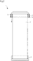
- Fig. 1 shows an embodiment of a filter cartridge (1) in which the second end of the protective cover (5) is in the first position and the filter material (2) forming the hollow cylinder is therefore not covered by the protective cover (5).
- One end of the protective cover (5) is attached to the first closing element (3) and the second end of the protective cover (5) is with the fastening element (6) releasably attached to the first closing element (3).
- the fastening element (6) After loosening the fastening element (6) it is possible to move the second end of the protective cover together with the fastening element (6) in the direction of the second closing element (4), the previously gathered protective cover (5) moving. spreads and covers the dirt side of the filter material (2).
- the fastening element (6) can then be fastened to the second closing element (4).
- Fig. 2 shows a cross section of a filter cartridge (1) in which the second end of the protective cover is in the first position.
- the first end of the protective covering (5) is fastened to the first closing element (3) and the second end to the fastening element (6), the first end of the protective covering (5) being between the first closing element (3) and the filter material ( 2) is clamped.
- the fastening element (6) is shown here as an example of a clamping ring.
- the fastening element (6) also represents a weight element which pulls the second end of the protective cover towards the second closing element (4) after the fastening means (6) have been loosened.
- the first and second closing elements (3, 4) surround the filter material (2) circumferentially and protrude radially beyond the hollow cylinder, both closing elements (3, 4) being shown here as foam rings by way of example.
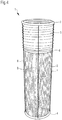
- Fig. 3 shows an embodiment of a filter cartridge in which the second end of the protective covering (5) is in the second position.
- the fastening element (6) is fastened to the second closing element (4) so that the dirt side of the hollow filter material cylinder is covered by the protective covering (5).
- Fig. 4 shows an embodiment of a filter cartridge (1) in which the second end of the protective cover (5) is in the first position.
- the second end of the protective cover (5) is attached to three guide rails (7, 8, 9) running parallel to the longitudinal axis of the hollow cylinder formed by the filter material (2) and guided by them can be moved from the first position to the second position will.
- the guide rails (7, 8, 9) run from the first closing element (3) to the second closing element (4) and are arranged outside the hollow cylinder and at a distance from it.
Landscapes
- Chemical & Material Sciences (AREA)
- Chemical Kinetics & Catalysis (AREA)
- Health & Medical Sciences (AREA)
- Engineering & Computer Science (AREA)
- Environmental & Geological Engineering (AREA)
- Toxicology (AREA)
- Physics & Mathematics (AREA)
- Geometry (AREA)
- Filtering Of Dispersed Particles In Gases (AREA)
Priority Applications (1)
| Application Number | Priority Date | Filing Date | Title |
|---|---|---|---|
| PL19184947T PL3593886T3 (pl) | 2018-07-13 | 2019-07-08 | Wkład filtra wymienialny bez zanieczyszczeń |
Applications Claiming Priority (1)
| Application Number | Priority Date | Filing Date | Title |
|---|---|---|---|
| DE102018117050.5A DE102018117050A1 (de) | 2018-07-13 | 2018-07-13 | Kontaminationsfrei wechselbare Filterpatrone |
Publications (2)
| Publication Number | Publication Date |
|---|---|
| EP3593886A1 EP3593886A1 (de) | 2020-01-15 |
| EP3593886B1 true EP3593886B1 (de) | 2021-09-22 |
Family
ID=67211596
Family Applications (1)
| Application Number | Title | Priority Date | Filing Date |
|---|---|---|---|
| EP19184947.0A Active EP3593886B1 (de) | 2018-07-13 | 2019-07-08 | Kontaminationsfrei wechselbare filterpatrone |
Country Status (4)
| Country | Link |
|---|---|
| EP (1) | EP3593886B1 (pl) |
| DE (1) | DE102018117050A1 (pl) |
| ES (1) | ES2898399T3 (pl) |
| PL (1) | PL3593886T3 (pl) |
Families Citing this family (2)
| Publication number | Priority date | Publication date | Assignee | Title |
|---|---|---|---|---|
| EP4454734B1 (en) * | 2019-06-27 | 2026-02-04 | Donaldson Company, Inc. | Filter assembly and system |
| CN118022415B (zh) * | 2024-03-26 | 2024-10-22 | 珂睿斯科技(深圳)有限公司 | 一种防溢式滤芯及净水器 |
Family Cites Families (8)
| Publication number | Priority date | Publication date | Assignee | Title |
|---|---|---|---|---|
| SE400478B (sv) * | 1975-01-13 | 1978-04-03 | Svenska Flaektfabriken Ab | Anordning for avlegsnande respektive tomning eller inspektion av filter, serskilt slangfilter |
| US4882051A (en) * | 1986-05-26 | 1989-11-21 | Nippon Roki Co., Ltd. | Cartridge filter incorporating a bag-like body |
| DE4216343C2 (de) * | 1992-05-16 | 2001-04-19 | Bayerische Motoren Werke Ag | Verfahren und Vorrichtung zum Ausbau eines Fahrzeug-Klimatisierungsfilters |
| FR2781550B1 (fr) * | 1998-07-27 | 2000-10-06 | Soc Et Et De Const Aero Navale | Procede de changement d'une cartouche filtrante montee dans un conduit d'ecoulement d'un fluide et agencement pour la mise en oeuvre du procede |
| DE19930614A1 (de) * | 1999-07-02 | 2001-01-04 | Mann & Hummel Filter | Filtereinsatz |
| US20070221585A1 (en) * | 2006-02-10 | 2007-09-27 | Vozar Andrea L | Collapsible Protective Cover for a Filter |
| DE102014114592A1 (de) * | 2014-10-08 | 2016-04-14 | Schuko Heinz Schulte-Südhoff GmbH & Co. KG | Filterpatrone zur Reinigung von Luft |
| DE102015105059B4 (de) * | 2015-04-01 | 2019-06-27 | Vorwerk & Co. Interholding Gmbh | Filteranordnung, Haushaltsgerät mit einer Filteranordnung und Verfahren zum Wechseln eines Filters |
-
2018
- 2018-07-13 DE DE102018117050.5A patent/DE102018117050A1/de not_active Ceased
-
2019
- 2019-07-08 PL PL19184947T patent/PL3593886T3/pl unknown
- 2019-07-08 ES ES19184947T patent/ES2898399T3/es active Active
- 2019-07-08 EP EP19184947.0A patent/EP3593886B1/de active Active
Also Published As
| Publication number | Publication date |
|---|---|
| PL3593886T3 (pl) | 2022-02-07 |
| ES2898399T3 (es) | 2022-03-07 |
| EP3593886A1 (de) | 2020-01-15 |
| DE102018117050A1 (de) | 2020-01-16 |
Similar Documents
| Publication | Publication Date | Title |
|---|---|---|
| EP0695572B1 (de) | Ölabscheider | |
| DE69218697T2 (de) | Integrierter Gusskragen, Filtersack, Käfig und Sperringanordnung für Sachhäuser | |
| DE59610237C5 (de) | Einrichtung zum Entstauben von Gas | |
| DE19747337A1 (de) | Siebsystem | |
| DE2846454A1 (de) | Filterhalter zur befestigung eines filterbeutels in einem filtersystem | |
| DE102016001485B4 (de) | Filtermodul und Gehäuse mit einem darin angeordneten Filtermodul | |
| DE102015105059B4 (de) | Filteranordnung, Haushaltsgerät mit einer Filteranordnung und Verfahren zum Wechseln eines Filters | |
| DE102016001486B4 (de) | Vorrichtung zum Filtrieren von verunreinigter Luft und Filtermodul zur Verwendung in einer solchen Vorrichtung | |
| DE202020105243U1 (de) | Luftfiltersysteme, Filterschlauchanordnungen, Filterschläuche | |
| DE102015016446A1 (de) | Schutzfiltervorrichtung, Innenraumluftfiltersystem sowie Verfahren zur Reinigung von mit Schadgasen und/oder Aerosolen und/oder Feststoffpartikelstaub beladener Luft | |
| EP3593886B1 (de) | Kontaminationsfrei wechselbare filterpatrone | |
| DE102008026068A1 (de) | Drei-Dichtungs-Anordnung mit ziehender Druckfeder seitlich neben der Filterzelle | |
| DE69012495T2 (de) | Schlauchfilterapparat. | |
| DE202007003135U1 (de) | Nachfüllbare Filterkartusche | |
| EP1034830B1 (de) | Vorrichtung zur Filtration eines mit Aerosolen beladenen Gasstromes | |
| EP1543872B1 (de) | Filtervorrichtung mit einem Filterschlauch und einer Reinigungseinrichtung für den Filterschlauch | |
| DE202018006399U1 (de) | Kontaminationsfrei wechselbare Filterpatrone | |
| DE9318673U1 (de) | Hohlzylindrisches Filterelement und damit hergestellte Filtereinheit | |
| DE202009013103U1 (de) | Zylindrische Filterpatrone für eine Filtervorrichtung zum Entfernen von Feinstäuben aus einem staubbeladenen Gasstrom sowie Filtervorrichtung und Filteranlage mit selbiger | |
| EP1911503A2 (de) | Filtereinrichtung, insbesondere zur Filtration von Verbrennungsluft in Brennkraftmaschinen | |
| EP4216786B1 (de) | Filtereinrichtung für einen staubsauger und filterabreinigungsverfahren | |
| EP0699465A2 (de) | Luftfilter | |
| EP3763431B1 (de) | Filtergerät | |
| EP4438158A1 (de) | Luftfilteranordnung sowie verfahren zum auswechseln mehrerer filterelemente | |
| DE29808779U1 (de) | Filtergerät |
Legal Events
| Date | Code | Title | Description |
|---|---|---|---|
| PUAI | Public reference made under article 153(3) epc to a published international application that has entered the european phase |
Free format text: ORIGINAL CODE: 0009012 |
|
| STAA | Information on the status of an ep patent application or granted ep patent |
Free format text: STATUS: THE APPLICATION HAS BEEN PUBLISHED |
|
| AK | Designated contracting states |
Kind code of ref document: A1 Designated state(s): AL AT BE BG CH CY CZ DE DK EE ES FI FR GB GR HR HU IE IS IT LI LT LU LV MC MK MT NL NO PL PT RO RS SE SI SK SM TR |
|
| AX | Request for extension of the european patent |
Extension state: BA ME |
|
| STAA | Information on the status of an ep patent application or granted ep patent |
Free format text: STATUS: REQUEST FOR EXAMINATION WAS MADE |
|
| 17P | Request for examination filed |
Effective date: 20200706 |
|
| RBV | Designated contracting states (corrected) |
Designated state(s): AL AT BE BG CH CY CZ DE DK EE ES FI FR GB GR HR HU IE IS IT LI LT LU LV MC MK MT NL NO PL PT RO RS SE SI SK SM TR |
|
| STAA | Information on the status of an ep patent application or granted ep patent |
Free format text: STATUS: EXAMINATION IS IN PROGRESS |
|
| 17Q | First examination report despatched |
Effective date: 20201020 |
|
| GRAP | Despatch of communication of intention to grant a patent |
Free format text: ORIGINAL CODE: EPIDOSNIGR1 |
|
| STAA | Information on the status of an ep patent application or granted ep patent |
Free format text: STATUS: GRANT OF PATENT IS INTENDED |
|
| INTG | Intention to grant announced |
Effective date: 20210511 |
|
| GRAS | Grant fee paid |
Free format text: ORIGINAL CODE: EPIDOSNIGR3 |
|
| GRAA | (expected) grant |
Free format text: ORIGINAL CODE: 0009210 |
|
| STAA | Information on the status of an ep patent application or granted ep patent |
Free format text: STATUS: THE PATENT HAS BEEN GRANTED |
|
| AK | Designated contracting states |
Kind code of ref document: B1 Designated state(s): AL AT BE BG CH CY CZ DE DK EE ES FI FR GB GR HR HU IE IS IT LI LT LU LV MC MK MT NL NO PL PT RO RS SE SI SK SM TR |
|
| REG | Reference to a national code |
Ref country code: GB Ref legal event code: FG4D Free format text: NOT ENGLISH |
|
| REG | Reference to a national code |
Ref country code: IE Ref legal event code: FG4D Free format text: LANGUAGE OF EP DOCUMENT: GERMAN |
|
| REG | Reference to a national code |
Ref country code: DE Ref legal event code: R096 Ref document number: 502019002325 Country of ref document: DE |
|
| REG | Reference to a national code |
Ref country code: CH Ref legal event code: EP Ref country code: AT Ref legal event code: REF Ref document number: 1431864 Country of ref document: AT Kind code of ref document: T Effective date: 20211015 |
|
| REG | Reference to a national code |
Ref country code: DE Ref legal event code: R082 Ref document number: 502019002325 Country of ref document: DE Representative=s name: DEMSKI & NOBBE PATENTANWAELTE, DE Ref country code: DE Ref legal event code: R082 Ref document number: 502019002325 Country of ref document: DE Representative=s name: SEYER & NOBBE PATENTANWAELTE PARTNERSCHAFTSGES, DE |
|
| REG | Reference to a national code |
Ref country code: DK Ref legal event code: T3 Effective date: 20211124 |
|
| REG | Reference to a national code |
Ref country code: SE Ref legal event code: TRGR |
|
| REG | Reference to a national code |
Ref country code: NL Ref legal event code: FP |
|
| REG | Reference to a national code |
Ref country code: LT Ref legal event code: MG9D |
|
| PG25 | Lapsed in a contracting state [announced via postgrant information from national office to epo] |
Ref country code: HR Free format text: LAPSE BECAUSE OF FAILURE TO SUBMIT A TRANSLATION OF THE DESCRIPTION OR TO PAY THE FEE WITHIN THE PRESCRIBED TIME-LIMIT Effective date: 20210922 Ref country code: NO Free format text: LAPSE BECAUSE OF FAILURE TO SUBMIT A TRANSLATION OF THE DESCRIPTION OR TO PAY THE FEE WITHIN THE PRESCRIBED TIME-LIMIT Effective date: 20211222 Ref country code: LT Free format text: LAPSE BECAUSE OF FAILURE TO SUBMIT A TRANSLATION OF THE DESCRIPTION OR TO PAY THE FEE WITHIN THE PRESCRIBED TIME-LIMIT Effective date: 20210922 Ref country code: BG Free format text: LAPSE BECAUSE OF FAILURE TO SUBMIT A TRANSLATION OF THE DESCRIPTION OR TO PAY THE FEE WITHIN THE PRESCRIBED TIME-LIMIT Effective date: 20211222 Ref country code: RS Free format text: LAPSE BECAUSE OF FAILURE TO SUBMIT A TRANSLATION OF THE DESCRIPTION OR TO PAY THE FEE WITHIN THE PRESCRIBED TIME-LIMIT Effective date: 20210922 Ref country code: FI Free format text: LAPSE BECAUSE OF FAILURE TO SUBMIT A TRANSLATION OF THE DESCRIPTION OR TO PAY THE FEE WITHIN THE PRESCRIBED TIME-LIMIT Effective date: 20210922 |
|
| PG25 | Lapsed in a contracting state [announced via postgrant information from national office to epo] |
Ref country code: LV Free format text: LAPSE BECAUSE OF FAILURE TO SUBMIT A TRANSLATION OF THE DESCRIPTION OR TO PAY THE FEE WITHIN THE PRESCRIBED TIME-LIMIT Effective date: 20210922 Ref country code: GR Free format text: LAPSE BECAUSE OF FAILURE TO SUBMIT A TRANSLATION OF THE DESCRIPTION OR TO PAY THE FEE WITHIN THE PRESCRIBED TIME-LIMIT Effective date: 20211223 |
|
| REG | Reference to a national code |
Ref country code: ES Ref legal event code: FG2A Ref document number: 2898399 Country of ref document: ES Kind code of ref document: T3 Effective date: 20220307 |
|
| PG25 | Lapsed in a contracting state [announced via postgrant information from national office to epo] |
Ref country code: IS Free format text: LAPSE BECAUSE OF FAILURE TO SUBMIT A TRANSLATION OF THE DESCRIPTION OR TO PAY THE FEE WITHIN THE PRESCRIBED TIME-LIMIT Effective date: 20220122 Ref country code: SK Free format text: LAPSE BECAUSE OF FAILURE TO SUBMIT A TRANSLATION OF THE DESCRIPTION OR TO PAY THE FEE WITHIN THE PRESCRIBED TIME-LIMIT Effective date: 20210922 Ref country code: RO Free format text: LAPSE BECAUSE OF FAILURE TO SUBMIT A TRANSLATION OF THE DESCRIPTION OR TO PAY THE FEE WITHIN THE PRESCRIBED TIME-LIMIT Effective date: 20210922 Ref country code: PT Free format text: LAPSE BECAUSE OF FAILURE TO SUBMIT A TRANSLATION OF THE DESCRIPTION OR TO PAY THE FEE WITHIN THE PRESCRIBED TIME-LIMIT Effective date: 20220124 Ref country code: EE Free format text: LAPSE BECAUSE OF FAILURE TO SUBMIT A TRANSLATION OF THE DESCRIPTION OR TO PAY THE FEE WITHIN THE PRESCRIBED TIME-LIMIT Effective date: 20210922 Ref country code: AL Free format text: LAPSE BECAUSE OF FAILURE TO SUBMIT A TRANSLATION OF THE DESCRIPTION OR TO PAY THE FEE WITHIN THE PRESCRIBED TIME-LIMIT Effective date: 20210922 |
|
| REG | Reference to a national code |
Ref country code: DE Ref legal event code: R097 Ref document number: 502019002325 Country of ref document: DE |
|
| PLBE | No opposition filed within time limit |
Free format text: ORIGINAL CODE: 0009261 |
|
| STAA | Information on the status of an ep patent application or granted ep patent |
Free format text: STATUS: NO OPPOSITION FILED WITHIN TIME LIMIT |
|
| 26N | No opposition filed |
Effective date: 20220623 |
|
| PG25 | Lapsed in a contracting state [announced via postgrant information from national office to epo] |
Ref country code: SI Free format text: LAPSE BECAUSE OF FAILURE TO SUBMIT A TRANSLATION OF THE DESCRIPTION OR TO PAY THE FEE WITHIN THE PRESCRIBED TIME-LIMIT Effective date: 20210922 |
|
| PG25 | Lapsed in a contracting state [announced via postgrant information from national office to epo] |
Ref country code: MC Free format text: LAPSE BECAUSE OF FAILURE TO SUBMIT A TRANSLATION OF THE DESCRIPTION OR TO PAY THE FEE WITHIN THE PRESCRIBED TIME-LIMIT Effective date: 20210922 |
|
| P01 | Opt-out of the competence of the unified patent court (upc) registered |
Effective date: 20230523 |
|
| PG25 | Lapsed in a contracting state [announced via postgrant information from national office to epo] |
Ref country code: IE Free format text: LAPSE BECAUSE OF NON-PAYMENT OF DUE FEES Effective date: 20220708 |
|
| PGFP | Annual fee paid to national office [announced via postgrant information from national office to epo] |
Ref country code: LU Payment date: 20230719 Year of fee payment: 5 |
|
| PGFP | Annual fee paid to national office [announced via postgrant information from national office to epo] |
Ref country code: CH Payment date: 20230801 Year of fee payment: 5 |
|
| REG | Reference to a national code |
Ref country code: DE Ref legal event code: R082 Ref document number: 502019002325 Country of ref document: DE Representative=s name: SEYER & NOBBE PATENTANWAELTE PARTNERSCHAFTSGES, DE |
|
| PG25 | Lapsed in a contracting state [announced via postgrant information from national office to epo] |
Ref country code: HU Free format text: LAPSE BECAUSE OF FAILURE TO SUBMIT A TRANSLATION OF THE DESCRIPTION OR TO PAY THE FEE WITHIN THE PRESCRIBED TIME-LIMIT; INVALID AB INITIO Effective date: 20190708 |
|
| PG25 | Lapsed in a contracting state [announced via postgrant information from national office to epo] |
Ref country code: SM Free format text: LAPSE BECAUSE OF FAILURE TO SUBMIT A TRANSLATION OF THE DESCRIPTION OR TO PAY THE FEE WITHIN THE PRESCRIBED TIME-LIMIT Effective date: 20210922 Ref country code: MK Free format text: LAPSE BECAUSE OF FAILURE TO SUBMIT A TRANSLATION OF THE DESCRIPTION OR TO PAY THE FEE WITHIN THE PRESCRIBED TIME-LIMIT Effective date: 20210922 Ref country code: CY Free format text: LAPSE BECAUSE OF FAILURE TO SUBMIT A TRANSLATION OF THE DESCRIPTION OR TO PAY THE FEE WITHIN THE PRESCRIBED TIME-LIMIT Effective date: 20210922 |
|
| PGFP | Annual fee paid to national office [announced via postgrant information from national office to epo] |
Ref country code: CZ Payment date: 20240625 Year of fee payment: 6 |
|
| PGFP | Annual fee paid to national office [announced via postgrant information from national office to epo] |
Ref country code: PL Payment date: 20240628 Year of fee payment: 6 |
|
| PGFP | Annual fee paid to national office [announced via postgrant information from national office to epo] |
Ref country code: NL Payment date: 20240722 Year of fee payment: 6 |
|
| PG25 | Lapsed in a contracting state [announced via postgrant information from national office to epo] |
Ref country code: MT Free format text: LAPSE BECAUSE OF FAILURE TO SUBMIT A TRANSLATION OF THE DESCRIPTION OR TO PAY THE FEE WITHIN THE PRESCRIBED TIME-LIMIT Effective date: 20210922 |
|
| PGFP | Annual fee paid to national office [announced via postgrant information from national office to epo] |
Ref country code: DE Payment date: 20240719 Year of fee payment: 6 |
|
| PGFP | Annual fee paid to national office [announced via postgrant information from national office to epo] |
Ref country code: DK Payment date: 20240722 Year of fee payment: 6 |
|
| PGFP | Annual fee paid to national office [announced via postgrant information from national office to epo] |
Ref country code: GB Payment date: 20240723 Year of fee payment: 6 |
|
| PGFP | Annual fee paid to national office [announced via postgrant information from national office to epo] |
Ref country code: BE Payment date: 20240722 Year of fee payment: 6 |
|
| PGFP | Annual fee paid to national office [announced via postgrant information from national office to epo] |
Ref country code: FR Payment date: 20240724 Year of fee payment: 6 |
|
| PGFP | Annual fee paid to national office [announced via postgrant information from national office to epo] |
Ref country code: ES Payment date: 20240816 Year of fee payment: 6 |
|
| PGFP | Annual fee paid to national office [announced via postgrant information from national office to epo] |
Ref country code: AT Payment date: 20240718 Year of fee payment: 6 |
|
| PGFP | Annual fee paid to national office [announced via postgrant information from national office to epo] |
Ref country code: SE Payment date: 20240722 Year of fee payment: 6 Ref country code: IT Payment date: 20240731 Year of fee payment: 6 |
|
| REG | Reference to a national code |
Ref country code: CH Ref legal event code: PL |
|
| PG25 | Lapsed in a contracting state [announced via postgrant information from national office to epo] |
Ref country code: LU Free format text: LAPSE BECAUSE OF NON-PAYMENT OF DUE FEES Effective date: 20240708 |
|
| PG25 | Lapsed in a contracting state [announced via postgrant information from national office to epo] |
Ref country code: LU Free format text: LAPSE BECAUSE OF NON-PAYMENT OF DUE FEES Effective date: 20240708 |
|
| PG25 | Lapsed in a contracting state [announced via postgrant information from national office to epo] |
Ref country code: CH Free format text: LAPSE BECAUSE OF NON-PAYMENT OF DUE FEES Effective date: 20240731 |
|
| PG25 | Lapsed in a contracting state [announced via postgrant information from national office to epo] |
Ref country code: TR Free format text: LAPSE BECAUSE OF FAILURE TO SUBMIT A TRANSLATION OF THE DESCRIPTION OR TO PAY THE FEE WITHIN THE PRESCRIBED TIME-LIMIT Effective date: 20210922 |
|
| PG25 | Lapsed in a contracting state [announced via postgrant information from national office to epo] |
Ref country code: CZ Free format text: LAPSE BECAUSE OF NON-PAYMENT OF DUE FEES Effective date: 20250708 |
|
| REG | Reference to a national code |
Ref country code: DE Ref legal event code: R119 Ref document number: 502019002325 Country of ref document: DE |
|
| REG | Reference to a national code |
Ref country code: DK Ref legal event code: EBP Effective date: 20250731 |
|
| REG | Reference to a national code |
Ref country code: NL Ref legal event code: MM Effective date: 20250801 |
|
| REG | Reference to a national code |
Ref country code: AT Ref legal event code: MM01 Ref document number: 1431864 Country of ref document: AT Kind code of ref document: T Effective date: 20250708 |
|
| GBPC | Gb: european patent ceased through non-payment of renewal fee |
Effective date: 20250708 |
|
| REG | Reference to a national code |
Ref country code: BE Ref legal event code: MM Effective date: 20250731 |
|
| PG25 | Lapsed in a contracting state [announced via postgrant information from national office to epo] |
Ref country code: GB Free format text: LAPSE BECAUSE OF NON-PAYMENT OF DUE FEES Effective date: 20250708 |
|
| PG25 | Lapsed in a contracting state [announced via postgrant information from national office to epo] |
Ref country code: DE Free format text: LAPSE BECAUSE OF NON-PAYMENT OF DUE FEES Effective date: 20260203 |
|
| PG25 | Lapsed in a contracting state [announced via postgrant information from national office to epo] |
Ref country code: AT Free format text: LAPSE BECAUSE OF NON-PAYMENT OF DUE FEES Effective date: 20250708 |
|
| PG25 | Lapsed in a contracting state [announced via postgrant information from national office to epo] |
Ref country code: BE Free format text: LAPSE BECAUSE OF NON-PAYMENT OF DUE FEES Effective date: 20250731 |
|
| PG25 | Lapsed in a contracting state [announced via postgrant information from national office to epo] |
Ref country code: NL Free format text: LAPSE BECAUSE OF NON-PAYMENT OF DUE FEES Effective date: 20250801 |
|
| PG25 | Lapsed in a contracting state [announced via postgrant information from national office to epo] |
Ref country code: FR Free format text: LAPSE BECAUSE OF NON-PAYMENT OF DUE FEES Effective date: 20250731 |