EP3593744B1 - Dichtungspatronenverriegelungsdesign für trokaranordnungen - Google Patents
Dichtungspatronenverriegelungsdesign für trokaranordnungen Download PDFInfo
- Publication number
- EP3593744B1 EP3593744B1 EP19186144.2A EP19186144A EP3593744B1 EP 3593744 B1 EP3593744 B1 EP 3593744B1 EP 19186144 A EP19186144 A EP 19186144A EP 3593744 B1 EP3593744 B1 EP 3593744B1
- Authority
- EP
- European Patent Office
- Prior art keywords
- trocar
- latch ring
- latches
- seal cartridge
- main body
- Prior art date
- Legal status (The legal status is an assumption and is not a legal conclusion. Google has not performed a legal analysis and makes no representation as to the accuracy of the status listed.)
- Active
Links
Images

Classifications
-
- A—HUMAN NECESSITIES
- A61—MEDICAL OR VETERINARY SCIENCE; HYGIENE
- A61B—DIAGNOSIS; SURGERY; IDENTIFICATION
- A61B17/00—Surgical instruments, devices or methods
- A61B17/34—Trocars; Puncturing needles
- A61B17/3462—Trocars; Puncturing needles with means for changing the diameter or the orientation of the entrance port of the cannula, e.g. for use with different-sized instruments, reduction ports, adapter seals
-
- A—HUMAN NECESSITIES
- A61—MEDICAL OR VETERINARY SCIENCE; HYGIENE
- A61B—DIAGNOSIS; SURGERY; IDENTIFICATION
- A61B17/00—Surgical instruments, devices or methods
- A61B17/02—Surgical instruments, devices or methods for holding wounds open, e.g. retractors; Tractors
- A61B17/0218—Surgical instruments, devices or methods for holding wounds open, e.g. retractors; Tractors for minimally invasive surgery
-
- A—HUMAN NECESSITIES
- A61—MEDICAL OR VETERINARY SCIENCE; HYGIENE
- A61B—DIAGNOSIS; SURGERY; IDENTIFICATION
- A61B17/00—Surgical instruments, devices or methods
- A61B17/34—Trocars; Puncturing needles
- A61B17/3417—Details of tips or shafts, e.g. grooves, expandable, bendable; Multiple coaxial sliding cannulas, e.g. for dilating
- A61B17/3421—Cannulas
- A61B17/3423—Access ports, e.g. toroid shape introducers for instruments or hands
-
- A—HUMAN NECESSITIES
- A61—MEDICAL OR VETERINARY SCIENCE; HYGIENE
- A61B—DIAGNOSIS; SURGERY; IDENTIFICATION
- A61B17/00—Surgical instruments, devices or methods
- A61B17/34—Trocars; Puncturing needles
- A61B17/3498—Valves therefor, e.g. flapper valves, slide valves
-
- A—HUMAN NECESSITIES
- A61—MEDICAL OR VETERINARY SCIENCE; HYGIENE
- A61B—DIAGNOSIS; SURGERY; IDENTIFICATION
- A61B17/00—Surgical instruments, devices or methods
- A61B2017/00477—Coupling
Definitions
- a trocar assembly is inserted through the incision to provide access to an internal body cavity, such as the patient's abdomen.
- the trocar assembly operates as a pathway that can be used to introduce various surgical instruments and tools into the abdomen.
- a trocar assembly generally includes a trocar and a seal assembly operatively coupled to or forming part of the trocar.
- the trocar includes a trocar housing and a cannula that extends distally from the trocar housing and provides the pathway into the patient's abdomen.
- the seal assembly includes one or more seals that help maintain insufflation of the penetrated body cavity and also seal about surgical tools extended through the trocar and into the patient's abdomen.
- the seal assembly may comprise a seal cartridge at least partially received within the trocar housing and releasably coupled thereto. Due to minimal space constraints, it is desired to releasably couple the seal cartridge to the trocar housing simply and efficiently.
- the seal cartridge may be allowed to rotate continuously and freely within the trocar housing once releasably coupled or may be allowed to rotate to discrete positions to allow for multiple orientations of the insufflation valve relative to the remainder of the trocar housing.
- US 5792113 describes a universal seal for a trocar.
- the seal is a multi-component assembly that, when assembled, has a rigid housing with a sealing assembly inside the housing.
- the housing has top and bottom faces. Each of the faces has an opening through it to create a pathway through the universal seal.
- the top face includes a pair of spring-biased latches for coupling the universal seal to the trocar cannula.
- the bottom face of the rigid housing has a tubular neck to facilitate the guidance of instruments inserted through the seal into the trocar cannula.
- the sealing assembly includes an inner conical seal and an outer seal.
- the inner seal is designed to seal against instruments of varying diameter.
- the outer seal is shaped in the form of a doughnut.
- the doughnut hole of the outer seal corresponds in size to the size of the pathway located through the top and bottom faces of the rigid housing of the universal seal to enable the unrestricted passage of the largest diameter instruments through it.
- the sealing portion of the doughnut-shaped outer seal is composed of a material which is sufficiently compliant to provide for longitudinal movement of the outer seal despite the fact that it is secured along its circumferential edge to the rigid housing.
- the top face is then fixedly attached by ordinary means to the bottom face so that a mating surface on the housing top face sandwiches the circumferential edge of the outer seal between the mating surface and the seating surface of the housing bottom face.
- the universal seal is mounted to the housing of the trocar cannula when the latches on the housing top surface are forced inwardly, and received within vestibules of the trocar cannula. Once inward pressure on the latches is removed, the spring force of the latches applied against the inner walls of the vestibule secures the universal seal to the cannula housing.
- EP3020347 describes a surgical access attachment that includes an access port assembly and a ring.
- the access portion assembly includes a proximal seal retaining portion, a distal seal retaining portion, and a seal.
- the proximal seal retaining portion and the distal seal retaining portion are configured to mechanically engage each other (e.g., via snap-fit engagement) to house the seal.
- the ring is configured to selectively mechanically engage a proximal portion of the surgical access device.
- the access portion assembly which includes the proximal seal retaining portion, the distal seal retaining portion and the seal, is configured to engage a surgical access device by releasably engaging a ring, which is engaged with the surgical access device.
- the proximal seal retaining portion includes a rim, a plurality of fingers, and a flexible tab.
- the rim includes a generally L-shaped cross-section, a radially outer surface, and a radially inner surface.
- Each finger of the plurality of fingers depends distally from a distal surface of the rim.
- a portion of each finger of the plurality of fingers is configured to mechanically engage a portion of the distal seal retaining portion, discussed in greater detail below.
- the flexible tab extends radially outward from the rim, and includes a proximal portion, a leg, an engagement portion, and a living hinge. The living hinge interconnects the proximal portion and the leg, and enables the leg to flex with respect to the proximal portion.
- the engagement portion extends radially outward from the leg and is configured for engagement by a user to facilitate the flexing of the leg with respect to the proximal portion.
- the leg includes an engagement structure on its distal end, which is configured to mechanically engage a portion of the ring.
- Each finger of the plurality of fingers is configured to engage one engagement aperture of a plurality of engagement apertures in the distal seal retaining portion. More particularly, a body of each finger is configured to engage a first portion of an engagement aperture, and a lip of each finger is configured to engage a second portion of the engagement aperture.
- each finger is flexible such that lip is able to move into and out of engagement with a wall defining the second portion of the engagement aperture to facilitate engagement between the finger and the engagement aperture.
- Each finger and each engagement aperture can be disengaged from one another by moving the lip radially inward with respect to the engagement aperture. More particularly, it is envisioned that a tool can be inserted through the second portion of the engagement aperture, into contact with the lip of the finger to move the lip radially inward of the wall, thus enabling proximal movement of the proximal seal retaining portion.
- the present invention provides a seal cartridge comprising a frame that houses one or more seals, and a top cap adapted to be coupled to the frame and that includes a main body and a latch ring.
- the latch ring has a first and second latches, wherein the latches extend distally from the latch ring and are configured to releasably couple the seal cartridge to a trocar.
- the latch ring is grounded to the main body at two first angular positions located angularly opposite each other around the circumference of the latch ring and the first and second latches are located at angularly opposite second angular positions around the circumference of the latch ring, wherein the second positions angularly interpose the first positions, such that applying a radial load on the first and second latches simultaneously in opposite radial directions causes the latch ring to flex in torsion at intermediate portions that angularly interpose the first and second angular positions, and the latches to rotate radially inward relative to the main body.
- FIG. 1 is an isometric view of an example trocar assembly 100.
- the trocar assembly 100 includes a trocar 102 and a seal cartridge 104 that may be releasably coupled to the trocar 102.
- the trocar 102 includes a trocar housing 106 and a cannula 108 that extends distally from the trocar housing 106.
- the cannula 108 may comprise an integral extension of the trocar housing 106.
- the trocar housing 106 and the cannula 108 may comprise two separate components that are permanently or semi-permanently mated to one another.
- the trocar 102 may be made of any rigid or semi-rigid material, such as a metal or a plastic.
- the seal cartridge 104 is at least partially received within the trocar housing 106 and includes actuatable latches 110 (one shown and one hidden) that releasably couple the seal cartridge 104 to the trocar 102.
- the seal cartridge 104 includes two latches 110 (alternately referred to as "touchpoints") that are positioned radially (angularly) opposite each other about the circumference (outer periphery) of the seal cartridge 104. In other embodiments, more than two latches 110 may be employed.
- the latches 110 may be equidistantly or non-equidistantly spaced from each other.
- the trocar assembly 100 may also include an insufflation valve 112 (e.g., a stopcock valve) operable to regulate the influx of an insufflation fluid (e.g. carbon dioxide) used to elevate the interior walls of an inner body cavity (e.g., the abdomen) of a patient.
- an insufflation valve 112 e.g., a stopcock valve
- the insufflation valve 112 is coupled to the seal cartridge 104 or otherwise forms an integral part thereof.
- the insufflation valve 112 may alternatively be coupled to the trocar housing 106 or may form an integral part thereof.
- the trocar 102 may further include a lug 114 that extends radially outward from the trocar housing 106.
- the robot (not shown) may be configured to latch onto the lug 114 to enable accurate insertion of surgical tools into the trocar assembly 100.
- the lug 114 may be omitted.
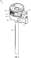
- FIG. 2 is a partial exploded view of the trocar assembly 100 of FIG. 1 . More particularly, the seal cartridge 104 is shown exploded from the trocar 102. To releasably couple the seal cartridge 104 to the trocar 102, the seal cartridge 104 may be introduced at least partially into the trocar housing 106 until the latches 110 (one shown) of the seal cartridge 104 engage and mate with the inner circumferential surface of the trocar housing 106. More specifically, each latch 110 may provide or otherwise define an outer lip 202 configured to mate with an opposing inner lip 204 defined on the inner circumferential surface of the trocar housing 106.
- the outer lip 202 and the inner lip 204 may be oppositely angled and thereby complement one another to urge the latches 110 to flex radially inward as the outer lip 202 engages the inner lip 204 in the distal direction.
- the latches 110 are able to flex radially outward and opposing flat surfaces of the outer lip 202 and the inner lip 204 engage to help secure and maintain the seal cartridge 104 within the trocar housing 106.
- the latches 110 may be flexed radially inward to disengage the opposing flat surfaces and thereby enable to the outer lip 202 to bypass the inner lip 204 as the seal cartridge 104 is moved proximally.
- the inner lip 204 may extend about the entire inner circumference of the trocar housing 106. Consequently, the seal cartridge 104 may be releasably coupled to the trocar housing 106 by mating the outer lip 202 and the inner lip 204 at virtually any angular direction.
- the trocar assembly 100 may include an anti-rotation mechanism that helps prevent the seal cartridge 104 from rotating relative to the trocar housing 106 once properly received therein. More particularly, as illustrated, one or more protrusions 206 or "teeth" may be defined on the outer lip 202, and one or more indentations 208 may be defined on the inner lip 204. In the illustrated embodiment, a plurality of protrusions 206 and indentations 208 are defined in the outer lip 202 and the inner lip 204. Embodiments are contemplated herein, however, wherein the outer lip 202 provides only one protrusion 206 and the inner lip 204 provides only one indentation 208. In such embodiments, the seal cartridge 104 may be rotationally secured relative to the trocar 102 in a single angular orientation.
- the relative spacing of the protrusions 206 may match the relative spacing of the indentations 208 such that when the seal cartridge 104 is received within the trocar housing 106 and the outer lip 202 mates with the inner lip 204, as generally described above, the protrusions 206 may be able to angularly align with and be received within the indentations 208. Receiving the protrusions 206 within the indentations 208 may help restrain the seal cartridge 104 in a particular, discrete angular orientation.
- a load e.g., a radial load
- the seal cartridge 104 may then be rotated in either angular direction (i.e., clockwise or counter-clockwise) and the protrusions 206 will bypass the radially opposing indentations 208 until a desired angular orientation is achieved, at which point the load on the latches 110 may be released to allow the protrusions 206 to mate with opposing indentations 208 in the new angular orientation.
- the latches 110 may be dual-purpose; to hold the seal cartridge 104 within the trocar housing 106, and to prevent rotation of the seal cartridge 104 relative to the trocar 102.
- the indentations 208 are defined about the entire inner circumference of the trocar housing 106 and equidistantly spaced from each other. In other embodiments, however, the indentations 208 may extend only partially about the inner circumference. In yet other embodiments, the indentations 208 may be defined in groups (clusters of indentations 208) arranged at predetermined intervals about the inner circumference of the trocar housing 106. In such embodiments, the groups of indentations may be equidistantly or non-equidistantly spaced from each other.
- the protrusions 206 being defined on the latches 110 and the indentations 208 defined on the inner surface of the trocar housing 106
- an opposite configuration is contemplated herein. More specifically, in another embodiment, the protrusions 206 may be defined on the inner surface of the trocar housing 106 and the indentations 208 may be defined on the latches 110.
- operation of the seal cartridge 104 with respect to the trocar 102 may be the same as generally described above.
- protrusions 206 and the indentations 208 are elongated features that extend longitudinally and generally parallel to the centerline of the trocar assembly 100
- protrusions 206 and indentations 208 may comprise circular or spherical buttons and the indentations 208 may define corresponding circular or spherical cavities sized to receive the buttons.
- the mating protrusions 206 and indentations 208 may be employed.
- the defined edges of one or both of the protrusions 206 and the indentations 208 may be angled or rounded.
- the seal cartridge 104 may be able to "ratchet" in the angular direction as the protrusions 206 successively engage and disengage the angularly adjacent indentations 208. Having angled or rounded edges may prove advantageous in helping to facilitate easy disengagement and reengagement of the protrusions 206 with the indentations 208 during rotational movement.
- the rotational force that moves the seal cartridge 104 relative to the trocar 102 may provide sufficient force to urge the protrusions 206 to flex radially in and out of engagement with successive and radially adjacent indentations 208.
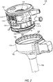
- the seal cartridge 104 includes two or more component parts. More particularly, the seal cartridge 104 includes a frame 210 and a top cap 212.
- the frame 210 is configured to house and seat one or more seals (not shown) used to help maintain insufflation and seal about surgical tools extended longitudinally through the trocar assembly 100.
- the frame 210 may also include an external seal 214 that provides a sealed interface against the inside of the trocar 102 when the seal cartridge 104 is received within the trocar housing 106.
- the top cap 212 may provide or otherwise define a central opening 216 that provides access into the seal cartridge 104. Surgical tools to be used in an operation may be introduced into the trocar assembly 100 via the central opening 216 and extended distally through the cannula 108.
- the top cap 212 may be releasably coupled to the frame 210.
- the top cap 212 may be secured to the frame 210 using a mechanical coupling, such as one or more press pins and corresponding pin cavities, one or more barbed latches and corresponding latch cavities, an interference fit, or any combination thereof.
- the top cap 212 may be secured to the frame 210 using one or more mechanical fasteners, such as screws or rivets.
- the top cap 212 may be permanently coupled to the frame 210, such as through the use of an adhesive or via a welding operation that permanently joins the top cap 212 to the frame 210.
- Example welding technologies that may be employed include, but are not limited to, ultrasonic, heated tool, or any combination thereof.
- the top cap 212 may be permanently coupled to the frame 210 via an infrared laser welding operation.
- the frame 210 may be made of a material that is transparent or translucent to the wavelength of the infrared source and thereby allows the electromagnetic radiation of the infrared source to transmit through the frame 210 material with little or no dissipation.
- the top cap 212 may be made of a material that is opaque to and otherwise absorbs the infrared energy at the wavelength of the infrared source, and thereby absorbs or partially absorbs the electromagnetic radiation of the infrared source.
- the frame 210 and the top cap 212 may be positioned in intimate contact with each other.
- a pulsed or continuous laser beam may be directed through a portion of the frame 210 that interfaces an opposing portion of the top cap 212, as indicated by the arrow A.
- the laser beam A is shown directed through a radial lip or protrusion 218 defined on the frame 210, and the radial protrusion 218 interfaces with a bottom portion 220 of the top cap 212.
- the laser beam A may be directed through other portions of the frame 210 that interface other opposing portions of the top cap 212.
- the electromagnetic radiation of the laser transmits through the radial protrusion 218 with little or no dissipation, but is absorbed by the opposing material of the top cap 212 after transmitting through the frame 210 material. Absorbing the electromagnetic radiation with the top cap 212 material dramatically increases the temperature at the interface of the top cap 212 and the frame 210 at that location, which heats both components by thermal conduction and results in a welded interface between the two parts once cooled. This process may be repeated multiple times at various locations about the circumference of the seal cartridge 104 to secure the top cap 212 to the frame 210.
- Suitable materials for the frame 210 that are transparent or translucent to the wavelength of the laser include, but are not limited to, any thermoplastic or thermoplastic composite that partially transmits infrared energy, and any combination thereof.
- the material for the frame 210 may be visibly clear, such that visible electromagnetic radiation (e.g., natural or artificial light) may pass therethrough relatively unobstructed. In other embodiments, however, the material for the frame 210 may be not be visibly clear, but instead only clear to the wavelength of the laser beam A.
- Suitable materials for the top cap 212 that are generally opaque to the wavelength of the laser include, but are not limited to, any thermoplastic or thermoplastic composite that fully or partially absorbs infrared energy. Additives or coatings can be utilized to enhance the absorption properties of the material, if desired.
- the frame 210 is described above as being made of a material that is transparent or translucent to the wavelength of the infrared source, and the top cap 212 is described as being made of a material that is opaque to and otherwise absorbs the infrared energy at the wavelength of the infrared source, it is contemplated herein to swap and still achieve the same results.
- the top cap 212 may be made of the material that is transparent or translucent to the wavelength of the infrared source
- the frame 210 may be made of the material that is opaque to and otherwise absorbs the infrared energy at the wavelength of the infrared source.
- the seal cartridge 104 may further include a seal retainer 222 coupled to a distal end of the frame 210. Similar to the coupled engagement between the top cap 212 and the frame 210, in some embodiments, the seal retainer 222 may be releasably coupled to the frame 210, such as by using a mechanical coupling or with one or more mechanical fasteners, as discussed herein. The seal retainer 222 may alternatively be permanently coupled to the frame 210, such as through the use of an adhesive, ultrasonic welding, or laser welding.
- the frame 210 may be made of any of the materials mentioned herein that are transparent or translucent to the wavelength of a laser, and the seal retainer 222 may be made of any of the materials mentioned herein that are opaque to the wavelength of the laser.
- a pulsed or continuous laser beam may be directed through a portion of the frame 210 that interfaces the seal retainer 222, as indicated by the arrow B.
- the electromagnetic radiation of the laser B penetrates the frame 210 material with little or no dissipation, but is absorbed by the seal retainer 222 material and causes one or both of the materials to melt and provide a welded interface upon cooling. This process may be repeated multiple times at various locations about the circumference of the seal retainer 222 to secure the seal retainer 222 to the frame 210.
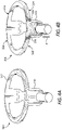
- FIGS. 3A and 3B are enlarged isometric and exploded views, respectively, of the top cap 212, according to one or more embodiments.
- the top cap 212 includes two or more component parts. More particularly, the top cap 212 comprises a main body 302 (alternately referred to as an "upper seal retainer") and a latch ring 304 that is mounted to the main body 302.
- a main body 302 alternatively referred to as an "upper seal retainer”
- latch ring 304 that is mounted to the main body 302.
- the main body 302 may comprise a generally cylindrical structure that defines the central opening 216.
- the main body 302 may comprise a first portion 306a and a second portion 306b attached to or otherwise extending from the first portion 306a.
- the main body 302 may comprise a two-shot molded component where the second portion 306b may be overmolded onto the first portion 306a, or vice versa.
- the first and second portions 306a,b may be made of the same or different materials.
- the main body 302 may comprise a monolithic structure manufactured in a single molding process or fabricated from a single piece of material.
- the main body 302 may also define slots 308 (only one visible) sized and otherwise configured to receive the latches 110 when the latch ring 304 is mounted to the main body 302. As will be appreciated, the number of slots 308 will depend on the number of latches 110. Moreover, in some embodiments, the main body 302 may further define a cutout 310 to accommodate the insufflation valve 112 ( FIG. 1 ).
- the latch ring 304 includes an annular body 312 and the latches 110 extend distally from the annular body 312.
- the latches 110 extend substantially perpendicular to a horizontal plane in which the annular body 312 resides.
- the latches 110 may extend at an angle offset from perpendicular to the horizontal plane in which the annular body 312 resides.
- the main body 302 may define an annular cutout or groove 314 sized to receive the annular body 312 when the latch ring 304 is mounted to the main body 302.
- the latch ring 304 is grounded to the main body 302 at first angular (circumferential) positions 316.
- first angular (circumferential) positions 316 refers to a coupled engagement between the annular body 312 and the main body 302 that prevents the annular body 312 from flexing or moving at the particular angular position.
- the latch ring 304 is not grounded to the main body 302 at second angular positions 318 angularly offset from the first angular positions 316, which allows the annular body 312 to actuate at the second angular positions 318.
- the latches 110 and the second angular positions 318 may be considered a "rigid body" where their material is not deformed when radially actuated.
- the latch ring 304 is grounded to the main body 302 at two first angular positions 316 arranged angularly opposite each other (i.e., at or about 180° offset).
- the latches 110 are provided at the second angular positions 318 and angularly interpose the first angular positions 316, such as being 90° offset from the first angular positions 316.
- the latch ring 304 may be grounded to the main body 302 at the first angular positions 316 via a variety of means or processes.
- the latch ring 304 may be permanently grounded to the main body 302 at the first angular positions 316 using, for example, an adhesive, ultrasonic welding, laser welding, one or more permanent mechanical attachment features, or any combination thereof.
- the latch ring 304 may be semi-permanently or releasably grounded to the main body 302 at the first angular positions 316.
- the latch ring 304 may be coupled to the main body 302 using, for example, one or more mechanical fasteners (e.g., screws, rivets, pins, etc.), an interference fit, a shrink fit, a bayonet fitting, one or more non-permanent mechanical fasteners (e.g., latches, snaps, etc.), or any combination thereof.
- mechanical fasteners e.g., screws, rivets, pins, etc.
- an interference fit e.g., a shrink fit, a bayonet fitting
- non-permanent mechanical fasteners e.g., latches, snaps, etc.
- the latch ring 304 may be releasably (or semi-permanently) coupled to the main body 302. More particularly, and with reference to FIG. 3B , the latch ring 304 may provide or otherwise define one or more press pins 320 that extend distally from the annular body 312, and the main body 302 may provide or otherwise define one or more corresponding apertures 322 sized to receive the press pins 320.
- the latch ring 304 may be mounted to the main body 302 by angularly aligning the press pins 320 with the apertures 322 and receiving the press pins 320 into the corresponding apertures 322 via, for example, an interference fit.
- two groups (clusters) of press pins 320 are provided by the latch ring 304, and two corresponding groups (clusters) of apertures 322 are provided by the main body 302. While two press pins 320 and two corresponding apertures 322 are depicted in each group (cluster), it will be appreciated that more or less than two press pins 320 and apertures 322 may be employed.
- the two groups are arranged angularly opposite each other at the first angular positions 316, and the latches 110 interpose the two groups at the second angular positions 318.
- Receiving the press pins 320 into the apertures 322 effectively grounds the latch ring 304 at the first angular positions 316 such that the annular body 312 is unable to flex or move at those locations.
- the latch ring 304 is not grounded to the main body 302 at the second angular positions 318, which allows the annular body 312 to actuate at those locations when the latches 110 are actuated.
- the latches 110 may be actuated by applying a radial load to the latches 110 in opposing radially inward directions toward the centerline.
- the radial load may be applied manually by a user (e.g., pinching between the index finger and the thumb) or by a robotic actuator.
- the radial load urges the latches 110 to rotate radially inward relative to the main body 302 at the slots 308, which causes intermediate portions 324 of the latch ring 304 to bend (flex) in torsion.
- the intermediate portions 324 comprise arcuate sections (segments) of the annular body 312 that angularly interpose the first and second angular positions 316, 318 and are, therefore, located at intermediate angular positions on either angular side of the latches 110.
- the intermediate portions 324 may be characterized as "living hinges" that flex in torsion when the latches 110 are actuated, and elastically return to a relaxed state when the radial load on the latches 110 is removed.
- the latches 110 may transition to the intermediate portions 324 at a radius 326 defined in the annular body 312 on either angular side of the latches 110.
- the radius 326 at each corner may prove advantageous in converting the radial load applied to the latches 110 to a torsional load assumed at the intermediate portions 324.
- the radii 326 may also allow the intermediate portions 324 to twist without binding against the main body 302.
- the cross-sectional shape and area of the intermediate portions 324 may be varied and otherwise optimized to provide an ideal spring rate and touchpoint tactile feedback for the latches 110. As will be appreciated, the cross-sectional shape and area of the intermediate portions 324 may dictate the amount of torsion needed to release the latches 110. In some embodiments, the cross-sectional shape and area of the annular body 314 at the intermediate portions 324 may be different than the cross-sectional shape and area of the annular body 314 at one or both of the first and second angular positions 316, 318 to promote and control torsion through this area.
- FIGS. 4A and 4B are isometric views of the latch ring 304 of FIGS. 3A-3B depicting example actuation. More specifically, FIGS. 4A and 4B depict finite element analysis (FEA) results from applying a radial load on one of the hinges 110, as indicated by the arrow X ( FIG. 4B).
- FIG. 4A shows the latch ring 304 in its relaxed state and, thus, no FEA data is obtained.
- FIG. 4B shows the latch ring 304 with the radial load X applied on the latch 110, and the FEA data shows strain building in the intermediate portions 324 of the annular body 312.
- FEA finite element analysis
- latches for seal cartridges typically operate as a cantilever beam that bends linearly when a radial load is applied.
- the presently-described latch ring 304 does not bend linearly, but rather twists around on itself to facilitate linear movement at the latch 110.
- the material of the latch ring 304 comes under torsion instead of under a bending strain. Due to the minimal space required, the torsional actuation of the latch ring 304 may be advantageous over conventional linearly bending latches that require more space or compromise in the force to actuate at the latch 110.
- proximal and distal are defined herein relative to a surgeon or robotic surgical system having an interface configured to mechanically and electrically couple a surgical tool to a robotic manipulator.
- proximal refers to the position of an element closer to the surgeon or the robotic manipulator and the term “distal” refers to the position of an element further away from the surgeon or the robotic manipulator.
- distal refers to the position of an element further away from the surgeon or the robotic manipulator.
- directional terms such as above, below, upper, lower, upward, downward, left, right, and the like are used in relation to the illustrative embodiments as they are depicted in the figures, the upward or upper direction being toward the top of the corresponding figure and the downward or lower direction being toward the bottom of the corresponding figure.
Landscapes
- Health & Medical Sciences (AREA)
- Surgery (AREA)
- Life Sciences & Earth Sciences (AREA)
- Biomedical Technology (AREA)
- Nuclear Medicine, Radiotherapy & Molecular Imaging (AREA)
- Engineering & Computer Science (AREA)
- Heart & Thoracic Surgery (AREA)
- Medical Informatics (AREA)
- Molecular Biology (AREA)
- Animal Behavior & Ethology (AREA)
- General Health & Medical Sciences (AREA)
- Public Health (AREA)
- Veterinary Medicine (AREA)
- Pathology (AREA)
- Surgical Instruments (AREA)
Claims (10)
- Dichtungskartusche (104), umfassend:einen Rahmen (210), in dem eine oder mehrere Dichtungen untergebracht sind, undeine obere Kappe (212), die dazu ausgeführt ist, an den Rahmen (210) gekoppelt zu werden, und die einen Hauptkörper (302) und einen Riegelring (304) aufweist,wobei der Riegelring (304) an dem Hauptkörper (302) festgemacht ist und einen ersten und einen zweiten Riegel (110) hat, die an gegenüberliegenden Winkelpositionen (318) um den Umfang des Riegelrings (304) herum angeordnet sind, wobei sich der erste und der zweite Riegel (110) distal von dem Riegelring (304) erstrecken und dazu ausgestaltet sind, die Dichtungskartusche (104) lösbar an einen Trokar (102) zu koppeln, unddadurch gekennzeichnet, dass der Riegelring (304) an zwei ersten Winkelpositionen (316) an dem Hauptkörper (302) festgemacht ist, die einander winkelmäßig gegenüber um den Umfang des Riegelrings (304) herum angeordnet sind, und der erste und der zweite Riegel (110) an von den ersten Winkelpositionen (316) winkelförmig versetzten zweiten Winkelpositionen (318) um den Umfang des Riegelrings (304) herum angeordnet sind, so dass die Riegel (110) winkelmäßig zwischen den beiden ersten Winkelpositionen (316) liegen, so dass durch das gleichzeitige Ausüben einer radialen Belastung auf den ersten und den zweiten Riegel (110) in entgegengesetzten radialen Richtungen veranlasst wird, dass sich der Riegelring (304) an Zwischenabschnitten (324), die winkelmäßig zwischen den ersten und zweiten Winkelpositionen (316, 318) liegen, torsionsmäßig biegt und sich die Riegel (110) bezüglich des Hauptkörpers (302) radial nach innen drehen.
- Dichtungskartusche (104) nach Anspruch 1, wobei der Hauptkörper (302) Schlitze (308) definiert, die den ersten und den zweiten Riegel aufnehmen, wenn der Riegelring (304) an dem Hauptkörper (302) montiert ist.
- Dichtungskartusche (104) nach Anspruch 1, wobei der Riegel (110) in einem in dem Riegelring (304) definierten Radius zu dem Zwischenabschnitt (324) übergeht.
- Dichtungskartusche (104) nach Anspruch 1, wobei sich eine Querschnittsform und ein Querschnittsbereich des Zwischenabschnitts (324) von der Querschnittsform und dem Querschnittsbereich des Riegelrings (304) an einer der ersten und der zweiten Winkelposition (316, 318) oder an beiden unterscheidet, um örtliche Torsion in dem Zwischenabschnitt (324) zu fördern und zu steuern.
- Dichtungskartusche (104) nach Anspruch 1, wobei der Riegelring (304) an den ersten Winkelpositionen (316) permanent an dem Hauptkörper (302) festgemacht ist.
- Dichtungskartusche (104) nach Anspruch 1, wobei der Riegelring (304) an den ersten Winkelpositionen (316) freigebbar an dem Hauptkörper (302) festgemacht ist.
- Dichtungskartusche (104) nach Anspruch 1, wobei die obere Kappe (212) an den Rahmen (210) gekoppelt ist.
- Dichtungskartusche (104) nach Anspruch 7, ferner umfassend:einen oder mehrere Pressstifte (320), die an den ersten Winkelpositionen (316) von dem Riegelring (304) definiert werden, undeine oder mehrere Öffnungen (322), die an den ersten Winkelpositionen (316) von dem Hauptkörper (302) definiert werden, um den einen oder die mehreren Pressstifte (320) aufzunehmen und dadurch den Riegelring (304) an dem Hauptkörper (302) festzumachen.
- Trokaranordnung, umfassend einen Trokar (102) und die Dichtungskartusche (104) nach einem der vorhergehenden Ansprüche, wobei der Trokar ein Trokargehäuse (106) und eine Kanüle (108) aufweist, die sich distal von dem Trokargehäuse (106) erstreckt, wobei die Trokaranordnung ferner Folgendes umfasst:eine an einer Innenumfangsfläche des Trokargehäuses (106) definierte innere Lippe (204),eine durch die Riegel (110) definierte äußere Lippe (202), die mit der inneren Lippe (204) koppelbar ist, um die Dichtungskartusche (104) freigebbar an den Trokar (102) zu koppeln,eine oder mehrere Vertiefungen (208), die an einer der inneren und der äußeren Lippe (202, 204) definiert sind, undein oder mehrere Vorsprünge (206), die an der jeweils anderen der inneren und der äußeren Lippe (202, 204) definiert sind, wobei der eine oder die mehreren Vorsprünge (206) in der einen oder den mehreren Vertiefungen (208) aufnehmbar sind, um zu verhindern, dass sich die Dichtungskartusche (104) bezüglich des Trokargehäuses (106) dreht.
- Trokaranordnung nach Anspruch 9, wobei Ränder des einen oder der mehreren Vorsprünge (206) und/oder der einen oder der mehreren Vertiefungen (208) abgewinkelt oder abgerundet sind.
Priority Applications (1)
| Application Number | Priority Date | Filing Date | Title |
|---|---|---|---|
| EP22169095.1A EP4049600B1 (de) | 2018-07-13 | 2019-07-12 | Dichtungspatronenverriegelungsdesign für trokaranordnungen |
Applications Claiming Priority (1)
| Application Number | Priority Date | Filing Date | Title |
|---|---|---|---|
| US16/034,942 US10987135B2 (en) | 2018-07-13 | 2018-07-13 | Seal cartridge design for trocar assemblies |
Related Child Applications (2)
| Application Number | Title | Priority Date | Filing Date |
|---|---|---|---|
| EP22169095.1A Division EP4049600B1 (de) | 2018-07-13 | 2019-07-12 | Dichtungspatronenverriegelungsdesign für trokaranordnungen |
| EP22169095.1A Division-Into EP4049600B1 (de) | 2018-07-13 | 2019-07-12 | Dichtungspatronenverriegelungsdesign für trokaranordnungen |
Publications (2)
| Publication Number | Publication Date |
|---|---|
| EP3593744A1 EP3593744A1 (de) | 2020-01-15 |
| EP3593744B1 true EP3593744B1 (de) | 2023-01-11 |
Family
ID=67262225
Family Applications (2)
| Application Number | Title | Priority Date | Filing Date |
|---|---|---|---|
| EP22169095.1A Active EP4049600B1 (de) | 2018-07-13 | 2019-07-12 | Dichtungspatronenverriegelungsdesign für trokaranordnungen |
| EP19186144.2A Active EP3593744B1 (de) | 2018-07-13 | 2019-07-12 | Dichtungspatronenverriegelungsdesign für trokaranordnungen |
Family Applications Before (1)
| Application Number | Title | Priority Date | Filing Date |
|---|---|---|---|
| EP22169095.1A Active EP4049600B1 (de) | 2018-07-13 | 2019-07-12 | Dichtungspatronenverriegelungsdesign für trokaranordnungen |
Country Status (7)
| Country | Link |
|---|---|
| US (2) | US10987135B2 (de) |
| EP (2) | EP4049600B1 (de) |
| JP (1) | JP7419335B2 (de) |
| KR (1) | KR20210032442A (de) |
| CN (1) | CN112449582B (de) |
| PL (1) | PL3593744T3 (de) |
| WO (1) | WO2020012433A1 (de) |
Families Citing this family (5)
| Publication number | Priority date | Publication date | Assignee | Title |
|---|---|---|---|---|
| USD976404S1 (en) * | 2020-05-01 | 2023-01-24 | Cilag Gmbh International | Trocar depth limiter |
| USD976403S1 (en) * | 2020-05-01 | 2023-01-24 | Cilag Gmbh International | Trocar depth limiter |
| USD963851S1 (en) | 2020-07-10 | 2022-09-13 | Covidien Lp | Port apparatus |
| USD956219S1 (en) | 2020-07-10 | 2022-06-28 | Covidien Lp | Port apparatus |
| US20240000475A1 (en) * | 2022-06-30 | 2024-01-04 | Cilag Gmbh International | Surgical instrument with various alignment features and method for improved disassembly and assembly |
Family Cites Families (11)
| Publication number | Priority date | Publication date | Assignee | Title |
|---|---|---|---|---|
| US5197955A (en) * | 1991-10-18 | 1993-03-30 | Ethicon, Inc. | Universal seal for trocar assembly |
| US5792113A (en) | 1996-12-12 | 1998-08-11 | Ethicon Endo-Surgerym Inc. | Universal seal for a trocar |
| US20040236347A1 (en) | 1999-03-12 | 2004-11-25 | Olympus Optical Co., Ltd. | Trocar sheath tube |
| DE60135765D1 (de) * | 2000-10-13 | 2008-10-23 | Tyco Healthcare | Ventilanordnung mit einer struktur zur durchmesserverkleinerung eines trokars |
| US8012128B2 (en) * | 2003-09-30 | 2011-09-06 | Ethicon Endo-Surgery Inc. | Button latching system for a trocar |
| US8961406B2 (en) | 2009-03-06 | 2015-02-24 | Ethicon Endo-Surgery, Inc. | Surgical access devices and methods providing seal movement in predefined movement regions |
| US8449460B2 (en) * | 2010-03-23 | 2013-05-28 | Ethicon Endo-Surgery, Inc. | Trocar |
| KR101092938B1 (ko) | 2011-04-22 | 2011-12-12 | 배경철 | 복강경 수술용 투관장치 및 그 제조방법 |
| WO2015142794A1 (en) | 2014-03-17 | 2015-09-24 | Intuitive Surgical Operations, Inc. | Cannula seal assembly |
| US9707011B2 (en) * | 2014-11-12 | 2017-07-18 | Covidien Lp | Attachments for use with a surgical access device |
| AU2016315760B2 (en) | 2015-09-01 | 2020-08-13 | Surgiquest, Inc. | Multi-port access device for minimally invasive surgical procedures |
-
2018
- 2018-07-13 US US16/034,942 patent/US10987135B2/en active Active
-
2019
- 2019-07-12 WO PCT/IB2019/055964 patent/WO2020012433A1/en not_active Ceased
- 2019-07-12 CN CN201980045483.8A patent/CN112449582B/zh active Active
- 2019-07-12 EP EP22169095.1A patent/EP4049600B1/de active Active
- 2019-07-12 PL PL19186144.2T patent/PL3593744T3/pl unknown
- 2019-07-12 JP JP2021500892A patent/JP7419335B2/ja active Active
- 2019-07-12 EP EP19186144.2A patent/EP3593744B1/de active Active
- 2019-07-12 KR KR1020217004217A patent/KR20210032442A/ko not_active Withdrawn
-
2021
- 2021-04-26 US US17/240,381 patent/US11992242B2/en active Active
Also Published As
| Publication number | Publication date |
|---|---|
| US20200015853A1 (en) | 2020-01-16 |
| JP2021530289A (ja) | 2021-11-11 |
| US20210244441A1 (en) | 2021-08-12 |
| KR20210032442A (ko) | 2021-03-24 |
| US11992242B2 (en) | 2024-05-28 |
| US10987135B2 (en) | 2021-04-27 |
| EP4049600A1 (de) | 2022-08-31 |
| EP4049600C0 (de) | 2024-07-10 |
| WO2020012433A1 (en) | 2020-01-16 |
| PL3593744T3 (pl) | 2023-05-22 |
| CN112449582A (zh) | 2021-03-05 |
| EP3593744A1 (de) | 2020-01-15 |
| EP4049600B1 (de) | 2024-07-10 |
| JP7419335B2 (ja) | 2024-01-22 |
| CN112449582B (zh) | 2024-03-29 |
Similar Documents
| Publication | Publication Date | Title |
|---|---|---|
| EP3593744B1 (de) | Dichtungspatronenverriegelungsdesign für trokaranordnungen | |
| CN113811252B (zh) | 包括具有固持头部的关节运动销的外科器械 | |
| KR102465136B1 (ko) | 다수의 수술 도구 밀봉 | |
| US10327779B2 (en) | Adapter, extension, and connector assemblies for surgical devices | |
| US10729443B2 (en) | Adapter, extension, and connector assemblies for surgical devices | |
| JP2023547474A (ja) | 解放可能な閉鎖駆動ロックを備える外科用器具 | |
| JP2023547480A (ja) | 外科用器具の関節運動駆動部が作動可能であるかどうかを検知するように構成されたセンサを備える外科用器具 | |
| JP2023547477A (ja) | 封止可能なインターフェースを備える外科用器具 | |
| US10398439B2 (en) | Adapter, extension, and connector assemblies for surgical devices | |
| JP2023547476A (ja) | 関節運動駆動部が作動可能であることを示すインジケータを備える外科用器具 | |
| JP2023547230A (ja) | ジョー位置合わせシステムを備える外科用器具 | |
| JP2023547231A (ja) | 制限付き移動スイッチを備える外科用器具 | |
| JP2023547234A (ja) | 関節運動インジケータを備える外科用器具 | |
| JP2023547478A (ja) | 関節運動ロックを備えた外科用器具 | |
| JP2023547236A (ja) | 段階的電圧調整始動システムを備える外科用器具 | |
| JP2023547473A (ja) | 格納された閉鎖アクチュエータ停止部を備える外科用器具 | |
| JP2022532506A (ja) | 外科用器具のための組織停止部 | |
| CN113784669A (zh) | 用于外科器械的关节运动致动器 | |
| KR102853751B1 (ko) | 수술 기기용 시스 그리고 관련 장치 및 방법 | |
| CN113747845A (zh) | 外科器械上的轴旋转致动器 | |
| JP2022531239A (ja) | 外科用器具のための関節運動制御マッピング | |
| JP2022531243A (ja) | 外科用器具のための回転可能なジョー先端部 | |
| EP2904885B1 (de) | Gehäuse mit lösbarem verriegelungselement | |
| US20160213434A1 (en) | Robot Comprising A Tool | |
| JP2006527045A (ja) | 外科手術用の封鎖具 |
Legal Events
| Date | Code | Title | Description |
|---|---|---|---|
| PUAI | Public reference made under article 153(3) epc to a published international application that has entered the european phase |
Free format text: ORIGINAL CODE: 0009012 |
|
| STAA | Information on the status of an ep patent application or granted ep patent |
Free format text: STATUS: THE APPLICATION HAS BEEN PUBLISHED |
|
| AK | Designated contracting states |
Kind code of ref document: A1 Designated state(s): AL AT BE BG CH CY CZ DE DK EE ES FI FR GB GR HR HU IE IS IT LI LT LU LV MC MK MT NL NO PL PT RO RS SE SI SK SM TR |
|
| AX | Request for extension of the european patent |
Extension state: BA ME |
|
| STAA | Information on the status of an ep patent application or granted ep patent |
Free format text: STATUS: REQUEST FOR EXAMINATION WAS MADE |
|
| 17P | Request for examination filed |
Effective date: 20200709 |
|
| RBV | Designated contracting states (corrected) |
Designated state(s): AL AT BE BG CH CY CZ DE DK EE ES FI FR GB GR HR HU IE IS IT LI LT LU LV MC MK MT NL NO PL PT RO RS SE SI SK SM TR |
|
| STAA | Information on the status of an ep patent application or granted ep patent |
Free format text: STATUS: EXAMINATION IS IN PROGRESS |
|
| 17Q | First examination report despatched |
Effective date: 20200910 |
|
| GRAP | Despatch of communication of intention to grant a patent |
Free format text: ORIGINAL CODE: EPIDOSNIGR1 |
|
| STAA | Information on the status of an ep patent application or granted ep patent |
Free format text: STATUS: GRANT OF PATENT IS INTENDED |
|
| INTG | Intention to grant announced |
Effective date: 20220722 |
|
| GRAS | Grant fee paid |
Free format text: ORIGINAL CODE: EPIDOSNIGR3 |
|
| GRAA | (expected) grant |
Free format text: ORIGINAL CODE: 0009210 |
|
| STAA | Information on the status of an ep patent application or granted ep patent |
Free format text: STATUS: THE PATENT HAS BEEN GRANTED |
|
| AK | Designated contracting states |
Kind code of ref document: B1 Designated state(s): AL AT BE BG CH CY CZ DE DK EE ES FI FR GB GR HR HU IE IS IT LI LT LU LV MC MK MT NL NO PL PT RO RS SE SI SK SM TR |
|
| REG | Reference to a national code |
Ref country code: GB Ref legal event code: FG4D |
|
| REG | Reference to a national code |
Ref country code: CH Ref legal event code: EP |
|
| REG | Reference to a national code |
Ref country code: DE Ref legal event code: R096 Ref document number: 602019024205 Country of ref document: DE |
|
| REG | Reference to a national code |
Ref country code: IE Ref legal event code: FG4D |
|
| REG | Reference to a national code |
Ref country code: AT Ref legal event code: REF Ref document number: 1542942 Country of ref document: AT Kind code of ref document: T Effective date: 20230215 |
|
| REG | Reference to a national code |
Ref country code: LT Ref legal event code: MG9D |
|
| REG | Reference to a national code |
Ref country code: NL Ref legal event code: MP Effective date: 20230111 |
|
| REG | Reference to a national code |
Ref country code: AT Ref legal event code: MK05 Ref document number: 1542942 Country of ref document: AT Kind code of ref document: T Effective date: 20230111 |
|
| PG25 | Lapsed in a contracting state [announced via postgrant information from national office to epo] |
Ref country code: NL Free format text: LAPSE BECAUSE OF FAILURE TO SUBMIT A TRANSLATION OF THE DESCRIPTION OR TO PAY THE FEE WITHIN THE PRESCRIBED TIME-LIMIT Effective date: 20230111 |
|
| PG25 | Lapsed in a contracting state [announced via postgrant information from national office to epo] |
Ref country code: RS Free format text: LAPSE BECAUSE OF FAILURE TO SUBMIT A TRANSLATION OF THE DESCRIPTION OR TO PAY THE FEE WITHIN THE PRESCRIBED TIME-LIMIT Effective date: 20230111 Ref country code: PT Free format text: LAPSE BECAUSE OF FAILURE TO SUBMIT A TRANSLATION OF THE DESCRIPTION OR TO PAY THE FEE WITHIN THE PRESCRIBED TIME-LIMIT Effective date: 20230511 Ref country code: NO Free format text: LAPSE BECAUSE OF FAILURE TO SUBMIT A TRANSLATION OF THE DESCRIPTION OR TO PAY THE FEE WITHIN THE PRESCRIBED TIME-LIMIT Effective date: 20230411 Ref country code: LV Free format text: LAPSE BECAUSE OF FAILURE TO SUBMIT A TRANSLATION OF THE DESCRIPTION OR TO PAY THE FEE WITHIN THE PRESCRIBED TIME-LIMIT Effective date: 20230111 Ref country code: LT Free format text: LAPSE BECAUSE OF FAILURE TO SUBMIT A TRANSLATION OF THE DESCRIPTION OR TO PAY THE FEE WITHIN THE PRESCRIBED TIME-LIMIT Effective date: 20230111 Ref country code: HR Free format text: LAPSE BECAUSE OF FAILURE TO SUBMIT A TRANSLATION OF THE DESCRIPTION OR TO PAY THE FEE WITHIN THE PRESCRIBED TIME-LIMIT Effective date: 20230111 Ref country code: ES Free format text: LAPSE BECAUSE OF FAILURE TO SUBMIT A TRANSLATION OF THE DESCRIPTION OR TO PAY THE FEE WITHIN THE PRESCRIBED TIME-LIMIT Effective date: 20230111 Ref country code: AT Free format text: LAPSE BECAUSE OF FAILURE TO SUBMIT A TRANSLATION OF THE DESCRIPTION OR TO PAY THE FEE WITHIN THE PRESCRIBED TIME-LIMIT Effective date: 20230111 |
|
| PG25 | Lapsed in a contracting state [announced via postgrant information from national office to epo] |
Ref country code: SE Free format text: LAPSE BECAUSE OF FAILURE TO SUBMIT A TRANSLATION OF THE DESCRIPTION OR TO PAY THE FEE WITHIN THE PRESCRIBED TIME-LIMIT Effective date: 20230111 Ref country code: IS Free format text: LAPSE BECAUSE OF FAILURE TO SUBMIT A TRANSLATION OF THE DESCRIPTION OR TO PAY THE FEE WITHIN THE PRESCRIBED TIME-LIMIT Effective date: 20230511 Ref country code: GR Free format text: LAPSE BECAUSE OF FAILURE TO SUBMIT A TRANSLATION OF THE DESCRIPTION OR TO PAY THE FEE WITHIN THE PRESCRIBED TIME-LIMIT Effective date: 20230412 Ref country code: FI Free format text: LAPSE BECAUSE OF FAILURE TO SUBMIT A TRANSLATION OF THE DESCRIPTION OR TO PAY THE FEE WITHIN THE PRESCRIBED TIME-LIMIT Effective date: 20230111 |
|
| REG | Reference to a national code |
Ref country code: DE Ref legal event code: R097 Ref document number: 602019024205 Country of ref document: DE |
|
| PG25 | Lapsed in a contracting state [announced via postgrant information from national office to epo] |
Ref country code: SM Free format text: LAPSE BECAUSE OF FAILURE TO SUBMIT A TRANSLATION OF THE DESCRIPTION OR TO PAY THE FEE WITHIN THE PRESCRIBED TIME-LIMIT Effective date: 20230111 Ref country code: RO Free format text: LAPSE BECAUSE OF FAILURE TO SUBMIT A TRANSLATION OF THE DESCRIPTION OR TO PAY THE FEE WITHIN THE PRESCRIBED TIME-LIMIT Effective date: 20230111 Ref country code: EE Free format text: LAPSE BECAUSE OF FAILURE TO SUBMIT A TRANSLATION OF THE DESCRIPTION OR TO PAY THE FEE WITHIN THE PRESCRIBED TIME-LIMIT Effective date: 20230111 Ref country code: DK Free format text: LAPSE BECAUSE OF FAILURE TO SUBMIT A TRANSLATION OF THE DESCRIPTION OR TO PAY THE FEE WITHIN THE PRESCRIBED TIME-LIMIT Effective date: 20230111 Ref country code: CZ Free format text: LAPSE BECAUSE OF FAILURE TO SUBMIT A TRANSLATION OF THE DESCRIPTION OR TO PAY THE FEE WITHIN THE PRESCRIBED TIME-LIMIT Effective date: 20230111 |
|
| PLBE | No opposition filed within time limit |
Free format text: ORIGINAL CODE: 0009261 |
|
| STAA | Information on the status of an ep patent application or granted ep patent |
Free format text: STATUS: NO OPPOSITION FILED WITHIN TIME LIMIT |
|
| PG25 | Lapsed in a contracting state [announced via postgrant information from national office to epo] |
Ref country code: SK Free format text: LAPSE BECAUSE OF FAILURE TO SUBMIT A TRANSLATION OF THE DESCRIPTION OR TO PAY THE FEE WITHIN THE PRESCRIBED TIME-LIMIT Effective date: 20230111 |
|
| 26N | No opposition filed |
Effective date: 20231012 |
|
| PG25 | Lapsed in a contracting state [announced via postgrant information from national office to epo] |
Ref country code: SI Free format text: LAPSE BECAUSE OF FAILURE TO SUBMIT A TRANSLATION OF THE DESCRIPTION OR TO PAY THE FEE WITHIN THE PRESCRIBED TIME-LIMIT Effective date: 20230111 |
|
| PG25 | Lapsed in a contracting state [announced via postgrant information from national office to epo] |
Ref country code: MC Free format text: LAPSE BECAUSE OF FAILURE TO SUBMIT A TRANSLATION OF THE DESCRIPTION OR TO PAY THE FEE WITHIN THE PRESCRIBED TIME-LIMIT Effective date: 20230111 |
|
| PG25 | Lapsed in a contracting state [announced via postgrant information from national office to epo] |
Ref country code: MC Free format text: LAPSE BECAUSE OF FAILURE TO SUBMIT A TRANSLATION OF THE DESCRIPTION OR TO PAY THE FEE WITHIN THE PRESCRIBED TIME-LIMIT Effective date: 20230111 |
|
| REG | Reference to a national code |
Ref country code: CH Ref legal event code: PL |
|
| REG | Reference to a national code |
Ref country code: BE Ref legal event code: MM Effective date: 20230731 |
|
| PG25 | Lapsed in a contracting state [announced via postgrant information from national office to epo] |
Ref country code: LU Free format text: LAPSE BECAUSE OF NON-PAYMENT OF DUE FEES Effective date: 20230712 |
|
| PG25 | Lapsed in a contracting state [announced via postgrant information from national office to epo] |
Ref country code: LU Free format text: LAPSE BECAUSE OF NON-PAYMENT OF DUE FEES Effective date: 20230712 |
|
| REG | Reference to a national code |
Ref country code: IE Ref legal event code: MM4A |
|
| PG25 | Lapsed in a contracting state [announced via postgrant information from national office to epo] |
Ref country code: CH Free format text: LAPSE BECAUSE OF NON-PAYMENT OF DUE FEES Effective date: 20230731 |
|
| PG25 | Lapsed in a contracting state [announced via postgrant information from national office to epo] |
Ref country code: BE Free format text: LAPSE BECAUSE OF NON-PAYMENT OF DUE FEES Effective date: 20230731 |
|
| PG25 | Lapsed in a contracting state [announced via postgrant information from national office to epo] |
Ref country code: IE Free format text: LAPSE BECAUSE OF NON-PAYMENT OF DUE FEES Effective date: 20230712 |
|
| PG25 | Lapsed in a contracting state [announced via postgrant information from national office to epo] |
Ref country code: IE Free format text: LAPSE BECAUSE OF NON-PAYMENT OF DUE FEES Effective date: 20230712 |
|
| PG25 | Lapsed in a contracting state [announced via postgrant information from national office to epo] |
Ref country code: BG Free format text: LAPSE BECAUSE OF FAILURE TO SUBMIT A TRANSLATION OF THE DESCRIPTION OR TO PAY THE FEE WITHIN THE PRESCRIBED TIME-LIMIT Effective date: 20230111 |
|
| PG25 | Lapsed in a contracting state [announced via postgrant information from national office to epo] |
Ref country code: BG Free format text: LAPSE BECAUSE OF FAILURE TO SUBMIT A TRANSLATION OF THE DESCRIPTION OR TO PAY THE FEE WITHIN THE PRESCRIBED TIME-LIMIT Effective date: 20230111 |
|
| PGFP | Annual fee paid to national office [announced via postgrant information from national office to epo] |
Ref country code: PL Payment date: 20250602 Year of fee payment: 7 |
|
| PGFP | Annual fee paid to national office [announced via postgrant information from national office to epo] |
Ref country code: GB Payment date: 20250529 Year of fee payment: 7 |
|
| PGFP | Annual fee paid to national office [announced via postgrant information from national office to epo] |
Ref country code: FR Payment date: 20250610 Year of fee payment: 7 |
|
| PG25 | Lapsed in a contracting state [announced via postgrant information from national office to epo] |
Ref country code: CY Free format text: LAPSE BECAUSE OF FAILURE TO SUBMIT A TRANSLATION OF THE DESCRIPTION OR TO PAY THE FEE WITHIN THE PRESCRIBED TIME-LIMIT; INVALID AB INITIO Effective date: 20190712 |
|
| PG25 | Lapsed in a contracting state [announced via postgrant information from national office to epo] |
Ref country code: HU Free format text: LAPSE BECAUSE OF FAILURE TO SUBMIT A TRANSLATION OF THE DESCRIPTION OR TO PAY THE FEE WITHIN THE PRESCRIBED TIME-LIMIT; INVALID AB INITIO Effective date: 20190712 |
|
| PGFP | Annual fee paid to national office [announced via postgrant information from national office to epo] |
Ref country code: DE Payment date: 20250604 Year of fee payment: 7 |
|
| PGFP | Annual fee paid to national office [announced via postgrant information from national office to epo] |
Ref country code: IT Payment date: 20250623 Year of fee payment: 7 |
|
| PG25 | Lapsed in a contracting state [announced via postgrant information from national office to epo] |
Ref country code: TR Free format text: LAPSE BECAUSE OF FAILURE TO SUBMIT A TRANSLATION OF THE DESCRIPTION OR TO PAY THE FEE WITHIN THE PRESCRIBED TIME-LIMIT Effective date: 20230111 |