EP3593708B1 - Künstliche haut - Google Patents
Künstliche haut Download PDFInfo
- Publication number
- EP3593708B1 EP3593708B1 EP18183393.0A EP18183393A EP3593708B1 EP 3593708 B1 EP3593708 B1 EP 3593708B1 EP 18183393 A EP18183393 A EP 18183393A EP 3593708 B1 EP3593708 B1 EP 3593708B1
- Authority
- EP
- European Patent Office
- Prior art keywords
- sensors
- skin
- artificial skin
- detector
- parameter
- Prior art date
- Legal status (The legal status is an assumption and is not a legal conclusion. Google has not performed a legal analysis and makes no representation as to the accuracy of the status listed.)
- Active
Links
Images

Classifications
-
- A—HUMAN NECESSITIES
- A61—MEDICAL OR VETERINARY SCIENCE; HYGIENE
- A61B—DIAGNOSIS; SURGERY; IDENTIFICATION
- A61B5/00—Measuring for diagnostic purposes; Identification of persons
- A61B5/41—Detecting, measuring or recording for evaluating the immune or lymphatic systems
- A61B5/412—Detecting or monitoring sepsis
-
- A—HUMAN NECESSITIES
- A61—MEDICAL OR VETERINARY SCIENCE; HYGIENE
- A61B—DIAGNOSIS; SURGERY; IDENTIFICATION
- A61B5/00—Measuring for diagnostic purposes; Identification of persons
- A61B5/0059—Measuring for diagnostic purposes; Identification of persons using light, e.g. diagnosis by transillumination, diascopy, fluorescence
- A61B5/0062—Arrangements for scanning
- A61B5/0066—Optical coherence imaging
-
- A—HUMAN NECESSITIES
- A61—MEDICAL OR VETERINARY SCIENCE; HYGIENE
- A61B—DIAGNOSIS; SURGERY; IDENTIFICATION
- A61B5/00—Measuring for diagnostic purposes; Identification of persons
- A61B5/01—Measuring temperature of body parts ; Diagnostic temperature sensing, e.g. for malignant or inflamed tissue
-
- A—HUMAN NECESSITIES
- A61—MEDICAL OR VETERINARY SCIENCE; HYGIENE
- A61B—DIAGNOSIS; SURGERY; IDENTIFICATION
- A61B5/00—Measuring for diagnostic purposes; Identification of persons
- A61B5/145—Measuring characteristics of blood in vivo, e.g. gas concentration or pH-value ; Measuring characteristics of body fluids or tissues, e.g. interstitial fluid or cerebral tissue
- A61B5/14532—Measuring characteristics of blood in vivo, e.g. gas concentration or pH-value ; Measuring characteristics of body fluids or tissues, e.g. interstitial fluid or cerebral tissue for measuring glucose, e.g. by tissue impedance measurement
-
- A—HUMAN NECESSITIES
- A61—MEDICAL OR VETERINARY SCIENCE; HYGIENE
- A61B—DIAGNOSIS; SURGERY; IDENTIFICATION
- A61B5/00—Measuring for diagnostic purposes; Identification of persons
- A61B5/145—Measuring characteristics of blood in vivo, e.g. gas concentration or pH-value ; Measuring characteristics of body fluids or tissues, e.g. interstitial fluid or cerebral tissue
- A61B5/14539—Measuring characteristics of blood in vivo, e.g. gas concentration or pH-value ; Measuring characteristics of body fluids or tissues, e.g. interstitial fluid or cerebral tissue for measuring pH
-
- A—HUMAN NECESSITIES
- A61—MEDICAL OR VETERINARY SCIENCE; HYGIENE
- A61B—DIAGNOSIS; SURGERY; IDENTIFICATION
- A61B5/00—Measuring for diagnostic purposes; Identification of persons
- A61B5/145—Measuring characteristics of blood in vivo, e.g. gas concentration or pH-value ; Measuring characteristics of body fluids or tissues, e.g. interstitial fluid or cerebral tissue
- A61B5/14542—Measuring characteristics of blood in vivo, e.g. gas concentration or pH-value ; Measuring characteristics of body fluids or tissues, e.g. interstitial fluid or cerebral tissue for measuring blood gases
-
- A—HUMAN NECESSITIES
- A61—MEDICAL OR VETERINARY SCIENCE; HYGIENE
- A61B—DIAGNOSIS; SURGERY; IDENTIFICATION
- A61B5/00—Measuring for diagnostic purposes; Identification of persons
- A61B5/48—Other medical applications
- A61B5/4869—Determining body composition
- A61B5/4875—Hydration status, fluid retention of the body
-
- A—HUMAN NECESSITIES
- A61—MEDICAL OR VETERINARY SCIENCE; HYGIENE
- A61F—FILTERS IMPLANTABLE INTO BLOOD VESSELS; PROSTHESES; DEVICES PROVIDING PATENCY TO, OR PREVENTING COLLAPSING OF, TUBULAR STRUCTURES OF THE BODY, e.g. STENTS; ORTHOPAEDIC, NURSING OR CONTRACEPTIVE DEVICES; FOMENTATION; TREATMENT OR PROTECTION OF EYES OR EARS; BANDAGES, DRESSINGS OR ABSORBENT PADS; FIRST-AID KITS
- A61F2/00—Filters implantable into blood vessels; Prostheses, i.e. artificial substitutes or replacements for parts of the body; Appliances for connecting them with the body; Devices providing patency to, or preventing collapsing of, tubular structures of the body, e.g. stents
- A61F2/02—Prostheses implantable into the body
- A61F2/10—Hair or skin implants
- A61F2/105—Skin implants, e.g. artificial skin
-
- A—HUMAN NECESSITIES
- A61—MEDICAL OR VETERINARY SCIENCE; HYGIENE
- A61F—FILTERS IMPLANTABLE INTO BLOOD VESSELS; PROSTHESES; DEVICES PROVIDING PATENCY TO, OR PREVENTING COLLAPSING OF, TUBULAR STRUCTURES OF THE BODY, e.g. STENTS; ORTHOPAEDIC, NURSING OR CONTRACEPTIVE DEVICES; FOMENTATION; TREATMENT OR PROTECTION OF EYES OR EARS; BANDAGES, DRESSINGS OR ABSORBENT PADS; FIRST-AID KITS
- A61F2250/00—Special features of prostheses classified in groups A61F2/00 - A61F2/26 or A61F2/82 or A61F9/00 or A61F11/00 or subgroups thereof
- A61F2250/0058—Additional features; Implant or prostheses properties not otherwise provided for
- A61F2250/0096—Markers and sensors for detecting a position or changes of a position of an implant, e.g. RF sensors, ultrasound markers
- A61F2250/0097—Visible markings, e.g. indicia
Definitions
- Examples of the present disclosure relate to artificial skin. Some relate to artificial skin that can be used to sense biological parameters of a subject.
- Artificial skin can be used to cover wounds or other damage to a subject's skin.
- the artificial skin When the artificial skin is applied to a subject's skin it is difficult to determine the conditions underneath the surface of the applied artificial skin. This can make it difficult to determine how a wound is healing.
- WO2017122178A1 discloses a flexible and non-functionalized low-cost paper-based sensor as an alternative to the widespread artificial skin systems.
- the paper-based sensor comprises a conventional paper product serving as a substrate or as an active material for the sensor and a sensing element applied to the paper substrate. Sensing involves measuring, using the sensing element, a change in resistance, a change in voltage, a change in current, a change in capacitance, or a combination of any two or more thereof.
- HUA XU ET AL Multifunctional Wearable Sensing Devices Based on Functionalized Graphene Films for Simultaneous Monitoring of Physiological Signals and Volatile Organic Compound Biomarkers
- ACS APPLIED MATERIALS & INTERFACES US, (20180411), vol. 10, no. 14, doi:10.1021/acsami.8b00073, ISSN 1944-8244, pages 11785 - 11793 , discloses a strain-sensing matrix, based on reduced graphene oxide films, which could be closely attached to skin to detect human breath and pulse motions.
- the apparatus of the present invention comprises : at least one portion of artificial skin; a plurality of sensors dispersed within the at least one portion of artificial skin; wherein the plurality of sensors have at least one physical property which is configured to be modified when the plurality of sensors are exposed to a parameter such that the modification of the physical property can be detected by an external detector, wherein the plurality of sensors comprises functionalized particles.
- the apparatus may comprise a protective surface provided overlaying the at least one portion of artificial skin.
- the protective surface provides an interface between the plurality of sensors and the external detector.
- the at least one portion of artificial skin may be configured to integrate with the skin of a subject.
- the at least one portion of artificial skin may be configured to cover a wound of a subject.
- the at least one portion of artificial skin may be configured to conform to the shape of a subject's damaged skin.
- the at least one portion of artificial skin may comprise a matrix of skin tissue which is configured to support the plurality of sensors.
- At least one of the functionalized particles may be configured to bind to a chemical entity so that the binding modifies a physical property of the functionalized particle.
- the functionalized particles may have a diameter which is less than 100micrometers.
- the apparatus may comprise a plurality of different types of sensors where the different types of sensors are configured to detect different parameters.
- the apparatus may comprise a plurality of different types of sensors where the different types of sensors have different shapes.
- the parameter that is detected by the plurality of sensors may comprise at least one of, glucose levels, bacteria, temperature, pH level, chemical entity, moisture, oxygenation levels.
- the physical property of the plurality of sensors that is modified may comprise at least one of, an optical property, a size of the sensor.
- the external detector may comprise an optical coherence tomography detector.
- a detection system comprising an apparatus as claimed in any preceding claim and a detector configured to detect modification of the physical properties of the sensors.
- the Figures illustrate an apparatus 101 comprising at least one portion of artificial skin 103 and a plurality of sensors 105 dispersed within the at least one portion of artificial skin 103.
- the plurality of sensors 105 have at least one physical property which is configured to be modified when the plurality of sensors 105 are exposed to a parameter.
- the physical property could be an optical property of the sensors 105. For example it could be the way in which the sensor 105 interacts with light. In other examples the physical property could be the size and/or shape of the sensor 105.
- the modification of the physical property which is caused by the exposure to the parameter can be detected by an external detector.
- the external detector could be a separate device to the apparatus 101.
- the external detector could be a scanning device which can be moved around different parts of the subject's body so as to enable the properties of different sensors 105 to be detected.
- This provides the technical effect of enabling the parameters to be detected and monitored using a portion of artificial skin 105. This detection of the parameters enables the conditions within the skin to be monitored internally.
- the apparatus 101 may be for use as a skin graft.
- Fig. 1 shows an example apparatus 101 according to examples of the disclosure.
- the apparatus 101 comprises a portion of artificial skin 103 and a plurality of sensors 105 dispersed within the artificial skin 103. It is to be appreciated that the apparatus 101 could comprise additional components that are not shown in Fig. 1 . For instance in some examples the apparatus 101 could comprise a protective surface overlaying the artificial skin 103 or any other suitable additional components.
- the artificial skin 103 comprises any suitable material which may be used as a replacement portion of skin for a subject.
- the artificial skin 103 may be configured to cover a wound or other region of damaged skin of a subject.
- the artificial skin 103 could be configured to be inserted into a subject's skin, for example, as part of a biopsy or other process.
- the artificial skin 103 could be configured to be inserted into a subject's skin so as to replace some healthy skin with artificial skin 103.
- the artificial skin 103 may comprise a flexible material.
- the artificial skin 103 may be flexible so that when the apparatus 101 is attached to a subject the artificial skin 103 conforms to the existing skin of the subject.
- the artificial skin 103 may be flexible so that it allows the artificial skin to bend and/or stretch as needed when it forms part of the skin of the subject.
- the artificial skin 103 may comprise a soft material.
- the artificial skin 103 may be soft so that it deforms when mechanical forces are applied to the artificial skin 103 by the subject.
- the artificial skin 103 may be soft enough so that it is deformed when mechanical stress is applied by the subject bending or flexing the artificial skin 103 by moving. This deformation may help to protect any damaged skin and may prevent the mechanical stress from being imparted to any damaged skin underneath, or contact with, the artificial skin 103.
- the portion of artificial skin 103 that is shown comprises a substantially rectangular shape.
- the artificial skin 103 could have any suitable shape in examples of the disclosure.
- the portion of artificial skin 103 could be formed to have a shape corresponding to the damaged area of skin for which the apparatus 101 is to be used to cover.
- the artificial skin 103 could be printed, using a three dimensional printer or other suitable means, to have a shape corresponding to the damaged area of skin.
- the shape corresponding to the damaged area of skin could be a shape which fills or substantially fills any missing sections of the damaged skin.
- the shape corresponding to the damaged area of skin could be a shape which covers all of, or substantially all of, the damaged area of skin.
- the portion of artificial skin 103 may be configured to integrate with the the skin of the subject.
- the artificial skin 103 When the apparatus is in use the artificial skin 103 may be applied to a subjects' skin so that the artificial skin is in direct contact with the subject's existing skin.
- the portion of artificial skin 103 may be configured to remain on the subject's skin and integrate with the the subject's skin to form part of the subject's skin.
- the portion of artificial skin 103 may be integrated with the the subject's skin at a cellular level. For example, where the apparatus 101 is used to replace lost or damaged skin the artificial skin 103 may be left to form part of the subject's skin even after the damaged skin has healed. The artificial skin 103 does not need to be removed from the subject's skin.
- the artificial skin 103 may be configured to provide a protective layer to replace a portion of the subject's skin.
- the protective layer may be impermeable, or at least partially impermeable to, bacteria and other factors that may affect the healing of a wound.
- the protective layer may prevent factors such as bacteria from coming into contact with the subject's body underneath the artificial skin 103.
- the artificial skin 103 may be configured to enable moisture balance within the area of the damaged skin so as to facilitate recovery of the damaged skin.
- the artificial skin 103 may be configured to enable moisture balance within the area of the damaged skin so as to optimise, or substantially optimise recovery of the damaged skin.
- the artificial skin 103 may comprise a synthetic material and/or a biological material.
- the synthetic material could comprise a polymeric material.
- the synthetic material could comprise, polystyrene, polyacrylamide, polymethylmethacrylate, polyethylene glycol, poly(lactic acid), poly(glycolic acid), poly(lactide-co-glycolic acid), poly(N-isopropylacrylamide), poly( ⁇ -caprolactone), poly(3-hydroxybutyrate-co-3-hydroxyvalerate) or any other suitable material or combination of materials.
- the biological material could comprise any material that occurs naturally in some living organisms.
- the biological material could comprise chitosan, collagen, alginate, dextran, gelatin, fibrin, albumin, glycosaminoglycans, fibronectin, laminin, hyaluronan, biological cells such as fibroblasts and stem cells, or any other suitable material or combination of materials.
- the material that is used to form the artificial skin 103 may comprise a matrix of skin tissue that can be used to support the plurality of sensors 105.
- the matrix may be formed from polymeric films, hydrogels, or fibrous strands of the material used for the artificial skin 103.
- the plurality of sensors 105 are dispersed throughout the artificial skin 103.
- the plurality of sensors 105 may be supported by the matrix which is formed by the artificial skin 103.
- the plurality of sensors 105 may be homogenously distributed throughout the artificial skin 103.
- at least some of the sensors 105 are entirely embedded within the artificial skin 103.
- a sensor 105 is entirely embedded within the artificial skin 103 it is completely surrounded by the material of the artificial skin 103 so that no part of the sensor 105 is exposed.
- the sensor 105 does not form part of an outer surface of the apparatus 101. This may ensure that the sensors 105 detect parameters within the subject's skin rather than external parameters.
- the plurality of sensors 105 may comprise any means which may have a physical property which is modified when a sensor 105 is exposed to a parameter so that the modification in the physical property can be detected by a remote detector.
- the physical property that is modified could comprise an optical property.
- the optical property could be a property which defines the way that the sensor 105 interacts with light or other electromagnetic radiation.
- the optical property could be the refractive index, a spectral response of the sensor 105 or any other suitable property.
- the optical property of the sensors 105 could be a property that can be detected by probing the apparatus 101 with light of an appropriate wavelength. For example, changes in the refractive index of the sensors 105 could be determined by directing light into the apparatus 101. In some examples spectral or spectroscopic changes of the sensors 105 could be determined by directing light into the apparatus 101. The light that is used to probe the apparatus 101 could be visible light, infrared light or any other suitable wavelength of light.
- the physical property of the sensors 105 that is detected could be a size and/or shape of the sensors 105.
- the size and/or shape of the sensors 105 could be detected by probing the apparatus 101 with light of the appropriate wavelength. This may enable an image of the sensors 105 to be obtained which can be used to detect changes in the size and/or shape of the sensors 105.
- the sensors 105 could comprise functionalized particles.
- the sensors 105 could be functionalised so that a physical property of the particles is modified in response to a parameter.
- the functionalising of the particles could comprise the addition of a chemical entity such that the chemical entity causes a change in the physical property when a parameter is detected.
- the functionalized particles may be any suitable size.
- the functionalized particles may have a size which enables them to be distributed throughout a portion of artificial skin 103.
- the functionalized particles may have a size so that they can be viewed in images obtained using optical coherence tomography or other suitable imaging techniques.
- the functionalized particles may have a diameter of less than 100 micrometres.
- the functionalised particles may have a diameter greater than 500 nanometres.
- the plurality of sensors 105 are all the same type or similar type. That is, each of the plurality of sensors 105 is a similar size and shape and each of the plurality of sensors 105 is configured to detect the same parameter or parameters. It is to be appreciated that in other examples of the disclosure the apparatus 101 may comprise a plurality of different types of sensors 105. The different types of sensors 105 could have different sizes or shapes. In some examples the different types of sensors 105 could be configured to detect different parameters. In some examples the different types of sensors 105 could be configured to have different levels of sensitivity to the same parameter.
- the sensors 105 may be configured to detect any suitable parameter.
- the parameter that is detected by the sensors 105 could be an internal parameter.
- the internal parameter could be a parameter that is found within the subject's skin.
- the parameter that is detected by the plurality of sensors comprises at least one of, glucose levels, bacteria, temperature, pH level, chemical molecule, moisture, oxygenation levels or any other suitable parameter.
- the chemical entity could comprise proteins, drug metabolites or any other suitable parameter.
- the parameter could provide an indication of how the wound, or other damaged skin, is healing. In some examples the parameter could provide an indication of longer term condition of a subject. For example the measurement of the blood glucose levels could provide an indication of a subject's health independently of a wound healing process.
- the sensors 105 could comprise any suitable materials.
- the sensors 105 could comprise inorganic materials such as gold, silver, silica, titania, silicone, ceramic, glass, iron oxide or any other suitable material.
- the sensors 105 could comprise a biological material such as chitosan, collagen, alginate, dextran, gelatin, fibrin, albumin, glycosaminoglycans, fibronectin, laminin, hyaluronan, biological cells such as fibroblasts and stem cells, or any other suitable material or combination of materials.
- the sensors 105 coulde comprise a synthetic material polystyrene, polyacrylamide, polymethylmethacrylate, polyethylene glycol, poly(lactic acid), poly(glycolic acid), poly(lactide-co-glycolic acid), poly(N-isopropylacrylamide), poly( ⁇ -caprolactone), poly(3-hydroxybutyrate-co-3-hydroxyvalerate) or any other suitable material or combination of materials.
- the material used for the sensors 105 could be functionalized to increase the affinity of the sensor 105 to a parameter.
- the external detector could comprise any means which may be configured to detect the modification of the physical property of the sensors 105.
- the external detector could comprise an optical detector such as an optical coherence tomography detector or other suitable detector.
- the optical detector could comprise any means which may be configured to probe the apparatus 101 with an optical signal and detect an output which is dependent upon the physical property.
- the optical detector could use visible light, infrared light or any other suitable wavelength of light.
- the external detector could be remote from the apparatus 101 so that the external detector is not physically coupled to the apparatus 101 or the user.
- the external detector could comprise a mobile scanner that can be moved to scan an apparatus 101 on any suitable part of a subject.
- the detector could be provided in a hospital or other suitable location and the subject could be positioned close to the detector to enable the apparatus 101 to be probed.
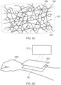
- Figs. 2A to 2D show components of an example apparatus 101 according to examples of the disclosure.
- Fig. 2A shows example sensors 105 that may be used.
- the sensors 105 comprise functionalized particles 203.
- the functionalized particles 203 comprise spherical particles. It is to be appreciated that other shapes of particles could be used in other examples. For instance the particles could comprise fibres, elongated shapes or any suitable shapes.
- the functionalized particles 203 may be fabricated so that the functionalized particles 203 have a selected size and/or shape.
- the size and/or shape of the functionalized particles 203 may be selected so as to facilitate the detection of a specific parameter.
- the size and/or shape of the functionalized particles 203 may be selected so as to improve the efficiency with which the functionalized particles 203 can detect the specific parameter.
- the functionalized particles 203 may be fabricated using any suitable processes such as bottom-up chemical synthesis, homogenization, microfluidics and/or any other suitable process.
- the functionalized particles 203 may be functionalized so as to increase the affinity of the functionalized particles 203 to a particular chemical entity or structure. This may make it easier for the functionalized particles 203 to bind to another chemical entity. In some examples the functionalized particles 203 may be functionalized so that the functionalized particles 203 bind selectively to a particular chemical entity. This ensures that any change in the physical properties of the sensors 105 can be attributed to the presence of the selected chemical entity. As an example, the sensors 105 may be intended to detect glucose levels. In such examples the functionalized particles 203 may be configured to comprise phenylboronic acids derivatives which can be reversibly bound to glucose. In some examples the functionalized particles 203 may be configured to comprise aptamers which can be reversible bound to target nucleic acids, proteins, peptides or any other suitable parameters.
- the functionalized particles 203 could comprise microparticles, nanoparticles or any other suitable sized particles.
- the functionalized particles 203 are configured to increase in size in the presence of a parameter as indicated by the arrow 201. This increase in size acts as an amplifier of the parameter and may enable the presence of the parameter to be quantified.
- the increase in size of the functionalized particles 203 could be caused by the functionalized particles 203 binding to a parameter.
- a chemical entity of the functionalized particles 203 could bind to a parameter comprising a corresponding chemical entity which increases the size of the functionalized particles 203.
- the binding could also change the shape of the functionalized particles 203.
- the parameter could provide an indication of the progress of a wound healing process.
- the parameter could comprise bacteria, temperature, pH level, chemical entity, moisture, oxygenation levels or any other parameter that changes as a wound heals.
- the parameter could be an indication of a subject's general health. For example glucose levels or temperature may provide an indication of a subject's physical condition independently of a wound healing process.
- Fig. 2B shows some example artificial skin 103 before the plurality of sensors 105 are added.
- the artificial skin 103 comprises a matrix 205 of skin tissue that can be used to support the plurality of sensors 105.
- the matrix 205 may be formed from fibrous strands of the material used for the artificial skin 103.
- the artificial skin 103 may be a flexible material that can be configured to conform with a subject's skin.
- the artificial skin 103 could be provided as a gel which can be coated onto a subject's skin.
- the artificial skin 103 could be formed by a process such as three dimensional printing so as to fit into a specific portion of a subject's skin.
- Fig. 2C shows an example apparatus 101 which has been formed from plurality of sensors 105 as shown in Fig. 2A and the artificial skin 103 as shown in Fig. 2B .
- the apparatus 101 may be formed by combining the sensors 105 with the artificial skin 103. Any suitable method may be used to combine the sensors 105 with the artificial skin 103. For instance, where the artificial skin 103 is formed from a gel or liquid the plurality of sensors 105 could be mixed into the artificial skin 103.
- the plurality of sensors 105 may be combined with the artificial skin 103 so that there is a selected density of sensors 105 within the skin 103.
- the density of sensors 105 may be selected so as to enable a parameter to be adequately detected. In some examples the density of sensors 105 may be selected so as to enable a detected parameter to be quantified.
- the plurality of sensors 105 may be homogenously distributed throughout the artificial skin 103.
- the homogenous distribution of the plurality of sensors 105 may enable the detected parameter to be quantified.
- the homogenous distribution of the plurality of sensors 105 may enable more detailed information about the healing of a wound, or other biometric parameters, to be obtained.
- Fig. 2D shows an example apparatus 101 in use.
- the apparatus 101 also comprises a protective surface 207 which is provided overlaying the portion of artificial skin 103.
- the protective surface 207 may provide an outer surface of the apparatus 101.
- the protective surface 207 could comprise a partially permeable membrane which enables some particles to pass through the protective surface 207 but prevents some other particles from passing through.
- the protective surface 207 could enable some gases to pass through but may be configured to prevent moisture loss through the membrane.
- the protective surface 207 provides an interface between the plurality of sensors 105 within the apparatus 101 and an external detector 211.
- the protective surface 207 may be transparent to any light, or other probing means, that is used by the detector 211. In some examples the protective surface 207 may be partially transparent.
- the protective surface 207 may also be configured to provide mechanical support to the artificial skin 103.
- the protective surface 207 may be flexible so as to enable the apparatus 101 which comprises the protective surface to conform to the skin of the subject.
- the protective surface 207 may comprise any suitable material.
- the protective surface 207 may comprise a silicone based film or any other suitable material.
- the apparatus 101 has been applied to the skin on a subject's arm 209.
- Any suitable means may be used to apply the apparatus 101 to the subject's arm 209.
- the artificial skin 103 could be formed as a gel with the sensors 105 suspended within the gel. The gel may then be coated onto a portion of the subject's skin. For example the gel may be coated over a wound or other portion of damaged skin.
- the portion of artificial skin 103 may be sized and shaped so as to fit into a specific portion of skin of the subject. For example, three dimensional printing, or any other suitable method, may be used to form a portion of artificial skin 103 which is sized and shaped so as to fit into a specific wound.
- a detector 211 is used to monitor the physical properties of the plurality of sensors 105.
- the detector 211 comprises a hand-held scanner that can be scanned across the apparatus 101 and/or other parts of the subject's body.
- the detector could be a fixed detector which could be located in an environment such as a hospital or a laboratory. The subject could then be positioned in proximity to the detector 211 to enable the physical properties of the sensors 105 to be monitored.
- the detector 211 could be an optical detector. This may enable optical properties of the sensors 105 to be detected. The detector 211 could detect changes in the way the sensors 105 interact with an input beam of light. In some examples the detector could be an optical coherence tomography detector which is configured to detect the backscattered and/or reflected light. This could be used to detect changes in the size and/or shape of the sensors 105. For example the optical coherence tomography may be configured to detect a change in size of shape of functionalized particles 203 caused by the presence of a parameter.
- the detector 211 comprises an optical detector this enables the physical properties of the sensors 105 to be monitored using a beam of light, or other type of electromagnetic radiation. This may enable the physical properties of the sensor 105 to be monitored without requiring any electrical connections to the sensors 105 or without requiring any electrodes or other coupling devices being added to the subject's skin.
- Figs. 2A and 2D provide an apparatus 101 comprising artificial skin 103 which enables parameters within the subject's skin to be monitored.
- the change of the physical property of the sensors 105 is caused by the sensors 105 binding to a parameter. It is to be appreciated that other processes could cause the change in other examples of the disclosure. For instance, in some examples there could be an oxidation or reduction of chemicals within the functionalized particles 203 which could cause a change in the optical properties, or other physical properties, of the functionalized particles 203.
- the plurality of sensors 105 have a homogenous distribution through the artificial skin 103. In other examples the distribution does not need to be homogenous. For instance, if the apparatus 101 has been formed by a process such as three dimensional printing the process may be controlled so that selected types of sensors in a selected density are provided at different locations within the apparatus 101. This could enable different types of sensors 105 in different densities to be provided within the same apparatus 101.
- Fig. 3 shows a system 301 comprising an example apparatus 101 and a detector 211.
- the example apparatus 101 comprises at least one portion of artificial skin 103, a plurality of sensors 105 dispersed within the artificial skin 103 and a protective layer 207 overlaying the artificial skin 103.
- the detector 211 could be a handheld optical detector or any other suitable type of detector.
- the detector 211 is configured to detect modification of the physical properties of the sensors 105.
- the apparatus 103 is provided covering a wound 305.
- the apparatus 101 is positioned so that it completely covers the wound 305.
- the apparatus 101 is positioned so that the artificial skin 103 of the apparatus 101 is in contact with the undamaged skin 303 which surrounds the wound 305. This may enable cellular integration of the artificial skin 103 with the undamaged skin 303.
- the sensors 105 interact with the parameter so as to cause a change in the optical properties of the sensors 105.
- the change could be the change in the wavelength of light that is absorbed by the sensors. This change in the absorption of the light then produces a change in the relative intensity of the light that is detected by the detector 211.
- Plot 313 shows how the intensity of the light detected by the detector 211 may change as the physical properties of the sensor 105 is modified.
- the wavelengths of light that are detected can be determined using spectral analysis or any other suitable means. The outputs of the detector 211 can therefore give an indication of the presence of the parameter within the wound 305.
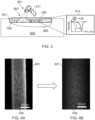
- Figs. 4A and 4B show an example sensor 105 which may be used in some examples of the disclosure.
- Fig. 4A shows the sensor 105 before it has been exposed to a parameter and
- Fig. 4B shows the sensor 105 after it has been exposed to a parameter.
- the sensor 105 is degraded by exposure to the parameter.
- the parameter could be a chemical entity that is present in the subject's skin.
- the parameter could be a chemical entity that is present in a wound.
- Other parameters could be used in other examples of the disclosure.
- the sensor 105 comprises an elongated microparticle 401.
- the elongated microparticle 401 has a diameter of the order of 100 micrometers. In some examples the elongated microparticle 401 could provide a microfibre.
- the elongated microparticle 401 Before the elongated microparticle 401 is exposed to the parameter the elongated microparticle 401 has clearly defined edges. The clearly defined edges are shown in Fig. 4A . After the elongated microparticle 401 has been exposed to the parameter the edges have degraded so that they are no longer clearly defined. This degraded elongated microparticle 401 is shown in Fig. 4B . The degradation of the edges of the elongated microparticle 401 changes the shape of the elongated microparticle 401. This change in shape can be detected by a detector 211 such as an optical coherence tomography detector.
- the degradation of the edges of the elongated microparticle 401 may also cause changes in other physical properties of the sensor 105 such as the refractive index of the wavelengths of light that are absorbed by the elongated microparticle 401. These changes can be detected by an optical detector or by any other suitable means.
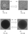
- Figs. 5A and 5B show another example sensor 105 which may be used in some examples of the disclosure.
- Fig. 5A shows the sensor 105 before it has been exposed to a parameter and
- Fig. 5B shows the sensor 105 after it has been exposed to a parameter.
- the sensor 105 is degraded by exposure to the parameter.
- the parameter could be a chemical entity that is present in the subject's skin.
- the parameter could be a chemical entity that is present in a wound.
- Other parameters could be used in other examples of the disclosure.
- the sensor 105 comprises a substantially spherical microparticle 501.
- Figs, 5A and 5B show a cross section of the substantially spherical microparticle 501.
- the substantially spherical microparticle 501 has a diameter of the order of 20 micrometers.
- the substantially spherical microparticle 501 Before the substantially spherical microparticle 501 is exposed to the parameter the substantially spherical microparticle 501 has clearly defined edges. The clearly defined edges are shown in Fig. 5A . After the substantially spherical microparticle 501 has been exposed to the parameter the edges have degraded so that they are no longer clearly defined. This degraded substantially spherical microparticle 501 is shown in Fig. 5B . The degradation of the edges of the substantially spherical microparticle 501 changes the shape of the substantially spherical microparticle 501. This change in shape can be detected by a detector 211 such as an optical coherence tomography detector.
- the degradation of the edges of the substantially spherical microparticle 501 may also cause changes in other physical properties of the sensor 105 such as the refractive index of the wavelengths of light that are absorbed by the substantially spherical microparticle 501. These changes can be detected by an optical detector or by any other suitable means.
- Figs. 6A and 6B show another example sensor 105 which may be used in some examples of the disclosure.
- Fig. 6A shows the sensor 105 before it has been exposed to a parameter and
- Fig. 6B shows the sensor 105 after it has been exposed to a parameter.
- the sensor 105 is modified by exposure to the parameter so that the contrast of the sensor 105 relative to the artificial skin 103 changes.
- the parameter could be a chemical entity that is present in the subject's skin.
- the parameter could be a chemical entity that is present in a wound.
- Other parameters could be used in other examples of the disclosure.
- the sensor 105 comprises a substantially spherical microparticle 601.
- the substantially spherical microparticle 601 could have a diameter of any suitable size.
- the substantially spherical microparticle 601 Before the substantially spherical microparticle 601 is exposed to the parameter the substantially spherical microparticle 601 has clearly defined edges which show a strong contrast with the surrounding material as shown in Fig. 6A . After the substantially spherical microparticle 601 has been exposed to the parameter the edges have been modified so that they are no longer clearly defined and the contrast with the surrounding material is less strong. This degraded substantially spherical microparticle 601 is shown in Fig. 6B .
- the change in the contrast between the substantially spherical microparticle 601 and the surrounding material can be detected by a detector 211 such as an optical coherence tomography detector or by ant other suitable means.
- Examples of the disclosure provide an apparatus 101 comprising artificial skin 103 which enables internal monitoring of the user's skin.
- the sensors 105 for monitoring the biometric markers or other parameter are dispersed within the artificial skin 103 this enables the parameters to be directly monitored without having to disturb the artificial skin 103. This allows for non-invasive monitoring of the wound. For example there is no need to remove the artificial skin 103 in order to monitor a wound underneath apparatus 101.
- the apparatus 101 could be used to monitor other biometric markers of a subject that are not related to wound healing.
- the apparatus 101 could be used to monitor glucose levels or any other suitable parameter. This could allow for long term monitoring of the physical condition of a subject.
- the long term monitoring aspect could be configured to cover a time period of weeks or months or even longer.
- the sensors 105 are distributed within the artificial skin 103 this provides for a lightweight and compact method of monitoring the parameters of the user.
- the example apparatus 101 do not require any additional connectors or electrodes to be coupled to a user in order to enable the parameter to be monitored.
- 'comprise' is used in this document with an inclusive not an exclusive meaning. That is any reference to X comprising Y indicates that X may comprise only one Y or may comprise more than one Y. If it is intended to use 'comprise' with an exclusive meaning then it will be made clear in the context by referring to 'comprising only one...' or by using 'consisting'.
- a property of the instance can be a property of only that instance or a property of the class or a property of a sub-class of the class that includes some but not all of the instances in the class. It is therefore implicitly disclosed that a feature described with reference to one example but not with reference to another example, can where possible be used in that other example as part of a working combination but does not necessarily have to be used in that other example.
- 'a' or 'the' is used in this document with an inclusive not an exclusive meaning. That is any reference to X comprising a/the Y indicates that X may comprise only one Y or may comprise more than one Y unless the context clearly indicates the contrary. If it is intended to use 'a' or ⁇ the' with an exclusive meaning then it will be made clear in the context. In some circumstances the use of 'at least one' or 'one or more' may be used to emphasis an inclusive meaning but the absence of these terms should not be taken to infer and exclusive meaning.
- the presence of a feature (or combination of features) in a claim is a reference to that feature) or combination of features) itself and also to features that achieve substantially the same technical effect (equivalent features).
- the equivalent features include, for example, features that are variants and achieve substantially the same result in substantially the same way.
- the equivalent features include, for example, features that perform substantially the same function, in substantially the same way to achieve substantially the same result.
- 'example' or 'for example' or 'can' or 'may' in the text denotes, whether explicitly stated or not, that such features or functions are present in at least the described example, whether described as an example or not, and that they can be, but are not necessarily, present in some of or all other examples.
- 'example', 'for example', 'can' or 'may' refers to a particular instance in a class of examples.
- a property of the instance can be a property of only that instance or a property of the class or a property of a sub-class of the class that includes some but not all of the instances in the class. It is therefore implicitly disclosed that a feature described with reference to one example but not with reference to another example, can where possible be used in that other example as part of a working combination but does not necessarily have to be used in that other example
Landscapes
- Health & Medical Sciences (AREA)
- Life Sciences & Earth Sciences (AREA)
- Physics & Mathematics (AREA)
- Veterinary Medicine (AREA)
- Public Health (AREA)
- Engineering & Computer Science (AREA)
- Biomedical Technology (AREA)
- Heart & Thoracic Surgery (AREA)
- General Health & Medical Sciences (AREA)
- Animal Behavior & Ethology (AREA)
- Surgery (AREA)
- Molecular Biology (AREA)
- Medical Informatics (AREA)
- Biophysics (AREA)
- Pathology (AREA)
- Transplantation (AREA)
- Optics & Photonics (AREA)
- Vascular Medicine (AREA)
- Oral & Maxillofacial Surgery (AREA)
- Dermatology (AREA)
- Cardiology (AREA)
- Radiology & Medical Imaging (AREA)
- Nuclear Medicine, Radiotherapy & Molecular Imaging (AREA)
- Emergency Medicine (AREA)
- Immunology (AREA)
- Investigating Or Analysing Materials By Optical Means (AREA)
- Measurement Of The Respiration, Hearing Ability, Form, And Blood Characteristics Of Living Organisms (AREA)
- Materials For Medical Uses (AREA)
- Prostheses (AREA)
Claims (15)
- Vorrichtung (101), umfassend:mindestens einen Abschnitt künstlicher Haut (103);eine Vielzahl von Sensoren (105), die innerhalb des mindestens einen Abschnitts künstlicher Haut verteilt sind;wobei die Vielzahl von Sensoren mindestens eine physikalische Eigenschaft aufweisen, die dazu ausgestaltet ist, verändert zu werden, wenn die Vielzahl von Sensoren einem Parameter ausgesetzt sind, derart dass die Veränderung der physikalischen Eigenschaft durch einen externen Detektor (211) detektiert werden kann, und dadurch gekennzeichnet, dass die Vielzahl von Sensoren funktionalisierte Partikel (203) umfassen.
- Vorrichtung nach Anspruch 1, die eine Schutzoberfläche (207) umfasst, die den mindestens einen Abschnitt künstlicher Haut überlagernd bereitgestellt ist.
- Vorrichtung nach Anspruch 2, wobei die Schutzoberfläche eine Grenzfläche zwischen der Vielzahl von Sensoren und dem externen Detektor bereitstellt.
- Vorrichtung nach einem der vorhergehenden Ansprüche, wobei der mindestens eine Abschnitt künstlicher Haut dazu ausgestaltet ist, sich mit der Haut (303) einer Person zu integrieren.
- Vorrichtung nach einem der vorhergehenden Ansprüche, wobei der mindestens eine Abschnitt künstlicher Haut dazu ausgestaltet ist, eine Wunde (305) einer Person zu bedecken.
- Vorrichtung nach einem der vorhergehenden Ansprüche, wobei der mindestens eine Abschnitt künstlicher Haut dazu ausgestaltet ist, sich an die Form einer beschädigten Haut einer Person anzupassen.
- Vorrichtung nach einem der vorhergehenden Ansprüche, wobei der mindestens eine Abschnitt künstlicher Haut eine Matrix (205) von Hautgewebe umfasst, die dazu ausgestaltet ist, die Vielzahl von Sensoren zu unterstützen.
- Vorrichtung nach einem der vorhergehenden Ansprüche, wobei mindestens einer der funktionalisierten Partikel dazu ausgestaltet ist, sich an eine chemische Substanz zu binden, derart dass die Bindung eine physikalische Eigenschaft des funktionalisierten Partikels verändert.
- Vorrichtung nach einem der vorhergehenden Ansprüche, wobei die funktionalisierten Partikel einen Durchmesser aufweisen, der kleiner als 100 Mikrometer ist.
- Vorrichtung nach einem der vorhergehenden Ansprüche, wobei die Vorrichtung eine Vielzahl von unterschiedlichen Typen von Sensoren umfasst, wobei die unterschiedlichen Typen von Sensoren dazu ausgestaltet sind, unterschiedliche Parameter zu detektieren und/oder die unterschiedlichen Typen von Sensoren unterschiedliche Formen aufweisen.
- Vorrichtung nach einem der vorhergehenden Ansprüche, wobei der Parameter, der von der Vielzahl von Sensoren detektiert wird, mindestens eines von Glucosespiegeln, Bakterien, Temperatur, pH-Wert, chemische Substanz, Feuchtigkeit, Sauerstoffgehalten umfasst.
- Vorrichtung nach einem der vorhergehenden Ansprüche, wobei die physikalische Eigenschaft der Vielzahl von Sensoren, die verändert wird, mindestens eines von einer optischen Eigenschaft, einer Größe des Sensors umfasst.
- Vorrichtung nach einem der vorhergehenden Ansprüche, wobei der externe Detektor einen optischen Kohärenztomografiedetektor umfasst.
- Detektionssystem (301), das eine Vorrichtung nach einem der vorhergehenden Ansprüche und einen Detektor umfasst, der dazu ausgestaltet ist, Veränderung der physikalischen Eigenschaften der Sensoren zu detektieren.
- Detektionssystem nach Anspruch 14, wobei der Detektor von der Vorrichtung entfernt ist.
Priority Applications (4)
| Application Number | Priority Date | Filing Date | Title |
|---|---|---|---|
| EP18183393.0A EP3593708B1 (de) | 2018-07-13 | 2018-07-13 | Künstliche haut |
| US17/252,554 US12178698B2 (en) | 2018-07-13 | 2019-07-05 | Artificial skin |
| PCT/FI2019/050526 WO2020012064A1 (en) | 2018-07-13 | 2019-07-05 | Artificial skin |
| JP2021500303A JP7035268B2 (ja) | 2018-07-13 | 2019-07-05 | 人工皮膚 |
Applications Claiming Priority (1)
| Application Number | Priority Date | Filing Date | Title |
|---|---|---|---|
| EP18183393.0A EP3593708B1 (de) | 2018-07-13 | 2018-07-13 | Künstliche haut |
Publications (2)
| Publication Number | Publication Date |
|---|---|
| EP3593708A1 EP3593708A1 (de) | 2020-01-15 |
| EP3593708B1 true EP3593708B1 (de) | 2024-08-28 |
Family
ID=63079728
Family Applications (1)
| Application Number | Title | Priority Date | Filing Date |
|---|---|---|---|
| EP18183393.0A Active EP3593708B1 (de) | 2018-07-13 | 2018-07-13 | Künstliche haut |
Country Status (4)
| Country | Link |
|---|---|
| US (1) | US12178698B2 (de) |
| EP (1) | EP3593708B1 (de) |
| JP (1) | JP7035268B2 (de) |
| WO (1) | WO2020012064A1 (de) |
Families Citing this family (2)
| Publication number | Priority date | Publication date | Assignee | Title |
|---|---|---|---|---|
| EP4086688A1 (de) | 2021-05-06 | 2022-11-09 | Nokia Technologies Oy | Vorrichtung zur positionierung von komponenten in optischen systemen |
| US12014651B2 (en) | 2021-06-16 | 2024-06-18 | Nokia Technologies Oy | Perfusive tissue phantom |
Family Cites Families (36)
| Publication number | Priority date | Publication date | Assignee | Title |
|---|---|---|---|---|
| US4401122A (en) * | 1979-08-02 | 1983-08-30 | Children's Hospital Medical Center | Cutaneous methods of measuring body substances |
| US5195145A (en) * | 1989-11-13 | 1993-03-16 | Identity Technologies Incorporated | Apparatus to record epidermal topography |
| US5665391A (en) * | 1995-10-12 | 1997-09-09 | Spectral Diagnostics Inc. | Cultured, full-thickness integument substitutes based on three-dimensional matrix membranes |
| US6014246A (en) | 1996-11-06 | 2000-01-11 | University Of Pittsburgh Of The Commonwealth System Of Higher Education | Thermally switchable optical devices |
| AU2001233200A1 (en) | 2000-01-31 | 2001-08-07 | Board Of Regents, The University Of Texas System | Portable sensor array system |
| AU7014001A (en) | 2000-06-23 | 2002-01-08 | Minerva Biotechnologies Corp | Interaction of colloid-immobilized species with species on non-colloidal structures |
| WO2004042403A2 (en) | 2002-11-04 | 2004-05-21 | Ludwig-Maximilian-Uni Versität München | Methods, device and instrument for detection of analytes |
| US20040116866A1 (en) * | 2002-12-17 | 2004-06-17 | William Gorman | Skin attachment apparatus and method for patient infusion device |
| US7830507B2 (en) | 2006-02-13 | 2010-11-09 | Optopo Inc. | Spatially patterned substrates for chemical and biological sensing |
| CA2583034C (en) | 2006-03-03 | 2016-01-05 | James W. Haslett | Bandage with sensors |
| WO2008018933A2 (en) | 2006-05-03 | 2008-02-14 | The Regents Of The University Of California | Detection of protease and protease activity using a single nanocrescent sers probe |
| US8175671B2 (en) * | 2006-09-22 | 2012-05-08 | Nellcor Puritan Bennett Llc | Medical sensor for reducing signal artifacts and technique for using the same |
| US7687678B2 (en) * | 2007-05-10 | 2010-03-30 | Cisco Technology, Inc. | Electronic bandage with flexible electronic controller |
| JP5317031B2 (ja) | 2008-05-07 | 2013-10-16 | 公立大学法人大阪府立大学 | ヘッド−テイル型共重合体の中空ナノ微粒子 |
| ES2715633T3 (es) | 2008-05-20 | 2019-06-05 | Univ Health Network | Dispositivo y método para formación de imágenes y supervisión por fluorescencia |
| EP2549925B1 (de) | 2010-03-24 | 2015-10-21 | Northeastern University | Multimodale Diagnosetechnologie für Krebsläsionen im Frühstadium |
| JP2014503252A (ja) | 2010-11-30 | 2014-02-13 | エーブリー デニソン コーポレイション | 感知パッチ用途 |
| EP2500314A1 (de) | 2011-03-14 | 2012-09-19 | Nederlandse Organisatie voor toegepast -natuurwetenschappelijk onderzoek TNO | Photonischer Kristallsensor |
| US8784895B2 (en) | 2011-03-15 | 2014-07-22 | Northwestern University | Multifunctional metal nanoparticles having a polydopamine-based surface and methods of making and using the same |
| CN103718372B (zh) * | 2011-07-18 | 2016-12-14 | 株式会社Lg化学 | 非水性电解质及其锂二次电池 |
| US9841331B2 (en) * | 2011-09-24 | 2017-12-12 | President And Fellows Of Harvard College | Artificial skin and elastic strain sensor |
| US10265219B2 (en) * | 2012-04-12 | 2019-04-23 | Elwha Llc | Wound dressing monitoring systems including appurtenances for wound dressings |
| US20160135946A1 (en) * | 2013-06-28 | 2016-05-19 | Saga University | Patch-type artificial skin preparation |
| US9784737B2 (en) | 2013-10-15 | 2017-10-10 | Board Of Trustees Of The University Of Arkansas | Nanocomposites, methods of making same, and applications of same for multicolor surface enhanced Raman spectroscopy (SERS) detections |
| EP3233904A4 (de) | 2014-12-15 | 2018-07-25 | Northeastern University | Kollagengewebereparaturvorrichtungen |
| KR101596195B1 (ko) | 2015-02-05 | 2016-02-29 | 경희대학교 산학협력단 | 인공피부센서 및 인공피부센서 기반의 생체 정보 진단 장치 |
| EP3283029A1 (de) * | 2015-04-15 | 2018-02-21 | King Abdullah University Of Science And Technology | Wundverband mit wiederverwendbarer elektronik zur drahtlosen überwachung |
| WO2017049284A1 (en) | 2015-09-17 | 2017-03-23 | Hollister Incorporated | Scaffold-based wound care delivery system and method |
| US10845213B2 (en) * | 2016-01-14 | 2020-11-24 | King Abdullah University Of Science And Technology | Paper based electronics platform |
| WO2017143229A1 (en) * | 2016-02-19 | 2017-08-24 | Kci Licensing, Inc. | Transfected epidermal grafts and methods of making the same |
| US10488677B2 (en) * | 2016-03-03 | 2019-11-26 | Verily Life Sciences Llc | Electronics embedded in rigid gas permeable contact lenses |
| US11717447B2 (en) | 2016-05-13 | 2023-08-08 | Smith & Nephew Plc | Sensor enabled wound monitoring and therapy apparatus |
| CN106344212A (zh) * | 2016-08-23 | 2017-01-25 | 清华大学 | 一种基于液态金属传感的人造皮肤 |
| CN107412872B (zh) | 2017-07-28 | 2020-09-29 | 浙江理工大学 | 一种多层复合人工皮肤传感器的制备方法 |
| US20190060126A1 (en) | 2017-08-30 | 2019-02-28 | Hill-Rom Services, Inc. | Systems for monitoring wounds and wound dressing status and systems for protecting wounds |
| EP3460472B1 (de) | 2017-09-22 | 2024-09-18 | Nokia Technologies Oy | Funktionalisierte partikel |
-
2018
- 2018-07-13 EP EP18183393.0A patent/EP3593708B1/de active Active
-
2019
- 2019-07-05 WO PCT/FI2019/050526 patent/WO2020012064A1/en not_active Ceased
- 2019-07-05 US US17/252,554 patent/US12178698B2/en active Active
- 2019-07-05 JP JP2021500303A patent/JP7035268B2/ja active Active
Also Published As
| Publication number | Publication date |
|---|---|
| JP2021524338A (ja) | 2021-09-13 |
| WO2020012064A1 (en) | 2020-01-16 |
| US12178698B2 (en) | 2024-12-31 |
| EP3593708A1 (de) | 2020-01-15 |
| US20210267749A1 (en) | 2021-09-02 |
| JP7035268B2 (ja) | 2022-03-14 |
Similar Documents
| Publication | Publication Date | Title |
|---|---|---|
| Tang et al. | Wearable sensors and systems for wound healing-related pH and temperature detection | |
| Wang et al. | Wound management materials and technologies from bench to bedside and beyond | |
| Hussain et al. | Sweat-based noninvasive skin-patchable urea biosensors with photonic interpenetrating polymer network films integrated into PDMS chips | |
| Cheng et al. | Recent progress in intelligent wearable sensors for health monitoring and wound healing based on biofluids | |
| Mao et al. | Passive and active microrheology for biomedical systems | |
| Charkhabi et al. | Monitoring wound health through bandages with passive LC resonant sensors | |
| Piro et al. | Recent advances in skin chemical sensors | |
| Prathap et al. | Quantifying efficacy of the fiber bragg grating sensors in medical applications: a survey | |
| EP3593708B1 (de) | Künstliche haut | |
| Tsegay et al. | Smart 3D printed auxetic hydrogel skin wound dressings | |
| ITUD20120114A1 (it) | Dispositivo transdermico per la rilevazione fluorimetrica di un analita in un fluido biologico e apparecchiatura di analisi associata a detto dispositivo transdermico | |
| Tran et al. | Emerging strategies based on sensors for chronic wound monitoring and management | |
| Omidian et al. | Hydrogels in biosensing and medical diagnostics | |
| Jacquet et al. | Ultra‐light extensometer for the assessment of the mechanical properties of the human skin in vivo | |
| Silver et al. | The “Virtual Biopsy” of Cancerous Lesions in 3D: Non-Invasive Differentiation between Melanoma and Other Lesions Using Vibrational Optical Coherence Tomography | |
| Silver et al. | Characterization of the biomechanical properties of skin using vibrational optical coherence tomography: Do changes in the biomechanical properties of skin stroma reflect structural changes in the extracellular matrix of cancerous lesions? | |
| Bontozoglou et al. | Applications of capacitive imaging in human skin texture and hair analysis | |
| Hu et al. | Flexible Eyelid Pressure and Motion Dual-Mode Sensor Using Electric Breakdown-Induced Piezoresistivity and Electrical Potential Sensing | |
| EP3036338A1 (de) | Systeme, verfahren und vorrichtung zur beurteilung der mikrobiata von haut | |
| Spillman Jr | Fiber optic biosensors | |
| Schmidt et al. | Biochemical piezoresistive sensors based on pH-and glucose-sensitive hydrogels for medical applications | |
| JP7208226B2 (ja) | 機能粒子 | |
| Atwa et al. | Integrating nanosensors into stem cells technologies and regenerative medicine | |
| Mitsubayashi | Wearable Biosensing in Medicine and Healthcare | |
| Owda | Passive millimeter-wave imaging for burns diagnostics under dressing materials |
Legal Events
| Date | Code | Title | Description |
|---|---|---|---|
| PUAI | Public reference made under article 153(3) epc to a published international application that has entered the european phase |
Free format text: ORIGINAL CODE: 0009012 |
|
| STAA | Information on the status of an ep patent application or granted ep patent |
Free format text: STATUS: THE APPLICATION HAS BEEN PUBLISHED |
|
| AK | Designated contracting states |
Kind code of ref document: A1 Designated state(s): AL AT BE BG CH CY CZ DE DK EE ES FI FR GB GR HR HU IE IS IT LI LT LU LV MC MK MT NL NO PL PT RO RS SE SI SK SM TR |
|
| AX | Request for extension of the european patent |
Extension state: BA ME |
|
| STAA | Information on the status of an ep patent application or granted ep patent |
Free format text: STATUS: REQUEST FOR EXAMINATION WAS MADE |
|
| 17P | Request for examination filed |
Effective date: 20200714 |
|
| RBV | Designated contracting states (corrected) |
Designated state(s): AL AT BE BG CH CY CZ DE DK EE ES FI FR GB GR HR HU IE IS IT LI LT LU LV MC MK MT NL NO PL PT RO RS SE SI SK SM TR |
|
| GRAP | Despatch of communication of intention to grant a patent |
Free format text: ORIGINAL CODE: EPIDOSNIGR1 |
|
| STAA | Information on the status of an ep patent application or granted ep patent |
Free format text: STATUS: GRANT OF PATENT IS INTENDED |
|
| RIC1 | Information provided on ipc code assigned before grant |
Ipc: A61F 2/10 20060101ALI20240305BHEP Ipc: A61L 27/60 20060101ALI20240305BHEP Ipc: A61B 5/00 20060101AFI20240305BHEP |
|
| INTG | Intention to grant announced |
Effective date: 20240326 |
|
| RIN1 | Information on inventor provided before grant (corrected) |
Inventor name: ZHENG, MINGDE Inventor name: SHAH, SHREYAS |
|
| GRAS | Grant fee paid |
Free format text: ORIGINAL CODE: EPIDOSNIGR3 |
|
| GRAA | (expected) grant |
Free format text: ORIGINAL CODE: 0009210 |
|
| STAA | Information on the status of an ep patent application or granted ep patent |
Free format text: STATUS: THE PATENT HAS BEEN GRANTED |
|
| AK | Designated contracting states |
Kind code of ref document: B1 Designated state(s): AL AT BE BG CH CY CZ DE DK EE ES FI FR GB GR HR HU IE IS IT LI LT LU LV MC MK MT NL NO PL PT RO RS SE SI SK SM TR |
|
| REG | Reference to a national code |
Ref country code: GB Ref legal event code: FG4D |
|
| REG | Reference to a national code |
Ref country code: CH Ref legal event code: EP |
|
| REG | Reference to a national code |
Ref country code: DE Ref legal event code: R096 Ref document number: 602018073560 Country of ref document: DE |
|
| REG | Reference to a national code |
Ref country code: IE Ref legal event code: FG4D |
|
| REG | Reference to a national code |
Ref country code: LT Ref legal event code: MG9D |
|
| PG25 | Lapsed in a contracting state [announced via postgrant information from national office to epo] |
Ref country code: NO Free format text: LAPSE BECAUSE OF FAILURE TO SUBMIT A TRANSLATION OF THE DESCRIPTION OR TO PAY THE FEE WITHIN THE PRESCRIBED TIME-LIMIT Effective date: 20241128 |
|
| REG | Reference to a national code |
Ref country code: AT Ref legal event code: MK05 Ref document number: 1717042 Country of ref document: AT Kind code of ref document: T Effective date: 20240828 |
|
| PG25 | Lapsed in a contracting state [announced via postgrant information from national office to epo] |
Ref country code: NL Free format text: LAPSE BECAUSE OF FAILURE TO SUBMIT A TRANSLATION OF THE DESCRIPTION OR TO PAY THE FEE WITHIN THE PRESCRIBED TIME-LIMIT Effective date: 20240828 Ref country code: PL Free format text: LAPSE BECAUSE OF FAILURE TO SUBMIT A TRANSLATION OF THE DESCRIPTION OR TO PAY THE FEE WITHIN THE PRESCRIBED TIME-LIMIT Effective date: 20240828 Ref country code: GR Free format text: LAPSE BECAUSE OF FAILURE TO SUBMIT A TRANSLATION OF THE DESCRIPTION OR TO PAY THE FEE WITHIN THE PRESCRIBED TIME-LIMIT Effective date: 20241129 Ref country code: FI Free format text: LAPSE BECAUSE OF FAILURE TO SUBMIT A TRANSLATION OF THE DESCRIPTION OR TO PAY THE FEE WITHIN THE PRESCRIBED TIME-LIMIT Effective date: 20240828 Ref country code: PT Free format text: LAPSE BECAUSE OF FAILURE TO SUBMIT A TRANSLATION OF THE DESCRIPTION OR TO PAY THE FEE WITHIN THE PRESCRIBED TIME-LIMIT Effective date: 20241230 |
|
| PG25 | Lapsed in a contracting state [announced via postgrant information from national office to epo] |
Ref country code: BG Free format text: LAPSE BECAUSE OF FAILURE TO SUBMIT A TRANSLATION OF THE DESCRIPTION OR TO PAY THE FEE WITHIN THE PRESCRIBED TIME-LIMIT Effective date: 20240828 |
|
| PG25 | Lapsed in a contracting state [announced via postgrant information from national office to epo] |
Ref country code: LV Free format text: LAPSE BECAUSE OF FAILURE TO SUBMIT A TRANSLATION OF THE DESCRIPTION OR TO PAY THE FEE WITHIN THE PRESCRIBED TIME-LIMIT Effective date: 20240828 |
|
| REG | Reference to a national code |
Ref country code: NL Ref legal event code: MP Effective date: 20240828 |
|
| PG25 | Lapsed in a contracting state [announced via postgrant information from national office to epo] |
Ref country code: AT Free format text: LAPSE BECAUSE OF FAILURE TO SUBMIT A TRANSLATION OF THE DESCRIPTION OR TO PAY THE FEE WITHIN THE PRESCRIBED TIME-LIMIT Effective date: 20240828 Ref country code: IS Free format text: LAPSE BECAUSE OF FAILURE TO SUBMIT A TRANSLATION OF THE DESCRIPTION OR TO PAY THE FEE WITHIN THE PRESCRIBED TIME-LIMIT Effective date: 20241228 |
|
| PG25 | Lapsed in a contracting state [announced via postgrant information from national office to epo] |
Ref country code: HR Free format text: LAPSE BECAUSE OF FAILURE TO SUBMIT A TRANSLATION OF THE DESCRIPTION OR TO PAY THE FEE WITHIN THE PRESCRIBED TIME-LIMIT Effective date: 20240828 |
|
| PG25 | Lapsed in a contracting state [announced via postgrant information from national office to epo] |
Ref country code: ES Free format text: LAPSE BECAUSE OF FAILURE TO SUBMIT A TRANSLATION OF THE DESCRIPTION OR TO PAY THE FEE WITHIN THE PRESCRIBED TIME-LIMIT Effective date: 20240828 Ref country code: RS Free format text: LAPSE BECAUSE OF FAILURE TO SUBMIT A TRANSLATION OF THE DESCRIPTION OR TO PAY THE FEE WITHIN THE PRESCRIBED TIME-LIMIT Effective date: 20241128 |
|
| PG25 | Lapsed in a contracting state [announced via postgrant information from national office to epo] |
Ref country code: RS Free format text: LAPSE BECAUSE OF FAILURE TO SUBMIT A TRANSLATION OF THE DESCRIPTION OR TO PAY THE FEE WITHIN THE PRESCRIBED TIME-LIMIT Effective date: 20241128 Ref country code: PT Free format text: LAPSE BECAUSE OF FAILURE TO SUBMIT A TRANSLATION OF THE DESCRIPTION OR TO PAY THE FEE WITHIN THE PRESCRIBED TIME-LIMIT Effective date: 20241230 Ref country code: PL Free format text: LAPSE BECAUSE OF FAILURE TO SUBMIT A TRANSLATION OF THE DESCRIPTION OR TO PAY THE FEE WITHIN THE PRESCRIBED TIME-LIMIT Effective date: 20240828 Ref country code: NO Free format text: LAPSE BECAUSE OF FAILURE TO SUBMIT A TRANSLATION OF THE DESCRIPTION OR TO PAY THE FEE WITHIN THE PRESCRIBED TIME-LIMIT Effective date: 20241128 Ref country code: NL Free format text: LAPSE BECAUSE OF FAILURE TO SUBMIT A TRANSLATION OF THE DESCRIPTION OR TO PAY THE FEE WITHIN THE PRESCRIBED TIME-LIMIT Effective date: 20240828 Ref country code: LV Free format text: LAPSE BECAUSE OF FAILURE TO SUBMIT A TRANSLATION OF THE DESCRIPTION OR TO PAY THE FEE WITHIN THE PRESCRIBED TIME-LIMIT Effective date: 20240828 Ref country code: IS Free format text: LAPSE BECAUSE OF FAILURE TO SUBMIT A TRANSLATION OF THE DESCRIPTION OR TO PAY THE FEE WITHIN THE PRESCRIBED TIME-LIMIT Effective date: 20241228 Ref country code: HR Free format text: LAPSE BECAUSE OF FAILURE TO SUBMIT A TRANSLATION OF THE DESCRIPTION OR TO PAY THE FEE WITHIN THE PRESCRIBED TIME-LIMIT Effective date: 20240828 Ref country code: GR Free format text: LAPSE BECAUSE OF FAILURE TO SUBMIT A TRANSLATION OF THE DESCRIPTION OR TO PAY THE FEE WITHIN THE PRESCRIBED TIME-LIMIT Effective date: 20241129 Ref country code: FI Free format text: LAPSE BECAUSE OF FAILURE TO SUBMIT A TRANSLATION OF THE DESCRIPTION OR TO PAY THE FEE WITHIN THE PRESCRIBED TIME-LIMIT Effective date: 20240828 Ref country code: ES Free format text: LAPSE BECAUSE OF FAILURE TO SUBMIT A TRANSLATION OF THE DESCRIPTION OR TO PAY THE FEE WITHIN THE PRESCRIBED TIME-LIMIT Effective date: 20240828 Ref country code: BG Free format text: LAPSE BECAUSE OF FAILURE TO SUBMIT A TRANSLATION OF THE DESCRIPTION OR TO PAY THE FEE WITHIN THE PRESCRIBED TIME-LIMIT Effective date: 20240828 Ref country code: AT Free format text: LAPSE BECAUSE OF FAILURE TO SUBMIT A TRANSLATION OF THE DESCRIPTION OR TO PAY THE FEE WITHIN THE PRESCRIBED TIME-LIMIT Effective date: 20240828 |
|
| PG25 | Lapsed in a contracting state [announced via postgrant information from national office to epo] |
Ref country code: SM Free format text: LAPSE BECAUSE OF FAILURE TO SUBMIT A TRANSLATION OF THE DESCRIPTION OR TO PAY THE FEE WITHIN THE PRESCRIBED TIME-LIMIT Effective date: 20240828 Ref country code: DK Free format text: LAPSE BECAUSE OF FAILURE TO SUBMIT A TRANSLATION OF THE DESCRIPTION OR TO PAY THE FEE WITHIN THE PRESCRIBED TIME-LIMIT Effective date: 20240828 Ref country code: RO Free format text: LAPSE BECAUSE OF FAILURE TO SUBMIT A TRANSLATION OF THE DESCRIPTION OR TO PAY THE FEE WITHIN THE PRESCRIBED TIME-LIMIT Effective date: 20240828 |
|
| PG25 | Lapsed in a contracting state [announced via postgrant information from national office to epo] |
Ref country code: EE Free format text: LAPSE BECAUSE OF FAILURE TO SUBMIT A TRANSLATION OF THE DESCRIPTION OR TO PAY THE FEE WITHIN THE PRESCRIBED TIME-LIMIT Effective date: 20240828 |
|
| PG25 | Lapsed in a contracting state [announced via postgrant information from national office to epo] |
Ref country code: CZ Free format text: LAPSE BECAUSE OF FAILURE TO SUBMIT A TRANSLATION OF THE DESCRIPTION OR TO PAY THE FEE WITHIN THE PRESCRIBED TIME-LIMIT Effective date: 20240828 |
|
| PG25 | Lapsed in a contracting state [announced via postgrant information from national office to epo] |
Ref country code: SK Free format text: LAPSE BECAUSE OF FAILURE TO SUBMIT A TRANSLATION OF THE DESCRIPTION OR TO PAY THE FEE WITHIN THE PRESCRIBED TIME-LIMIT Effective date: 20240828 Ref country code: IT Free format text: LAPSE BECAUSE OF FAILURE TO SUBMIT A TRANSLATION OF THE DESCRIPTION OR TO PAY THE FEE WITHIN THE PRESCRIBED TIME-LIMIT Effective date: 20240828 |
|
| REG | Reference to a national code |
Ref country code: DE Ref legal event code: R097 Ref document number: 602018073560 Country of ref document: DE |
|
| PLBE | No opposition filed within time limit |
Free format text: ORIGINAL CODE: 0009261 |
|
| STAA | Information on the status of an ep patent application or granted ep patent |
Free format text: STATUS: NO OPPOSITION FILED WITHIN TIME LIMIT |
|
| PGFP | Annual fee paid to national office [announced via postgrant information from national office to epo] |
Ref country code: GB Payment date: 20250529 Year of fee payment: 8 |
|
| 26N | No opposition filed |
Effective date: 20250530 |
|
| PG25 | Lapsed in a contracting state [announced via postgrant information from national office to epo] |
Ref country code: SE Free format text: LAPSE BECAUSE OF FAILURE TO SUBMIT A TRANSLATION OF THE DESCRIPTION OR TO PAY THE FEE WITHIN THE PRESCRIBED TIME-LIMIT Effective date: 20240828 |