EP3593359B1 - Digital systems and methods for high precision control in nuclear reactors - Google Patents
Digital systems and methods for high precision control in nuclear reactors Download PDFInfo
- Publication number
- EP3593359B1 EP3593359B1 EP18763447.2A EP18763447A EP3593359B1 EP 3593359 B1 EP3593359 B1 EP 3593359B1 EP 18763447 A EP18763447 A EP 18763447A EP 3593359 B1 EP3593359 B1 EP 3593359B1
- Authority
- EP
- European Patent Office
- Prior art keywords
- channel
- control rod
- rod drive
- digital
- control
- Prior art date
- Legal status (The legal status is an assumption and is not a legal conclusion. Google has not performed a legal analysis and makes no representation as to the accuracy of the status listed.)
- Active
Links
Images

Classifications
-
- G—PHYSICS
- G21—NUCLEAR PHYSICS; NUCLEAR ENGINEERING
- G21C—NUCLEAR REACTORS
- G21C7/00—Control of nuclear reaction
- G21C7/36—Control circuits
-
- G—PHYSICS
- G21—NUCLEAR PHYSICS; NUCLEAR ENGINEERING
- G21C—NUCLEAR REACTORS
- G21C17/00—Monitoring; Testing ; Maintaining
- G21C17/10—Structural combination of fuel element, control rod, reactor core, or moderator structure with sensitive instruments, e.g. for measuring radioactivity, strain
- G21C17/12—Sensitive element forming part of control element
-
- G—PHYSICS
- G21—NUCLEAR PHYSICS; NUCLEAR ENGINEERING
- G21D—NUCLEAR POWER PLANT
- G21D3/00—Control of nuclear power plant
- G21D3/001—Computer implemented control
-
- G—PHYSICS
- G21—NUCLEAR PHYSICS; NUCLEAR ENGINEERING
- G21C—NUCLEAR REACTORS
- G21C7/00—Control of nuclear reaction
- G21C7/06—Control of nuclear reaction by application of neutron-absorbing material, i.e. material with absorption cross-section very much in excess of reflection cross-section
- G21C7/08—Control of nuclear reaction by application of neutron-absorbing material, i.e. material with absorption cross-section very much in excess of reflection cross-section by displacement of solid control elements, e.g. control rods
- G21C7/12—Means for moving control elements to desired position
- G21C7/14—Mechanical drive arrangements
-
- H—ELECTRICITY
- H03—ELECTRONIC CIRCUITRY
- H03M—CODING; DECODING; CODE CONVERSION IN GENERAL
- H03M1/00—Analogue/digital conversion; Digital/analogue conversion
-
- H—ELECTRICITY
- H03—ELECTRONIC CIRCUITRY
- H03M—CODING; DECODING; CODE CONVERSION IN GENERAL
- H03M1/00—Analogue/digital conversion; Digital/analogue conversion
- H03M1/001—Analogue/digital/analogue conversion
-
- Y—GENERAL TAGGING OF NEW TECHNOLOGICAL DEVELOPMENTS; GENERAL TAGGING OF CROSS-SECTIONAL TECHNOLOGIES SPANNING OVER SEVERAL SECTIONS OF THE IPC; TECHNICAL SUBJECTS COVERED BY FORMER USPC CROSS-REFERENCE ART COLLECTIONS [XRACs] AND DIGESTS
- Y02—TECHNOLOGIES OR APPLICATIONS FOR MITIGATION OR ADAPTATION AGAINST CLIMATE CHANGE
- Y02E—REDUCTION OF GREENHOUSE GAS [GHG] EMISSIONS, RELATED TO ENERGY GENERATION, TRANSMISSION OR DISTRIBUTION
- Y02E30/00—Energy generation of nuclear origin
- Y02E30/30—Nuclear fission reactors
Definitions
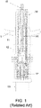
- FIG. 1 is a cross-sectional illustration of a related art control rod drive 10 useable in a nuclear reactor.
- related art control rod drive 10 may be a Fine Motion Control Rod Drive (FMCRD) as used in next generation BWRs like ESBWRs
- FMCRD Fine Motion Control Rod Drive
- control rod drive is housed outside, such as below, reactor pressure vessel 1, where drive 10 inserts or withdraws a control element, such as a control blade (not shown), attached thereto via bayonet coupling 15.
- Hollow piston 16 connects to bayonet coupling 15 and is vertically moveable inside of an outer tube in drive 10.
- Drive 10 includes ball screw 11 coupled with ball nut 12 that drives screw 11 vertically when rotated, such that hollow piston 16, bayonet coupling 15, and the control element attached thereto may be positioned with precision at desired positions in a nuclear reactor core.
- hollow piston 16 may be lifted off ball nut 12 by hydraulic pressure in the outer tube, permitting rapid movement and insertion of the control element.
- a magnetic coupling 17 pairs internal and external magnets to rotate ball screw 11 across a pressure barrier, and a motor and brake 19 mounted below drive and stop magnetic coupling 17 to desired positioning.
- RC&IS Rod Control & Information System
- RC&IS Rod Control & Information System
- Several existing mixed analog and digital systems are able to detect and resolve position of associated control elements to several centimeters, with coarser position control.
- Related descriptions of drive 10 and FMCRD technology are found in GE-Hitachi Nuclear Energy, "The ESBWR Plant General Description,” Chapter 3 - Nuclear Steam Supply Systems, Control Rod Drive System, June 1, 2011 .
- Example embodiments include all-digital control rod drives and associated systems for monitoring, powering, and controlling the drives.
- Control and information systems may be divided into distinct channels with switches and controls of each channel performing independent and redundant control rod drive monitoring and controlling.
- Control and information systems may separately be divided among main control logic associated with plant operators and top-level input from other plant systems, remote cabinet equipment including multiplexed data handling for transmission to the main control logic, fine motion controllers associated with each control rod drive, and the control rod drive themselves.
- Each of these subsystems may pass control rod drive position information from multiple position sensors to the plant operators and other plant systems.
- Each piece of position information from an individual sensor, such as a digital position transducer may be handled by one of the distinct channels of the control and information systems.
- controllers associated with each channel may verify accuracy of position information with controllers of other channels, and redundant commands and data may be transmitted and received even if one channel or sensor fails.
- Control rod drives useable in example embodiments include fine motion control rod drives capable of positioning and detecting position of control elements in very fine increments, such as 3-millimeter increments, such as with rotating servo motors.
- Example control rod drives may further include several position sensors that digitally report control rod drive status and insertion position in these fine increments.
- a single control and information system may receive the multiple position sensor readings from multiple control drive systems and control the same using appropriate powering and control signals to achieve desired control rod positioning.
- the present invention is a control rod drive control and information system.
- the small number of example embodiments and example methods discussed below illustrate just a subset of the variety of different configurations that can be used as and/or in connection with the present invention.
- Example embodiment control rod drive (CRD) control and information systems are useable with several different types of CRDs.
- Example embodiments are further useable with high-precision CRDs, including FMCRDs.
- co-owned applications 62/361,628, filed July 28, 2016 by Morgan et al. , 62/361,625, filed July 13, 2016 by Morgan et al. , and 62/361,604, filed July 13, 2016 by Morgan et 2. al. describe high-precision CRDs that are useable with example embodiments; for example, example embodiment control systems may be interfaced with, and control, the control rod drives disclosed in these applications.
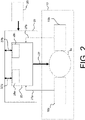
- FIG. 2 is a schematic of FMCRD 10 where motor 19 and output of the FMCRD interface with an example embodiment system 100.
- motor 19 may receive power and operative signals from a motor control cabinet 21 over motor interface 26.
- motor interface 26 may be radiation-hardened power cables that deliver electrical power, such as three-phase pulse-width modulated electrical signals, and/or information like speed controls to motor 19 in challenging environments such as operating nuclear reactor environments.
- Fine motion motor controller 20 may receive such power from a plant power source 25, including main plant electrical bus, local battery, emergency generators, or any other source of power.
- Motor controller 20 is configured to power motor interface 26 for both very fine intervals and very large power jumps.
- motor 19 may be powered to move a control blade attached to FMCRD 10 at very precise intervals, such as 3 millimeter vertical insertions or withdrawals, as well as rapid, large insertion strokes for shutdown.
- motor 19 may be a servo motor that is controllable up to 1/4 th of one revolution of a ball screw in FMCRD 10 that can self-brake and provide longterm static torque. A full revolution may equate to 12 millimeters of vertical control element movement, so positioning on an order of a few millimeters is possible. Delivery of a precise amount of power through motor interface 26 may thus achieve desired precise motor actuation and control element positioning.
- FMCRD 10 may include multiple position detectors 18a and 18b, such as precise digital transducers that can determine an exact vertical position of ball nut 12 and/or other connective structures to report an accurate position of a control element within one-thirty-sixth of a millimeter.
- Position detectors 18a and 18b may be redundant or measure position of related structures as a verification of control element positioning.
- two digital transducers as position detectors 18a and 18b may be coupled directly to a power output or shaft of motor 19 that encode rotations of the same to digitally represent motor 19 position and thus control element position. Because position detectors 18a and 18b may give digital output, informational positional signal interfaces 27a and 27b may be any connection capable of carrying digital signals, including fiber optic cable, coaxial cables, wireless signals, etc., separate or combined with motor interface 26.
- Fine motion motor controller 20 includes two channel interfaces 28a and 28b each configured to receive digital position information from an associated one of detectors 18a and 18b via positional signal interfaces 27a and 27b.
- Channel interfaces 28a and 28b may separately handle individual positional signals and control inputs so as to preserve integrity of a redundant system and allow different signals to be verified against one another without intermixing or single failure affecting both signals.
- Fine motion motor control cabinet 21 housing motor controller 20 and various interfaces and communicative connections may be local or remote from FMCRD 10. Because all components of cabinet 20 may be digital with no analog-to-digital converter, cabinet 20 may be relatively small and better hardened against an operating nuclear reactor environment.
- FIG. 3 is a schematic diagram of an example embodiment digital rod control and information system (RC&IS) 100.
- RC&IS 100 interfaces with a FMCRD 10 and fine motion motor controller 20 ( FIG. 2 ) through remote links 37a and 37b.
- RC&IS 100 may be located closer to an operator or control room, outside of containment and remote from FMCRD 10 and its motor control cabinet 21 ( FIG. 2 ), in which case remote links 37a and 37b may be any kind of digital data connection, including higher-reliability fiber optic cables or wireless connections.
- Remote links 37a and 37b together communicate dual-channel positional data from an FMCRD, such as digital positional data generated by position detectors 18a and 18b for redundant position determination of individual control elements.
- RC&IS 100 includes remote communication cabinet equipment 110 networked with an RC&IS main control logic 111 that is configured to receive input 200 from operators and other plant systems for control element operation and positioning.
- RC&IS 100 is completely digital, using microprocessors, field-programmable gate arrays, and digital communications for higher reliability and less space requirement.
- Cabinet equipment 110 may be all stored in a discreet and smaller cabinet remote or local to a control rod drive.
- cabinet equipment 110 lacking any analog-to-digital converter, may fit in a relatively small space and handle control element operations for a quarter of a nuclear core.
- all-digital RC&IS 100 is less susceptible to noise and vibration found in an operating nuclear operating environment and thus can be located anywhere in a nuclear plant and can perform self-testing and alerting functions to maintain desired operations with lower failure rates than analog equipment.
- Example embodiment RC&IS 100 is configured to handle and control an FMCRD with dual, redundant inputs to maintain operations in the case of single-channel failure, such as if a single position detector becomes unusable or signals are lost from one channel in example embodiments.
- RC&IS 100 includes two independent channels 120 and 130 in its cabinet equipment 110, each in communication with an individual position data source such as remote links 37a and 37b. Although shown in communication with a single set of remote links 37a and 37b, it is understood that multiple FMCRDs and related motor controls may be input into and controlled by cabinet equipment 110, including an entire core quadrant's worth of control drives.
- Each channel 120 and 130 independently handles distinct digital position and operation signals; however, channels 120 and 130 are also connected in order to verify and potentially replace one another.
- Bus communications 115 between all elements of channels 120 and 130 may be typical digital communications lines, including internal computer buses, motherboard connections, wired connections, or wireless connections.
- Each channel 120 and 130 includes multiplexed and redundant switches 121, 122, 124, 131, 132, and 134. Switches 122, 124, 132, and 134 may receive positional data and issue motor command signals, as well as other data, for each control rod drive associated with RC&IS 100.
- switches 121 and 122 associated with channel 120 may include connection to switches 131 and 132 of the other channel 130. Thus, if a switch fails in either channel, or if other channel components become inoperative, the operative channel and switches therein may still receive, transmit, and otherwise handle all control information.
- Each channel 120 and 130 includes a controller 123 and controller 133, respectively.
- the controllers 123 and 133 may receive, buffer, issue, and interpret control rod drive operational data.
- controllers 123 and 133 may receive rod movement commands from RC&IS control channel controllers 165 and 155, and such commands may be interpreted and sent to one or more motor controllers 20 ( FIG. 2 ) through remote links 37a and 37b.
- Motor controller 20 ( FIG. 2 ) may then provide power transmission to a motor 19 through motor interface 21 ( FIG. 2 ) to achieve desired driving, braking, and position from detectors 18a and 18b ( FIG. 2 ), interpreted for operator readout.
- controllers 123 and 133 may also perform comparison of rod movement commands from the RC&IS control logic controllers 155 and 165 to ensure that inconsistent rod movement commands do not result in rod movement.
- Switches 124 and 134 may provide redundant data links between each RC&IS logic channel controller 165 and 155, and each remote cabinet controller 123 and 133.
- Switches 122, 132, 121, and 131 may provide redundant data links between each controller 123 and 133 and multiple motor controllers 20 ( FIG 2 ).
- each controller 123 and 133 in channel 120 and 130 interfaces with an input/output switch 124 and 134 for sending and receiving operational data to operator controllers in RC&IS main control logic 111.
- main control logic 111 interfaces with several other plant safety systems and operator controls, control logic 111 is typically located in or near a control room or other plant operator station.
- Input/output switches 124 and 134 multiplex control commands and information from both channels over main logic interfaces 140 to main control logic 111.
- main control logic may include two or more main RC&IS channel controllers 165 and 155, each with two switches 161, 162, 151, and 152.
- Main logic interfaces 140 may be multiplexed to provide digital information and control data from both channels 120 and 130 to each switch 151, 152, 161, and 162. In this way, main RC&IS channel controllers 155 and 165 may have redundant switches that each have access to both channels associated with each control rod drive.
- Main RC&IS channel controllers 155 and 165 receive and implement operator feedback and input, including control element positioning commands, as well as input 200 from other plant systems, such as plant steady-state information or trip alerts. Because each main controller 155 and 165 receives redundant control and command data, and can issue redundant commands to independent channels 120 and 130, either controller 155 and 165 may be used to report on and operate all aspects of a control drive, regardless of failure of the other controller and/or of channel equipment or position reporting equipment.
- controllers 155 and 165 may verify positional and operational data received as well as operator inputs between themselves. Controllers 155 and 165 may be configured to detect discrepancies between information received from either channel 120 and 130, as well as inputs 200 or operator controls received by them both. Upon detection of a discrepancy, an operator may be notified and/or a channel may be identified as out-of-service.
- an operator or plant control system may input a very fine control element repositioning, such as 3 mm, for a single control blade, and system 100 may receive and process the move, resulting in rod movement commands to the motor controller 20 and appropriate power and signaling transmitted to motor 19 from the motor controller 20 through motor interface 26 ( FIG. 2 ).
- Position detectors 18a and 18b may then report digital, accurate rod repositioning information, which may be processed by the motor controller 20 and transmitted to the remote controllers 123 and 133, which may interpret and transmit the rod repositioning information to the main controllers 165 and 155.
- Main controllers 165 and 155 may verify this position data from both channels and thus detectors, and ensure it reflects the input command.
- channel controllers 155 and 165 are themselves digital, such analysis and notification or disregarding of bad channel data may be implemented as simple programming or hardware structuring in microprocessors of controllers 155 and 165.
- Each channel of RC&IS controller logic, 155 and 165 may contain one or more microprocessors, such as three redundant microprocessors R, S, and T each performing the same RC&IS logic computations independently and asynchronously of each other. Redundant microprocessors in each RC&IS control logic channel, 165 and 155 may ensure detectability and continuity of rod control logic functions in the presence of a single microprocessor failure.
- Example embodiment RC&IS 100 is end-to-end digital, handling data and commands received directly from digital inputs and outputs. Such digitization allows for a smaller footprint, faster analysis and action, less susceptibility to noise, vibration, heat, and radiation damage, finer motor control and monitoring, and easier handling of multiple-channel data for redundancy and verification in control rod drive operation. Further, connections among various components, such as by internal connections 115 or connections 140 between potentially remotely-situated cabinet 110 and main logic 111, may be reliable communicative connections between systems, including internal busses on motherboards, fiber optic cables, etc.
Landscapes
- Engineering & Computer Science (AREA)
- Physics & Mathematics (AREA)
- General Engineering & Computer Science (AREA)
- Plasma & Fusion (AREA)
- High Energy & Nuclear Physics (AREA)
- Chemical & Material Sciences (AREA)
- Chemical Kinetics & Catalysis (AREA)
- Monitoring And Testing Of Nuclear Reactors (AREA)
- General Physics & Mathematics (AREA)
- Automation & Control Theory (AREA)
Priority Applications (2)
| Application Number | Priority Date | Filing Date | Title |
|---|---|---|---|
| PL18763447T PL3593359T3 (pl) | 2017-03-08 | 2018-03-08 | Cyfrowe układy i sposoby sterowania o wysokiej precyzji w reaktorach jądrowych |
| EP22155689.7A EP4012724B1 (en) | 2017-03-08 | 2018-03-08 | Digital control rod drive for nuclear power plant |
Applications Claiming Priority (2)
| Application Number | Priority Date | Filing Date | Title |
|---|---|---|---|
| US15/453,195 US10910115B2 (en) | 2017-03-08 | 2017-03-08 | Digital systems and methods for high precision control in nuclear reactors |
| PCT/US2018/021431 WO2018165353A2 (en) | 2017-03-08 | 2018-03-08 | Digital systems and methods for high precision control in nuclear reactors |
Related Child Applications (2)
| Application Number | Title | Priority Date | Filing Date |
|---|---|---|---|
| EP22155689.7A Division EP4012724B1 (en) | 2017-03-08 | 2018-03-08 | Digital control rod drive for nuclear power plant |
| EP22155689.7A Division-Into EP4012724B1 (en) | 2017-03-08 | 2018-03-08 | Digital control rod drive for nuclear power plant |
Publications (3)
| Publication Number | Publication Date |
|---|---|
| EP3593359A2 EP3593359A2 (en) | 2020-01-15 |
| EP3593359A4 EP3593359A4 (en) | 2020-12-02 |
| EP3593359B1 true EP3593359B1 (en) | 2022-05-04 |
Family
ID=63445570
Family Applications (2)
| Application Number | Title | Priority Date | Filing Date |
|---|---|---|---|
| EP18763447.2A Active EP3593359B1 (en) | 2017-03-08 | 2018-03-08 | Digital systems and methods for high precision control in nuclear reactors |
| EP22155689.7A Active EP4012724B1 (en) | 2017-03-08 | 2018-03-08 | Digital control rod drive for nuclear power plant |
Family Applications After (1)
| Application Number | Title | Priority Date | Filing Date |
|---|---|---|---|
| EP22155689.7A Active EP4012724B1 (en) | 2017-03-08 | 2018-03-08 | Digital control rod drive for nuclear power plant |
Country Status (7)
| Country | Link |
|---|---|
| US (3) | US10910115B2 (pl) |
| EP (2) | EP3593359B1 (pl) |
| JP (1) | JP2020510205A (pl) |
| CA (1) | CA3055814A1 (pl) |
| MX (1) | MX2019010658A (pl) |
| PL (2) | PL4012724T3 (pl) |
| WO (1) | WO2018165353A2 (pl) |
Families Citing this family (7)
| Publication number | Priority date | Publication date | Assignee | Title |
|---|---|---|---|---|
| US10910115B2 (en) * | 2017-03-08 | 2021-02-02 | Ge-Hitachi Nuclear Energy Americas Llc | Digital systems and methods for high precision control in nuclear reactors |
| CN110398901B (zh) * | 2019-04-28 | 2023-04-18 | 北京广利核系统工程有限公司 | 核电站dcs仿真机失电仿真方法及装置 |
| CN111308935B (zh) * | 2020-02-27 | 2021-01-29 | 北京广利核系统工程有限公司 | 一种优先级管理产品自动测试装置及方法 |
| CN111292862B (zh) * | 2020-03-27 | 2021-12-17 | 江苏核电有限公司 | 基于核电厂安全重要仪表信号状态的反应堆紧急停堆方法 |
| CN117040358B (zh) * | 2023-06-09 | 2024-03-12 | 上海铼钠克数控科技有限公司 | 马达数据自动配置方法、装置、设备及可读存储介质 |
| US20250226124A1 (en) * | 2024-01-05 | 2025-07-10 | Ge-Hitachi Nuclear Energy Americas Llc | Systems and methods for limiting control element movement in nuclear power plants |
| CN118426386B (zh) * | 2024-07-02 | 2024-11-01 | 国核自仪系统工程有限公司 | 机柜状态的检测装置及其应用方法 |
Family Cites Families (37)
| Publication number | Priority date | Publication date | Assignee | Title |
|---|---|---|---|---|
| US2917445A (en) | 1956-08-07 | 1959-12-15 | Lester C Oakes | Neutronic reactor control rod drive apparatus |
| US3038847A (en) * | 1957-01-22 | 1962-06-12 | Bendix Corp | Reactor control |
| LU36080A1 (pl) * | 1957-05-16 | |||
| US3038846A (en) * | 1957-11-07 | 1962-06-12 | Martin Marietta Corp | Control rod actuator mechanism |
| GB953534A (en) * | 1959-11-09 | 1964-03-25 | Atomic Energy Authority Uk | Improvements in or relating to nuclear reactors |
| DE1140293B (de) * | 1960-01-19 | 1962-11-29 | Bofors Ab | Vorrichtung zur induktiven Stellanzeige und Servosteuerung von Kernreaktorregelstaeben |
| US3198709A (en) * | 1963-05-01 | 1965-08-03 | John W Macomber | Nuclear reactor control rod assembly with improved driving mechanism |
| CH421326A (de) * | 1964-09-10 | 1966-09-30 | Sulzer Ag | Verfahren zur Beeinflussung der Leistung eines Atomkernreaktors sowie Atomkernreaktor zur Ausübung des Verfahrens |
| US3899727A (en) * | 1968-07-22 | 1975-08-12 | Diamond Power Speciality | Plural motor control system for control rod drive mechanisms |
| US3706921A (en) * | 1968-08-08 | 1972-12-19 | Diamond Power Speciality | Reactor control including individual and group rod motor controls |
| BE838037A (fr) * | 1975-02-11 | 1976-05-14 | Commande de barre de reglage de reacteur nucleaire a la cuve sous pression | |
| US4170754A (en) * | 1975-10-16 | 1979-10-09 | Westinghouse Electric Corp. | Phase encoded digital position probe assembly |
| US4646012A (en) * | 1984-01-24 | 1987-02-24 | Westinghouse Electric Corp. | Digital, electromagnetic rod position indicator with precisely controlled transitions between digital states |
| US4629983A (en) * | 1984-10-03 | 1986-12-16 | Westinghouse Electric Corp. | Digital rod position detector system |
| US4668465A (en) * | 1984-10-26 | 1987-05-26 | Westinghouse Electric Corp. | Method and apparatus for remotely monitoring a process carried out in a containment structure |
| JPH07134191A (ja) | 1993-11-12 | 1995-05-23 | Toshiba Corp | 制御棒駆動機構の駆動装置 |
| JPH0821891A (ja) | 1994-07-08 | 1996-01-23 | Hitachi Ltd | 原子炉出力制御システムおよび制御棒位置検出装置 |
| US5832049A (en) * | 1995-03-22 | 1998-11-03 | Metro; Bernard J. | Electric circuit for selectively processing electrical signals |
| US20070153955A1 (en) | 2006-01-04 | 2007-07-05 | General Electric Company | System and method for collecting and transmitting nuclear reactor control rod position information |
| KR100841528B1 (ko) * | 2007-02-28 | 2008-06-25 | 한국원자력연구원 | 위성기어와 원주방향으로 배치된 리드스위치를 이용한회전각감지기와 이를 이용한 제어봉 위치 감지방법 |
| US20090120263A1 (en) * | 2007-11-12 | 2009-05-14 | Kabushiki Kaisha Isowa | Scorer apparatus for corrugated paperboard sheet |
| US9697916B2 (en) * | 2008-01-09 | 2017-07-04 | Analysis And Measurement Corporation | Automated system for on-line monitoring and diagnostics of rod position indication coils for nuclear power plants |
| US20100242660A1 (en) * | 2009-03-30 | 2010-09-30 | Ge-Hitachi Nuclear Energy Americas Llc | Manipulator for remote activities in a nuclear reactor vessel |
| US8670515B2 (en) | 2009-07-29 | 2014-03-11 | Westinghouse Electric Company Llc | Digital nuclear control rod control system |
| US9431137B2 (en) * | 2011-06-14 | 2016-08-30 | Analysis And Measurement Services Corporation | Systems and methods of monitoring control rods of a nuclear power plant |
| US8761329B2 (en) * | 2011-09-22 | 2014-06-24 | Westinghouse Electric Company Llc | Rod position detection apparatus and method |
| US20130315362A1 (en) * | 2012-05-25 | 2013-11-28 | Institute Of Nuclear Energy Research Atomic Energy Council, Executive Yuan | Nuclear digital instrumentation and control system |
| KR101376915B1 (ko) | 2012-07-10 | 2014-03-21 | 한국원자력연구원 | 발전용 원자로의 제어봉 제어 장치 및 방법 |
| FR2994320B1 (fr) * | 2012-07-31 | 2014-09-05 | Electricite De France | Colmatage de fissure dans une piscine d'installation nucleaire, utilisant un robot. |
| US20140369455A1 (en) | 2013-06-18 | 2014-12-18 | Analysis And Measurement Services Corporation | Data Driven Step Counter for Rod Control Systems of Nuclear Power Plants |
| RU2540441C2 (ru) * | 2013-06-26 | 2015-02-10 | Открытое акционерное общество "Всероссийский научно-исследовательский институт по эксплуатации атомных электростанций" (ОАО "ВНИИАЭС") | Указатель положения поглощающего стержня в активной зоне реактора |
| JP2015219033A (ja) | 2014-05-14 | 2015-12-07 | 株式会社日立製作所 | 制御棒操作監視システムおよび制御棒個別制御部ならびに制御棒操作監視システムの試験方法 |
| JP2015225061A (ja) * | 2014-05-30 | 2015-12-14 | 日立Geニュークリア・エナジー株式会社 | 原子炉の密閉型制御棒駆動機構を有する制御棒駆動システム |
| US10020081B2 (en) * | 2016-01-15 | 2018-07-10 | Westinghouse Electric Company Llc | Nuclear control rod position indication system |
| US10910115B2 (en) * | 2017-03-08 | 2021-02-02 | Ge-Hitachi Nuclear Energy Americas Llc | Digital systems and methods for high precision control in nuclear reactors |
| CN107833643B (zh) * | 2017-10-16 | 2019-05-24 | 中核核电运行管理有限公司 | 全数字化棒位测量装置及其方法 |
| CN117672568A (zh) * | 2023-12-07 | 2024-03-08 | 中国核动力研究设计院 | 一种反应堆长距离磁致伸缩棒位测量系统及方法 |
-
2017
- 2017-03-08 US US15/453,195 patent/US10910115B2/en active Active
-
2018
- 2018-03-08 EP EP18763447.2A patent/EP3593359B1/en active Active
- 2018-03-08 PL PL22155689.7T patent/PL4012724T3/pl unknown
- 2018-03-08 EP EP22155689.7A patent/EP4012724B1/en active Active
- 2018-03-08 MX MX2019010658A patent/MX2019010658A/es unknown
- 2018-03-08 WO PCT/US2018/021431 patent/WO2018165353A2/en not_active Ceased
- 2018-03-08 JP JP2019548989A patent/JP2020510205A/ja active Pending
- 2018-03-08 CA CA3055814A patent/CA3055814A1/en active Pending
- 2018-03-08 PL PL18763447T patent/PL3593359T3/pl unknown
-
2020
- 2020-12-22 US US17/131,200 patent/US11276504B2/en active Active
-
2022
- 2022-02-22 US US17/677,479 patent/US12417855B2/en active Active
Also Published As
| Publication number | Publication date |
|---|---|
| CA3055814A1 (en) | 2018-09-13 |
| EP3593359A4 (en) | 2020-12-02 |
| PL4012724T3 (pl) | 2024-05-20 |
| EP4012724B1 (en) | 2023-10-11 |
| EP4012724A1 (en) | 2022-06-15 |
| US10910115B2 (en) | 2021-02-02 |
| US11276504B2 (en) | 2022-03-15 |
| MX2019010658A (es) | 2020-01-13 |
| EP3593359A2 (en) | 2020-01-15 |
| US12417855B2 (en) | 2025-09-16 |
| PL3593359T3 (pl) | 2022-06-20 |
| WO2018165353A3 (en) | 2018-10-18 |
| US20220230767A1 (en) | 2022-07-21 |
| JP2020510205A (ja) | 2020-04-02 |
| US20180261339A1 (en) | 2018-09-13 |
| US20210110942A1 (en) | 2021-04-15 |
| WO2018165353A2 (en) | 2018-09-13 |
Similar Documents
| Publication | Publication Date | Title |
|---|---|---|
| US11276504B2 (en) | Digital systems and methods for high precision control in nuclear reactors | |
| JP7680601B2 (ja) | 原子炉トリップを決定するための方法 | |
| KR102873531B1 (ko) | 핵 반응기 보호 시스템 및 방법 | |
| EP3023846A1 (en) | Electromechanical drive system | |
| CN1272211A (zh) | 数字工厂保护系统 | |
| US20190010924A1 (en) | Method for controlling a machine or process with increased safety | |
| JPS6235638B2 (pl) | ||
| KR101272464B1 (ko) | 무대장치 제어시스템 | |
| EP3316260B1 (en) | Safety control system for nuclear power plant | |
| EP2945165B1 (en) | Rod control and information system and test method for rod control and information system | |
| CN1265220A (zh) | 数字化设计安全装置驱动系统 | |
| CN111693253B (zh) | 一种压力容器主螺栓孔检测装置 | |
| KR101494780B1 (ko) | 무인항공기의 전기식 구동장치와 그것의 제어방법 | |
| KR101034252B1 (ko) | 제어봉 위치 검출기의 고장 진단장치 및 그것을 포함한 노심보호 연산기 계통, 및 그 고장 진단방법 | |
| US20200227181A1 (en) | Nuclear reactor with in-vessel ex-core neutron detectors and corresponding control method | |
| CN214377699U (zh) | 核电站dcs系统架构 | |
| CN115085875B (zh) | 一种双编码器实现安全备份的装置及方法 | |
| RU2417937C1 (ru) | Устройство управления электроприводами грузоподъемного механизма | |
| KR20250111950A (ko) | 다양성이 강화된 이기종의 프로세서를 이용한 원자로 보호계통 | |
| KR101218365B1 (ko) | 프런트 패널을 구비한 단상 및 3상 moac 테스트 장치 | |
| Xu et al. | A New ALS Based PMS Design and Its Evaluations | |
| Drab et al. | System of control of A-1 nuclear reactor with moving chambers (MC system) | |
| Fennern et al. | Digital control application for the advanced boiling water reactor | |
| Sklyar et al. | Application of FPGA-based rod control system for nuclear power plants safety improvement | |
| JPS62239093A (ja) | 制御棒駆動機構位置表示システム |
Legal Events
| Date | Code | Title | Description |
|---|---|---|---|
| STAA | Information on the status of an ep patent application or granted ep patent |
Free format text: STATUS: THE INTERNATIONAL PUBLICATION HAS BEEN MADE |
|
| PUAI | Public reference made under article 153(3) epc to a published international application that has entered the european phase |
Free format text: ORIGINAL CODE: 0009012 |
|
| STAA | Information on the status of an ep patent application or granted ep patent |
Free format text: STATUS: REQUEST FOR EXAMINATION WAS MADE |
|
| 17P | Request for examination filed |
Effective date: 20190906 |
|
| AK | Designated contracting states |
Kind code of ref document: A2 Designated state(s): AL AT BE BG CH CY CZ DE DK EE ES FI FR GB GR HR HU IE IS IT LI LT LU LV MC MK MT NL NO PL PT RO RS SE SI SK SM TR |
|
| AX | Request for extension of the european patent |
Extension state: BA ME |
|
| DAV | Request for validation of the european patent (deleted) | ||
| DAX | Request for extension of the european patent (deleted) | ||
| A4 | Supplementary search report drawn up and despatched |
Effective date: 20201029 |
|
| RIC1 | Information provided on ipc code assigned before grant |
Ipc: G21C 7/14 20060101ALN20201023BHEP Ipc: G21C 7/36 20060101AFI20201023BHEP Ipc: G21D 3/00 20060101ALI20201023BHEP Ipc: G21C 17/12 20060101ALI20201023BHEP |
|
| RIC1 | Information provided on ipc code assigned before grant |
Ipc: G21C 7/14 20060101ALN20211004BHEP Ipc: G21C 17/12 20060101ALI20211004BHEP Ipc: G21D 3/00 20060101ALI20211004BHEP Ipc: G21C 7/36 20060101AFI20211004BHEP |
|
| GRAP | Despatch of communication of intention to grant a patent |
Free format text: ORIGINAL CODE: EPIDOSNIGR1 |
|
| STAA | Information on the status of an ep patent application or granted ep patent |
Free format text: STATUS: GRANT OF PATENT IS INTENDED |
|
| RIC1 | Information provided on ipc code assigned before grant |
Ipc: G21C 7/14 20060101ALN20211025BHEP Ipc: G21C 17/12 20060101ALI20211025BHEP Ipc: G21D 3/00 20060101ALI20211025BHEP Ipc: G21C 7/36 20060101AFI20211025BHEP |
|
| INTG | Intention to grant announced |
Effective date: 20211116 |
|
| GRAS | Grant fee paid |
Free format text: ORIGINAL CODE: EPIDOSNIGR3 |
|
| GRAA | (expected) grant |
Free format text: ORIGINAL CODE: 0009210 |
|
| STAA | Information on the status of an ep patent application or granted ep patent |
Free format text: STATUS: THE PATENT HAS BEEN GRANTED |
|
| AK | Designated contracting states |
Kind code of ref document: B1 Designated state(s): AL AT BE BG CH CY CZ DE DK EE ES FI FR GB GR HR HU IE IS IT LI LT LU LV MC MK MT NL NO PL PT RO RS SE SI SK SM TR |
|
| REG | Reference to a national code |
Ref country code: GB Ref legal event code: FG4D |
|
| REG | Reference to a national code |
Ref country code: CH Ref legal event code: EP |
|
| REG | Reference to a national code |
Ref country code: AT Ref legal event code: REF Ref document number: 1489993 Country of ref document: AT Kind code of ref document: T Effective date: 20220515 |
|
| REG | Reference to a national code |
Ref country code: FI Ref legal event code: FGE |
|
| REG | Reference to a national code |
Ref country code: DE Ref legal event code: R096 Ref document number: 602018034980 Country of ref document: DE |
|
| REG | Reference to a national code |
Ref country code: IE Ref legal event code: FG4D |
|
| REG | Reference to a national code |
Ref country code: SE Ref legal event code: TRGR |
|
| REG | Reference to a national code |
Ref country code: NL Ref legal event code: FP |
|
| REG | Reference to a national code |
Ref country code: LT Ref legal event code: MG9D |
|
| REG | Reference to a national code |
Ref country code: AT Ref legal event code: MK05 Ref document number: 1489993 Country of ref document: AT Kind code of ref document: T Effective date: 20220504 |
|
| PG25 | Lapsed in a contracting state [announced via postgrant information from national office to epo] |
Ref country code: PT Free format text: LAPSE BECAUSE OF FAILURE TO SUBMIT A TRANSLATION OF THE DESCRIPTION OR TO PAY THE FEE WITHIN THE PRESCRIBED TIME-LIMIT Effective date: 20220905 Ref country code: NO Free format text: LAPSE BECAUSE OF FAILURE TO SUBMIT A TRANSLATION OF THE DESCRIPTION OR TO PAY THE FEE WITHIN THE PRESCRIBED TIME-LIMIT Effective date: 20220804 Ref country code: LT Free format text: LAPSE BECAUSE OF FAILURE TO SUBMIT A TRANSLATION OF THE DESCRIPTION OR TO PAY THE FEE WITHIN THE PRESCRIBED TIME-LIMIT Effective date: 20220504 Ref country code: HR Free format text: LAPSE BECAUSE OF FAILURE TO SUBMIT A TRANSLATION OF THE DESCRIPTION OR TO PAY THE FEE WITHIN THE PRESCRIBED TIME-LIMIT Effective date: 20220504 Ref country code: GR Free format text: LAPSE BECAUSE OF FAILURE TO SUBMIT A TRANSLATION OF THE DESCRIPTION OR TO PAY THE FEE WITHIN THE PRESCRIBED TIME-LIMIT Effective date: 20220805 Ref country code: ES Free format text: LAPSE BECAUSE OF FAILURE TO SUBMIT A TRANSLATION OF THE DESCRIPTION OR TO PAY THE FEE WITHIN THE PRESCRIBED TIME-LIMIT Effective date: 20220504 Ref country code: BG Free format text: LAPSE BECAUSE OF FAILURE TO SUBMIT A TRANSLATION OF THE DESCRIPTION OR TO PAY THE FEE WITHIN THE PRESCRIBED TIME-LIMIT Effective date: 20220804 Ref country code: AT Free format text: LAPSE BECAUSE OF FAILURE TO SUBMIT A TRANSLATION OF THE DESCRIPTION OR TO PAY THE FEE WITHIN THE PRESCRIBED TIME-LIMIT Effective date: 20220504 |
|
| PG25 | Lapsed in a contracting state [announced via postgrant information from national office to epo] |
Ref country code: RS Free format text: LAPSE BECAUSE OF FAILURE TO SUBMIT A TRANSLATION OF THE DESCRIPTION OR TO PAY THE FEE WITHIN THE PRESCRIBED TIME-LIMIT Effective date: 20220504 Ref country code: LV Free format text: LAPSE BECAUSE OF FAILURE TO SUBMIT A TRANSLATION OF THE DESCRIPTION OR TO PAY THE FEE WITHIN THE PRESCRIBED TIME-LIMIT Effective date: 20220504 Ref country code: IS Free format text: LAPSE BECAUSE OF FAILURE TO SUBMIT A TRANSLATION OF THE DESCRIPTION OR TO PAY THE FEE WITHIN THE PRESCRIBED TIME-LIMIT Effective date: 20220904 |
|
| PG25 | Lapsed in a contracting state [announced via postgrant information from national office to epo] |
Ref country code: SM Free format text: LAPSE BECAUSE OF FAILURE TO SUBMIT A TRANSLATION OF THE DESCRIPTION OR TO PAY THE FEE WITHIN THE PRESCRIBED TIME-LIMIT Effective date: 20220504 Ref country code: SK Free format text: LAPSE BECAUSE OF FAILURE TO SUBMIT A TRANSLATION OF THE DESCRIPTION OR TO PAY THE FEE WITHIN THE PRESCRIBED TIME-LIMIT Effective date: 20220504 Ref country code: RO Free format text: LAPSE BECAUSE OF FAILURE TO SUBMIT A TRANSLATION OF THE DESCRIPTION OR TO PAY THE FEE WITHIN THE PRESCRIBED TIME-LIMIT Effective date: 20220504 Ref country code: EE Free format text: LAPSE BECAUSE OF FAILURE TO SUBMIT A TRANSLATION OF THE DESCRIPTION OR TO PAY THE FEE WITHIN THE PRESCRIBED TIME-LIMIT Effective date: 20220504 Ref country code: DK Free format text: LAPSE BECAUSE OF FAILURE TO SUBMIT A TRANSLATION OF THE DESCRIPTION OR TO PAY THE FEE WITHIN THE PRESCRIBED TIME-LIMIT Effective date: 20220504 |
|
| REG | Reference to a national code |
Ref country code: DE Ref legal event code: R097 Ref document number: 602018034980 Country of ref document: DE |
|
| PLBE | No opposition filed within time limit |
Free format text: ORIGINAL CODE: 0009261 |
|
| STAA | Information on the status of an ep patent application or granted ep patent |
Free format text: STATUS: NO OPPOSITION FILED WITHIN TIME LIMIT |
|
| PG25 | Lapsed in a contracting state [announced via postgrant information from national office to epo] |
Ref country code: AL Free format text: LAPSE BECAUSE OF FAILURE TO SUBMIT A TRANSLATION OF THE DESCRIPTION OR TO PAY THE FEE WITHIN THE PRESCRIBED TIME-LIMIT Effective date: 20220504 |
|
| 26N | No opposition filed |
Effective date: 20230207 |
|
| PG25 | Lapsed in a contracting state [announced via postgrant information from national office to epo] |
Ref country code: SI Free format text: LAPSE BECAUSE OF FAILURE TO SUBMIT A TRANSLATION OF THE DESCRIPTION OR TO PAY THE FEE WITHIN THE PRESCRIBED TIME-LIMIT Effective date: 20220504 |
|
| REG | Reference to a national code |
Ref country code: DE Ref legal event code: R119 Ref document number: 602018034980 Country of ref document: DE |
|
| PG25 | Lapsed in a contracting state [announced via postgrant information from national office to epo] |
Ref country code: MC Free format text: LAPSE BECAUSE OF FAILURE TO SUBMIT A TRANSLATION OF THE DESCRIPTION OR TO PAY THE FEE WITHIN THE PRESCRIBED TIME-LIMIT Effective date: 20220504 |
|
| REG | Reference to a national code |
Ref country code: CH Ref legal event code: PL |
|
| REG | Reference to a national code |
Ref country code: BE Ref legal event code: MM Effective date: 20230331 |
|
| PG25 | Lapsed in a contracting state [announced via postgrant information from national office to epo] |
Ref country code: LU Free format text: LAPSE BECAUSE OF NON-PAYMENT OF DUE FEES Effective date: 20230308 |
|
| REG | Reference to a national code |
Ref country code: IE Ref legal event code: MM4A |
|
| PG25 | Lapsed in a contracting state [announced via postgrant information from national office to epo] |
Ref country code: LI Free format text: LAPSE BECAUSE OF NON-PAYMENT OF DUE FEES Effective date: 20230331 Ref country code: IT Free format text: LAPSE BECAUSE OF FAILURE TO SUBMIT A TRANSLATION OF THE DESCRIPTION OR TO PAY THE FEE WITHIN THE PRESCRIBED TIME-LIMIT Effective date: 20220504 Ref country code: IE Free format text: LAPSE BECAUSE OF NON-PAYMENT OF DUE FEES Effective date: 20230308 Ref country code: FR Free format text: LAPSE BECAUSE OF NON-PAYMENT OF DUE FEES Effective date: 20230331 Ref country code: DE Free format text: LAPSE BECAUSE OF NON-PAYMENT OF DUE FEES Effective date: 20231003 Ref country code: CH Free format text: LAPSE BECAUSE OF NON-PAYMENT OF DUE FEES Effective date: 20230331 |
|
| PG25 | Lapsed in a contracting state [announced via postgrant information from national office to epo] |
Ref country code: BE Free format text: LAPSE BECAUSE OF NON-PAYMENT OF DUE FEES Effective date: 20230331 |
|
| PG25 | Lapsed in a contracting state [announced via postgrant information from national office to epo] |
Ref country code: BG Free format text: LAPSE BECAUSE OF FAILURE TO SUBMIT A TRANSLATION OF THE DESCRIPTION OR TO PAY THE FEE WITHIN THE PRESCRIBED TIME-LIMIT Effective date: 20220504 |
|
| PG25 | Lapsed in a contracting state [announced via postgrant information from national office to epo] |
Ref country code: BG Free format text: LAPSE BECAUSE OF FAILURE TO SUBMIT A TRANSLATION OF THE DESCRIPTION OR TO PAY THE FEE WITHIN THE PRESCRIBED TIME-LIMIT Effective date: 20220504 |
|
| PGFP | Annual fee paid to national office [announced via postgrant information from national office to epo] |
Ref country code: PL Payment date: 20250218 Year of fee payment: 8 Ref country code: CZ Payment date: 20250225 Year of fee payment: 8 |
|
| PG25 | Lapsed in a contracting state [announced via postgrant information from national office to epo] |
Ref country code: CY Free format text: LAPSE BECAUSE OF FAILURE TO SUBMIT A TRANSLATION OF THE DESCRIPTION OR TO PAY THE FEE WITHIN THE PRESCRIBED TIME-LIMIT; INVALID AB INITIO Effective date: 20180308 |
|
| PG25 | Lapsed in a contracting state [announced via postgrant information from national office to epo] |
Ref country code: HU Free format text: LAPSE BECAUSE OF FAILURE TO SUBMIT A TRANSLATION OF THE DESCRIPTION OR TO PAY THE FEE WITHIN THE PRESCRIBED TIME-LIMIT; INVALID AB INITIO Effective date: 20180308 |
|
| PG25 | Lapsed in a contracting state [announced via postgrant information from national office to epo] |
Ref country code: TR Free format text: LAPSE BECAUSE OF FAILURE TO SUBMIT A TRANSLATION OF THE DESCRIPTION OR TO PAY THE FEE WITHIN THE PRESCRIBED TIME-LIMIT Effective date: 20220504 |
|
| PGFP | Annual fee paid to national office [announced via postgrant information from national office to epo] |
Ref country code: NL Payment date: 20260219 Year of fee payment: 9 |
|
| PGFP | Annual fee paid to national office [announced via postgrant information from national office to epo] |
Ref country code: SE Payment date: 20260219 Year of fee payment: 9 |
|
| PGFP | Annual fee paid to national office [announced via postgrant information from national office to epo] |
Ref country code: GB Payment date: 20260219 Year of fee payment: 9 |
|
| PGFP | Annual fee paid to national office [announced via postgrant information from national office to epo] |
Ref country code: FI Payment date: 20260219 Year of fee payment: 9 |