EP3593065B1 - Flexibles dichtungsrohr und verfahren zur herstellung davon - Google Patents
Flexibles dichtungsrohr und verfahren zur herstellung davon Download PDFInfo
- Publication number
- EP3593065B1 EP3593065B1 EP18717221.8A EP18717221A EP3593065B1 EP 3593065 B1 EP3593065 B1 EP 3593065B1 EP 18717221 A EP18717221 A EP 18717221A EP 3593065 B1 EP3593065 B1 EP 3593065B1
- Authority
- EP
- European Patent Office
- Prior art keywords
- flexible sealing
- tube
- sealing tube
- joint
- channels
- Prior art date
- Legal status (The legal status is an assumption and is not a legal conclusion. Google has not performed a legal analysis and makes no representation as to the accuracy of the status listed.)
- Active
Links
Images


Classifications
-
- F—MECHANICAL ENGINEERING; LIGHTING; HEATING; WEAPONS; BLASTING
- F24—HEATING; RANGES; VENTILATING
- F24T—GEOTHERMAL COLLECTORS; GEOTHERMAL SYSTEMS
- F24T10/00—Geothermal collectors
- F24T10/10—Geothermal collectors with circulation of working fluids through underground channels, the working fluids not coming into direct contact with the ground
- F24T10/13—Geothermal collectors with circulation of working fluids through underground channels, the working fluids not coming into direct contact with the ground using tube assemblies suitable for insertion into boreholes in the ground, e.g. geothermal probes
- F24T10/17—Geothermal collectors with circulation of working fluids through underground channels, the working fluids not coming into direct contact with the ground using tube assemblies suitable for insertion into boreholes in the ground, e.g. geothermal probes using tubes closed at one end, i.e. return-type tubes
-
- E—FIXED CONSTRUCTIONS
- E21—EARTH OR ROCK DRILLING; MINING
- E21B—EARTH OR ROCK DRILLING; OBTAINING OIL, GAS, WATER, SOLUBLE OR MELTABLE MATERIALS OR A SLURRY OF MINERALS FROM WELLS
- E21B33/00—Sealing or packing boreholes or wells
- E21B33/10—Sealing or packing boreholes or wells in the borehole
-
- B—PERFORMING OPERATIONS; TRANSPORTING
- B29—WORKING OF PLASTICS; WORKING OF SUBSTANCES IN A PLASTIC STATE IN GENERAL
- B29C—SHAPING OR JOINING OF PLASTICS; SHAPING OF MATERIAL IN A PLASTIC STATE, NOT OTHERWISE PROVIDED FOR; AFTER-TREATMENT OF THE SHAPED PRODUCTS, e.g. REPAIRING
- B29C65/00—Joining or sealing of preformed parts, e.g. welding of plastics materials; Apparatus therefor
- B29C65/02—Joining or sealing of preformed parts, e.g. welding of plastics materials; Apparatus therefor by heating, with or without pressure
- B29C65/08—Joining or sealing of preformed parts, e.g. welding of plastics materials; Apparatus therefor by heating, with or without pressure using ultrasonic vibrations
-
- B—PERFORMING OPERATIONS; TRANSPORTING
- B29—WORKING OF PLASTICS; WORKING OF SUBSTANCES IN A PLASTIC STATE IN GENERAL
- B29C—SHAPING OR JOINING OF PLASTICS; SHAPING OF MATERIAL IN A PLASTIC STATE, NOT OTHERWISE PROVIDED FOR; AFTER-TREATMENT OF THE SHAPED PRODUCTS, e.g. REPAIRING
- B29C66/00—General aspects of processes or apparatus for joining preformed parts
- B29C66/01—General aspects dealing with the joint area or with the area to be joined
- B29C66/05—Particular design of joint configurations
- B29C66/10—Particular design of joint configurations particular design of the joint cross-sections
- B29C66/11—Joint cross-sections comprising a single joint-segment, i.e. one of the parts to be joined comprising a single joint-segment in the joint cross-section
- B29C66/112—Single lapped joints
- B29C66/1122—Single lap to lap joints, i.e. overlap joints
-
- B—PERFORMING OPERATIONS; TRANSPORTING
- B29—WORKING OF PLASTICS; WORKING OF SUBSTANCES IN A PLASTIC STATE IN GENERAL
- B29C—SHAPING OR JOINING OF PLASTICS; SHAPING OF MATERIAL IN A PLASTIC STATE, NOT OTHERWISE PROVIDED FOR; AFTER-TREATMENT OF THE SHAPED PRODUCTS, e.g. REPAIRING
- B29C66/00—General aspects of processes or apparatus for joining preformed parts
- B29C66/40—General aspects of joining substantially flat articles, e.g. plates, sheets or web-like materials; Making flat seams in tubular or hollow articles; Joining single elements to substantially flat surfaces
- B29C66/41—Joining substantially flat articles ; Making flat seams in tubular or hollow articles
- B29C66/43—Joining a relatively small portion of the surface of said articles
- B29C66/432—Joining a relatively small portion of the surface of said articles for making tubular articles or closed loops, e.g. by joining several sheets ; for making hollow articles or hollow preforms
- B29C66/4322—Joining a relatively small portion of the surface of said articles for making tubular articles or closed loops, e.g. by joining several sheets ; for making hollow articles or hollow preforms by joining a single sheet to itself
-
- F—MECHANICAL ENGINEERING; LIGHTING; HEATING; WEAPONS; BLASTING
- F16—ENGINEERING ELEMENTS AND UNITS; GENERAL MEASURES FOR PRODUCING AND MAINTAINING EFFECTIVE FUNCTIONING OF MACHINES OR INSTALLATIONS; THERMAL INSULATION IN GENERAL
- F16L—PIPES; JOINTS OR FITTINGS FOR PIPES; SUPPORTS FOR PIPES, CABLES OR PROTECTIVE TUBING; MEANS FOR THERMAL INSULATION IN GENERAL
- F16L11/00—Hoses, i.e. flexible pipes
- F16L11/04—Hoses, i.e. flexible pipes made of rubber or flexible plastics
- F16L11/042—Hoses, i.e. flexible pipes made of rubber or flexible plastics formed by bending a sheet and connecting the edges
-
- F—MECHANICAL ENGINEERING; LIGHTING; HEATING; WEAPONS; BLASTING
- F16—ENGINEERING ELEMENTS AND UNITS; GENERAL MEASURES FOR PRODUCING AND MAINTAINING EFFECTIVE FUNCTIONING OF MACHINES OR INSTALLATIONS; THERMAL INSULATION IN GENERAL
- F16L—PIPES; JOINTS OR FITTINGS FOR PIPES; SUPPORTS FOR PIPES, CABLES OR PROTECTIVE TUBING; MEANS FOR THERMAL INSULATION IN GENERAL
- F16L11/00—Hoses, i.e. flexible pipes
- F16L11/04—Hoses, i.e. flexible pipes made of rubber or flexible plastics
- F16L11/12—Hoses, i.e. flexible pipes made of rubber or flexible plastics with arrangements for particular purposes, e.g. specially profiled, with protecting layer, heated, electrically conducting
-
- F—MECHANICAL ENGINEERING; LIGHTING; HEATING; WEAPONS; BLASTING
- F16—ENGINEERING ELEMENTS AND UNITS; GENERAL MEASURES FOR PRODUCING AND MAINTAINING EFFECTIVE FUNCTIONING OF MACHINES OR INSTALLATIONS; THERMAL INSULATION IN GENERAL
- F16L—PIPES; JOINTS OR FITTINGS FOR PIPES; SUPPORTS FOR PIPES, CABLES OR PROTECTIVE TUBING; MEANS FOR THERMAL INSULATION IN GENERAL
- F16L11/00—Hoses, i.e. flexible pipes
- F16L11/22—Multi-channel hoses
-
- F—MECHANICAL ENGINEERING; LIGHTING; HEATING; WEAPONS; BLASTING
- F28—HEAT EXCHANGE IN GENERAL
- F28F—DETAILS OF HEAT-EXCHANGE AND HEAT-TRANSFER APPARATUS, OF GENERAL APPLICATION
- F28F21/00—Constructions of heat-exchange apparatus characterised by the selection of particular materials
- F28F21/06—Constructions of heat-exchange apparatus characterised by the selection of particular materials of plastics material
- F28F21/062—Constructions of heat-exchange apparatus characterised by the selection of particular materials of plastics material the heat-exchange apparatus employing tubular conduits
-
- B—PERFORMING OPERATIONS; TRANSPORTING
- B29—WORKING OF PLASTICS; WORKING OF SUBSTANCES IN A PLASTIC STATE IN GENERAL
- B29C—SHAPING OR JOINING OF PLASTICS; SHAPING OF MATERIAL IN A PLASTIC STATE, NOT OTHERWISE PROVIDED FOR; AFTER-TREATMENT OF THE SHAPED PRODUCTS, e.g. REPAIRING
- B29C65/00—Joining or sealing of preformed parts, e.g. welding of plastics materials; Apparatus therefor
- B29C65/02—Joining or sealing of preformed parts, e.g. welding of plastics materials; Apparatus therefor by heating, with or without pressure
- B29C65/04—Dielectric heating, e.g. high-frequency welding, i.e. radio frequency welding of plastic materials having dielectric properties, e.g. PVC
-
- B—PERFORMING OPERATIONS; TRANSPORTING
- B29—WORKING OF PLASTICS; WORKING OF SUBSTANCES IN A PLASTIC STATE IN GENERAL
- B29C—SHAPING OR JOINING OF PLASTICS; SHAPING OF MATERIAL IN A PLASTIC STATE, NOT OTHERWISE PROVIDED FOR; AFTER-TREATMENT OF THE SHAPED PRODUCTS, e.g. REPAIRING
- B29C65/00—Joining or sealing of preformed parts, e.g. welding of plastics materials; Apparatus therefor
- B29C65/48—Joining or sealing of preformed parts, e.g. welding of plastics materials; Apparatus therefor using adhesives, i.e. using supplementary joining material; solvent bonding
-
- B—PERFORMING OPERATIONS; TRANSPORTING
- B29—WORKING OF PLASTICS; WORKING OF SUBSTANCES IN A PLASTIC STATE IN GENERAL
- B29C—SHAPING OR JOINING OF PLASTICS; SHAPING OF MATERIAL IN A PLASTIC STATE, NOT OTHERWISE PROVIDED FOR; AFTER-TREATMENT OF THE SHAPED PRODUCTS, e.g. REPAIRING
- B29C66/00—General aspects of processes or apparatus for joining preformed parts
- B29C66/01—General aspects dealing with the joint area or with the area to be joined
- B29C66/05—Particular design of joint configurations
- B29C66/20—Particular design of joint configurations particular design of the joint lines, e.g. of the weld lines
- B29C66/24—Particular design of joint configurations particular design of the joint lines, e.g. of the weld lines said joint lines being closed or non-straight
- B29C66/242—Particular design of joint configurations particular design of the joint lines, e.g. of the weld lines said joint lines being closed or non-straight said joint lines being closed, i.e. forming closed contours
- B29C66/2424—Particular design of joint configurations particular design of the joint lines, e.g. of the weld lines said joint lines being closed or non-straight said joint lines being closed, i.e. forming closed contours being a closed polygonal chain
- B29C66/24243—Particular design of joint configurations particular design of the joint lines, e.g. of the weld lines said joint lines being closed or non-straight said joint lines being closed, i.e. forming closed contours being a closed polygonal chain forming a quadrilateral
- B29C66/24244—Particular design of joint configurations particular design of the joint lines, e.g. of the weld lines said joint lines being closed or non-straight said joint lines being closed, i.e. forming closed contours being a closed polygonal chain forming a quadrilateral forming a rectangle
-
- B—PERFORMING OPERATIONS; TRANSPORTING
- B29—WORKING OF PLASTICS; WORKING OF SUBSTANCES IN A PLASTIC STATE IN GENERAL
- B29C—SHAPING OR JOINING OF PLASTICS; SHAPING OF MATERIAL IN A PLASTIC STATE, NOT OTHERWISE PROVIDED FOR; AFTER-TREATMENT OF THE SHAPED PRODUCTS, e.g. REPAIRING
- B29C66/00—General aspects of processes or apparatus for joining preformed parts
- B29C66/40—General aspects of joining substantially flat articles, e.g. plates, sheets or web-like materials; Making flat seams in tubular or hollow articles; Joining single elements to substantially flat surfaces
- B29C66/41—Joining substantially flat articles ; Making flat seams in tubular or hollow articles
- B29C66/43—Joining a relatively small portion of the surface of said articles
- B29C66/431—Joining the articles to themselves
- B29C66/4312—Joining the articles to themselves for making flat seams in tubular or hollow articles, e.g. transversal seams
- B29C66/43121—Closing the ends of tubular or hollow single articles, e.g. closing the ends of bags
-
- B—PERFORMING OPERATIONS; TRANSPORTING
- B29—WORKING OF PLASTICS; WORKING OF SUBSTANCES IN A PLASTIC STATE IN GENERAL
- B29C—SHAPING OR JOINING OF PLASTICS; SHAPING OF MATERIAL IN A PLASTIC STATE, NOT OTHERWISE PROVIDED FOR; AFTER-TREATMENT OF THE SHAPED PRODUCTS, e.g. REPAIRING
- B29C66/00—General aspects of processes or apparatus for joining preformed parts
- B29C66/40—General aspects of joining substantially flat articles, e.g. plates, sheets or web-like materials; Making flat seams in tubular or hollow articles; Joining single elements to substantially flat surfaces
- B29C66/41—Joining substantially flat articles ; Making flat seams in tubular or hollow articles
- B29C66/43—Joining a relatively small portion of the surface of said articles
- B29C66/438—Joining sheets for making hollow-walled, channelled structures or multi-tubular articles
-
- B—PERFORMING OPERATIONS; TRANSPORTING
- B29—WORKING OF PLASTICS; WORKING OF SUBSTANCES IN A PLASTIC STATE IN GENERAL
- B29C—SHAPING OR JOINING OF PLASTICS; SHAPING OF MATERIAL IN A PLASTIC STATE, NOT OTHERWISE PROVIDED FOR; AFTER-TREATMENT OF THE SHAPED PRODUCTS, e.g. REPAIRING
- B29C66/00—General aspects of processes or apparatus for joining preformed parts
- B29C66/50—General aspects of joining tubular articles; General aspects of joining long products, i.e. bars or profiled elements; General aspects of joining single elements to tubular articles, hollow articles or bars; General aspects of joining several hollow-preforms to form hollow or tubular articles
- B29C66/51—Joining tubular articles, profiled elements or bars; Joining single elements to tubular articles, hollow articles or bars; Joining several hollow-preforms to form hollow or tubular articles
- B29C66/52—Joining tubular articles, bars or profiled elements
- B29C66/522—Joining tubular articles
- B29C66/5227—Joining tubular articles for forming multi-tubular articles by longitudinally joining elementary tubular articles wall-to-wall (e.g. joining the wall of a first tubular article to the wall of a second tubular article) or for forming multilayer tubular articles
-
- B—PERFORMING OPERATIONS; TRANSPORTING
- B29—WORKING OF PLASTICS; WORKING OF SUBSTANCES IN A PLASTIC STATE IN GENERAL
- B29C—SHAPING OR JOINING OF PLASTICS; SHAPING OF MATERIAL IN A PLASTIC STATE, NOT OTHERWISE PROVIDED FOR; AFTER-TREATMENT OF THE SHAPED PRODUCTS, e.g. REPAIRING
- B29C66/00—General aspects of processes or apparatus for joining preformed parts
- B29C66/50—General aspects of joining tubular articles; General aspects of joining long products, i.e. bars or profiled elements; General aspects of joining single elements to tubular articles, hollow articles or bars; General aspects of joining several hollow-preforms to form hollow or tubular articles
- B29C66/61—Joining from or joining on the inside
-
- B—PERFORMING OPERATIONS; TRANSPORTING
- B29—WORKING OF PLASTICS; WORKING OF SUBSTANCES IN A PLASTIC STATE IN GENERAL
- B29C—SHAPING OR JOINING OF PLASTICS; SHAPING OF MATERIAL IN A PLASTIC STATE, NOT OTHERWISE PROVIDED FOR; AFTER-TREATMENT OF THE SHAPED PRODUCTS, e.g. REPAIRING
- B29C66/00—General aspects of processes or apparatus for joining preformed parts
- B29C66/70—General aspects of processes or apparatus for joining preformed parts characterised by the composition, physical properties or the structure of the material of the parts to be joined; Joining with non-plastics material
- B29C66/71—General aspects of processes or apparatus for joining preformed parts characterised by the composition, physical properties or the structure of the material of the parts to be joined; Joining with non-plastics material characterised by the composition of the plastics material of the parts to be joined
-
- B—PERFORMING OPERATIONS; TRANSPORTING
- B29—WORKING OF PLASTICS; WORKING OF SUBSTANCES IN A PLASTIC STATE IN GENERAL
- B29C—SHAPING OR JOINING OF PLASTICS; SHAPING OF MATERIAL IN A PLASTIC STATE, NOT OTHERWISE PROVIDED FOR; AFTER-TREATMENT OF THE SHAPED PRODUCTS, e.g. REPAIRING
- B29C66/00—General aspects of processes or apparatus for joining preformed parts
- B29C66/70—General aspects of processes or apparatus for joining preformed parts characterised by the composition, physical properties or the structure of the material of the parts to be joined; Joining with non-plastics material
- B29C66/72—General aspects of processes or apparatus for joining preformed parts characterised by the composition, physical properties or the structure of the material of the parts to be joined; Joining with non-plastics material characterised by the structure of the material of the parts to be joined
- B29C66/729—Textile or other fibrous material made from plastics
- B29C66/7292—Textile or other fibrous material made from plastics coated
-
- B—PERFORMING OPERATIONS; TRANSPORTING
- B29—WORKING OF PLASTICS; WORKING OF SUBSTANCES IN A PLASTIC STATE IN GENERAL
- B29C—SHAPING OR JOINING OF PLASTICS; SHAPING OF MATERIAL IN A PLASTIC STATE, NOT OTHERWISE PROVIDED FOR; AFTER-TREATMENT OF THE SHAPED PRODUCTS, e.g. REPAIRING
- B29C66/00—General aspects of processes or apparatus for joining preformed parts
- B29C66/70—General aspects of processes or apparatus for joining preformed parts characterised by the composition, physical properties or the structure of the material of the parts to be joined; Joining with non-plastics material
- B29C66/73—General aspects of processes or apparatus for joining preformed parts characterised by the composition, physical properties or the structure of the material of the parts to be joined; Joining with non-plastics material characterised by the intensive physical properties of the material of the parts to be joined, by the optical properties of the material of the parts to be joined, by the extensive physical properties of the parts to be joined, by the state of the material of the parts to be joined or by the material of the parts to be joined being a thermoplastic or a thermoset
- B29C66/731—General aspects of processes or apparatus for joining preformed parts characterised by the composition, physical properties or the structure of the material of the parts to be joined; Joining with non-plastics material characterised by the intensive physical properties of the material of the parts to be joined, by the optical properties of the material of the parts to be joined, by the extensive physical properties of the parts to be joined, by the state of the material of the parts to be joined or by the material of the parts to be joined being a thermoplastic or a thermoset characterised by the intensive physical properties of the material of the parts to be joined
- B29C66/7318—Permeability to gases or liquids
- B29C66/73185—Permeability to gases or liquids non-permeable
- B29C66/73187—Permeability to gases or liquids non-permeable to liquids
-
- B—PERFORMING OPERATIONS; TRANSPORTING
- B29—WORKING OF PLASTICS; WORKING OF SUBSTANCES IN A PLASTIC STATE IN GENERAL
- B29C—SHAPING OR JOINING OF PLASTICS; SHAPING OF MATERIAL IN A PLASTIC STATE, NOT OTHERWISE PROVIDED FOR; AFTER-TREATMENT OF THE SHAPED PRODUCTS, e.g. REPAIRING
- B29C66/00—General aspects of processes or apparatus for joining preformed parts
- B29C66/70—General aspects of processes or apparatus for joining preformed parts characterised by the composition, physical properties or the structure of the material of the parts to be joined; Joining with non-plastics material
- B29C66/73—General aspects of processes or apparatus for joining preformed parts characterised by the composition, physical properties or the structure of the material of the parts to be joined; Joining with non-plastics material characterised by the intensive physical properties of the material of the parts to be joined, by the optical properties of the material of the parts to be joined, by the extensive physical properties of the parts to be joined, by the state of the material of the parts to be joined or by the material of the parts to be joined being a thermoplastic or a thermoset
- B29C66/739—General aspects of processes or apparatus for joining preformed parts characterised by the composition, physical properties or the structure of the material of the parts to be joined; Joining with non-plastics material characterised by the intensive physical properties of the material of the parts to be joined, by the optical properties of the material of the parts to be joined, by the extensive physical properties of the parts to be joined, by the state of the material of the parts to be joined or by the material of the parts to be joined being a thermoplastic or a thermoset characterised by the material of the parts to be joined being a thermoplastic or a thermoset
- B29C66/7392—General aspects of processes or apparatus for joining preformed parts characterised by the composition, physical properties or the structure of the material of the parts to be joined; Joining with non-plastics material characterised by the intensive physical properties of the material of the parts to be joined, by the optical properties of the material of the parts to be joined, by the extensive physical properties of the parts to be joined, by the state of the material of the parts to be joined or by the material of the parts to be joined being a thermoplastic or a thermoset characterised by the material of the parts to be joined being a thermoplastic or a thermoset characterised by the material of at least one of the parts being a thermoplastic
- B29C66/73921—General aspects of processes or apparatus for joining preformed parts characterised by the composition, physical properties or the structure of the material of the parts to be joined; Joining with non-plastics material characterised by the intensive physical properties of the material of the parts to be joined, by the optical properties of the material of the parts to be joined, by the extensive physical properties of the parts to be joined, by the state of the material of the parts to be joined or by the material of the parts to be joined being a thermoplastic or a thermoset characterised by the material of the parts to be joined being a thermoplastic or a thermoset characterised by the material of at least one of the parts being a thermoplastic characterised by the materials of both parts being thermoplastics
-
- B—PERFORMING OPERATIONS; TRANSPORTING
- B29—WORKING OF PLASTICS; WORKING OF SUBSTANCES IN A PLASTIC STATE IN GENERAL
- B29C—SHAPING OR JOINING OF PLASTICS; SHAPING OF MATERIAL IN A PLASTIC STATE, NOT OTHERWISE PROVIDED FOR; AFTER-TREATMENT OF THE SHAPED PRODUCTS, e.g. REPAIRING
- B29C66/00—General aspects of processes or apparatus for joining preformed parts
- B29C66/80—General aspects of machine operations or constructions and parts thereof
- B29C66/81—General aspects of the pressing elements, i.e. the elements applying pressure on the parts to be joined in the area to be joined, e.g. the welding jaws or clamps
- B29C66/814—General aspects of the pressing elements, i.e. the elements applying pressure on the parts to be joined in the area to be joined, e.g. the welding jaws or clamps characterised by the design of the pressing elements, e.g. of the welding jaws or clamps
- B29C66/8141—General aspects of the pressing elements, i.e. the elements applying pressure on the parts to be joined in the area to be joined, e.g. the welding jaws or clamps characterised by the design of the pressing elements, e.g. of the welding jaws or clamps characterised by the surface geometry of the part of the pressing elements, e.g. welding jaws or clamps, coming into contact with the parts to be joined
- B29C66/81427—General aspects of the pressing elements, i.e. the elements applying pressure on the parts to be joined in the area to be joined, e.g. the welding jaws or clamps characterised by the design of the pressing elements, e.g. of the welding jaws or clamps characterised by the surface geometry of the part of the pressing elements, e.g. welding jaws or clamps, coming into contact with the parts to be joined comprising a single ridge, e.g. for making a weakening line; comprising a single tooth
-
- B—PERFORMING OPERATIONS; TRANSPORTING
- B29—WORKING OF PLASTICS; WORKING OF SUBSTANCES IN A PLASTIC STATE IN GENERAL
- B29C—SHAPING OR JOINING OF PLASTICS; SHAPING OF MATERIAL IN A PLASTIC STATE, NOT OTHERWISE PROVIDED FOR; AFTER-TREATMENT OF THE SHAPED PRODUCTS, e.g. REPAIRING
- B29C66/00—General aspects of processes or apparatus for joining preformed parts
- B29C66/80—General aspects of machine operations or constructions and parts thereof
- B29C66/83—General aspects of machine operations or constructions and parts thereof characterised by the movement of the joining or pressing tools
- B29C66/832—Reciprocating joining or pressing tools
- B29C66/8322—Joining or pressing tools reciprocating along one axis
- B29C66/83221—Joining or pressing tools reciprocating along one axis cooperating reciprocating tools, each tool reciprocating along one axis
-
- B—PERFORMING OPERATIONS; TRANSPORTING
- B29—WORKING OF PLASTICS; WORKING OF SUBSTANCES IN A PLASTIC STATE IN GENERAL
- B29C—SHAPING OR JOINING OF PLASTICS; SHAPING OF MATERIAL IN A PLASTIC STATE, NOT OTHERWISE PROVIDED FOR; AFTER-TREATMENT OF THE SHAPED PRODUCTS, e.g. REPAIRING
- B29C66/00—General aspects of processes or apparatus for joining preformed parts
- B29C66/80—General aspects of machine operations or constructions and parts thereof
- B29C66/83—General aspects of machine operations or constructions and parts thereof characterised by the movement of the joining or pressing tools
- B29C66/836—Moving relative to and tangentially to the parts to be joined, e.g. transversely to the displacement of the parts to be joined, e.g. using a X-Y table
-
- B—PERFORMING OPERATIONS; TRANSPORTING
- B29—WORKING OF PLASTICS; WORKING OF SUBSTANCES IN A PLASTIC STATE IN GENERAL
- B29L—INDEXING SCHEME ASSOCIATED WITH SUBCLASS B29C, RELATING TO PARTICULAR ARTICLES
- B29L2031/00—Other particular articles
- B29L2031/18—Heat-exchangers or parts thereof
-
- E—FIXED CONSTRUCTIONS
- E21—EARTH OR ROCK DRILLING; MINING
- E21B—EARTH OR ROCK DRILLING; OBTAINING OIL, GAS, WATER, SOLUBLE OR MELTABLE MATERIALS OR A SLURRY OF MINERALS FROM WELLS
- E21B34/00—Valve arrangements for boreholes or wells
- E21B34/02—Valve arrangements for boreholes or wells in well heads
-
- F—MECHANICAL ENGINEERING; LIGHTING; HEATING; WEAPONS; BLASTING
- F28—HEAT EXCHANGE IN GENERAL
- F28F—DETAILS OF HEAT-EXCHANGE AND HEAT-TRANSFER APPARATUS, OF GENERAL APPLICATION
- F28F2250/00—Arrangements for modifying the flow of the heat exchange media, e.g. flow guiding means; Particular flow patterns
- F28F2250/04—Communication passages between channels
-
- F—MECHANICAL ENGINEERING; LIGHTING; HEATING; WEAPONS; BLASTING
- F28—HEAT EXCHANGE IN GENERAL
- F28F—DETAILS OF HEAT-EXCHANGE AND HEAT-TRANSFER APPARATUS, OF GENERAL APPLICATION
- F28F2255/00—Heat exchanger elements made of materials having special features or resulting from particular manufacturing processes
- F28F2255/02—Flexible elements
-
- Y—GENERAL TAGGING OF NEW TECHNOLOGICAL DEVELOPMENTS; GENERAL TAGGING OF CROSS-SECTIONAL TECHNOLOGIES SPANNING OVER SEVERAL SECTIONS OF THE IPC; TECHNICAL SUBJECTS COVERED BY FORMER USPC CROSS-REFERENCE ART COLLECTIONS [XRACs] AND DIGESTS
- Y02—TECHNOLOGIES OR APPLICATIONS FOR MITIGATION OR ADAPTATION AGAINST CLIMATE CHANGE
- Y02E—REDUCTION OF GREENHOUSE GAS [GHG] EMISSIONS, RELATED TO ENERGY GENERATION, TRANSMISSION OR DISTRIBUTION
- Y02E10/00—Energy generation through renewable energy sources
- Y02E10/10—Geothermal energy
Definitions
- the present disclosure pertains to a flexible sealing tube adapted to be installed in and extend along a bore in the ground for use in a system for exchanging of energy with the ground. Moreover, the present disclosure also relates to a method of producing the flexible sealing tube.
- the layers may constitute of different types of rock, but there may also be layers of sand or gravel of different fraction which may reduce the strength of the walls of the borehole.
- the borehole may therefore risk bringing unwanted particles into the borehole with the ground water flowing in the ground and particularly in the smaller particle comprising layers or even collapse of the walls of the bore hole.
- the amount of energy which may be extracted from the ground depends on several factors, such as the extension of the bore, the temperature of the surrounding ground water and/or the earth crust, the ground water transporting amount around the borehole and the capacity of the installed system for extraction of temperature differences between the surrounding ground and the circulating liquid in the tubing system.
- the present disclosure pertains to a flexible sealing tube adapted to be installed in and extend along a bore in the ground for use in a system for exchanging of energy with the ground.
- the flexible sealing tube comprises a first tube end to be installed at an inner part of the bore.
- the flexible sealing tube is closed in the first tube end and further comprises a first channel and a second channel extending in a longitudinal direction of the flexible sealing tube.
- the first and second channels are in fluid connection with each other and the first and second channels are formed by folding a flexible sealing material to form a tube.
- Said flexible sealing tube comprises a longitudinally extending first joint, said first and second channels being provided on opposite sides of said longitudinally extending first joint.
- first and the second channels are formed by the flexible sealing tube and the walls of the channels simultaneously are the walls of the flexible sealing tube provides an effective energy exchange between the ground and the liquid provided in the flexible sealing tube as the liquid is separated from the surrounding ground only by the flexible sealing tube, thus providing an efficient energy transfer between the liquid in the flexible sealing tube and the surrounding ground.
- the flexible sealing tube filling up the bore also constitutes the channels, the closed system enables a large liquid flow which may deliver a large quantity of heated/cooled liquid.
- flexible sealing tube herein is meant a tube formed from a flexible material which material provides a water-impermeable barrier.
- a flexible material in the meaning of this disclosure is a material which has an inherent capability of folding, preferably to the extent of being doubled, such that material on either side of a fold is capable of lying against the material of the opposite side of the fold. The flexibility is not only utilized for the production of the flexible sealing tube itself, but is also utilised for adaptation to the shape of the walls of the bore in the ground when installed. When the flexible sealing tube is provided with joints, such joints should be water-impermeable as well to maintain the water-impermeable barrier of the flexible sealing tube.
- the increase in efficacy of the system may lead to that the depth of the bore can be reduced, resulting in a simplified and more cost efficient solution.
- the construction of the flexible sealing tube providing the channel system in the system for exchange of energy with the ground also simplifies the system as the construction requires few components compared to known systems.
- the flexible sealing may also be conveniently stored and transported as there are no rigid component taking up a lot of space and which may be cumbersome to transport and handle.
- the flexible sealing tube may be rolled up after manufacturing and conveniently stored and transported in rolled up form.
- first and second channel each comprises a first end portion.
- the first end portions may then be located adjacent to the first tube end, and the first and second channels may be in fluid connection with each other in their first end portions.
- the extension of the liquid transport extends from the bore opening to the first end of the flexible sealing tube and thus provides a maximized energy exchange with the ground and a utilization of the entire length of the tube for the liquid flow.
- the flexible sealing tube may furthermore comprise a second tube end.
- the second tube end may be provided at the level of, or slightly beneath, the bore opening. As the ground water level is often a few meter below ground level the bore may need reinforcement, such as in the form of a steel ring, to compensate for the lack of pressure from the ground water balancing the pressure within the well.
- the second tube end may be provided beneath the steel ring or overlapping with the steel ring.
- the first and second channel each comprises a second end portion, the second end portions being located adjacent to the second tube end.
- the second end portions of the first and second channels may each be adapted to be operatively connected to a heat exchanging device.
- the second tube end is closed and the first and second channels are operatively connected to the heat exchanging device via a respective first and second inlet/outlet opening provided in the flexible sealing tube.
- the second tube end may thus, via the first and second inlet/outlet openings, be connected to the heat exchanging device.
- Each of the inlet/outlet openings may be provided with coupling means allowing connection with tubes for fluidly connecting the flexible sealing tube with the heat exchanging device.
- At least one of the inlet/outlet openings is provided with a valve.
- both of the inlet/outlet openings are provided with a respective valve.
- the flexible sealing tube comprises a longitudinally extending first joint, and the first and second channels are provided on opposite sides of the longitudinally extending joint.
- Such a flexible sealing tube wherein the first and second channels are formed by a longitudinally extending first joint in the flexible sealing tube provides for a simple and convenient system which is easy to roll up, store, handle and transport.
- the walls of the first and second channels of the flexible sealing tube in use are adapted to partially support each other, preferably to lie against each other, and to partially lie against walls of the bore in the ground.
- the walls of the first and second channels may consequently be in contact with each other in use of the flexible sealing tube.
- they may partially lie in close contact and along each other and being separated by e.g. an insulating layer.
- an insulation layer may be used to limit the energy exchange between the first and second channels of the flexible sealing tube.
- Such a flexible sealing tube fills up the majority of the cross-section of the bore in the ground, preferably substantially all of the cross-section, for maximising the contact with the ground for efficient energy exchange.
- the parts of the walls of the first and second channels which lie against each other also support and stabilize the flexible sealing tube when installed
- the longitudinally extending first joint is formed by welding, such as by high frequency welding, gluing or the like.
- the fluid communication between the first and second channels is formed by an opening provided between the first and second channel.
- the opening between the first and second channels is located in an area in which the first and second channels are joined together by a second joint and the opening is completely surrounded by the second joint.
- the flexible sealing tube comprises a thermoplastic material, such as for example polyamide or polyester.
- the flexible sealing tube comprises a textile material, such as a liquid impermeable textile material.
- the textile material may be a woven material, such as a woven material made from yarn of thermoplastic fibers.
- the thermoplastic fibers may be made from synthetic thermoplastic material.
- the woven material may be coated with a coating material to provide a liquid impermeable material. Such coating may for example be a silicon or polyurethane coating.
- the flexible sealing tube may however also comprise or be made of a nonwoven material or a plastic film made from a thermoplastic material.
- the nonwoven material may be coated with a coating material to provide a liquid impermeable material, such coating may for example be a silicon or polyurethane coating, or a laminate of a plastic film and the nonwoven material.
- the present disclosure relates to a method for manufacturing a flexible sealing tube adapted to be installed in and extend along a bore in the ground for use in a system for exchanging of energy with the ground, comprising the step of;
- first and second channels are formed by a longitudinally extending first joint, provides for a simple and cost efficient method of producing a flexible sealing tube instead of providing separate components
- step c) comprises the steps of;
- the joined area formed by the second joint between the first and second channel walls is formed by welding, such as high frequency welding.
- step c1) comprises that the joined welded area is formed by inserting welding means, such as electrodes, in the first and second channel and welding together the first and second channel walls to form the joined welded area.
- welding means such as electrodes
- step b) of forming a first joint will simultaneously seal the tube-shaped material while forming the longitudinally extending first joint forming the first and the second longitudinally extending channel.
- the method further comprises a step d) of joining the first tube end with a third joint.
- step d) comprises forming the first tube end to provide the first tube end with a tapering shape.
- the method comprises a step e) of joining the second tube end with a fourth joint.
- the step e) may be carried out before or after step c) or d).
- the method comprises a step f) of providing in the second tube end of the flexible sealing tube a first inlet/outlet opening to the first channel and a second inlet/outlet opening to the second channel.
- Each of the inlet/outlet openings providing fluid connection to the respective channel and may be provided with coupling means allowing connection with tubes for fluidly connecting the flexible sealing tube with the heat exchanging device.
- Fig. 1a illustrates a system for exchanging of energy 1 with the ground 3.
- the system 1 comprises a flexible sealing tube 2 installed in and extending along a bore in a ground 3.
- the bore is a generally vertical bore in the ground.
- the bore is used as energy well for extracting, for example, heat for heating a house (not shown) or for storing heat in the ground 3.
- Such bores are most often vertical, but may however also be an inclined bore or a horizontally extending bore.
- the ground 3 is constituted of soil instead of rock.
- the rock may also penetrate the soil up to the ground surface, but it may also be present hundreds of meters down from the ground surface. Under normal conditions the rock may be found somewhere between a few up to ten to twenty meters underneath the ground level.
- the flexible sealing tube according to the present disclosure may be used under all of these conditions.
- the flexible sealing tube 2 when installed in the bore in the ground 3 and filled with a liquid, will seal against the perimeter of the bore such that the flexible sealing tube 2 seals of different levels along the bore and the risk for contamination between different levels along the bore is reduced.
- the flexible sealing tube 2 comprises a closed first tube end 4 installed at the inner part of the bore and a second tube end 5 close to the mouth of the bore at the ground level.
- a casing 28 normally a concrete casing, may be installed to shield the bore from the earth layers.
- the vertical upper end of the casing may be shielded with a casing cover or seal.
- the flexible sealing tube 2 furthermore forms a first channel 6 and a second channel 7 extending in a longitudinal direction (L) of the flexible sealing tube 2.
- the first and second channels 6, 7 are in fluid connection with each other via an opening 14 formed between the first and second channels 6, 7.
- the first and second channel 6, 7 each comprises a respective first end portion 6a, 7a located adjacent to the first tube end 4.
- the first and second channels 6, 7 are in fluid connection with each other in their respective first end portions 6a, 7a.
- the first and second channel 6, 7 each comprises a respective second end portion 6b, 7b located adjacent to the second tube end 5.
- the second end 5 is connected to piping's leading into a heat exchanging device 8.
- the second end portions 6b, 7b of the first and second channels 6, 7 are each adapted to be operatively connected to a heat exchanging device 8, such as a heat pump system.
- the first channel 6 is connected to the heat exchanging device 8 via a first inlet/outlet opening 9 and the second channel 7 is connected to the heat exchanging device 8 via a second inlet/outlet opening 10.
- Each of the inlet/outlet openings 9,10 are provided in the wall of the flexible sealing tube 2.
- the first and the second inlet/outlet openings 9,10 are provided with a respective valve 11, 12 for controlling the flow and pressure of the liquid in the system for exchanging of energy 1.
- the first and second inlet/outlet openings 9,10 are connected to the heat exchanging device 8, such as a heat pump, via steel or plastic pipes 22,23.
- the heat pump In order to extract energy from the energy well, the heat pump circulates the liquid in the system 1 and the pipe 22 supplies liquid into the first channel 6.
- the over pressure produced by the heat pump transports the liquid from the first channel 6 and into the second channel 7, via the opening 14 positioned close to the first tube end 4 of the flexible sealing tube 2.
- the opening 14 should be positioned as close to the first tube end 4 as possible.
- the second channel 7 returns the liquid to the heat pump system 8 where the heat energy absorbed by the liquid is extracted and may be transferred to a heating system of a house.
- the liquid utilized in the system 1 conventionally comprises water and an anti-freezing agent, however it is also possible to use only water or other liquids.
- the pressure exerted by the liquid in the flexible sealing tube 2 will press the outer walls of the flexible sealing tube 2 against the walls of the bore which effectively closes off water surrounding the flexible sealing tube 2 within the bore from penetrating from one vertical level within the bore to another to another vertical level within the bore.
- the system for extracting energy 1 from the ground 3 may also be driven in the reverse direction, such as if the system is to be utilized for storing energy from the ground 3 or to cool the liquid in a cooling system for buildings or other applications.
- the flexible sealing tube 2 is preferably made of a thermoplastic textile material, such as for example a woven material made of polyamide or polyester.
- the material should be substantially water impermeable and sealable, preferable weldable. Other sealing methods may be used if working adequately with the material of the flexible sealing tube 2.
- the woven material may be made from synthetic thermoplastic fiber yarns, such as for example from polyamide or polyester.
- the woven material may be coated with a coating material to provide a liquid impermeable material, the coating may be a silicon or polyurethane coating.
- the material may for example have a weight, including coating, of from 500 g/m 2 to 1250 g/m 2 .
- the flexible sealing tube 2 is at its first end 4 sealed with a third joint 18 (shown in fig. 1b ) so that no water from the ground penetrates the flexible sealing tube 2.
- the third joint 18 is thus a water-impermeable joint.
- the joints are preferably provided by welding a continuous weld seam.
- the flexible sealing tube 2 is provided with a hole 20 in the end portion for attachment of a load 21 to facilitate lowering of the flexible sealing tube 2 into the bore in the ground 3.
- the channels 6 and 7 are, in the second end 5, connected to a top head being the connecting device between the channels 6,7 and piping 22,23.
- the length of the flexible sealing tube 2 is adapted to extend substantially all the way up the mouth of the bore at the ground level.
- One reason why it may be suitable for the flexible sealing tube 2 to extend slightly beneath the level of the mouth of the bore is that it prevents undesirable manipulation or damaging of the flexible sealing tube 2.
- a suitable level of the second tube end 5 may be adjacent to the transition between the frost level and the frost-free level, which in Sweden corresponds to about 1-2 meters below ground level.
- the part of the bore situated above the second tube end 5, but beneath the mouth of the bore is sealed and may for example be covered with earth. It should be noted that normally all arrangements and fittings for a heat exchange system is concealed underground 3 to prohibit manipulation or weather impacts.
- the flexible sealing tube 2 may typically have a length of 100 - 200 meters, to extend substantially all the way down to the bottom of the bore.
- the length of the flexible sealing tube 2 may be adjusted to fit the intended bore, the flexible sealing tube 2 may thus be both shorter and longer depending on the requirements of the specific energy well.
- the diameter of the flexible sealing tube may be from 10 to 25 cm, which should correspond to the diameter of the bore in which the flexible sealing should be installed.
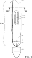
- Fig. 1b is a cross-sectional view of the flexible sealing tube 2 shown in fig. 1a .
- the fluid connection between the first and the second channels 6, 7 is provided by the openings in the first and second channel walls 16,17 which are folded against each other such that the openings located in each of the first and second channel walls 16,17 forms the fluidly connecting opening 14.
- the first and second channel walls 16,17 are joined with a second joint 15 over a joined area and the opening 14 is punched out within the joined area in each of the first and second channel wall 16,17 such that the opening 14 is completely surrounded by the second joint 15.
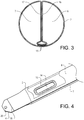
- Fig. 2 which is a perspective view of the flexible sealing tube 2 in the first end portion part.
- the joint 15 is a water-impermeable joint forming a water-impermeable seal around the opening 14.
- Fig. 3 is a cross-sectional view taken along lines III-III in figure 2 and illustrates the flexible sealing tube 2 with a longitudinally extending first joint 13 and the first and second channels 6, 7 provided on opposite sides of the longitudinally extending first joint 13.
- the flexible sealing tube 2 is folded over the longitudinally extending first joint 13 with the first and the second channel walls 16, 17 in contact with each other.
- the longitudinally extending first joint 13 may be formed by sealing through for instance gluing or welding, for instance with high frequency weld to form a continuous joint.
- the joints provided to the flexible sealing tube 2 is preferable performed by means of the same sealing method, preferably by the same welding method.
- the width of each of the joints is preferably within the range of from 10 to 75 mm.
- the width of the joints 13 and/or 15 may be around from 15 to 35 mm, however the width may from around from around 45 to 75 mm to strengthen critical parts.
- the flexible sealing tube 2 is adapted to be installed in and extend along a bore in a ground 3 for use in a system for exchanging of energy 1 with the ground 3.
- the flexible sealing tube 2 comprises a first tube end 4 to be installed at an inner part of the bore.
- the flexible sealing tube 2 is closed in the first tube end 4, and comprises further a first channel 6 and a second channel 7 extending in a longitudinal direction L of the flexible sealing tube 2.
- the first and second channels 6, 7 are in fluid connection with each other, and are formed by the flexible sealing tube 2.
- Fig. 4 is a cutaway view of the first end portion 6a of the flexible sealing tube 2, showing the first channel 6 and the opening 14 located between the first and second channel walls 16,17 and the joint 15 surrounding the opening 14.
- the width of the joint 15 is between 15 and 55 mm.
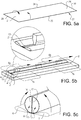
- a flexible sealing tube 2 as shown in fig. 1-4 may be produced by the method illustrated in figs. 5a-k .
- the method involves folding a flexible sealing material 2' shown in fig. 5a into a tube-shaped flexible sealing material 2' having a first end 4' and a second end 5' as shown in fig. 5b .
- the flexible sealing material has a first side 26 and a second side 27, longitudinally opposing first and second side edges 24, 25 and transverse opposing side edges 29, 30.
- the opposing longitudinal side edges 24, 25 of the flexible sealing material 2' are folded over the first side 26 of the flexible sealing material 2' such that they overlap each other and that a tube-shaped flexible sealing material 2' having a longitudinal direction L is formed.
- the longitudinal side edges 24, 25 may also extend side by side in a abutting relationship when the flexible sealing material 2' has been folded.
- a longitudinally extending first joint 13 is then formed, as illustrated in fig. 5b , between the first and the second transverse side edges 29, 30, sealing the longitudinal side edges 24, 25 of the tube-shaped flexible sealing material 2' to the first side 26 of the flexible sealing material 2' such that a flexible sealing tube 2 is provided comprising a first and a second longitudinally extending channel 6, 7 separated by the longitudinally extending first joint 13.
- the first and second longitudinally extending channels 6, 7 each comprise a first end portion 6a, 7a and a second end portion 6b, 7b.
- the flexible sealing tube 2 may be provided in pre-sealed or in ready-made tube-shaped form prior to the step illustrated in fig. 5b of providing a longitudinally extending first joint 13 extending from the first transverse side edge 29 to the second transverse side edge 30.
- the opposing longitudinal side edges 24, 25 of the flexible sealing material 2' are folded over the first side 26 of the flexible sealing material 2' such that they do not overlap each other and that they do not end up in abutment with each other, but that they are positioned in opposing relationship at a distance from each other such that a tube-shaped flexible sealing material 2' having a longitudinal direction L is thus formed.
- the step illustrated in fig. 5b may then take place either in a single step or in in substeps, either in parallel or in consecutive order.
- Each opposing longitudinal side edges 24, 25 may be sealed by a common seal, or by each one their own seal. In the latter case the longitudinally extending first joint 13 is made up by two combined seals.
- Fig. 5c illustrates folding of the flexible sealing tube 2 over the longitudinally extending first joint 13 such that the flexible sealing tube 2 is in a double folded configuration.
- the first channel 6 has a first channel wall 16 and the second channel 7 has a second channel wall 17 as shown in fig. 5c .
- the flexible sealing tube 2 may of course be folded differently, such that for example the longitudinally extending first joint 13 is located centrically in the flexible sealing tube 2.
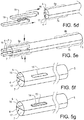
- Fig. 5d illustrates introducing welding means 19, such as electrodes, in the first and second channel 6, 7 in a first tube end 4 and fig. 5e illustrates pressing together of the welding means 19 against the first and second channels walls 16,17 and welding together the first and second channel walls 16, 17 with a second joint 15 to form a joined welded area as illustrated in fig. 5f .
- An opening 14 is subsequently punched out in the first and the second channel walls 16,17 and within the joined welded area such that the first and the second channels 6,7 are fluidly connected.
- the opening 14 is completely surrounded by the second joint 15.
- the opening 14 may optionally be differently designed and may be located closer or further away from the first tube end 4.
- the opening 14 may have a width corresponding to from 35 to 99 % of the diameter of the flexible sealing tube. The opening will be designed to give a minimum passage resistance to the liquid, but still as close as possible to the first end 4.
- Fig. 5h illustrates closing the flexible sealing tube 2 in the first tube end 4 and sealing the first end 4 with a third joint 18 thus forming the flexible sealing tube 2 with a closed first end 4.
- the third joint 18 may be a continuous joint formed by adhesive or welding, such as high frequency welding.
- the third joint 18 may have a different design than the one illustrated in fig. 5h , such as for example a v-shaped joint or the first tube end 4 may be folded prior to joining the first tube end 4.
- the second tube end (not shown) may similarly to the first tube end 4 be provided with a fourth welding joint sealing the second tube end.
- the welding may be carried out by other welding methods than high frequency welding, such as for example heat sealing, ultrasonic welding or hot plate welding.
- the welding may also be replaced by other methods for providing a joint, such as gluing using a glue, taping using a tape, or similar methods. It is also conceivable to combine two or more methods.
- Fig. 5i illustrates the optional step of providing of the first tube end 4 with a tapering shape
- the tapering shape may for example be triangular shape or a truncated triangle.
- Fig. 5j illustrates the optional step of providing the first tube end 4 with a hole 20, facilitating the attachment of a load (not shown) when introducing the flexible sealing tube into a bore in the ground.
- Fig. 5k illustrates the optional step of providing the walls of the first and the second channels 6,7 with valve means 11, 12 and subsequently sealing the second tube end 5 by means of welding with a fourth joint 31.
- the air present inside the flexible sealing tube 2 may be pressed out through the valve means 11, 12 such that the flexible sealing tube 2 may be wound up into a roll.
- the fact that the flexible sealing tube 2 mainly comprises flexible parts thus enables easy and convenient transport and storage of the flexible sealing tube 2.
- the flexible sealing tube 2 may, during installation in the bore, be connected to pipes, such as steel or plastic pipes, as illustrated in Fig. 1a and b , to enable circulation of liquid and extraction of energy from the ground.
Landscapes
- Engineering & Computer Science (AREA)
- General Engineering & Computer Science (AREA)
- Mechanical Engineering (AREA)
- Life Sciences & Earth Sciences (AREA)
- Physics & Mathematics (AREA)
- General Life Sciences & Earth Sciences (AREA)
- Thermal Sciences (AREA)
- Chemical & Material Sciences (AREA)
- Combustion & Propulsion (AREA)
- Sustainable Energy (AREA)
- Sustainable Development (AREA)
- Geology (AREA)
- Mining & Mineral Resources (AREA)
- Fluid Mechanics (AREA)
- Environmental & Geological Engineering (AREA)
- Geochemistry & Mineralogy (AREA)
- Rigid Pipes And Flexible Pipes (AREA)
- Pipe Accessories (AREA)
- Lining Or Joining Of Plastics Or The Like (AREA)
- Laying Of Electric Cables Or Lines Outside (AREA)
- Heat-Exchange Devices With Radiators And Conduit Assemblies (AREA)
Claims (18)
- Flexibles Dichtrohr (2), das angepasst ist, in einem Bohrloch in einem Boden (3) zur Verwendung in einem System zum Austausch von Energie (1) mit dem Boden (3) installiert zu werden und sich entlang davon zu erstrecken, wobei das flexible Dichtrohr (2) ein erstes Rohrende (4), das an einem Innenteil des Bohrlochs zu installieren ist, umfasst, wobei das flexible Dichtrohr (2) in dem ersten Rohrende (4) geschlossen ist, wobei das flexible Dichtrohr (2) weiter einen ersten Kanal (6) und einen zweiten Kanal (7) umfasst, die sich in einer Längsrichtung (L) des flexiblen Dichtrohrs (2) erstrecken, wobei der erste und zweite Kanal (6, 7) in Fluidverbindung miteinander sind, dadurch gekennzeichnet, dass der erste und zweite Kanal (6, 7) durch das flexible Dichtrohr (2) gebildet sind, indem ein flexibles Dichtmaterial gefaltet wird, um ein Rohr zu bilden, und dadurch, dass das flexible Dichtrohr (2) eine sich längs erstreckende erste Fuge (13) umfasst, wobei der erste und zweite Kanal (6, 7) an gegenüberliegenden Seiten der sich längs erstreckenden ersten Fuge (13) bereitgestellt sind.
- Flexibles Dichtrohr (2) nach Anspruch 1, wobei der erste und zweite Kanal (6, 7) jeweils einen ersten Endabschnitt (6a, 7a) umfassen, wobei die ersten Endabschnitte (6a, 7a) angrenzend an das erste Rohrende (4) liegen und wobei der erste und zweite Kanal (6, 7) in den ersten Endabschnitten (6a, 7a) in Fluidverbindung miteinander sind.
- Flexibles Dichtrohr (2) nach Anspruch 1 oder 2, wobei das flexible Dichtrohr (2) ein zweites Rohrende (5) umfasst.
- Flexibles Dichtrohr (2) nach Anspruch 3, wobei der erste und zweite Kanal (6, 7) jeweils einen zweiten Endabschnitt (6b, 7b) umfassen, wobei die zweiten Endabschnitte (6b, 7b) angrenzend an das zweite Rohrende (5) liegen und die zweiten Endabschnitte (6b, 7b) des ersten und zweiten Kanals (6, 7) jeweils angepasst sind, betriebsfähig mit einer Wärmetauschvorrichtung (8) verbunden zu sein.
- Flexibles Dichtrohr (2) nach Anspruch 4, wobei das zweite Rohrende (5) geschlossen ist und der erste und zweite Kanal (6, 7) betriebsfähig mit der Wärmetauschvorrichtung (8) über eine erste beziehungsweise zweite Einlass-/Auslassöffnung (9, 10) verbunden sind, die in dem flexiblen Dichtrohr (2) bereitgestellt sind.
- Flexibles Dichtrohr (2) nach Anspruch 5, wobei mindestens eine der Einlass-/Auslassöffnungen (9, 10) mit einem Ventilmittel (11, 12) bereitgestellt ist.
- Flexibles Dichtrohr (2) nach Anspruch 1, wobei die sich längs erstreckende erste Fuge (13) durch Schweißen, Kleben oder dergleichen gebildet ist.
- Flexibles Dichtrohr (2) nach einem der vorstehenden Ansprüche, wobei die Fluidverbindung zwischen dem ersten und zweiten Kanal (6, 7) durch eine Öffnung (14) zwischen dem ersten und zweiten Kanal (6, 7) gebildet ist.
- Flexibles Dichtrohr (2) nach Anspruch 8, wobei die Öffnung (14) zwischen dem ersten und zweiten Kanal (6, 7) in einem Bereich liegt, in dem der erste und zweite Kanal (6, 7) miteinander durch eine zweite Fuge (15) verbunden sind und die Öffnung (14) vollständig von der zweiten Fuge (15) umgeben ist.
- Flexibles Dichtrohr (2) nach einem der vorstehenden Ansprüche, wobei das flexible Dichtrohr (2) ein thermoplastisches Material umfasst, wie zum Beispiel Polyamid oder Polyester.
- Flexibles Dichtrohr (2) nach einem der vorstehenden Ansprüche, wobei das flexible Dichtrohr (2) ein textiles Material umfasst.
- Verfahren zur Herstellung eines flexiblen Dichtrohrs (2) nach Anspruch 1, angepasst in einem Bohrloch in dem Boden (3) zur Verwendung in einem System zum Austausch von Energie (1) mit dem Boden (3) installiert zu werden und sich entlang davon zu erstrecken, umfassend den Schritt;a) Bereitstellen eines röhrenförmigen flexiblen Dichtmaterials (2'), wobei das röhrenförmige flexible Material (2') ein erstes Ende (4) und ein zweites Ende (5) aufweist;b) Bilden einer sich längs erstreckenden ersten Fuge (13), wodurch ein flexibles Dichtrohr (2) gebildet wird, das einen ersten und einen zweiten sich längs erstreckenden Kanal (6, 7) umfasst, die durch die sich längs erstreckende erste Fuge (13) getrennt sind, wobei der erste und zweite sich längs erstreckende Kanal (6, 7) jeweils einen ersten Endabschnitt (6a, 7a) und einen zweiten Endabschnitt (6b, 7b) umfassen, wobei der erste Kanal (6) eine erste Kanalwand (16) aufweist und der zweite Kanal (7) eine zweite Kanalwand (17) aufweist, und;c) strömungstechnisches Verbinden des ersten und zweiten Kanals (6, 7), indem eine Öffnung (14) zwischen den Kanälen (6, 7) bereitgestellt wird,
wobei in Schritt a) das röhrenförmige flexible Dichtmaterial (2') erzielt wird, indem ein flexibles Dichtmaterial gefaltet wird, um ein Rohr zu bilden. - Verfahren nach Anspruch 12, wobei Schritt c) die Schritte umfasst;c1) Verbinden der ersten und zweiten Kanalwand (16, 17) mit einer zweiten Fuge (15) über einem verbundenen Bereich und;c2) Bilden einer Öffnung (14) innerhalb des verbundenen Bereichs, sodass die Öffnung (14) vollständig von der zweiten Fuge (15) umgeben ist.
- Verfahren nach Anspruch 13, wobei der verbundene Bereich, der durch die zweite Fuge (15) zwischen der ersten und zweiten Kanalwand (16, 17) gebildet ist, durch Schweißen gebildet ist.
- Verfahren nach Anspruch 14, wobei in Schritt c1) der verbundene geschweißte Bereich gebildet ist, indem Schweißmittel (19), wie Elektroden, in dem ersten und zweiten Kanal (6, 7) eingesetzt werden und mit der ersten und zweiten Kanalwand (16, 17) verschweißt werden, um den verbundenen geschweißten Bereich zu bilden.
- Verfahren nach einem der Ansprüche 12-15, wobei das Verfahren weiter einen Schritt d) zum Verbinden des ersten Rohrendes (4) mit einer dritten Fuge (18) umfasst.
- Verfahren nach Anspruch 16, wobei Schritt d) Bilden des ersten Rohrendes (4) umfasst, um das erste Rohrende (4) mit einer sich verjüngenden Form bereitzustellen.
- Verwendung eines flexiblen Dichtrohrs (2) nach einem der Ansprüche 1-11 in einem System zum Austausch von Energie (1) mit einem Boden (3), wobei das flexible Dichtrohr (2) in einem Bohrloch im Boden (3) installiert ist und sich entlang davon erstreckt.
Priority Applications (1)
| Application Number | Priority Date | Filing Date | Title |
|---|---|---|---|
| PL18717221T PL3593065T3 (pl) | 2017-03-07 | 2018-03-06 | Giętka rura uszczelniająca oraz sposób wytwarzania giętkiej rury uszczelniającej |
Applications Claiming Priority (2)
| Application Number | Priority Date | Filing Date | Title |
|---|---|---|---|
| SE1750255A SE541811C2 (en) | 2017-03-07 | 2017-03-07 | Flexible sealing tube and method for producing the same |
| PCT/EP2018/055434 WO2018162460A1 (en) | 2017-03-07 | 2018-03-06 | Flexible sealing tube and method for producing the same |
Publications (2)
| Publication Number | Publication Date |
|---|---|
| EP3593065A1 EP3593065A1 (de) | 2020-01-15 |
| EP3593065B1 true EP3593065B1 (de) | 2020-11-25 |
Family
ID=61965905
Family Applications (1)
| Application Number | Title | Priority Date | Filing Date |
|---|---|---|---|
| EP18717221.8A Active EP3593065B1 (de) | 2017-03-07 | 2018-03-06 | Flexibles dichtungsrohr und verfahren zur herstellung davon |
Country Status (9)
| Country | Link |
|---|---|
| US (1) | US11549726B2 (de) |
| EP (1) | EP3593065B1 (de) |
| JP (1) | JP7084951B2 (de) |
| ES (1) | ES2854282T3 (de) |
| HU (1) | HUE053315T2 (de) |
| PL (1) | PL3593065T3 (de) |
| PT (1) | PT3593065T (de) |
| SE (1) | SE541811C2 (de) |
| WO (1) | WO2018162460A1 (de) |
Families Citing this family (2)
| Publication number | Priority date | Publication date | Assignee | Title |
|---|---|---|---|---|
| US20240263844A1 (en) * | 2023-02-03 | 2024-08-08 | University Of Utah Research Foundation | Heat exchangers, systems and methods of using the same |
| US20250102085A1 (en) * | 2023-09-26 | 2025-03-27 | Illinois Tool Works Inc. | Air hose |
Family Cites Families (19)
| Publication number | Priority date | Publication date | Assignee | Title |
|---|---|---|---|---|
| US2329836A (en) * | 1941-08-04 | 1943-09-21 | Charles K Huthsing | Fire hose |
| GB2003247B (en) * | 1977-08-25 | 1982-03-03 | Dunlop Ltd | Hose |
| US4218607A (en) * | 1978-05-08 | 1980-08-19 | Noland Wayne B | Water circulating device for an animal watering apparatus |
| DE2912770A1 (de) * | 1979-03-30 | 1980-10-02 | Paul Schmidt | Waermepumpenanlage |
| DE2928414A1 (de) * | 1979-07-12 | 1981-01-29 | Andreas Dipl Phys Dr Ing Hampe | Waermeaustauscher fuer erdwaermenutzung |
| US4478661A (en) * | 1981-03-20 | 1984-10-23 | Dayco Corporation | Method of making a reinforced collapsible hose construction |
| DE3440489A1 (de) * | 1984-11-06 | 1986-05-07 | Süddeutsche Kühlerfabrik Julius Fr. Behr GmbH & Co KG, 7000 Stuttgart | Kuehler, insbesondere fuer die kuehlanlage eines verbrennungsmotors eines kraftfahrzeuges |
| US5590715A (en) | 1995-09-12 | 1997-01-07 | Amerman; Thomas R. | Underground heat exchange system |
| DE10202261A1 (de) | 2002-01-21 | 2003-08-07 | Waterkotte Waermepumpen Gmbh | Wärmequellen- oder Wärmesenken-Anlage mit thermischer Erdankopplung |
| US6718100B2 (en) * | 2002-03-28 | 2004-04-06 | Milliken & Company | Fire resistant conduit insert for optical fiber cable |
| FR2884905B1 (fr) * | 2005-04-21 | 2007-07-20 | Hades Soc Par Actions Simplifi | Sonde de captage de l'energie thermique du sol pour pompe a chaleur |
| SE531106C2 (sv) * | 2005-05-26 | 2008-12-16 | Pemtec Ab | Tätningsorgan |
| US8511368B2 (en) * | 2007-05-25 | 2013-08-20 | James Hardin | Geothermal heat exchanger |
| DE102008060068A1 (de) | 2008-07-28 | 2010-02-04 | Clina Heiz- und Kühlelemente GmbH | Wärmeübertrager |
| CA2639648C (en) | 2008-09-12 | 2019-12-31 | Alain Desmeules | System and method for geothermal conduit loop in-ground installation and soil penetrating head therefor |
| EP2356310A4 (de) | 2008-11-10 | 2014-08-13 | Pemtec Ab | System zum austausch von energie mit einem boden |
| WO2011022406A2 (en) * | 2009-08-17 | 2011-02-24 | American Ecothermal, Inc. | Turbulence inducing heat exchanger |
| CH706507A1 (de) * | 2012-05-14 | 2013-11-15 | Broder Ag | Koaxial-Erdwärmesonde und Verfahren zur Montage einer solchen Erdwärmesonde im Untergrund. |
| CH711385B1 (de) | 2015-07-27 | 2019-06-14 | Bs2 Ag | Verfahren und Vorrichtung zum Herstellen einer Leitung, Leitung sowie Erdwärmesonde. |
-
2017
- 2017-03-07 SE SE1750255A patent/SE541811C2/en unknown
-
2018
- 2018-03-06 PT PT187172218T patent/PT3593065T/pt unknown
- 2018-03-06 ES ES18717221T patent/ES2854282T3/es active Active
- 2018-03-06 WO PCT/EP2018/055434 patent/WO2018162460A1/en not_active Ceased
- 2018-03-06 JP JP2019570619A patent/JP7084951B2/ja active Active
- 2018-03-06 US US16/491,333 patent/US11549726B2/en active Active
- 2018-03-06 EP EP18717221.8A patent/EP3593065B1/de active Active
- 2018-03-06 PL PL18717221T patent/PL3593065T3/pl unknown
- 2018-03-06 HU HUE18717221A patent/HUE053315T2/hu unknown
Non-Patent Citations (1)
| Title |
|---|
| None * |
Also Published As
| Publication number | Publication date |
|---|---|
| WO2018162460A1 (en) | 2018-09-13 |
| JP7084951B2 (ja) | 2022-06-15 |
| ES2854282T3 (es) | 2021-09-21 |
| PL3593065T3 (pl) | 2021-05-31 |
| US20200018522A1 (en) | 2020-01-16 |
| SE541811C2 (en) | 2019-12-17 |
| HUE053315T2 (hu) | 2021-06-28 |
| EP3593065A1 (de) | 2020-01-15 |
| US11549726B2 (en) | 2023-01-10 |
| JP2020514672A (ja) | 2020-05-21 |
| NZ757143A (en) | 2024-08-30 |
| PT3593065T (pt) | 2021-02-19 |
| SE1750255A1 (sv) | 2018-09-08 |
| CA3055663A1 (en) | 2018-09-13 |
Similar Documents
| Publication | Publication Date | Title |
|---|---|---|
| US20110265989A1 (en) | System for exchanging energy with a ground | |
| CA2873071C (en) | Coaxial ground heat exchanger and method for installing said ground heat exchanger in the ground | |
| US12025350B2 (en) | Geothermal system comprising multitube vertically-sealed underground heat-exchanger and method for installing same | |
| US20110232795A1 (en) | Geothermal pipe system | |
| US20140026568A1 (en) | Trench-conformable geothermal heat exchange reservoirs and related methods and systems | |
| EP3593065B1 (de) | Flexibles dichtungsrohr und verfahren zur herstellung davon | |
| EP3534102B1 (de) | Unterirdischer wärmetauscher | |
| US20180172318A1 (en) | Induced groundwater flow closed loop geothermal system | |
| KR101984988B1 (ko) | 히트펌프의 열교환기를 공내 열교환기로 구성한 지열 시스템 | |
| KR20090020151A (ko) | 터널의 배수구조물 및 그 시공방법과 그것에 이용되는슬리브 소켓 | |
| US9157666B2 (en) | Ground heat exchange processes and equipment | |
| US10345051B1 (en) | Ground source heat pump heat exchanger | |
| CN104501463B (zh) | 水源热泵中央空调水源井内外一体焊接式同井回灌装置 | |
| CA3055663C (en) | Flexible sealing tube and method for producing the same | |
| JP2009014260A (ja) | 地中熱採熱タンク | |
| US11022345B1 (en) | Ground source heat pump heat exchanger | |
| EP3652489B1 (de) | Verbinderanordnung für dichtungsschlauch und verfahren zum verbinden eines solchen dichtungsschlauches | |
| KR101822081B1 (ko) | 연결링 모듈이 구비된 지열정 파이프 어셈블리 | |
| US20250146712A1 (en) | Any Depth Ground Thermal Battery | |
| KR101657851B1 (ko) | 지열배관 파이프 조립체 및 지열배관 파이프 조립체의 시공방법 | |
| NL2035588B1 (en) | Geothermal energy through expanded tubular section | |
| GB2638665A (en) | A ground source thermal energy transfer device | |
| KR101914757B1 (ko) | 충적정호와 결합한 지중 열교환장치 | |
| JPH07259375A (ja) | 低温液化ガスタンクの側部ヒータ設備 | |
| NZ752827B2 (en) | Underground heat exchanger |
Legal Events
| Date | Code | Title | Description |
|---|---|---|---|
| STAA | Information on the status of an ep patent application or granted ep patent |
Free format text: STATUS: UNKNOWN |
|
| STAA | Information on the status of an ep patent application or granted ep patent |
Free format text: STATUS: THE INTERNATIONAL PUBLICATION HAS BEEN MADE |
|
| PUAI | Public reference made under article 153(3) epc to a published international application that has entered the european phase |
Free format text: ORIGINAL CODE: 0009012 |
|
| STAA | Information on the status of an ep patent application or granted ep patent |
Free format text: STATUS: REQUEST FOR EXAMINATION WAS MADE |
|
| 17P | Request for examination filed |
Effective date: 20190909 |
|
| AK | Designated contracting states |
Kind code of ref document: A1 Designated state(s): AL AT BE BG CH CY CZ DE DK EE ES FI FR GB GR HR HU IE IS IT LI LT LU LV MC MK MT NL NO PL PT RO RS SE SI SK SM TR |
|
| AX | Request for extension of the european patent |
Extension state: BA ME |
|
| DAV | Request for validation of the european patent (deleted) | ||
| DAX | Request for extension of the european patent (deleted) | ||
| GRAP | Despatch of communication of intention to grant a patent |
Free format text: ORIGINAL CODE: EPIDOSNIGR1 |
|
| STAA | Information on the status of an ep patent application or granted ep patent |
Free format text: STATUS: GRANT OF PATENT IS INTENDED |
|
| INTG | Intention to grant announced |
Effective date: 20200910 |
|
| GRAS | Grant fee paid |
Free format text: ORIGINAL CODE: EPIDOSNIGR3 |
|
| GRAA | (expected) grant |
Free format text: ORIGINAL CODE: 0009210 |
|
| STAA | Information on the status of an ep patent application or granted ep patent |
Free format text: STATUS: THE PATENT HAS BEEN GRANTED |
|
| AK | Designated contracting states |
Kind code of ref document: B1 Designated state(s): AL AT BE BG CH CY CZ DE DK EE ES FI FR GB GR HR HU IE IS IT LI LT LU LV MC MK MT NL NO PL PT RO RS SE SI SK SM TR |
|
| REG | Reference to a national code |
Ref country code: GB Ref legal event code: FG4D |
|
| REG | Reference to a national code |
Ref country code: CH Ref legal event code: EP |
|
| REG | Reference to a national code |
Ref country code: AT Ref legal event code: REF Ref document number: 1338794 Country of ref document: AT Kind code of ref document: T Effective date: 20201215 |
|
| REG | Reference to a national code |
Ref country code: DE Ref legal event code: R096 Ref document number: 602018010161 Country of ref document: DE |
|
| REG | Reference to a national code |
Ref country code: IE Ref legal event code: FG4D |
|
| REG | Reference to a national code |
Ref country code: PT Ref legal event code: SC4A Ref document number: 3593065 Country of ref document: PT Date of ref document: 20210219 Kind code of ref document: T Free format text: AVAILABILITY OF NATIONAL TRANSLATION Effective date: 20210215 |
|
| REG | Reference to a national code |
Ref country code: FI Ref legal event code: FGE |
|
| REG | Reference to a national code |
Ref country code: CH Ref legal event code: NV Representative=s name: VALIPAT S.A. C/O BOVARD SA NEUCHATEL, CH |
|
| REG | Reference to a national code |
Ref country code: NO Ref legal event code: T2 Effective date: 20201125 |
|
| REG | Reference to a national code |
Ref country code: NL Ref legal event code: MP Effective date: 20201125 |
|
| PG25 | Lapsed in a contracting state [announced via postgrant information from national office to epo] |
Ref country code: RS Free format text: LAPSE BECAUSE OF FAILURE TO SUBMIT A TRANSLATION OF THE DESCRIPTION OR TO PAY THE FEE WITHIN THE PRESCRIBED TIME-LIMIT Effective date: 20201125 Ref country code: GR Free format text: LAPSE BECAUSE OF FAILURE TO SUBMIT A TRANSLATION OF THE DESCRIPTION OR TO PAY THE FEE WITHIN THE PRESCRIBED TIME-LIMIT Effective date: 20210226 |
|
| PG25 | Lapsed in a contracting state [announced via postgrant information from national office to epo] |
Ref country code: BG Free format text: LAPSE BECAUSE OF FAILURE TO SUBMIT A TRANSLATION OF THE DESCRIPTION OR TO PAY THE FEE WITHIN THE PRESCRIBED TIME-LIMIT Effective date: 20210225 Ref country code: SE Free format text: LAPSE BECAUSE OF FAILURE TO SUBMIT A TRANSLATION OF THE DESCRIPTION OR TO PAY THE FEE WITHIN THE PRESCRIBED TIME-LIMIT Effective date: 20201125 Ref country code: LV Free format text: LAPSE BECAUSE OF FAILURE TO SUBMIT A TRANSLATION OF THE DESCRIPTION OR TO PAY THE FEE WITHIN THE PRESCRIBED TIME-LIMIT Effective date: 20201125 Ref country code: IS Free format text: LAPSE BECAUSE OF FAILURE TO SUBMIT A TRANSLATION OF THE DESCRIPTION OR TO PAY THE FEE WITHIN THE PRESCRIBED TIME-LIMIT Effective date: 20210325 |
|
| REG | Reference to a national code |
Ref country code: LT Ref legal event code: MG9D |
|
| REG | Reference to a national code |
Ref country code: HU Ref legal event code: AG4A Ref document number: E053315 Country of ref document: HU |
|
| PG25 | Lapsed in a contracting state [announced via postgrant information from national office to epo] |
Ref country code: HR Free format text: LAPSE BECAUSE OF FAILURE TO SUBMIT A TRANSLATION OF THE DESCRIPTION OR TO PAY THE FEE WITHIN THE PRESCRIBED TIME-LIMIT Effective date: 20201125 |
|
| PG25 | Lapsed in a contracting state [announced via postgrant information from national office to epo] |
Ref country code: RO Free format text: LAPSE BECAUSE OF FAILURE TO SUBMIT A TRANSLATION OF THE DESCRIPTION OR TO PAY THE FEE WITHIN THE PRESCRIBED TIME-LIMIT Effective date: 20201125 Ref country code: LT Free format text: LAPSE BECAUSE OF FAILURE TO SUBMIT A TRANSLATION OF THE DESCRIPTION OR TO PAY THE FEE WITHIN THE PRESCRIBED TIME-LIMIT Effective date: 20201125 Ref country code: SM Free format text: LAPSE BECAUSE OF FAILURE TO SUBMIT A TRANSLATION OF THE DESCRIPTION OR TO PAY THE FEE WITHIN THE PRESCRIBED TIME-LIMIT Effective date: 20201125 Ref country code: SK Free format text: LAPSE BECAUSE OF FAILURE TO SUBMIT A TRANSLATION OF THE DESCRIPTION OR TO PAY THE FEE WITHIN THE PRESCRIBED TIME-LIMIT Effective date: 20201125 Ref country code: EE Free format text: LAPSE BECAUSE OF FAILURE TO SUBMIT A TRANSLATION OF THE DESCRIPTION OR TO PAY THE FEE WITHIN THE PRESCRIBED TIME-LIMIT Effective date: 20201125 |
|
| REG | Reference to a national code |
Ref country code: DE Ref legal event code: R097 Ref document number: 602018010161 Country of ref document: DE |
|
| PG25 | Lapsed in a contracting state [announced via postgrant information from national office to epo] |
Ref country code: DK Free format text: LAPSE BECAUSE OF FAILURE TO SUBMIT A TRANSLATION OF THE DESCRIPTION OR TO PAY THE FEE WITHIN THE PRESCRIBED TIME-LIMIT Effective date: 20201125 |
|
| REG | Reference to a national code |
Ref country code: ES Ref legal event code: FG2A Ref document number: 2854282 Country of ref document: ES Kind code of ref document: T3 Effective date: 20210921 |
|
| PLBE | No opposition filed within time limit |
Free format text: ORIGINAL CODE: 0009261 |
|
| STAA | Information on the status of an ep patent application or granted ep patent |
Free format text: STATUS: NO OPPOSITION FILED WITHIN TIME LIMIT |
|
| PG25 | Lapsed in a contracting state [announced via postgrant information from national office to epo] |
Ref country code: NL Free format text: LAPSE BECAUSE OF FAILURE TO SUBMIT A TRANSLATION OF THE DESCRIPTION OR TO PAY THE FEE WITHIN THE PRESCRIBED TIME-LIMIT Effective date: 20201125 Ref country code: AL Free format text: LAPSE BECAUSE OF FAILURE TO SUBMIT A TRANSLATION OF THE DESCRIPTION OR TO PAY THE FEE WITHIN THE PRESCRIBED TIME-LIMIT Effective date: 20201125 Ref country code: MC Free format text: LAPSE BECAUSE OF FAILURE TO SUBMIT A TRANSLATION OF THE DESCRIPTION OR TO PAY THE FEE WITHIN THE PRESCRIBED TIME-LIMIT Effective date: 20201125 Ref country code: IT Free format text: LAPSE BECAUSE OF FAILURE TO SUBMIT A TRANSLATION OF THE DESCRIPTION OR TO PAY THE FEE WITHIN THE PRESCRIBED TIME-LIMIT Effective date: 20201125 |
|
| 26N | No opposition filed |
Effective date: 20210826 |
|
| PG25 | Lapsed in a contracting state [announced via postgrant information from national office to epo] |
Ref country code: SI Free format text: LAPSE BECAUSE OF FAILURE TO SUBMIT A TRANSLATION OF THE DESCRIPTION OR TO PAY THE FEE WITHIN THE PRESCRIBED TIME-LIMIT Effective date: 20201125 |
|
| PG25 | Lapsed in a contracting state [announced via postgrant information from national office to epo] |
Ref country code: IS Free format text: LAPSE BECAUSE OF FAILURE TO SUBMIT A TRANSLATION OF THE DESCRIPTION OR TO PAY THE FEE WITHIN THE PRESCRIBED TIME-LIMIT Effective date: 20210325 |
|
| PG25 | Lapsed in a contracting state [announced via postgrant information from national office to epo] |
Ref country code: CY Free format text: LAPSE BECAUSE OF FAILURE TO SUBMIT A TRANSLATION OF THE DESCRIPTION OR TO PAY THE FEE WITHIN THE PRESCRIBED TIME-LIMIT Effective date: 20201125 |
|
| REG | Reference to a national code |
Ref country code: AT Ref legal event code: UEP Ref document number: 1338794 Country of ref document: AT Kind code of ref document: T Effective date: 20201125 |
|
| PG25 | Lapsed in a contracting state [announced via postgrant information from national office to epo] |
Ref country code: MK Free format text: LAPSE BECAUSE OF FAILURE TO SUBMIT A TRANSLATION OF THE DESCRIPTION OR TO PAY THE FEE WITHIN THE PRESCRIBED TIME-LIMIT Effective date: 20201125 |
|
| PG25 | Lapsed in a contracting state [announced via postgrant information from national office to epo] |
Ref country code: MT Free format text: LAPSE BECAUSE OF FAILURE TO SUBMIT A TRANSLATION OF THE DESCRIPTION OR TO PAY THE FEE WITHIN THE PRESCRIBED TIME-LIMIT Effective date: 20201125 |
|
| PGFP | Annual fee paid to national office [announced via postgrant information from national office to epo] |
Ref country code: PT Payment date: 20250212 Year of fee payment: 8 Ref country code: DE Payment date: 20250310 Year of fee payment: 8 |
|
| PGFP | Annual fee paid to national office [announced via postgrant information from national office to epo] |
Ref country code: FI Payment date: 20250311 Year of fee payment: 8 |
|
| PGFP | Annual fee paid to national office [announced via postgrant information from national office to epo] |
Ref country code: LU Payment date: 20250317 Year of fee payment: 8 |
|
| PGFP | Annual fee paid to national office [announced via postgrant information from national office to epo] |
Ref country code: HU Payment date: 20250214 Year of fee payment: 8 |
|
| PGFP | Annual fee paid to national office [announced via postgrant information from national office to epo] |
Ref country code: IE Payment date: 20250311 Year of fee payment: 8 |
|
| PGFP | Annual fee paid to national office [announced via postgrant information from national office to epo] |
Ref country code: NO Payment date: 20250324 Year of fee payment: 8 |
|
| PGFP | Annual fee paid to national office [announced via postgrant information from national office to epo] |
Ref country code: AT Payment date: 20250319 Year of fee payment: 8 Ref country code: BE Payment date: 20250310 Year of fee payment: 8 |
|
| PGFP | Annual fee paid to national office [announced via postgrant information from national office to epo] |
Ref country code: FR Payment date: 20250324 Year of fee payment: 8 Ref country code: PL Payment date: 20250303 Year of fee payment: 8 Ref country code: CZ Payment date: 20250214 Year of fee payment: 8 |
|
| PGFP | Annual fee paid to national office [announced via postgrant information from national office to epo] |
Ref country code: GB Payment date: 20250312 Year of fee payment: 8 |
|
| PGFP | Annual fee paid to national office [announced via postgrant information from national office to epo] |
Ref country code: ES Payment date: 20250611 Year of fee payment: 8 |
|
| PGFP | Annual fee paid to national office [announced via postgrant information from national office to epo] |
Ref country code: CH Payment date: 20250401 Year of fee payment: 8 |
|
| PG25 | Lapsed in a contracting state [announced via postgrant information from national office to epo] |
Ref country code: TR Free format text: LAPSE BECAUSE OF FAILURE TO SUBMIT A TRANSLATION OF THE DESCRIPTION OR TO PAY THE FEE WITHIN THE PRESCRIBED TIME-LIMIT Effective date: 20201125 |