EP3592992B1 - Befestigungsanordnung zur befestigung wenigstens einer komponente an einem gerät - Google Patents
Befestigungsanordnung zur befestigung wenigstens einer komponente an einem gerät Download PDFInfo
- Publication number
- EP3592992B1 EP3592992B1 EP18707004.0A EP18707004A EP3592992B1 EP 3592992 B1 EP3592992 B1 EP 3592992B1 EP 18707004 A EP18707004 A EP 18707004A EP 3592992 B1 EP3592992 B1 EP 3592992B1
- Authority
- EP
- European Patent Office
- Prior art keywords
- securing
- embodied
- component
- pressure
- plate
- Prior art date
- Legal status (The legal status is an assumption and is not a legal conclusion. Google has not performed a legal analysis and makes no representation as to the accuracy of the status listed.)
- Active
Links
Images


Classifications
-
- F—MECHANICAL ENGINEERING; LIGHTING; HEATING; WEAPONS; BLASTING
- F16—ENGINEERING ELEMENTS AND UNITS; GENERAL MEASURES FOR PRODUCING AND MAINTAINING EFFECTIVE FUNCTIONING OF MACHINES OR INSTALLATIONS; THERMAL INSULATION IN GENERAL
- F16B—DEVICES FOR FASTENING OR SECURING CONSTRUCTIONAL ELEMENTS OR MACHINE PARTS TOGETHER, e.g. NAILS, BOLTS, CIRCLIPS, CLAMPS, CLIPS OR WEDGES; JOINTS OR JOINTING
- F16B5/00—Joining sheets or plates, e.g. panels, to one another or to strips or bars parallel to them
- F16B5/02—Joining sheets or plates, e.g. panels, to one another or to strips or bars parallel to them by means of fastening members using screw-thread
- F16B5/025—Joining sheets or plates, e.g. panels, to one another or to strips or bars parallel to them by means of fastening members using screw-thread specially designed to compensate for misalignement or to eliminate unwanted play
-
- F—MECHANICAL ENGINEERING; LIGHTING; HEATING; WEAPONS; BLASTING
- F16—ENGINEERING ELEMENTS AND UNITS; GENERAL MEASURES FOR PRODUCING AND MAINTAINING EFFECTIVE FUNCTIONING OF MACHINES OR INSTALLATIONS; THERMAL INSULATION IN GENERAL
- F16B—DEVICES FOR FASTENING OR SECURING CONSTRUCTIONAL ELEMENTS OR MACHINE PARTS TOGETHER, e.g. NAILS, BOLTS, CIRCLIPS, CLAMPS, CLIPS OR WEDGES; JOINTS OR JOINTING
- F16B5/00—Joining sheets or plates, e.g. panels, to one another or to strips or bars parallel to them
- F16B5/02—Joining sheets or plates, e.g. panels, to one another or to strips or bars parallel to them by means of fastening members using screw-thread
-
- F—MECHANICAL ENGINEERING; LIGHTING; HEATING; WEAPONS; BLASTING
- F16—ENGINEERING ELEMENTS AND UNITS; GENERAL MEASURES FOR PRODUCING AND MAINTAINING EFFECTIVE FUNCTIONING OF MACHINES OR INSTALLATIONS; THERMAL INSULATION IN GENERAL
- F16B—DEVICES FOR FASTENING OR SECURING CONSTRUCTIONAL ELEMENTS OR MACHINE PARTS TOGETHER, e.g. NAILS, BOLTS, CIRCLIPS, CLAMPS, CLIPS OR WEDGES; JOINTS OR JOINTING
- F16B17/00—Connecting constructional elements or machine parts by a part of or on one member entering a hole in the other and involving plastic deformation
- F16B17/008—Connecting constructional elements or machine parts by a part of or on one member entering a hole in the other and involving plastic deformation of sheets or plates mutually
-
- F—MECHANICAL ENGINEERING; LIGHTING; HEATING; WEAPONS; BLASTING
- F16—ENGINEERING ELEMENTS AND UNITS; GENERAL MEASURES FOR PRODUCING AND MAINTAINING EFFECTIVE FUNCTIONING OF MACHINES OR INSTALLATIONS; THERMAL INSULATION IN GENERAL
- F16H—GEARING
- F16H61/00—Control functions within control units of change-speed- or reversing-gearings for conveying rotary motion ; Control of exclusively fluid gearing, friction gearing, gearings with endless flexible members or other particular types of gearing
- F16H61/0003—Arrangement or mounting of elements of the control apparatus, e.g. valve assemblies or snapfittings of valves; Arrangements of the control unit on or in the transmission gearbox
- F16H61/0009—Hydraulic control units for transmission control, e.g. assembly of valve plates or valve units
Definitions
- the invention relates to a fastening arrangement for at least one component on a device, having a partially deformable fastening element which is designed for largely play-free and form-fitting and / or force-fitting connection of the at least one component to the device.
- the disclosure document DE 31 20 117 A1 describes a magnet system for a relay with an angular yoke, the yoke leg of which is arranged parallel to the coil axis and can be plugged into longitudinal grooves of a base body on both sides, with a retaining plate made of elastic metal being arranged on the side of the yoke leg facing the coil, the middle part of which is located on the yoke leg is supported and braced with bent up side parts on both sides in longitudinal grooves of the base body.
- the retaining plate has runners bent up in the direction of insertion of the yoke leg on both side parts, which are intended to facilitate the insertion of the yoke and retaining plate.
- the holding plate has, at least on one side part, a corner which is bent up counter to the direction of insertion of the yoke and can be snapped into a recess in the base body. This provides a form-fitting mounting of the holding plate against the direction of insertion of the yoke.
- the DE 101 28 759 C1 discloses a method and a device for mutually fixing clamping plates in inductive components, for example for fixing the magnetic core of a transformer, converter, choke, filter or other inductive component via clamping plates provided for this purpose, for which a mechanical joining technique, namely clinching or Self-piercing riveting, is used.
- a mechanical joining technique namely clinching or Self-piercing riveting
- an arrangement for fastening an insulating body serving as a holder for the contact springs of a relay to a plate-shaped component, for example a yoke part of the magnetic circuit, of the relay in which one protruding from the surface of the insulating body resting on the plate-shaped component and through a corresponding one Opening of the plate-shaped component with a small clearance protruding web with a rectangular cross-section near its free end on at least two opposite flanks has grooves in which the tabs of a tensioning spring supported on the plate-shaped component engage resiliently that thereby the bearing surface of the insulating body against the plate-shaped component is pressed.
- the invention is based on the object of presenting a non-positive and positive fastening arrangement which can be used, for example, to fasten at least one solenoid control valve to a transmission actuator of an automated manual transmission, and which is simple in construction and easy to assemble.
- a fastening arrangement for at least one component on a device having a partially deformable fastening element which is designed for largely play-free and form-fitting and / or force-fitting connection of the at least one component to the device.
- the fastening element consists of a plate, that the fastening element has weakening areas and deformation zones between at least one circumferential, non-weakened receiving area and at least one pressure and centering area resting on a surface of the component, that the at least one component is arranged on a receiving area of the device that differs from the receiving area of the device several spacers extend below the level of the surface of the at least one component, and that the at least one non-weakened receiving area of the fastening element designed as a plate can be braced against the spacers by means of screws in such a way that the deformation zones are deformed and that on the surface of the at least one Component resting pressure and centering area, the component is fixed positively and / or non-positively on the device.
- the fastening arrangement thus consists of a few parts, namely the spacers between the device and the fastening element and screws for bracing and deforming the fastening element on a surface of the component and against the device.
- the mentioned weakened areas of the fastening element designed as a plate are designed as elongated openings which are arranged around the pressure and centering area (s), and that these weakened areas by several Deformation zones designed as webs are spaced apart from one another, which are arranged between the pressure and centering areas and an outer, non-weakened receiving area designed as a tensioning frame.
- elongated perforations in the plate round perforations, for example bores, can also be provided, between which the aforementioned webs are arranged.
- the fastening element embodied as a plate can consist, for example, of a sheet metal plate into which weakened areas designed as perforations are made by punching.
- the weakened area of the fastening element designed as a plate is designed as a circumferential groove arranged between the pressure and centering areas and the clamping frame, the groove base of which forms the deformation zone, which has a smaller thickness than the pressure and centering areas Centering area and the clamping frame.
- the term groove base here does not mean the surface of the deepest point of the groove, but rather the remaining material area of the fastening element designed as a plate that remains under the groove.
- the fastening element designed as a plate can consist of a sheet metal plate or a fiber-reinforced plastic plate, in which the groove designed as a weakened area can be introduced by milling or embossing or by injection molding the fastening element designed as a plastic plate.
- the fastening arrangement can also be designed in a simple manner for the form-fitting and / or force-fitting fastening of several components to a device.
- the fastening arrangement has a fastening element in the form of a plate with several weakened areas in the form of openings or in the form of grooves and with several deformation zones in the form of webs or groove bases. These weakened areas and deformation zones are arranged between several pressure and centering areas as well as each of the several pressure and centering areas, their weakened areas and deformation zones encompassing clamping frames.
- the pressure and centering areas can be braced against a plurality of spacers by means of screws.
- the object defined above is also achieved through the use of a fastening arrangement of the type defined above for fastening a transmission actuator to an automated manual transmission for commercial vehicles.
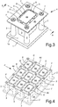
- the Fig. 1 accordingly shows a fastening arrangement for a component 3 to be fastened to a device 1, which component can be, for example, a solenoid control valve on a transmission actuator in an automated gearbox for commercial vehicles.
- the for the Fig. 1 selected section plane AA is in Fig. 3 recognizable.
- the component 3 to be fastened to a flat area 1a of the device 1 is arranged between four equally spaced, columnar spacers 2, the height of which is slightly smaller than the height of the component 3 to be fastened.
- the fastening element 4, 4 ' is designed as a sheet metal plate, in which openings 5, 5' surrounding the component 3 to be fastened, which form a weakened area of the fastening element 4, 4 ', are punched out or introduced in another suitable manner.
- These openings 5, 5 ' have a limited length and are defined by deformation zones designed as webs 6, 6' with a pressure and centering area 4a, 4a 'resting on a surface 3a of the component 3 to be fastened and a pressure and centering area 4a , 4a 'surrounding clamping frame 4b, 4b' connected.
- This clamping frame 4b, 4b ' forms an outer, non-weakened receiving area.
- the fastening element 4 designed as a sheet metal plate is initially flat before the clamping process and only rests with its pressure and centering area 4a on the surface 3a of the component 3 to be fastened, so that the outer, non-weakened receiving area designed as a sheet metal plate, designed as a clamping frame 4b Fastening element 4 has a defined distance from the upper end of the spacer 2. If the screws 7 are used as in Fig. 2 Tightened as shown, the outer, non-weakened receiving area designed as a tensioning frame 4b is pressed against the upper end of the spacer 2 by the screws 7, so that the deformation zone formed from the webs 6 is deformed. As a result, the pressure and centering area 4a is pressed against the surface 3a of the component 3 to be fastened with a force that is also dependent on the geometry of the webs 6.
- the fastening arrangement according to Fig. 4 is analogous to the mounting arrangement according to Fig. 3 constructed and comprises a device 1 'with sixteen equally spaced, columnar spacers 2 for nine components to be fastened 3.
- a fastening element 4' is provided, which has nine evenly distributed pressure and centering areas 4a '. These pressure and centering areas 4a 'are connected to a tensioning frame 4b' via a plurality of webs forming deformation zones 6 ', leaving open openings forming weakened areas 5'.
- the weakened area on a plate-shaped fastening element 8 consist of a circumferential groove 9, which is formed, for example, in its component-remote upper side.
- This groove 9 engages around the upper contact surface or surface 3a of the component 3 to be fastened and thereby delimits the pressure and centering area 8a of the fastening element 8.
- the remaining material of the fastening element 8 under the groove 9 forms a thin groove base 10, which represents a deformation zone.
- This groove base 10 has a suitably smaller thickness than the immediately adjacent area, the groove base 10 in this exemplary embodiment being about half as thick as the rest of the plate-shaped fastening element 8. The deformation of this deformation zone or the groove base 10 is after the screws 7 have been tightened in Fig. 6 shown.
- the plate-shaped fastening elements 4, 4 ′, 8 described can be designed as a sheet metal plate with punched openings 5, 5 ′ or with milled grooves 9. It is also possible, however, to design the fastening elements 4, 4 ', 8 as molded plastic parts into which the openings 5, 5' or the groove 9 are molded by appropriate design of the injection molds required for production.
Landscapes
- Engineering & Computer Science (AREA)
- General Engineering & Computer Science (AREA)
- Mechanical Engineering (AREA)
- Connection Of Plates (AREA)
- Clamps And Clips (AREA)
Description
- Die Erfindung betrifft eine Befestigungsanordnung für wenigstens eine Komponente an einem Gerät, aufweisend ein bereichsweise verformbares Befestigungselement, welches zur weitgehend spielfreien und formschlüssigen und/oder kraftschlüssigen Anbindung der wenigstens einen Komponente an das Gerät ausgebildet ist.
- Die Offenlegungsschrift
DE 31 20 117 A1 beschreibt ein Magnetsystem für ein Relais mit einem winkelförmigen Joch, dessen parallel zur Spulenachse angeordneter Jochschenkel beiderseits in Längsnuten eines Grundkörpers steckbar befestigt ist, wobei auf der der Spule zugewandten Seite des Jochschenkels ein Halteblech aus elastischem Metall angeordnet ist, das sich mit seinem Mittelteil am Jochschenkel abstützt und mit aufgebogenen Seitenteilen beiderseits in Längsnuten des Grundkörpers verspannt ist. Das Halteblech besitzt an beiden Seitenteilen in Einsteckrichtung des Jochschenkels aufgebogene Kufen, welche das Einstecken von Joch und Halteblech erleichtern sollen. Als zweckmäßig wird angesehen, wenn das Halteblech zumindest an einem Seitenteil eine entgegen der Einsteckrichtung des Joches aufgebogene, in eine Ausnehmung des Grundkörpers einrastbare Ecke aufweist. Hierdurch ist eine formschlüssige Halterung des Halteblechs entgegen der Einsteckrichtung des Jochs gegeben. - Die
DE 101 28 759 C1 offenbart ein Verfahren und eine Einrichtung zum gegenseitigen Festlegen von Spannblechen bei induktiven Bauelementen, beispielsweise zum Fixieren des Magnetkerns eines Transformators, eines Wandlers, einer Drossel, eines Filters oder eines sonstigen induktiven Bauelements über dafür vorgesehene Spannbleche, für das eine mechanische Fügetechnik, nämlich Clinchen oder Stanznieten, zur Anwendung kommt. Hierdurch wird eine unlösbare Festlegung der Spannbleche aneinander oder gegenüber sonstigen Tragkörpern erreicht. Diese Art der Festlegung geschieht ohne zusätzliche Spannelemente und ohne aufwendige konstruktive Ausgestaltung an den Spannblechen. - In der
DE 1 841 487 U1 ist eine Anordnung zur Befestigung eines als Fassung für die Kontaktfedern eines Relais dienenden Isolierkörpers an einem plattenförmigen Bauteil, beispielsweise einem Jochteil des magnetischen Kreises, des Relais, offenbart, bei der ein aus der auf dem plattenförmigen Bauteil aufliegenden Fläche des Isolierkörpers vorspringender und durch eine entsprechende Öffnung des plattenförmigen Bauteils mit geringem Spiel hindurchragender Steg mit rechteckigem Querschnitt nahe seinem freien Ende auf mindestens zwei gegenüberliegenden Flanken Nuten aufweist, in welche die Lappen einer sich auf dem plattenförmigen Bauteil abstützenden Spannfeder derart federnd eingreifen, dass dadurch die Auflagefläche des Isolierkörpers gegen das plattenförmigen Bauteil gepresst wird. - Die
US 5 730 210 A zeigt eine weitere vorbekannte Befestigungsanordnung. - Vor diesem Hintergrund liegt der Erfindung die Aufgabe zugrunde, eine kraftund formschlüssige Befestigungsanordnung vorzustellen, welche beispielsweise zur Befestigung von wenigstens einem Magnetregelventil an einem Getriebesteller eines automatisierten Schaltgetriebes nutzbar ist, und die einfach konstruiert ist sowie sich einfach montieren lässt.
- Gelöst wird diese Aufgabe mit einer Befestigungsanordnung für wenigstens eine Komponente an einem Gerät, aufweisend ein bereichsweise verformbares Befestigungselement, welches zur weitgehend spielfreien und formschlüssigen und/oder kraftschlüssigen Anbindung der wenigstens einen Komponente an das Gerät ausgebildet ist. Gemäß der Erfindung ist bei dieser Befestigungsanordnung vorgesehen, dass das Befestigungselement aus einer Platte besteht, dass das Befestigungselement zwischen wenigstens einem umlaufenden, ungeschwächten Aufnahmebereich und wenigstens einem auf einer Oberfläche der Komponente aufliegenden Druck- und Zentrierbereich Schwächungsbereiche und Deformationszonen aufweist, dass die wenigstens eine Komponente an einem Aufnahmebereich des Geräts angeordnet ist, dass sich von dem Aufnahmebereich des Geräts mehrere Abstandshalter bis unterhalb der Höhe der Oberfläche der wenigstens einen Komponente erstrecken, und dass der wenigstens eine ungeschwächte Aufnahmebereich des als Platte ausgebildeten Befestigungselements mittels Schrauben derart gegen die Abstandshalter verspannbar ist, dass sich die Deformationszonen verformen und der auf der Oberfläche der wenigstens einen Komponente aufliegende Druck- und Zentrierbereich die Komponente form- und/oder kraftschlüssig am Gerät fixiert.
- Die Befestigungsanordnung besteht somit aus wenigen Teilen, nämlich aus den Abstandshaltern zwischen dem Gerät und dem Befestigungselement sowie Schrauben zum Verspannen und Verformen des Befestigungselements auf einer Oberfläche der Komponente sowie gegen das Gerät. Durch die Verformung beim Verspannen des Befestigungselements, die der Oberfläche der Komponente angepasst ist, ergibt sich die sowohl kraftschlüssige als auch formschlüssige Befestigung der Komponente an dem Gerät.
- Um die kraftschlüssige und formschlüssige Befestigung der Komponente am Gerät zu erreichen ist bevorzugt vorgesehen, dass die erwähnten Schwächungsbereiche des als Platte ausgebildeten Befestigungselements als längliche Durchbrechungen ausgebildet sind, welche um den oder die Druck- und Zentrierbereiche herum angeordnet sind, und dass diese Schwächungsbereiche durch mehrere als Stege ausgebildete Deformationszonen voneinander beabstandet sind, welche zwischen den Druck- und Zentrierbereichen sowie einem als Spannrahmen ausgebildeten äußeren, ungeschwächten Aufnahmebereich angeordnet sind. Anstelle von länglichen Durchbrechungen in der Platte können auch runde Durchbrechungen, beispielsweise Bohrungen, vorgesehen sein, zwischen denen die erwähnten Stege angeordnet sind.
- Das als Platte ausgebildete Befestigungselement kann beispielsweise aus einer Blechplatte bestehen, in die als Durchbrechungen ausgeführte Schwächungsbereiche durch Ausstanzen eingebracht sind.
- Gemäß einer anderen Ausführungsform kann vorgesehen sein, dass der Schwächungsbereich des als Platte ausgebildeten Befestigungselements als eine zwischen den Druck- und Zentrierbereichen und dem Spannrahmen angeordnete umlaufende Nut ausgebildet ist, wobei deren Nutgrund die Deformationszone bildet, welcher eine geringere Dicke aufweist als der Druck- und Zentrierbereich sowie der Spannrahmen. Mit dem Begriff Nutgrund ist hier nicht die Oberfläche der tiefsten Stelle der Nut gemeint, sondern der unter der Nut verbliebene restliche Materialbereich des als Platte ausgebildeten Befestigungselements.
- Das als Platte ausgebildete Befestigungselement kann aus einer Blechplatte oder einer faserverstärkten Kunststoffplatte bestehen, in welche die als Schwächungsbereich ausgebildete Nut umlaufende Nut durch Fräsen oder Prägen oder durch Spritzgießformen des als Kunststoffplatte ausgebildeten Befestigungselements eingebracht sein.
- Die erwähnten Strukturen der Befestigungsanordnung lassen sich auf einfache Weise auch zur formschlüssigen und/oder kraftschlüssigen Befestigung von mehreren Komponenten an einem Gerät ausbilden. In diesem Fall weist die Befestigungsanordnung ein Befestigungselement in Form einer Platte mit mehreren Schwächungsbereichen in Form von Durchbrechungen oder in Form von Nuten und mit mehreren Deformationszonen in Form von Stegen oder Nutgründen auf. Diese Schwächungsbereiche und Deformationszonen sind zwischen mehreren Druck- und Zentrierbereichen sowie einen jeden der mehreren Druckund Zentrierbereiche, deren Schwächungsbereiche und Deformationszonen umgreifenden Spannrahmen angeordnet. Die Druck- und Zentrierbereiche sind hierbei gegen eine Mehrzahl von Abstandshaltern mittels Schrauben verspannbar.
- Die eingangs erwähnte Aufgabe wird des Weiteren durch einen Getriebesteller für ein automatisiertes Schaltgetriebe gelöst, welcher eine Befestigungsanordnung der vorstehend definierten Art aufweist.
- Ferner wird die vorstehend definierte Aufgabe auch durch die Verwendung einer Befestigungsanordnung der vorstehend definierten Art zur Befestigung eines Getriebestellers an einem automatisierten Schaltgetriebe für Nutzkraftwagen gelöst.
- Die Erfindung wird nachstehend anhand mehrerer in der Zeichnung dargestellter Ausführungsbeispiele näher erläutert. In der Zeichnung zeigt
-
Fig. 1 eine seitliche Schnittansicht einer Befestigungsanordnung gemäß der Erfindung in einer ersten Ausführungsform vor dem Verspannen eines Befestigungselements gegen eine Komponente an einem Gerät, -
Fig. 2 die seitliche Schnittansicht der Befestigungsanordnung gemäßFig. 1 nach dem Verspannen des Befestigungselements gegen die Komponente an einem Gerät, -
Fig. 3 eine perspektivische Darstellung der Ausführungsform gemäß denFiguren 1 und 2 nach dem Verspannen des Befestigungselements gegen eine Komponente, -
Fig. 4 eine perspektivische Darstellung einer zweiten Ausführungsform einer Befestigungsanordnung zur Befestigung von neun Komponenten an einem Gerät, -
Fig. 5 eine seitliche Schnittansicht einer Befestigungsanordnung gemäß der Erfindung in einer dritten Ausführungsform vor dem Verspannen des Befestigungselements gegen die Komponente an dem Gerät, und -
Fig. 6 eine seitliche Schnittansicht der Befestigungsanordnung gemäßFig. 5 nach dem Verspannen und Verformen des Befestigungselements gegen die Komponente an dem Gerät. - Die
Fig. 1 zeigt demnach eine Befestigungsanordnung für eine an einem Gerät 1 zu befestigende Komponente 3, welche beispielsweise ein Magnetregelventil an einem Getriebesteller in einem automatisierten Schaltgetriebe für Nutzkraftwagen sein kann. Die für dieFig. 1 gewählte Schnittebene A-A ist inFig. 3 erkennbar. Die an einem ebenen Bereich 1a des Geräts 1 zu befestigende Komponente 3 ist zwischen vier gleichmäßig beabstandeten, säulenförmigen Abstandshaltern 2 angeordnet, deren Höhe geringfügig kleiner als die Höhe der zu befestigenden Komponente 3 ist. - Beim Ausführungsbeispiel gemäß den
Figuren 1 bis 4 ist das Befestigungselement 4, 4' als Blechplatte ausgebildet, in die um die zu befestigende Komponente 3 umlaufende Durchbrechungen 5, 5', die einen Schwächungsbereich des als Blechplatte ausgebildeten Befestigungselements 4, 4' bilden, ausgestanzt oder auf andere geeignete Weise eingebracht sind. Diese Durchbrechungen 5, 5' weisen eine begrenzte Länge auf und sind durch als Stege 6, 6' ausgebildete Deformationszonen mit einem auf einer Oberfläche 3a der zu befestigenden Komponente 3 aufliegenden Druck- und Zentrierbereich 4a, 4a' und einem diesen Druck- und Zentrierbereich 4a, 4a' umgreifenden Spannrahmen 4b, 4b' verbunden. Dieser Spannrahmen 4b, 4b' bildet einen äußeren, ungeschwächten Aufnahmebereich. - Wie
Fig. 1 zeigt, ist das als Blechplatte ausgebildete Befestigungselement 4 vor dem Verspannvorgang zunächst eben und liegt nur mit seinem Druck- und Zentrierbereich 4a auf der Oberfläche 3a der zu befestigenden Komponente 3 auf, so dass der als Spannrahmen 4b ausgebildete äußere, ungeschwächte Aufnahmebereich des als Blechplatte ausgebildeten Befestigungselements 4 einen definierten Abstand zum oberen Ende der Abstandshalter 2 aufweist. Werden die Schrauben 7 wie inFig. 2 dargestellt angezogen, so wird der als Spannrahmen 4b ausgebildete äußere, ungeschwächte Aufnahmebereich gegen das oberen Ende der Abstandshalter 2 durch die Schrauben 7 gepresst, so dass sich die aus den Stegen 6 gebildete Deformationszone verformt. Im Ergebnis wird dabei der Druck- und Zentrierbereich 4a mit einer auch von der Geometrie der Stege 6 abhängigen Kraft gegen die Oberfläche 3a der zu befestigenden Komponente 3 gepresst. - Aus
Fig. 2 ist ersichtlich, dass sich durch die Verformung der aus den Stegen 6 gebildeten Deformationszone 6, zusätzlich zu der kraftschlüssigen Verbindung über den Druck- und Zentrierbereich 4a, eine formschlüssige Fixierung der zu befestigenden Komponente 3 ergibt, so dass eine formschlüssige und kraftschlüssige Verbindung der zu befestigenden Komponente 3 am Gerät 1 resultiert, ohne die zu befestigende Komponente 3 mechanisch zu überbeanspruchen. - Die Befestigungsanordnung gemäß
Fig. 4 ist analog zu der Befestigungsanordnung gemäßFig. 3 aufgebaut und umfasst ein Gerät 1' mit sechzehn gleichmäßig zueinander beabstandeten, säulenförmigen Abstandshaltern 2 für neun zu befestigende Komponenten 3. Hierzu ist ein Befestigungselement 4' vorgesehen, das neun gleichmäßig verteilt angeordnete Druck- und Zentrierbereiche 4a' aufweist. Diese Druck- und Zentrierbereiche 4a' sind über eine Mehrzahl von Deformationszonen 6' bildenden Stegen mit einem Spannrahmen 4b' unter Freilassung von Schwächungsbereiche 5' bildenden Durchbrechungen verbunden. Beim Verspannen dieses Spannrahmens 4b' für eine Mehrzahl von zu befestigenden Komponenten 3 wird durch Anziehen der Schrauben 7 in den Abstandshaltern 2 der Spannrahmens 4b' gegen die Komponenten 3 verspannt und ergibt die sowohl ausFig. 4 als auch ausFig. 2 ersichtliche Verformung der Druck- und Zentrierbereiche 4a' gegenüber dem Spannrahmen 4b' für die zu befestigenden Komponenten 3 mit den bereits genannten Vorteilen. - Anstatt der in den
Figuren 1 bis 4 gezeigten ausgestanzten Durchbrechungen 5, 5' kann gemäß dem in denFiguren 5 und 6 dargestellten Ausführungsbeispiel der Schwächungsbereich an einem plattenförmigen Befestigungselement 8 aus einer umlaufenden Nut 9 bestehen, welche beispielsweise in dessen komponentenfernen Oberseite ausgebildet ist. Diese Nut 9 umgreift die obere Anlagefläche beziehungsweise Oberfläche 3a der zu befestigenden Komponente 3 und begrenzt dadurch den Druck- und Zentrierbereich 8a des Befestigungselements 8. WieFig. 5 zeigt, bildet der unter der Nut 9 verbliebene Materialrest des Befestigungselements 8 einen dünnen Nutgrund 10, welcher eine Deformationszone darstellt. Dieser Nutgrund 10 weist eine geeignete geringere Dicke auf als der unmittelbar benachbarte Bereich, wobei der Nutgrund 10 in diesem Ausführungsbeispiel etwa halb so dick ist wie der Rest des plattenförmigen Befestigungselements 8. Die Verformung dieser Deformationszone beziehungsweise des Nutgrunds 10 nach dem Anziehen der Schrauben 7 ist inFig. 6 dargestellt. - Die beschriebenen plattenförmigen Befestigungselemente 4, 4', 8 können als Blechplatte mit eingestanzten Durchbrechungen 5, 5' oder mit eingefrästen Nuten 9 ausgeführt sein. Es ist aber auch möglich, die Befestigungselemente 4, 4', 8 als Kunststoffformteile auszubilden, in welche die Durchbrechungen 5, 5' oder die Nut 9 durch entsprechende Ausbildung der für die Herstellung benötigten Spritzgussformen eingeformt sind.
Claims (8)
- Befestigungsanordnung für wenigstens eine Komponente (3) an einem Gerät (1, 1'), wobei die wenigstens eine Komponente (3) an einem Aufnahmebereich (1a) des Geräts (1) angeordnet ist,wobei die Befestigungsanordnung ein bereichsweise verformbares Befestigungselement (4, 4', 8) aufweist, welches zur weitgehend spielfreien und formschlüssigen und/oder kraftschlüssigen Anbindung der wenigstens einen Komponente (3) an das Gerät (1, 1') ausgebildet ist,dadurch gekennzeichnet,- dass das Befestigungselement (4, 4', 8) aus einer Platte besteht,- dass das Befestigungselement (4, 4', 8) zwischen wenigstens einem umlaufenden, ungeschwächten Aufnahmebereich (4b, 4b', 8b) und wenigstens einem auf einer Oberfläche (3a) der Komponente (3) auflegbaren Druck- und Zentrierbereich (4a, 4a', 8a) Schwächungsbereiche (5, 5', 9) und Deformationszonen (6, 6', 10) aufweist,- dass die Befestigungsanordnung mehrere Abstandshalter (2) aufweist und die mehreren Abstandshalter (2) sich von dem Aufnahmebereich (1a) des Geräts (1) bis unterhalb der Höhe der Oberfläche (3a) der wenigstens einen Komponente (3) erstrecken können, und- dass die Befestigungsanordnung Schrauben (7) aufweist und der wenigstens eine ungeschwächte Aufnahmebereich (4b, 4b', 8b) des als Platte ausgebildeten Befestigungselements (4, 4', 8b) mittels der Schrauben (7) derart gegen die Abstandshalter (2) verspannbar ist, dass sich die Deformationszonen (6, 6', 10) verformen und der auf der Oberfläche (3a) der wenigstens einen Komponente (3) auflegbare Druck- und Zentrierbereich (4a, 4a', 8a) die Komponente (3) form- und/oder kraftschlüssig am Gerät (1) fixiert.
- Befestigungsanordnung nach Anspruch 1, dadurch gekennzeichnet, dass die Schwächungsbereiche (5, 5') des als Platte ausgebildeten Befestigungselements (4, 4') als längliche Durchbrechungen ausgebildet sind, welche um den oder die Druck- und Zentrierbereiche (4a, 4a') herum angeordnet sind, und dass die Schwächungsbereiche (5, 5') durch mehrere als Stege ausgebildete Deformationszonen (6, 6') voneinander beabstandet sind, welche zwischen den Druck- und Zentrierbereichen (4a, 4a') sowie einem als Spannrahmen ausgebildeten äußeren, ungeschwächten Aufnahmebereich (4b, 4b') angeordnet sind.
- Befestigungsanordnung nach Anspruch 2, dadurch gekennzeichnet, dass das Befestigungselement (4, 4') aus einer Blechplatte besteht, in die als Durchbrechungen ausgeführten Schwächungsbereiche (5, 5') durch Ausstanzen erzeugt sind.
- Befestigungsanordnung nach einem der Ansprüche 2 und 3, dadurch gekennzeichnet, dass der Schwächungsbereich (9) des als Platte ausgebildeten Befestigungselements (8) als eine zwischen den Druck- und Zentrierbereichen (8a) und dem Spannrahmen (8b) angeordnete umlaufende Nut ausgebildet ist, wobei deren Nutgrund (10) die Deformationszone bildet, welcher eine geringere Dicke aufweist als der Druck- und Zentrierbereich (8a) sowie der Spannrahmen (8b).
- Befestigungsanordnung nach Anspruch 4, dadurch gekennzeichnet, dass das als Platte ausgebildete Befestigungselement (8) aus einer Blechplatte oder einer faserverstärkten Kunststoffplatte besteht, in welche die als Schwächungsbereich (9) ausgebildete umlaufende Nut durch Fräsen oder Prägen oder durch Spritzgussformen des als Kunststoffplatte ausgebildeten Befestigungselements (8) eingebracht ist.
- Befestigungsanordnung nach einem der Ansprüche 2 bis 5, dadurch gekennzeichnet,dass diese zur form- und/oder kraftschlüssigen Befestigung von mehreren Komponenten (3) an einem Gerät (1') ausgebildet ist, aufweisend ein Befestigungselement (4') in Form einer Platte mit mehreren Schwächungsbereichen (5'; 9) in Form von Durchbrechungen oder in Form von Nuten und mit mehreren Deformationszonen (6', 10) in Form von Stegen oder Nutgründen zwischen mehreren Druck- und Zentrierbereich en (4a', 8a) sowie aufweisend einen jeden der mehreren Druck- und Zentrierbereiche (4a', 8a),deren Schwächungsbereiche (5'; 9) und Deformationszonen (6'; 10) umgreifenden Spannrahmen (4a', 8), wobei die Druck- und Zentrierbereiche (4a', 8a) gegen die Mehrzahl von Abstandshaltern (2) mittels der Schrauben (7) verspannbar ist.
- Getriebesteller (1) in einem automatisierten Getriebe für Nutzkraftwagen mit einer Befestigungsanordnung mit den Merkmalen von einem oder mehreren der Ansprüche 1 bis 6.
- Verwendung einer Befestigungsanordnung nach einem oder mehreren der Ansprüche 1 bis 6 zur Befestigung eines Getriebestellers (1) an einem automatisierten Schaltgetriebe für Nutzkraftwagen.
Applications Claiming Priority (2)
| Application Number | Priority Date | Filing Date | Title |
|---|---|---|---|
| DE102017002357.3A DE102017002357A1 (de) | 2017-03-10 | 2017-03-10 | Befestigungsanordnung zur Befestigung wenigstens einer Komponente an einem Gerät |
| PCT/EP2018/054208 WO2018162230A1 (de) | 2017-03-10 | 2018-02-21 | Befestigungsanordnung zur befestigung wenigstens einer komponente an einem gerät |
Publications (2)
| Publication Number | Publication Date |
|---|---|
| EP3592992A1 EP3592992A1 (de) | 2020-01-15 |
| EP3592992B1 true EP3592992B1 (de) | 2021-09-01 |
Family
ID=61274250
Family Applications (1)
| Application Number | Title | Priority Date | Filing Date |
|---|---|---|---|
| EP18707004.0A Active EP3592992B1 (de) | 2017-03-10 | 2018-02-21 | Befestigungsanordnung zur befestigung wenigstens einer komponente an einem gerät |
Country Status (6)
| Country | Link |
|---|---|
| US (1) | US11300146B2 (de) |
| EP (1) | EP3592992B1 (de) |
| CN (1) | CN110226046B (de) |
| BR (1) | BR112019018716B1 (de) |
| DE (1) | DE102017002357A1 (de) |
| WO (1) | WO2018162230A1 (de) |
Families Citing this family (1)
| Publication number | Priority date | Publication date | Assignee | Title |
|---|---|---|---|---|
| DE102019126129A1 (de) | 2019-09-27 | 2021-04-01 | Wabco Europe Bvba | Steuerungsmodul eines Fahrzeugs |
Family Cites Families (26)
| Publication number | Priority date | Publication date | Assignee | Title |
|---|---|---|---|---|
| DE1841487U (de) | 1961-07-19 | 1961-11-16 | Landis & Gyr Ag | Anordnung zur befestigung der kontaktfederfassungen von relais. |
| DE3120117C2 (de) | 1981-05-20 | 1984-10-31 | Siemens AG, 1000 Berlin und 8000 München | Magnetsystem für ein Relais |
| US5504652A (en) * | 1994-09-16 | 1996-04-02 | Apple Computer, Inc. | Unitary heat sink for integrated circuits |
| US5730210A (en) * | 1997-02-24 | 1998-03-24 | Silicon Integrated Systems Corporation | Heat sink having an assembling device |
| TW585387U (en) * | 2000-04-20 | 2004-04-21 | Foxconn Prec Components Co Ltd | Heat sink locking device |
| DE10128759C1 (de) | 2001-06-07 | 2003-04-24 | Siemens Ag | Verfahren und Einrichtung zum gegenseitigen Festlegen von Spannblechen bei induktiven Bauelementen |
| US7232332B2 (en) * | 2003-01-07 | 2007-06-19 | Sun Microsystems, Inc. | Support and grounding structure |
| JP2005009582A (ja) * | 2003-06-19 | 2005-01-13 | Sumitomo Electric Ind Ltd | 低温用の締結構造 |
| US6950310B2 (en) * | 2003-12-31 | 2005-09-27 | Texas Instruments Incorporated | System and method for self-leveling heat sink for multiple height devices |
| US7344345B2 (en) * | 2004-05-27 | 2008-03-18 | Southco, Inc. | Captive shoulder nut having spring tie-down |
| CN2713636Y (zh) * | 2004-06-11 | 2005-07-27 | 鸿富锦精密工业(深圳)有限公司 | 散热器扣合装置 |
| TW200602845A (en) * | 2004-07-09 | 2006-01-16 | Delta Electronics Inc | Heat dispersion apparatus |
| CN100377341C (zh) * | 2004-08-13 | 2008-03-26 | 鸿富锦精密工业(深圳)有限公司 | 散热装置及其制造方法 |
| TWM296401U (en) * | 2006-03-07 | 2006-08-21 | Cooler Master Co Ltd | Fixed structure of heat sink |
| US7375963B2 (en) * | 2006-04-11 | 2008-05-20 | International Business Machines Corporation | System and method for cooling a module |
| US8053888B2 (en) * | 2006-12-01 | 2011-11-08 | Harman International Industries, Incorporated | System for clamping heat sink |
| JP2008203376A (ja) * | 2007-02-19 | 2008-09-04 | Matsushita Electric Ind Co Ltd | 半導体装置、並びに表示装置 |
| TWI324292B (en) * | 2007-03-09 | 2010-05-01 | Ama Precision Inc | Fixing method and device thereof |
| CN101662919B (zh) * | 2008-08-27 | 2012-07-25 | 富准精密工业(深圳)有限公司 | 散热装置 |
| US9379037B2 (en) * | 2014-03-14 | 2016-06-28 | Apple Inc. | Thermal module accounting for increased board/die size in a portable computer |
| TWI566345B (zh) * | 2014-09-05 | 2017-01-11 | 台達電子工業股份有限公司 | 用於夾持電子元件的夾具 |
| US9414481B1 (en) * | 2015-04-02 | 2016-08-09 | Cooler Master Technology Inc. | Heat sink fastener |
| JP2016213314A (ja) * | 2015-05-08 | 2016-12-15 | 富士通株式会社 | 冷却モジュール及び電子機器 |
| JP2017050493A (ja) * | 2015-09-04 | 2017-03-09 | 株式会社東芝 | 電子機器 |
| US10103084B2 (en) * | 2015-10-20 | 2018-10-16 | LWE, Inc. | System and method for clamping press pack high power semiconductor |
| DE202016006601U1 (de) * | 2016-10-25 | 2017-01-25 | Michael Weber | Vorrichtung für eine individuelle geometrische Ausrichtung eines Befestigungselementes an Wand- oder Deckenelementen |
-
2017
- 2017-03-10 DE DE102017002357.3A patent/DE102017002357A1/de not_active Withdrawn
-
2018
- 2018-02-21 WO PCT/EP2018/054208 patent/WO2018162230A1/de not_active Ceased
- 2018-02-21 CN CN201880008555.7A patent/CN110226046B/zh active Active
- 2018-02-21 EP EP18707004.0A patent/EP3592992B1/de active Active
- 2018-02-21 BR BR112019018716-2A patent/BR112019018716B1/pt not_active IP Right Cessation
- 2018-02-21 US US16/492,791 patent/US11300146B2/en active Active
Also Published As
| Publication number | Publication date |
|---|---|
| CN110226046A (zh) | 2019-09-10 |
| BR112019018716A2 (pt) | 2020-04-07 |
| WO2018162230A1 (de) | 2018-09-13 |
| US20200056642A1 (en) | 2020-02-20 |
| DE102017002357A1 (de) | 2018-09-13 |
| US20200400172A9 (en) | 2020-12-24 |
| US11300146B2 (en) | 2022-04-12 |
| EP3592992A1 (de) | 2020-01-15 |
| BR112019018716B1 (pt) | 2023-09-26 |
| CN110226046B (zh) | 2021-06-08 |
Similar Documents
| Publication | Publication Date | Title |
|---|---|---|
| EP1770337B1 (de) | Noppenplatte mit Zwischennoppen | |
| WO2000008353A1 (de) | Piezoelektrische aktoreinheit | |
| DE102010060742A1 (de) | Form zur Herstellung von Betonformsteinen | |
| EP1941169A1 (de) | Vorrichtung zum verbinden mit einer schraube | |
| WO2017016844A1 (de) | Befestigungsanordnung, clipkörper und clip | |
| EP3529868B1 (de) | Verbindungsanordnung für die verbindung von zwei schaltschrankrahmengestellen | |
| EP0458254A2 (de) | Befestigungsvorrichtung zur Befestigung eines Griffelementes an einem Kochgeschirr | |
| EP3592992A1 (de) | Befestigungsanordnung zur befestigung wenigstens einer komponente an einem gerät | |
| WO2015117798A1 (de) | Verfahren zum fixieren von bauteilen | |
| DE7402795U (de) | Elektromagnetisches Schütz | |
| DE3602633C2 (de) | ||
| EP2066930A1 (de) | Dichtungsanordnung | |
| EP0126794A1 (de) | Vorrichtung zur elektromechanischen Steuerung und/oder Sicherung von Maschinenbewegungen | |
| EP0177798B1 (de) | An einer Platine lösbar befestigbarer Elektromagnet | |
| DE2536740B2 (de) | Kontaktfedersatz für elektromagnetische Relais | |
| DE3420423C2 (de) | ||
| DE3526195A1 (de) | Induktives bauelement | |
| WO2007009511A1 (de) | Kontaktfeder in einem trägerrahmen eines antennenverstärkers eines fahrzeuges | |
| DE4318828C2 (de) | Einbaugerät, insbesondere Einbauspüle | |
| DE2433806A1 (de) | Loesbare verbindung mindestens zweier blechprofiltraeger miteinander | |
| DE102007026415A1 (de) | Ringförmiges, axiales Sicherungselement | |
| DE2926081C2 (de) | ||
| CH692833A5 (de) | Einrichtung zum Zusammenfügen zweier Teile eines Gehäuses. | |
| DE3445514A1 (de) | Korb-blindmutter | |
| DE102023132949A1 (de) | Haushaltgerätekomponente und Verfahren zum Verbinder zweier Bauteile |
Legal Events
| Date | Code | Title | Description |
|---|---|---|---|
| STAA | Information on the status of an ep patent application or granted ep patent |
Free format text: STATUS: UNKNOWN |
|
| STAA | Information on the status of an ep patent application or granted ep patent |
Free format text: STATUS: THE INTERNATIONAL PUBLICATION HAS BEEN MADE |
|
| PUAI | Public reference made under article 153(3) epc to a published international application that has entered the european phase |
Free format text: ORIGINAL CODE: 0009012 |
|
| STAA | Information on the status of an ep patent application or granted ep patent |
Free format text: STATUS: REQUEST FOR EXAMINATION WAS MADE |
|
| 17P | Request for examination filed |
Effective date: 20191010 |
|
| AK | Designated contracting states |
Kind code of ref document: A1 Designated state(s): AL AT BE BG CH CY CZ DE DK EE ES FI FR GB GR HR HU IE IS IT LI LT LU LV MC MK MT NL NO PL PT RO RS SE SI SK SM TR |
|
| AX | Request for extension of the european patent |
Extension state: BA ME |
|
| DAV | Request for validation of the european patent (deleted) | ||
| DAX | Request for extension of the european patent (deleted) | ||
| STAA | Information on the status of an ep patent application or granted ep patent |
Free format text: STATUS: EXAMINATION IS IN PROGRESS |
|
| 17Q | First examination report despatched |
Effective date: 20201127 |
|
| RAP3 | Party data changed (applicant data changed or rights of an application transferred) |
Owner name: ZF CV SYSTEMS HANNOVER GMBH |
|
| GRAP | Despatch of communication of intention to grant a patent |
Free format text: ORIGINAL CODE: EPIDOSNIGR1 |
|
| STAA | Information on the status of an ep patent application or granted ep patent |
Free format text: STATUS: GRANT OF PATENT IS INTENDED |
|
| GRAS | Grant fee paid |
Free format text: ORIGINAL CODE: EPIDOSNIGR3 |
|
| INTG | Intention to grant announced |
Effective date: 20210629 |
|
| GRAA | (expected) grant |
Free format text: ORIGINAL CODE: 0009210 |
|
| STAA | Information on the status of an ep patent application or granted ep patent |
Free format text: STATUS: THE PATENT HAS BEEN GRANTED |
|
| AK | Designated contracting states |
Kind code of ref document: B1 Designated state(s): AL AT BE BG CH CY CZ DE DK EE ES FI FR GB GR HR HU IE IS IT LI LT LU LV MC MK MT NL NO PL PT RO RS SE SI SK SM TR |
|
| REG | Reference to a national code |
Ref country code: GB Ref legal event code: FG4D Free format text: NOT ENGLISH |
|
| REG | Reference to a national code |
Ref country code: CH Ref legal event code: EP Ref country code: AT Ref legal event code: REF Ref document number: 1426531 Country of ref document: AT Kind code of ref document: T Effective date: 20210915 |
|
| REG | Reference to a national code |
Ref country code: DE Ref legal event code: R096 Ref document number: 502018006828 Country of ref document: DE |
|
| REG | Reference to a national code |
Ref country code: IE Ref legal event code: FG4D Free format text: LANGUAGE OF EP DOCUMENT: GERMAN |
|
| REG | Reference to a national code |
Ref country code: LT Ref legal event code: MG9D |
|
| REG | Reference to a national code |
Ref country code: NL Ref legal event code: MP Effective date: 20210901 |
|
| PG25 | Lapsed in a contracting state [announced via postgrant information from national office to epo] |
Ref country code: BG Free format text: LAPSE BECAUSE OF FAILURE TO SUBMIT A TRANSLATION OF THE DESCRIPTION OR TO PAY THE FEE WITHIN THE PRESCRIBED TIME-LIMIT Effective date: 20211201 Ref country code: LT Free format text: LAPSE BECAUSE OF FAILURE TO SUBMIT A TRANSLATION OF THE DESCRIPTION OR TO PAY THE FEE WITHIN THE PRESCRIBED TIME-LIMIT Effective date: 20210901 Ref country code: NO Free format text: LAPSE BECAUSE OF FAILURE TO SUBMIT A TRANSLATION OF THE DESCRIPTION OR TO PAY THE FEE WITHIN THE PRESCRIBED TIME-LIMIT Effective date: 20211201 Ref country code: ES Free format text: LAPSE BECAUSE OF FAILURE TO SUBMIT A TRANSLATION OF THE DESCRIPTION OR TO PAY THE FEE WITHIN THE PRESCRIBED TIME-LIMIT Effective date: 20210901 Ref country code: FI Free format text: LAPSE BECAUSE OF FAILURE TO SUBMIT A TRANSLATION OF THE DESCRIPTION OR TO PAY THE FEE WITHIN THE PRESCRIBED TIME-LIMIT Effective date: 20210901 Ref country code: HR Free format text: LAPSE BECAUSE OF FAILURE TO SUBMIT A TRANSLATION OF THE DESCRIPTION OR TO PAY THE FEE WITHIN THE PRESCRIBED TIME-LIMIT Effective date: 20210901 Ref country code: RS Free format text: LAPSE BECAUSE OF FAILURE TO SUBMIT A TRANSLATION OF THE DESCRIPTION OR TO PAY THE FEE WITHIN THE PRESCRIBED TIME-LIMIT Effective date: 20210901 Ref country code: SE Free format text: LAPSE BECAUSE OF FAILURE TO SUBMIT A TRANSLATION OF THE DESCRIPTION OR TO PAY THE FEE WITHIN THE PRESCRIBED TIME-LIMIT Effective date: 20210901 |
|
| PG25 | Lapsed in a contracting state [announced via postgrant information from national office to epo] |
Ref country code: PL Free format text: LAPSE BECAUSE OF FAILURE TO SUBMIT A TRANSLATION OF THE DESCRIPTION OR TO PAY THE FEE WITHIN THE PRESCRIBED TIME-LIMIT Effective date: 20210901 Ref country code: LV Free format text: LAPSE BECAUSE OF FAILURE TO SUBMIT A TRANSLATION OF THE DESCRIPTION OR TO PAY THE FEE WITHIN THE PRESCRIBED TIME-LIMIT Effective date: 20210901 Ref country code: GR Free format text: LAPSE BECAUSE OF FAILURE TO SUBMIT A TRANSLATION OF THE DESCRIPTION OR TO PAY THE FEE WITHIN THE PRESCRIBED TIME-LIMIT Effective date: 20211202 |
|
| REG | Reference to a national code |
Ref country code: DE Ref legal event code: R081 Ref document number: 502018006828 Country of ref document: DE Owner name: ZF CV SYSTEMS EUROPE BV, BE Free format text: FORMER OWNER: ZF CV SYSTEMS HANNOVER GMBH, 30453 HANNOVER, DE |
|
| PG25 | Lapsed in a contracting state [announced via postgrant information from national office to epo] |
Ref country code: IS Free format text: LAPSE BECAUSE OF FAILURE TO SUBMIT A TRANSLATION OF THE DESCRIPTION OR TO PAY THE FEE WITHIN THE PRESCRIBED TIME-LIMIT Effective date: 20220101 Ref country code: SM Free format text: LAPSE BECAUSE OF FAILURE TO SUBMIT A TRANSLATION OF THE DESCRIPTION OR TO PAY THE FEE WITHIN THE PRESCRIBED TIME-LIMIT Effective date: 20210901 Ref country code: SK Free format text: LAPSE BECAUSE OF FAILURE TO SUBMIT A TRANSLATION OF THE DESCRIPTION OR TO PAY THE FEE WITHIN THE PRESCRIBED TIME-LIMIT Effective date: 20210901 Ref country code: RO Free format text: LAPSE BECAUSE OF FAILURE TO SUBMIT A TRANSLATION OF THE DESCRIPTION OR TO PAY THE FEE WITHIN THE PRESCRIBED TIME-LIMIT Effective date: 20210901 Ref country code: PT Free format text: LAPSE BECAUSE OF FAILURE TO SUBMIT A TRANSLATION OF THE DESCRIPTION OR TO PAY THE FEE WITHIN THE PRESCRIBED TIME-LIMIT Effective date: 20220103 Ref country code: NL Free format text: LAPSE BECAUSE OF FAILURE TO SUBMIT A TRANSLATION OF THE DESCRIPTION OR TO PAY THE FEE WITHIN THE PRESCRIBED TIME-LIMIT Effective date: 20210901 Ref country code: EE Free format text: LAPSE BECAUSE OF FAILURE TO SUBMIT A TRANSLATION OF THE DESCRIPTION OR TO PAY THE FEE WITHIN THE PRESCRIBED TIME-LIMIT Effective date: 20210901 Ref country code: CZ Free format text: LAPSE BECAUSE OF FAILURE TO SUBMIT A TRANSLATION OF THE DESCRIPTION OR TO PAY THE FEE WITHIN THE PRESCRIBED TIME-LIMIT Effective date: 20210901 Ref country code: AL Free format text: LAPSE BECAUSE OF FAILURE TO SUBMIT A TRANSLATION OF THE DESCRIPTION OR TO PAY THE FEE WITHIN THE PRESCRIBED TIME-LIMIT Effective date: 20210901 |
|
| REG | Reference to a national code |
Ref country code: DE Ref legal event code: R097 Ref document number: 502018006828 Country of ref document: DE |
|
| PLBE | No opposition filed within time limit |
Free format text: ORIGINAL CODE: 0009261 |
|
| STAA | Information on the status of an ep patent application or granted ep patent |
Free format text: STATUS: NO OPPOSITION FILED WITHIN TIME LIMIT |
|
| PG25 | Lapsed in a contracting state [announced via postgrant information from national office to epo] |
Ref country code: IT Free format text: LAPSE BECAUSE OF FAILURE TO SUBMIT A TRANSLATION OF THE DESCRIPTION OR TO PAY THE FEE WITHIN THE PRESCRIBED TIME-LIMIT Effective date: 20210901 Ref country code: DK Free format text: LAPSE BECAUSE OF FAILURE TO SUBMIT A TRANSLATION OF THE DESCRIPTION OR TO PAY THE FEE WITHIN THE PRESCRIBED TIME-LIMIT Effective date: 20210901 |
|
| 26N | No opposition filed |
Effective date: 20220602 |
|
| PG25 | Lapsed in a contracting state [announced via postgrant information from national office to epo] |
Ref country code: SI Free format text: LAPSE BECAUSE OF FAILURE TO SUBMIT A TRANSLATION OF THE DESCRIPTION OR TO PAY THE FEE WITHIN THE PRESCRIBED TIME-LIMIT Effective date: 20210901 |
|
| PG25 | Lapsed in a contracting state [announced via postgrant information from national office to epo] |
Ref country code: MC Free format text: LAPSE BECAUSE OF FAILURE TO SUBMIT A TRANSLATION OF THE DESCRIPTION OR TO PAY THE FEE WITHIN THE PRESCRIBED TIME-LIMIT Effective date: 20210901 |
|
| REG | Reference to a national code |
Ref country code: CH Ref legal event code: PL |
|
| REG | Reference to a national code |
Ref country code: BE Ref legal event code: MM Effective date: 20220228 |
|
| PG25 | Lapsed in a contracting state [announced via postgrant information from national office to epo] |
Ref country code: LU Free format text: LAPSE BECAUSE OF NON-PAYMENT OF DUE FEES Effective date: 20220221 |
|
| PG25 | Lapsed in a contracting state [announced via postgrant information from national office to epo] |
Ref country code: LI Free format text: LAPSE BECAUSE OF NON-PAYMENT OF DUE FEES Effective date: 20220228 Ref country code: IE Free format text: LAPSE BECAUSE OF NON-PAYMENT OF DUE FEES Effective date: 20220221 Ref country code: CH Free format text: LAPSE BECAUSE OF NON-PAYMENT OF DUE FEES Effective date: 20220228 |
|
| PG25 | Lapsed in a contracting state [announced via postgrant information from national office to epo] |
Ref country code: BE Free format text: LAPSE BECAUSE OF NON-PAYMENT OF DUE FEES Effective date: 20220228 |
|
| P01 | Opt-out of the competence of the unified patent court (upc) registered |
Effective date: 20230528 |
|
| REG | Reference to a national code |
Ref country code: AT Ref legal event code: MM01 Ref document number: 1426531 Country of ref document: AT Kind code of ref document: T Effective date: 20230221 |
|
| PG25 | Lapsed in a contracting state [announced via postgrant information from national office to epo] |
Ref country code: AT Free format text: LAPSE BECAUSE OF NON-PAYMENT OF DUE FEES Effective date: 20230221 |
|
| PG25 | Lapsed in a contracting state [announced via postgrant information from national office to epo] |
Ref country code: MK Free format text: LAPSE BECAUSE OF FAILURE TO SUBMIT A TRANSLATION OF THE DESCRIPTION OR TO PAY THE FEE WITHIN THE PRESCRIBED TIME-LIMIT Effective date: 20210901 Ref country code: CY Free format text: LAPSE BECAUSE OF FAILURE TO SUBMIT A TRANSLATION OF THE DESCRIPTION OR TO PAY THE FEE WITHIN THE PRESCRIBED TIME-LIMIT Effective date: 20210901 Ref country code: AT Free format text: LAPSE BECAUSE OF NON-PAYMENT OF DUE FEES Effective date: 20230221 |
|
| PGFP | Annual fee paid to national office [announced via postgrant information from national office to epo] |
Ref country code: GB Payment date: 20240108 Year of fee payment: 7 |
|
| PG25 | Lapsed in a contracting state [announced via postgrant information from national office to epo] |
Ref country code: HU Free format text: LAPSE BECAUSE OF FAILURE TO SUBMIT A TRANSLATION OF THE DESCRIPTION OR TO PAY THE FEE WITHIN THE PRESCRIBED TIME-LIMIT; INVALID AB INITIO Effective date: 20180221 |
|
| PGFP | Annual fee paid to national office [announced via postgrant information from national office to epo] |
Ref country code: FR Payment date: 20240103 Year of fee payment: 7 |
|
| PG25 | Lapsed in a contracting state [announced via postgrant information from national office to epo] |
Ref country code: MT Free format text: LAPSE BECAUSE OF FAILURE TO SUBMIT A TRANSLATION OF THE DESCRIPTION OR TO PAY THE FEE WITHIN THE PRESCRIBED TIME-LIMIT Effective date: 20210901 |
|
| GBPC | Gb: european patent ceased through non-payment of renewal fee |
Effective date: 20250221 |
|
| PG25 | Lapsed in a contracting state [announced via postgrant information from national office to epo] |
Ref country code: TR Free format text: LAPSE BECAUSE OF FAILURE TO SUBMIT A TRANSLATION OF THE DESCRIPTION OR TO PAY THE FEE WITHIN THE PRESCRIBED TIME-LIMIT Effective date: 20210901 |
|
| PG25 | Lapsed in a contracting state [announced via postgrant information from national office to epo] |
Ref country code: GB Free format text: LAPSE BECAUSE OF NON-PAYMENT OF DUE FEES Effective date: 20250221 |
|
| PG25 | Lapsed in a contracting state [announced via postgrant information from national office to epo] |
Ref country code: FR Free format text: LAPSE BECAUSE OF NON-PAYMENT OF DUE FEES Effective date: 20250228 |
|
| PGFP | Annual fee paid to national office [announced via postgrant information from national office to epo] |
Ref country code: DE Payment date: 20251230 Year of fee payment: 9 |
|
| PGFP | Annual fee paid to national office [announced via postgrant information from national office to epo] |
Ref country code: AT Payment date: 20260410 Year of fee payment: 5 |