EP3591918B1 - Method and system for implementing data transmission using ground balise - Google Patents
Method and system for implementing data transmission using ground balise Download PDFInfo
- Publication number
- EP3591918B1 EP3591918B1 EP18868646.3A EP18868646A EP3591918B1 EP 3591918 B1 EP3591918 B1 EP 3591918B1 EP 18868646 A EP18868646 A EP 18868646A EP 3591918 B1 EP3591918 B1 EP 3591918B1
- Authority
- EP
- European Patent Office
- Prior art keywords
- control data
- unit
- vehicle running
- running control
- balise
- Prior art date
- Legal status (The legal status is an assumption and is not a legal conclusion. Google has not performed a legal analysis and makes no representation as to the accuracy of the status listed.)
- Active
Links
- 238000000034 method Methods 0.000 title claims description 44
- 230000005540 biological transmission Effects 0.000 title claims description 12
- 239000003990 capacitor Substances 0.000 claims description 80
- 238000013500 data storage Methods 0.000 claims description 39
- 239000011324 bead Substances 0.000 claims description 23
- 238000004891 communication Methods 0.000 claims description 8
- 238000006243 chemical reaction Methods 0.000 claims description 3
- 238000010586 diagram Methods 0.000 description 10
- 238000005516 engineering process Methods 0.000 description 2
- 238000010276 construction Methods 0.000 description 1
- 239000013078 crystal Substances 0.000 description 1
Images

Classifications
-
- B—PERFORMING OPERATIONS; TRANSPORTING
- B61—RAILWAYS
- B61L—GUIDING RAILWAY TRAFFIC; ENSURING THE SAFETY OF RAILWAY TRAFFIC
- B61L3/00—Devices along the route for controlling devices on the vehicle or train, e.g. to release brake or to operate a warning signal
- B61L3/02—Devices along the route for controlling devices on the vehicle or train, e.g. to release brake or to operate a warning signal at selected places along the route, e.g. intermittent control simultaneous mechanical and electrical control
- B61L3/08—Devices along the route for controlling devices on the vehicle or train, e.g. to release brake or to operate a warning signal at selected places along the route, e.g. intermittent control simultaneous mechanical and electrical control controlling electrically
- B61L3/12—Devices along the route for controlling devices on the vehicle or train, e.g. to release brake or to operate a warning signal at selected places along the route, e.g. intermittent control simultaneous mechanical and electrical control controlling electrically using magnetic or electrostatic induction; using radio waves
- B61L3/125—Devices along the route for controlling devices on the vehicle or train, e.g. to release brake or to operate a warning signal at selected places along the route, e.g. intermittent control simultaneous mechanical and electrical control controlling electrically using magnetic or electrostatic induction; using radio waves using short-range radio transmission
-
- H—ELECTRICITY
- H04—ELECTRIC COMMUNICATION TECHNIQUE
- H04L—TRANSMISSION OF DIGITAL INFORMATION, e.g. TELEGRAPHIC COMMUNICATION
- H04L27/00—Modulated-carrier systems
- H04L27/10—Frequency-modulated carrier systems, i.e. using frequency-shift keying
- H04L27/12—Modulator circuits; Transmitter circuits
-
- H—ELECTRICITY
- H04—ELECTRIC COMMUNICATION TECHNIQUE
- H04L—TRANSMISSION OF DIGITAL INFORMATION, e.g. TELEGRAPHIC COMMUNICATION
- H04L27/00—Modulated-carrier systems
- H04L27/10—Frequency-modulated carrier systems, i.e. using frequency-shift keying
- H04L27/14—Demodulator circuits; Receiver circuits
Definitions
- the present disclosure relates to a field of communications technology, and more particularly, to a fixed ground balise, a switchable ground balise and corresponding methods.
- a balise is intermittent dvice for information transmission from the ground to a train, and includes a fixed balise and a controlled (switchable) balise.
- the balise has the main application of providing reliable ground fixed information and variable information to Automatic Train Protection (ATP) onboard equipment.
- the balise is transmission equipment capable of sending telegram information to an onboard subsystem, and not only can transmit the fixed information, but also can be connected with a trackside unit to transmit the variable information.
- Brownse equipment transmits information to the ATP onboard equipment, including: basic line parameters, such as line gradient, track section and the like; line speed information, such as maximum line permissive speed, maximum train permissive speed and the like; temporary speed restriction information, i.e., when a train running speed is restricted due to reasons of construction and the like, the temporary speed restriction information is provided to the train; station route information, i.e., according to a station train arrival and departure route, parameters of "line gradient", "line speed", “track section” and the like are provided to the train; switch information, i.e., a lateral train running permissive speed of a front switch is given out; special positioning information, such as lifting bow, access of a tunnel, whistling, train positioning and the like; and other information, such as fixed obstacle information, train running target data, linking data and the like.
- basic line parameters such as line gradient, track section and the like
- line speed information such as maximum line permissive speed, maximum train permissive speed and the like
- the fixed balise is used for sending fixed data and is used for providing the line fixed parameters, e.g., the line gradient, the line permissive speed, track circuit parameters, linking information, train control level switching and the like.
- the line fixed parameters e.g., the line gradient, the line permissive speed, track circuit parameters, linking information, train control level switching and the like.
- the switchable balise is used for transmitting variable information.
- the switchable balise needs to be connected with Lineside Electronic Unit (LEU) equipment by a special balise cable, and can variably transmit balise telegram information to the train according to a telegram sent by the LEU equipment.
- the switchable balise is connected with an LEU for sending a telegram from the LEU, and in an existing line speed-up section, the switchable balise is arranged at an inbound end and an outbound section of a station and mainly sends the route information and the temporary speed restriction information.
- the balise can convert the energy into a working power, start up an electronic circuit to work and cyclically send out a 1023-bit balise transmission telegram which is pre-stored or transmitted by the LEU, until the electromagnetic energy disappears.
- the balise equipment can be simply understood as a data storage and a sender, and when an onboard antenna activates the balise, the balise sends a balise telegram stored by the balise or a balise telegram transmitted by the LEU. Authenticity and validity of stored data and transmitted data of the balise are very important for safe running of a vehicle.
- CN 205 706 707 U aims to disclose a transponder system with a controllable message output, a controllable transponder and a transponder reader/writer.
- the transponder system with controllable message output includes a controllable transponder and a transponder reader; the transponder reader is used to write message data and/or switch instructions to the controllable transponder; the switch instructions control the drive to be in an open state or a closed state.
- CN 102 237 891 A aims to disclose a transponder ground equipment, which comprises a passive transponder, an active transponder and a ground electronic unit, wherein the passive transponder is used for transmitting fixed data information, the active transponder is used for transmitting real-time data information; and the ground electronic unit is connected with the active transponder, and is used for providing the real-time data information for the active transponder.
- the present disclosure provides a fixed ground balise, a switchable ground balise and corresponding methods for transmitting data by using fixed and switchable ground balises, so as to solve a problem how to provide reliable ground fixed information and variable information for ATP onboard equipment.
- the present disclosure provides a method for transmitting data by using a fixed ground balise.
- the method includes:
- the method further includes arranging a capacitor at the first antenna unit, arranging a magnetic bead connected with the capacitor to extract a voltage at both ends of the capacitor, carrying out bridge rectification by a diode, and limiting an amplitude of the received carrier frequency signal within a preset range.
- a method for transmitting data by using a switchable ground balise includes:
- the method further includes: Arranging a capacitor at the first antenna unit, arranging a magnetic bead connected with the capacitor to extract a voltage at both ends of the capacitor, carrying out bridge rectification by a diode, and limiting an amplitude of the received carrier frequency signal within a preset range.
- the method further includes: Arranging the capacitor at the first antenna unit, and connecting an overvoltage protection unit with the capacitor so as to control the voltage within a safety voltage range.
- the method includes:
- the method includes:
- the method includes: Receiving the modulated vehicle running control data by the onboard balise through a second antenna unit, to control running of a vehicle according to the received vehicle running control data.
- the fixed ground balise includes:
- an switchable ground balise includes:
- the fixed ground balise further includes: An amplitude limitation unit, which is used for arranging a capacitor at the first antenna unit, arranging a magnetic bead connected with the capacitor to extract a voltage at both ends of the capacitor, carrying out bridge rectification by a diode, and limiting an amplitude of the received carrier frequency signal within a preset range.
- An amplitude limitation unit which is used for arranging a capacitor at the first antenna unit, arranging a magnetic bead connected with the capacitor to extract a voltage at both ends of the capacitor, carrying out bridge rectification by a diode, and limiting an amplitude of the received carrier frequency signal within a preset range.
- the switchable ground balise further includes: An amplitude limitation unit, which is used for arranging a capacitor at the first antenna unit, arranging a magnetic bead connected with the capacitor to extract a voltage at both ends of the capacitor, carrying out bridge rectification by a diode, and limiting an amplitude of the received carrier frequency signal within a preset range.
- the fixed ground balise further includes: An overvoltage protection unit, which is used for arranging the capacitor at the first antenna unit, the overvoltage protection unit being connected with the capacitor for controlling the voltage within a safety voltage range.
- the switchable ground balise further includes: An overvoltage protection unit, which is used for arranging the capacitor at the first antenna unit, the overvoltage protection unit being connected with the capacitor for controlling the voltage within a safety voltage range.
- the mode selection unit is further used for: when the vehicle running control data stored in the data storage unit needs to be modified, proceeding to the updating mode according to the received instruction of the control unit so as to modify the vehicle running control data; and When the vehicle running control data stored in the data storage unit needs to be sent, proceeding to the working mode according to the received instruction of the control unit so as to send the vehicle running control data.
- the switchable ground balise further includes: An interface unit, which is used for providing a communication connection with the LEU; and
- a data conversion unit which is used for converting DBPL coded information which is received by the LEU and exceeds a conventional digital transmission limit into the vehicle running control data of the ground balise.
- the method for transmitting data by using the fixed ground balise or the switchable ground balise can meet the requirements of the onboard equipment and accurately send effective data information and can more effectively ensure running safety of the vehicle.
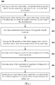
- FIG 1 is a flow chart of a method for transmitting data by using a fixed ground balise according to an aspect of the present disclosure.
- An aspect of the present disclosure provides a method 100 for transmitting data by using a fixed ground balise. As shown in FIG 1 , the method 100 starts from step S101:
- the method includes:
- the method includes:
- the method includes: Receiving the modulated vehicle running control data by the onboard balise through a second antenna unit, to control running of a vehicle according to the received vehicle running control data.
- the method further includes: Arranging a capacitor at the first antenna unit, arranging a magnetic bead connected with the capacitor to extract a voltage at both ends of the capacitor, carrying out bridge rectification by a diode, and limiting an amplitude of the received carrier frequency signal within a preset range.
- the amplitude of the received carrier frequency signal is limited within the preset range by the amplitude limitation circuit.
- the present application is exemplarily illustrated by taking an alternating current amplitude limitation circuit as an example, but is not limited to the alternating current.
- the alternating current amplitude limitation circuit includes: a tuning capacitor arranged at corner of the antenna; and a magnetic bead connected with the tuning capacitor and used for extracting a voltage of both ends of the tuning capacitor.
- the magnetic bead is of a parallel structure. A Schottky diode connected with the magnetic bead is used for carrying out bridge rectification of the extracted voltage.
- each bridge arm of the Schottky diode includes a plurality of diodes.
- each bridge arm of the Schottky diode includes four diodes, and a triode which is used for clamping the rectified voltage; and when the voltage at both ends of the tuning capacitor is excessively high, the Schottky diode is conducted, charges are discharged for both ends of the tuning capacitor by the triode, and meanwhile an impedance of the magnetic bead is connected in series; and the balise provided by the present disclosure further includes an overvoltage protection module connected with the tuning capacitor of an alternating current amplitude limitation module.
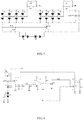
- FIG 3 is a structural schematic diagram of the alternating current amplitude limitation circuit in the method for transmitting data by using the switchable ground balise according to the embodiment of the present disclosure.
- the tuning capacitors on four corners of the antenna are all connected with overvoltage protection circuits, and the overvoltage protection circuits have consistent structures and parameters, and thus, only the overvoltage protection circuits connected with both sides of a capacitor C116 are selected.
- the voltages at both ends of the capacitor is extracted by the magnetic bead, the magnetic bead uses a parallel structure to improve a flow rate, bridge rectification is carried out by the Schottky diode after the voltage is extracted, and each bridge arm uses four diodes to improve the flow rate.
- T46 and T47 as reference potentials, the rectified direct current voltage is clamped by a triode T, and when the voltage at both ends of the capacitor is excessively high, a rectifier tube is conducted, charges are discharged for both ends of the capacitor by the triode T, and it is equivalent to change capacitive reactance of the capacitor and meanwhile the impedance of the magnetic bead is connected in series.
- the method further includes: Arranging the capacitor at the first antenna unit, and connecting an overvoltage protection unit with the capacitor so as to control the voltage within a safety voltage range.
- the voltage is controlled within the safety voltage range by the overvoltage protection circuit.
- FIG. 4 is a structural schematic diagram of the overvoltage protection circuit in the method for transmitting data by using the switchable ground balise according to the embodiment of the present disclosure.
- the overvoltage protection circuit includes a filter capacitor. When a read-write operation is carried out, the overvoltage protection circuit connects the filter capacitor in series into a power circuit.
- VCCO Voltage Controlled Crystal Oscillator
- CPLD Complex Programmable Logic Device
- FIG. 2 is a flow chart of a method for transmitting data by using an switchable ground balise according to an aspect of the present disclosure. As shown in FIG. 2 , the method 200 for transmitting data by using the switchable ground balise includes:
- the method 200 further includes:
- the method 200 further includes: Providing a communication connection with the LEU;
- the method 200 further includes: Receiving the modulated vehicle running control data by the onboard balise through a second antenna unit, to control running of a vehicle according to the received vehicle running control data.
- the method 200 further includes: Arranging a capacitor at the first antenna unit, arranging a magnetic bead connected with the capacitor to extract a voltage at both ends of the capacitor, carrying out bridge rectification by a diode, and limiting an amplitude of the received carrier frequency signal within a preset range.
- the amplitude of the received carrier frequency signal is limited within the preset range by an alternating current amplitude limitation circuit.
- the alternating current amplitude limitation circuit includes: a tuning capacitor arranged at corner of the antenna; and a magnetic bead connected with the tuning capacitor and used for extracting a voltage of both ends of the tuning capacitor.
- the magnetic bead is of a parallel structure.
- a Schottky diode connected with the magnetic bead is used for carrying out bridge rectification on the extracted voltage.
- each bridge arm of the Schottky diode includes a plurality of diodes.
- each bridge arm of the Schottky diode includes four diodes, and a triode which is used for clamping the rectified voltage; and when the voltage at both ends of the tuning capacitor is excessively high, the Schottky diode is conducted, charges are discharged for both ends of the tuning capacitor by the triode, and meanwhile an impedance of the magnetic bead is connected in series; and the balise provided by the present disclosure further includes an overvoltage protection module connected with the tuning capacitor of an alternating current amplitude limitation module.
- the structural schematic diagram of the alternating current amplitude limitation circuit refers to description in FIG. 3 , and is not repeated herein.
- the method 200 further includes: Arranging the capacitor at the first antenna unit, and connecting an overvoltage protection unit with the capacitor so as to control the voltage within a safety voltage range.
- the voltage is controlled within the safety voltage range by the overvoltage protection circuit.
- two sets of overvoltage protection circuits are arranged.
- the overvoltage protection circuit includes a filter capacitor. When the read-write operation is carried out, the overvoltage protection circuit connects the filter capacitor in series into a power circuit.
- the structural schematic diagram of the overvoltage protection circuit in the present application is as shown in FIG. 4 , and is not repeated herein.
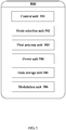
- FIG. 5 is a structural schematic diagram of a fixed ground balise according to an aspect of the present disclosure. As shown in FIG. 5 , the fixed ground balise 500 includes:
- the fixed ground balise further includes: An alternating current amplitude limitation unit, which is used for arranging a capacitor at the first antenna unit, arranging a magnetic bead connected with the capacitor to extract a voltage at both ends of the capacitor, carrying out bridge rectification by a diode, and limiting an amplitude of the received carrier frequency signal within a preset range.
- An alternating current amplitude limitation unit which is used for arranging a capacitor at the first antenna unit, arranging a magnetic bead connected with the capacitor to extract a voltage at both ends of the capacitor, carrying out bridge rectification by a diode, and limiting an amplitude of the received carrier frequency signal within a preset range.
- the fixed ground balise further includes: An overvoltage protection unit, which is used for arranging the capacitor at the first antenna unit, the overvoltage protection unit being connected with the capacitor for controlling the voltage within a safety voltage range.
- the mode selection unit is further used for: when the vehicle running control data stored in the data storage unit needs to be modified, proceeding to the updating mode according to the received instruction of the control unit so as to modify the vehicle running control data; and
- the fixed ground balise 500 according to the aspect of the present disclosure corresponds to the method 100 for transmitting data by using the fixed ground balise according to another aspect of the present disclosure, and is not repeated herein.
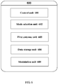
- FIG. 6 is a structural schematic diagram of an switchable ground balise according to an aspect of the present disclosure. As shown in FIG 6 , the switchable ground balise 600 includes:
- the switchable ground balise further includes: An alternating current amplitude limitation unit, which is used for arranging a capacitor at the first antenna unit, arranging a magnetic bead connected with the capacitor to extract a voltage at both ends of the capacitor, carrying out bridge rectification by a diode, and limiting an amplitude of the received carrier frequency signal within a preset range.
- the switchable ground balise further includes: An overvoltage protection unit, which is used for arranging the capacitor at the first antenna unit, the overvoltage protection unit being connected with the capacitor for controlling the voltage within a safety voltage range.
- the fixed ground balise 500 according to the aspect of the present disclosure corresponds to the method 100 for transmitting data by using the fixed ground balise according to another aspect of the present disclosure, and is not repeated herein.
Landscapes
- Engineering & Computer Science (AREA)
- Computer Networks & Wireless Communication (AREA)
- Signal Processing (AREA)
- Mechanical Engineering (AREA)
- Electric Propulsion And Braking For Vehicles (AREA)
- Train Traffic Observation, Control, And Security (AREA)
- Near-Field Transmission Systems (AREA)
- Radio Relay Systems (AREA)
- Communication Control (AREA)
Description
- The present disclosure relates to a field of communications technology, and more particularly, to a fixed ground balise, a switchable ground balise and corresponding methods.
- A balise is intermittent dvice for information transmission from the ground to a train, and includes a fixed balise and a controlled (switchable) balise. The balise has the main application of providing reliable ground fixed information and variable information to Automatic Train Protection (ATP) onboard equipment. The balise is transmission equipment capable of sending telegram information to an onboard subsystem, and not only can transmit the fixed information, but also can be connected with a trackside unit to transmit the variable information. Balise equipment transmits information to the ATP onboard equipment, including: basic line parameters, such as line gradient, track section and the like; line speed information, such as maximum line permissive speed, maximum train permissive speed and the like; temporary speed restriction information, i.e., when a train running speed is restricted due to reasons of construction and the like, the temporary speed restriction information is provided to the train; station route information, i.e., according to a station train arrival and departure route, parameters of "line gradient", "line speed", "track section" and the like are provided to the train; switch information, i.e., a lateral train running permissive speed of a front switch is given out; special positioning information, such as lifting bow, access of a tunnel, whistling, train positioning and the like; and other information, such as fixed obstacle information, train running target data, linking data and the like.
- The fixed balise is used for sending fixed data and is used for providing the line fixed parameters, e.g., the line gradient, the line permissive speed, track circuit parameters, linking information, train control level switching and the like.
- The switchable balise is used for transmitting variable information. The switchable balise needs to be connected with Lineside Electronic Unit (LEU) equipment by a special balise cable, and can variably transmit balise telegram information to the train according to a telegram sent by the LEU equipment. The switchable balise is connected with an LEU for sending a telegram from the LEU, and in an existing line speed-up section, the switchable balise is arranged at an inbound end and an outbound section of a station and mainly sends the route information and the temporary speed restriction information.
- Whether the fixed balise or the switchable balise has the same working principle. When the train passes through a position above the ground balise, after the balise receives electromagnetic energy sent by an intermittent information receiving antenna of the ATP onboard equipment, the balise can convert the energy into a working power, start up an electronic circuit to work and cyclically send out a 1023-bit balise transmission telegram which is pre-stored or transmitted by the LEU, until the electromagnetic energy disappears.
- The balise equipment can be simply understood as a data storage and a sender, and when an onboard antenna activates the balise, the balise sends a balise telegram stored by the balise or a balise telegram transmitted by the LEU. Authenticity and validity of stored data and transmitted data of the balise are very important for safe running of a vehicle.
- Therefore, a technology is required to enable the fixed or switchable ground balise to perform authentic and valid transmission of data.
-
CN 205 706 707 U aims to disclose a transponder system with a controllable message output, a controllable transponder and a transponder reader/writer. The transponder system with controllable message output includes a controllable transponder and a transponder reader; the transponder reader is used to write message data and/or switch instructions to the controllable transponder; the switch instructions control the drive to be in an open state or a closed state. -
CN 102 237 891 A aims to disclose a transponder ground equipment, which comprises a passive transponder, an active transponder and a ground electronic unit, wherein the passive transponder is used for transmitting fixed data information, the active transponder is used for transmitting real-time data information; and the ground electronic unit is connected with the active transponder, and is used for providing the real-time data information for the active transponder. - The present disclosure provides a fixed ground balise, a switchable ground balise and corresponding methods for transmitting data by using fixed and switchable ground balises, so as to solve a problem how to provide reliable ground fixed information and variable information for ATP onboard equipment.
- In order to solve the above-mentioned problem, the present disclosure provides a method for transmitting data by using a fixed ground balise. The method includes:
- Receiving an instruction of proceeding to an updating mode and receiving the updating data for vehicle running control data from a control unit by the fixed ground balise;
- Modifying the vehicle running control data in a data storage unit according to the updating data, and storing the updated vehicle running control data to the data storage unit;
- Receiving an instruction of proceeding to a working mode from the control unit;
- Carrying out Frequency Shift Keying (FSK) modulation on the vehicle running control data by a modulation unit to obtain the modulated vehicle running control data;
- Receiving a carrier frequency signal from onboard equipment by utilizing a first antenna unit;
- Converting energy of the carrier frequency signal into a working power of the ground balise; and
- Sending the modulated vehicle running control data to an onboard balise of the onboard equipment by the ground balise through utilizing the first antenna unit wherein the vehicle running control data is control data for running a vehicle.
- Wherein the method further includes arranging a capacitor at the first antenna unit, arranging a magnetic bead connected with the capacitor to extract a voltage at both ends of the capacitor, carrying out bridge rectification by a diode, and limiting an amplitude of the received carrier frequency signal within a preset range.
- On the basis of another aspect of the present disclosure, there is provided a method for transmitting data by using a switchable ground balise. The method includes:
- Receiving an instruction of proceeding to an updating mode from a control unit by the switchable ground balise;
- Receiving updating data for vehicle running control data from an LEU by the switchable ground balise;
- Carrying out FSK modulation on the vehicle running control data by a modulation unit to obtain the modulated vehicle running control data;
- Receiving a carrier frequency signal from onboard equipment by utilizing a first antenna unit; and
- Sending the modulated vehicle running control data to an onboard balise of the onboard equipment by the ground balise through utilizing the first antenna unit wherein the vehicle running control data is control data for running a vehicle.
- Wherein, the method further includes:
Arranging a capacitor at the first antenna unit, arranging a magnetic bead connected with the capacitor to extract a voltage at both ends of the capacitor, carrying out bridge rectification by a diode, and limiting an amplitude of the received carrier frequency signal within a preset range. - In one embodiment, the method further includes:
Arranging the capacitor at the first antenna unit, and connecting an overvoltage protection unit with the capacitor so as to control the voltage within a safety voltage range. - In one embodiment, the method includes:
- When the vehicle running control data stored in the data storage unit needs to be modified, proceeding to the updating mode according to the received instruction of the control unit so as to modify the vehicle running control data; and
- When the vehicle running control data stored in the data storage unit needs to be sent, proceeding to the working mode according to the received instruction of the control unit so as to send the vehicle running control data.
- In one embodiment, the method includes:
- Providing a communication connection with the LEU; and
- Converting Differential Bi Phase Level (DBPL) coded information which is received by the LEU and exceeds a conventional digital transmission limit into the vehicle running control data of the ground balise.
- In one embodiment, the method includes:
Receiving the modulated vehicle running control data by the onboard balise through a second antenna unit, to control running of a vehicle according to the received vehicle running control data. - On the basis of yet another aspect of the present disclosure, there is provided a fixed ground balise. The fixed ground balise includes:
- A control unit, which is used for receiving an instruction of proceeding to an updating mode; and receiving an instruction of proceeding to a working mode;
- A mode selection unit, which is used for enabling the fixed ground balise to select to proceed to the updating mode or the working mode according to the received instruction of the control unit;
- A first antenna unit, the fixed ground balise receiving updating data for vehicle running control data through the first antenna unit; a carrier frequency signal being received from onboard equipment by utilizing the first antenna unit; and the fixed ground balise sending the modulated vehicle running control data to an onboard balise of the onboard equipment by utilizing the first antenna unit;
- A power unit, which is used for converting energy of the carrier frequency signal into a working power of the ground balise;
- A data storage unit, which is used for modifying the vehicle running control data in the data storage unit according to the updating data and storing the updated vehicle running control data to the data storage unit; and
- A modulation unit, which is used for carrying out FSK modulation of the vehicle running control data to obtain the modulated vehicle running control data wherein the vehicle running control data is control data for running a vehicle.
- On the basis of still a further aspect of the present disclosure, there is provided an switchable ground balise. The switchable ground balise includes:
- A control unit, which is used for receiving an instruction of proceeding to an updating mode; and receiving an instruction of proceeding to a working mode;
- A mode selection unit, which is used for enabling the switchable ground balise to select to proceed to the updating mode or the working mode according to the received instruction of the control unit;
- A first antenna unit, the switchable ground balise receiving updating data for vehicle running control data from an LEU through the first antenna unit; a carrier frequency signal being received from onboard equipment by utilizing the first antenna unit; and the switchable ground balise sending the modulated vehicle running control data to an onboard balise of the onboard equipment by utilizing the first antenna unit;
- A data storage unit, which is used for modifying the vehicle running control data in the data storage unit according to the updating data and storing the updated vehicle running control data to the data storage unit; and
- A modulation unit, which is used for carrying out FSK modulation of the vehicle running control data to obtain the modulated vehicle running control data wherein the vehicle running control data is control data for running a vehicle.
- Wherein, the fixed ground balise further includes:
An amplitude limitation unit, which is used for arranging a capacitor at the first antenna unit, arranging a magnetic bead connected with the capacitor to extract a voltage at both ends of the capacitor, carrying out bridge rectification by a diode, and limiting an amplitude of the received carrier frequency signal within a preset range. - Wherein, the switchable ground balise further includes:
An amplitude limitation unit, which is used for arranging a capacitor at the first antenna unit, arranging a magnetic bead connected with the capacitor to extract a voltage at both ends of the capacitor, carrying out bridge rectification by a diode, and limiting an amplitude of the received carrier frequency signal within a preset range. - In one embodiment, the fixed ground balise further includes:
An overvoltage protection unit, which is used for arranging the capacitor at the first antenna unit, the overvoltage protection unit being connected with the capacitor for controlling the voltage within a safety voltage range. - In one embodiment, the switchable ground balise further includes:
An overvoltage protection unit, which is used for arranging the capacitor at the first antenna unit, the overvoltage protection unit being connected with the capacitor for controlling the voltage within a safety voltage range. - In one embodiment, the mode selection unit is further used for: when the vehicle running control data stored in the data storage unit needs to be modified, proceeding to the updating mode according to the received instruction of the control unit so as to modify the vehicle running control data; and
When the vehicle running control data stored in the data storage unit needs to be sent, proceeding to the working mode according to the received instruction of the control unit so as to send the vehicle running control data. - In one embodiment, the switchable ground balise further includes:
An interface unit, which is used for providing a communication connection with the LEU; and - A data conversion unit, which is used for converting DBPL coded information which is received by the LEU and exceeds a conventional digital transmission limit into the vehicle running control data of the ground balise.
- The method for transmitting data by using the fixed ground balise or the switchable ground balise, as provided by the technical solution of the present disclosure, can meet the requirements of the onboard equipment and accurately send effective data information and can more effectively ensure running safety of the vehicle.
- With reference to the drawings below, the exemplary embodiments of the present disclosure can be more completely understood:
-
FIG 1 is a flow chart of a method for transmitting data by using a fixed ground balise according to an aspect of the present disclosure; -
FIG 2 is a flow chart of a method for transmitting data by using an switchable ground balise according to an aspect of the present disclosure; -
FIG 3 is a structural schematic diagram of an alternating current amplitude limitation circuit in the method for transmitting data by using the switchable ground balise according to the embodiment of the present disclosure; -
FIG 4 is a structural schematic diagram of an overvoltage protection circuit in the method for transmitting data by using the switchable ground balise according to the embodiment of the present disclosure; -
FIG. 5 is a structural schematic diagram of a fixed ground balise according to an aspect of the present disclosure; and -
FIG 6 is a structural schematic diagram of an switchable ground balise according to an aspect of the present disclosure. - Now exemplary embodiments of the present disclosure are illustrated with reference to the drawings, but the present disclosure can be implemented in many different forms and not limited to the embodiments described herein, and providing those embodiments is to completely disclose the present disclosure in detail and fully convey the scope of the present disclosure to those skilled in the art. Terms expressed in the exemplary embodiments in the drawings are not intended to limit the present disclosure. In the drawings, the same units/components use the same reference signs.
- Unless otherwise defined, the terms (including technical and scientific terms) here should be of general meaning as understood by those skilled in the art. In addition, it can be understood that terms defined by commonly-used dictionaries should be understood to have consistent meanings with contents in the fields related thereto, but not be understood as idealized or too formal meanings.
-
FIG 1 is a flow chart of a method for transmitting data by using a fixed ground balise according to an aspect of the present disclosure. An aspect of the present disclosure provides amethod 100 for transmitting data by using a fixed ground balise. As shown inFIG 1 , themethod 100 starts from step S101: - S101: the fixed ground balise receives an instruction of proceeding to an updating mode, and updating data for vehicle running control data from a control unit fixed;
- S102: modifying the vehicle running control data in a data storage unit according to the updating data, and storing the updated vehicle running control data to the data storage unit;
- S103: receiving an instruction of proceeding to a working mode from the control unit;
- S104: carrying out FSK modulation on the vehicle running control data by a modulation unit to obtain the modulated vehicle running control data;
- S105: receiving a carrier frequency signal from onboard equipment by utilizing a first antenna unit;
- S106: converting energy of the carrier frequency signal into a working power of the ground balise; and
- S107: sending the modulated vehicle running control data to an onboard balise of the onboard equipment by the ground balise through utilizing the first antenna unit.
- In one embodiment, the method includes:
- When the vehicle running control data stored in the data storage unit needs to be modified, proceeding to the updating mode according to the received instruction of the control unit so as to modify the vehicle running control data; and
- When the vehicle running control data stored in the data storage unit needs to be sent, proceeding to the working mode according to the received instruction of the control unit so as to send the vehicle running control data.
- In one embodiment, the method includes:
- Providing a communication connection with an LEU; and
- Converting DBPL coded information which is received by the LEU and exceeds a conventional digital transmission limit into the vehicle running control data of the ground balise.
- In one embodiment, the method includes:
Receiving the modulated vehicle running control data by the onboard balise through a second antenna unit, to control running of a vehicle according to the received vehicle running control data. - Wherein, the method further includes:
Arranging a capacitor at the first antenna unit, arranging a magnetic bead connected with the capacitor to extract a voltage at both ends of the capacitor, carrying out bridge rectification by a diode, and limiting an amplitude of the received carrier frequency signal within a preset range. - In the present application, the amplitude of the received carrier frequency signal is limited within the preset range by the amplitude limitation circuit. The present application is exemplarily illustrated by taking an alternating current amplitude limitation circuit as an example, but is not limited to the alternating current. In the present application, the alternating current amplitude limitation circuit includes: a tuning capacitor arranged at corner of the antenna; and a magnetic bead connected with the tuning capacitor and used for extracting a voltage of both ends of the tuning capacitor. In one embodiment of the present disclosure, the magnetic bead is of a parallel structure. A Schottky diode connected with the magnetic bead is used for carrying out bridge rectification of the extracted voltage. In one embodiment of the present disclosure, each bridge arm of the Schottky diode includes a plurality of diodes. In another embodiment of the present disclosure, each bridge arm of the Schottky diode includes four diodes, and a triode which is used for clamping the rectified voltage; and when the voltage at both ends of the tuning capacitor is excessively high, the Schottky diode is conducted, charges are discharged for both ends of the tuning capacitor by the triode, and meanwhile an impedance of the magnetic bead is connected in series; and the balise provided by the present disclosure further includes an overvoltage protection module connected with the tuning capacitor of an alternating current amplitude limitation module.
-
FIG 3 is a structural schematic diagram of the alternating current amplitude limitation circuit in the method for transmitting data by using the switchable ground balise according to the embodiment of the present disclosure. As shown inFIG. 3 , in the present application, the tuning capacitors on four corners of the antenna are all connected with overvoltage protection circuits, and the overvoltage protection circuits have consistent structures and parameters, and thus, only the overvoltage protection circuits connected with both sides of a capacitor C116 are selected. - The voltages at both ends of the capacitor is extracted by the magnetic bead, the magnetic bead uses a parallel structure to improve a flow rate, bridge rectification is carried out by the Schottky diode after the voltage is extracted, and each bridge arm uses four diodes to improve the flow rate. With T46 and T47 as reference potentials, the rectified direct current voltage is clamped by a triode T, and when the voltage at both ends of the capacitor is excessively high, a rectifier tube is conducted, charges are discharged for both ends of the capacitor by the triode T, and it is equivalent to change capacitive reactance of the capacitor and meanwhile the impedance of the magnetic bead is connected in series.
- Wherein, the method further includes:
Arranging the capacitor at the first antenna unit, and connecting an overvoltage protection unit with the capacitor so as to control the voltage within a safety voltage range. In the present application, the voltage is controlled within the safety voltage range by the overvoltage protection circuit. -
FIG. 4 is a structural schematic diagram of the overvoltage protection circuit in the method for transmitting data by using the switchable ground balise according to the embodiment of the present disclosure. In the present application, two sets of overvoltage protection circuits are arranged. In one embodiment of the present disclosure, the overvoltage protection circuit includes a filter capacitor. When a read-write operation is carried out, the overvoltage protection circuit connects the filter capacitor in series into a power circuit. - As shown in
FIG. 4 , two sets of overvoltage protection circuits are designed in the embodiment of the present application for redundant multiplexing. With T14 and T15 as reference potentials, a Voltage Controlled Crystal Oscillator (VCCO) is clamped by shunting of T23 so as to clamp the VCCO on 3.9V A +C end is connected to a coding Complex Programmable Logic Device (CPLD), when the read-write operation is carried out, T22 is conducted, capacitors C31 and C32 are connected in series into the circuit, and the filter capacitor is added. -
FIG. 2 is a flow chart of a method for transmitting data by using an switchable ground balise according to an aspect of the present disclosure. As shown inFIG. 2 , themethod 200 for transmitting data by using the switchable ground balise includes: - S201: the switchable ground balise receives an instruction of proceeding to an updating mode from a control unit;
- S202: the switchable ground balise receives updating data for vehicle running control data from an LEU;
- S203: carrying out FSK modulation on the vehicle running control data by a modulation unit to obtain the modulated vehicle running control data;
- S204: receiving a carrier frequency signal from onboard equipment by utilizing a first antenna unit; and
- S205: sending the modulated vehicle running control data to an onboard balise of the onboard equipment by the ground balise through utilizing the first antenna unit.
- In one embodiment, the
method 200 further includes: - When the vehicle running control data stored in the data storage unit needs to be modified, proceeding to the updating mode according to the received instruction of the control unit so as to modify the vehicle running control data; and
- When the vehicle running control data stored in the data storage unit needs to be sent, proceeding to the working mode according to the received instruction of the control unit so as to send the vehicle running control data.
- In one embodiment the
method 200 further includes:
Providing a communication connection with the LEU; - Converting DBPL coded information which is received by the LEU and exceeds a conventional digital transmission limit into the vehicle running control data of the ground balise.
- In one embodiment, the
method 200 further includes:
Receiving the modulated vehicle running control data by the onboard balise through a second antenna unit, to control running of a vehicle according to the received vehicle running control data. - Wherein, the
method 200 further includes:
Arranging a capacitor at the first antenna unit, arranging a magnetic bead connected with the capacitor to extract a voltage at both ends of the capacitor, carrying out bridge rectification by a diode, and limiting an amplitude of the received carrier frequency signal within a preset range. - In the present application, the amplitude of the received carrier frequency signal is limited within the preset range by an alternating current amplitude limitation circuit. In the present application, the alternating current amplitude limitation circuit includes: a tuning capacitor arranged at corner of the antenna; and a magnetic bead connected with the tuning capacitor and used for extracting a voltage of both ends of the tuning capacitor. In one embodiment of the present disclosure, the magnetic bead is of a parallel structure. A Schottky diode connected with the magnetic bead is used for carrying out bridge rectification on the extracted voltage. In one embodiment of the present disclosure, each bridge arm of the Schottky diode includes a plurality of diodes. In another embodiment of the present disclosure, each bridge arm of the Schottky diode includes four diodes, and a triode which is used for clamping the rectified voltage; and when the voltage at both ends of the tuning capacitor is excessively high, the Schottky diode is conducted, charges are discharged for both ends of the tuning capacitor by the triode, and meanwhile an impedance of the magnetic bead is connected in series; and the balise provided by the present disclosure further includes an overvoltage protection module connected with the tuning capacitor of an alternating current amplitude limitation module. The structural schematic diagram of the alternating current amplitude limitation circuit refers to description in
FIG. 3 , and is not repeated herein. - In one embodiment, the
method 200 further includes:
Arranging the capacitor at the first antenna unit, and connecting an overvoltage protection unit with the capacitor so as to control the voltage within a safety voltage range. In the present application, the voltage is controlled within the safety voltage range by the overvoltage protection circuit. In the present application, two sets of overvoltage protection circuits are arranged. In one embodiment of the present disclosure, the overvoltage protection circuit includes a filter capacitor. When the read-write operation is carried out, the overvoltage protection circuit connects the filter capacitor in series into a power circuit. The structural schematic diagram of the overvoltage protection circuit in the present application is as shown inFIG. 4 , and is not repeated herein. -
FIG. 5 is a structural schematic diagram of a fixed ground balise according to an aspect of the present disclosure. As shown inFIG. 5 , the fixed ground balise 500 includes: - A
control unit 501, which is used for receiving an instruction of proceeding to an updating mode; and receiving an instruction of proceeding to a working mode; - A
mode selection unit 502, which is used for enabling the fixed ground balise to select to proceed to the updating mode or the working mode according to the received instruction of the control unit; - A
first antenna unit 503, the fixed ground balise receiving updating data for vehicle running control data through the first antenna unit; a carrier frequency signal being received from onboard equipment by utilizing the first antenna unit; and the fixed ground balise sending the modulated vehicle running control data to an onboard balise of the onboard equipment by utilizing the first antenna unit; - A
power unit 504, which is used for converting energy of the carrier frequency signal into a working power of the ground balise; - A
data storage unit 505, which is used for modifying the vehicle running control data in the data storage unit according to the updating data and storing the updated vehicle running control data to the data storage unit; and - A
modulation unit 506, which is used for carrying out FSK modulation of the vehicle running control data to obtain the modulated vehicle running control data. - Wherein, the fixed ground balise further includes:
An alternating current amplitude limitation unit, which is used for arranging a capacitor at the first antenna unit, arranging a magnetic bead connected with the capacitor to extract a voltage at both ends of the capacitor, carrying out bridge rectification by a diode, and limiting an amplitude of the received carrier frequency signal within a preset range. - In one embodiment, the fixed ground balise further includes:
An overvoltage protection unit, which is used for arranging the capacitor at the first antenna unit, the overvoltage protection unit being connected with the capacitor for controlling the voltage within a safety voltage range. - In one embodiment, the mode selection unit is further used for: when the vehicle running control data stored in the data storage unit needs to be modified, proceeding to the updating mode according to the received instruction of the control unit so as to modify the vehicle running control data; and
- When the vehicle running control data stored in the data storage unit needs to be sent, proceeding to the working mode according to the received instruction of the control unit so as to send the vehicle running control data.
- The fixed ground balise 500 according to the aspect of the present disclosure corresponds to the
method 100 for transmitting data by using the fixed ground balise according to another aspect of the present disclosure, and is not repeated herein. -
FIG. 6 is a structural schematic diagram of an switchable ground balise according to an aspect of the present disclosure. As shown inFIG 6 , the switchable ground balise 600 includes: - A
control unit 601, which is used for receiving an instruction of proceeding to an updating mode; and receiving an instruction of proceeding to a working mode; - A
mode selection unit 602, which is used for enabling the switchable ground balise to select to proceed to the updating mode or the working mode according to the received instruction of the control unit; - A
first antenna unit 603, the switchable ground balise receiving updating data for vehicle running control data from an LEU through the first antenna unit; a carrier frequency signal being received from onboard equipment by utilizing the first antenna unit; and the switchable ground balise sending the modulated vehicle running control data to an onboard balise of the onboard equipment by utilizing the first antenna unit; - A
data storage unit 604, which is used for modifying the vehicle running control data in the data storage unit according to the update data and storing the updated vehicle running control data to the data storage unit; and - A
modulation unit 605, which is used for carrying out FSK modulation of the vehicle running control data to obtain the modulated vehicle running control data. - Wherein, the switchable ground balise further includes:
An alternating current amplitude limitation unit, which is used for arranging a capacitor at the first antenna unit, arranging a magnetic bead connected with the capacitor to extract a voltage at both ends of the capacitor, carrying out bridge rectification by a diode, and limiting an amplitude of the received carrier frequency signal within a preset range. - In one embodiment, the switchable ground balise further includes:
An overvoltage protection unit, which is used for arranging the capacitor at the first antenna unit, the overvoltage protection unit being connected with the capacitor for controlling the voltage within a safety voltage range. - In one embodiment the switchable ground balise further includes:
- An interface unit, which is used for providing a communication connection with the LEU; and
- A data conversion unit, which is used for converting DBPL coded information which is received by the LEU and exceeds a conventional digital transmission limit into the vehicle running control data of the ground balise.
- The fixed ground balise 500 according to the aspect of the present disclosure corresponds to the
method 100 for transmitting data by using the fixed ground balise according to another aspect of the present disclosure, and is not repeated herein. - The present disclosure has been described with reference to a few embodiments. However, those skilled in the art commonly know that as defined by the appended claims, besides the above-disclosed embodiments of the present disclosure, other embodiments equivalently fall within the scope of the present disclosure.
- Generally, all terms used in the claims are explained according to general meanings in the art, unless otherwise defined. All the references "a/the above-mentioned/the [device, component and the like]" are openly explained as at least one example in the device, component and the like, unless otherwise defined. The steps of any methods disclosed herein are all necessary to execute according to the disclosed accurate sequence, unless otherwise defined.
Claims (12)
- A method for transmitting data by using a fixed ground balise, comprising:receiving (101) an instruction of proceeding to an updating mode and updating data for vehicle running control data from a control unit by the fixed ground balise;modifying (102) the vehicle running control data in a data storage unit according to the updating data, and storing the updated vehicle running control data to the data storage unit;receiving (103) an instruction of proceeding to a working mode by the control unit;carrying out (104) Frequency Shift Keying, FSK, modulation of the vehicle running control data by a modulation unit to obtain the modulated vehicle running control data;receiving (105) a carrier frequency signal from onboard equipment by utilizing a first antenna unit;converting (106) energy of the carrier frequency signal into a working power of the ground balise; andsending (107) the modulated vehicle running control data to an onboard balise of the onboard equipment by the ground balise through utilizing the first antenna unit;wherein the vehicle running control data is control data for running a vehicle;characterized by arranging a capacitor at the first antenna unit, arranging a magnetic bead connected with the capacitor to extract a voltage at both ends of the capacitor, carrying out bridge rectification by a diode, and limiting an amplitude of the received carrier frequency signal within a preset range.
- A method for transmitting data by using a switchable ground balise, comprising:receiving (201) an instruction of proceeding to an updating mode from a control unit by the switchable ground balise;receiving (202) updating data for vehicle running control data from a Lineside Electronic Unit, LEU, by the switchable ground balise;carrying out (203) FSK modulation of the vehicle running control data by a modulation unit to obtain the modulated vehicle running control data;receiving (204) a carrier frequency signal from onboard equipment by utilizing a first antenna unit; andsending (205) the modulated vehicle running control data to an onboard balise of the onboard equipment by the ground balise through utilizing the first antenna unit;wherein the vehicle running control data is control data for running a vehicle;characterized by arranging a capacitor at the first antenna unit, arranging a magnetic bead connected with the capacitor to extract a voltage at both ends of the capacitor, carrying out bridge rectification by a diode, and limiting an amplitude of the received carrier frequency signal within a preset range.
- The method according to claim 1 or 2, further comprising:
arranging the capacitor at the first antenna unit, and connecting an overvoltage protection unit with the capacitor so as to control the voltage within a safety voltage range. - The method according to claim 1, comprising:when the vehicle running control data stored in the data storage unit needs to be modified, proceeding to the updating mode according to the received instruction of the control unit so as to modify the vehicle running control data; andwhen the vehicle running control data stored in the data storage unit needs to be sent, proceeding to the working mode according to the received instruction of the control unit so as to send the vehicle running control data.
- The method according to claim 2, comprising:providing a communication connection with the LEU;converting Differential Bi Phase Level, DBPL, coded information which is received by the LEU and exceeds a conventional digital transmission limit into the vehicle running control data of the ground balise.
- The method according to claim 1 or 2, comprising:
receiving the modulated vehicle running control data by the onboard balise through a second antenna unit, to control running of a vehicle according to the received vehicle running control data. - A fixed ground balise, comprising:a control unit, which is used for receiving an instruction of proceeding to an updating mode and receiving an instruction of proceeding to a working mode;a mode selection unit, which is used for enabling the fixed ground balise to select to proceed to the updating mode or the working mode according to the received instruction of the control unit;a first antenna unit, the fixed ground balise receiving updating data of vehicle running control data through the first antenna unit, a carrier frequency signal being received from onboard equipment by utilizing the first antenna unit, and the fixed ground balise sending the modulated vehicle running control data to an onboard balise of the onboard equipment by utilizing the first antenna unit;a power unit, which is used for converting energy of the carrier frequency signal into a working power of the ground balise;a data storage unit, which is used for modifying the vehicle running control data in the data storage unit according to the updating data and storing the updated vehicle running control data to the data storage unit; anda modulation unit, which is used for carrying out FSK modulation of the vehicle running control data to obtain the modulated vehicle running control data;wherein the vehicle running control data is control data for running a vehicle;characterized by an amplitude limitation unit, which is used for arranging a capacitor at the first antenna unit, arranging a magnetic bead connected with the capacitor to extract a voltage at both ends of the capacitor, carrying out bridge rectification by a diode, and limiting an amplitude of the received carrier frequency signal within a preset range.
- A switchable ground balise, comprising:a control unit, which is used for receiving an instruction of proceeding to an updating mode and receiving an instruction of proceeding to a working mode;a mode selection unit, which is used for enabling the switchable ground balise to select to proceed to the updating mode or the working mode according to the received instruction of the control unit;a first antenna unit, the switchable ground balise receiving updating data for vehicle running control data from a Lineside Electronic Unit, LEU, through the first antenna unit, a carrier frequency signal being received from onboard equipment by utilizing the first antenna unit, and the switchable ground balise sending the modulated vehicle running control data to an onboard balise of the onboard equipment by utilizing the first antenna unit;a data storage unit, which is used for modifying the vehicle running control data in the data storage unit according to the updating data and storing the updated vehicle running control data to the data storage unit; anda modulation unit, which is used for carrying out FSK modulation of the vehicle running control data to obtain the modulated vehicle running control data;wherein the vehicle running control data is control data for running a vehicle;characterized by an amplitude limitation unit, which is used for arranging a capacitor at the first antenna unit, arranging a magnetic bead connected with the capacitor to extract a voltage at both ends of the capacitor, carrying out bridge rectification by a diode, and limiting an amplitude of the received carrier frequency signal within a preset range.
- The fixed ground balise according to claim 7, further comprising:
an overvoltage protection unit, which is used for arranging the capacitor at the first antenna unit, the overvoltage protection unit being connected with the capacitor for controlling the voltage within a safety voltage range. - The switchable ground balise according to claim 8, further comprising:
an overvoltage protection unit, which is used for arranging the capacitor at the first antenna unit, the overvoltage protection unit being connected with the capacitor for controlling the voltage within a safety voltage range. - The fixed ground balise according to claim 7 or 9, wherein the mode selection unit is further used for: when the vehicle running control data stored in the data storage unit needs to be modified, proceeding to the updating mode according to the received instruction of the control unit so as to modify the vehicle running control data; and
when the vehicle running control data stored in the data storage unit needs to be sent, proceeding to the working mode according to the received instruction of the control unit so as to send the vehicle running control data. - The switchable ground balise according to claim 8 or 10, further comprising:an interface unit, which is used for providing a communication connection with the LEU; anda data conversion unit, which is used for converting Differential Bi Phase Level, DBPL, coded information which is received by the LEU and exceeds a conventional digital transmission limit into the vehicle running control data of the ground balise.
Priority Applications (2)
| Application Number | Priority Date | Filing Date | Title |
|---|---|---|---|
| RS20211479A RS62637B1 (en) | 2017-10-20 | 2018-05-10 | Method and system for implementing data transmission using ground balise |
| HRP20211893TT HRP20211893T1 (en) | 2017-10-20 | 2018-05-10 | Method and system for implementing data transmission using ground balise |
Applications Claiming Priority (2)
| Application Number | Priority Date | Filing Date | Title |
|---|---|---|---|
| CN201710983389.XA CN107995136B (en) | 2017-10-20 | 2017-10-20 | Method and system for data transmission by using ground transponder |
| PCT/CN2018/086262 WO2019076039A1 (en) | 2017-10-20 | 2018-05-10 | Method and system for implementing data transmission using ground balise |
Publications (3)
| Publication Number | Publication Date |
|---|---|
| EP3591918A1 EP3591918A1 (en) | 2020-01-08 |
| EP3591918A4 EP3591918A4 (en) | 2020-07-01 |
| EP3591918B1 true EP3591918B1 (en) | 2021-09-15 |
Family
ID=62029880
Family Applications (1)
| Application Number | Title | Priority Date | Filing Date |
|---|---|---|---|
| EP18868646.3A Active EP3591918B1 (en) | 2017-10-20 | 2018-05-10 | Method and system for implementing data transmission using ground balise |
Country Status (6)
| Country | Link |
|---|---|
| EP (1) | EP3591918B1 (en) |
| CN (1) | CN107995136B (en) |
| HR (1) | HRP20211893T1 (en) |
| HU (1) | HUE056776T2 (en) |
| RS (1) | RS62637B1 (en) |
| WO (1) | WO2019076039A1 (en) |
Families Citing this family (3)
| Publication number | Priority date | Publication date | Assignee | Title |
|---|---|---|---|---|
| CN107995136B (en) * | 2017-10-20 | 2020-09-08 | 北京全路通信信号研究设计院集团有限公司 | Method and system for data transmission by using ground transponder |
| CN110336646B (en) * | 2019-07-26 | 2023-06-06 | 卡斯柯信号有限公司 | DBPL code stoping equipment and method suitable for LEU |
| CN114771604B (en) * | 2022-06-16 | 2022-09-30 | 中国铁道科学研究院集团有限公司通信信号研究所 | Vehicle-mounted equipment processing system and method suitable for multiple train control ground systems |
Family Cites Families (6)
| Publication number | Priority date | Publication date | Assignee | Title |
|---|---|---|---|---|
| CN102237891A (en) * | 2011-05-16 | 2011-11-09 | 北京全路通信信号研究设计院有限公司 | Transponder ground equipment |
| US20140103962A1 (en) * | 2012-10-11 | 2014-04-17 | Sl3J Systems S.A.R.L. | High-speed gate driver for power switches with reduced voltage ringing |
| US9606224B2 (en) * | 2014-01-14 | 2017-03-28 | Alstom Transport Technologies | Systems and methods for vehicle position detection |
| CN104724141B (en) * | 2015-04-01 | 2017-03-15 | 北京交通大学 | Vehicle-mounted noncontact transponder programming device and a kind of vehicle-mounted transponder programmed method |
| CN205706707U (en) * | 2016-03-23 | 2016-11-23 | 北京交大思诺科技股份有限公司 | Responder system, controlled transponder and the transponder read and write device that message output is controlled |
| CN107995136B (en) * | 2017-10-20 | 2020-09-08 | 北京全路通信信号研究设计院集团有限公司 | Method and system for data transmission by using ground transponder |
-
2017
- 2017-10-20 CN CN201710983389.XA patent/CN107995136B/en active Active
-
2018
- 2018-05-10 HU HUE18868646A patent/HUE056776T2/en unknown
- 2018-05-10 EP EP18868646.3A patent/EP3591918B1/en active Active
- 2018-05-10 RS RS20211479A patent/RS62637B1/en unknown
- 2018-05-10 HR HRP20211893TT patent/HRP20211893T1/en unknown
- 2018-05-10 WO PCT/CN2018/086262 patent/WO2019076039A1/en unknown
Also Published As
| Publication number | Publication date |
|---|---|
| EP3591918A4 (en) | 2020-07-01 |
| RS62637B1 (en) | 2021-12-31 |
| CN107995136A (en) | 2018-05-04 |
| HUE056776T2 (en) | 2022-03-28 |
| HRP20211893T1 (en) | 2022-03-04 |
| EP3591918A1 (en) | 2020-01-08 |
| WO2019076039A1 (en) | 2019-04-25 |
| CN107995136B (en) | 2020-09-08 |
Similar Documents
| Publication | Publication Date | Title |
|---|---|---|
| EP3591918B1 (en) | Method and system for implementing data transmission using ground balise | |
| CN101442335B (en) | Responder | |
| EP3451545A3 (en) | System to calibrate phase using system information | |
| CN102237891A (en) | Transponder ground equipment | |
| CN109353378A (en) | A kind of vehicle-mounted monitoring information transmission device of railway and its implementation | |
| CN110808755A (en) | Digital-analog compatible train tail locomotive radio station and implementation method thereof | |
| US5563589A (en) | Remote identification device | |
| CN103606740B (en) | Regulate the device of antenna array beam direction and phase place in rfid interrogator | |
| CN100593491C (en) | Information transmission method, system and apparatus for train | |
| EP3291129B1 (en) | Rfid transponder and method for supplying energy thereto | |
| CN209521698U (en) | The vehicle-mounted monitoring information transmission radio station of railway | |
| CN210518316U (en) | Train tail locomotive radio station supporting digital-analog switching | |
| CN107888228B (en) | Interface circuit, integrated circuit, method, system and program product for a transponder | |
| CN107959505A (en) | A kind of passive balise and its method based on FPGA processor | |
| CN102372013A (en) | Frequency-shift automatic block system | |
| CN102043977B (en) | Electronic tag for automatic identification of high-speed train | |
| CN201998825U (en) | Auto-passing phase-splitting control device and passing phase-splitting control system for multi-locomotive | |
| CN206099953U (en) | Passive transponder based on FPGA treater | |
| CN208423944U (en) | A kind of intelligent vehicle-carried wireless charging device | |
| FI107793B (en) | Apparatus and method of transmitting data by means of a signaling device and the signaling device used in such equipment | |
| CN206341238U (en) | A kind of modulator for AIS systems | |
| CN105577390A (en) | Integrated point mode balise antenna system based on interference cancellation algorithm | |
| CN104219184B (en) | A kind of methods, devices and systems for transmitting message information | |
| CN108011363B (en) | Overvoltage protection circuit and responder A interface protection circuit | |
| CN203563065U (en) | Transponder, on board reader-writer, and system transmitting information |
Legal Events
| Date | Code | Title | Description |
|---|---|---|---|
| REG | Reference to a national code |
Ref country code: HR Ref legal event code: TUEP Ref document number: P20211893 Country of ref document: HR |
|
| STAA | Information on the status of an ep patent application or granted ep patent |
Free format text: STATUS: THE INTERNATIONAL PUBLICATION HAS BEEN MADE |
|
| PUAI | Public reference made under article 153(3) epc to a published international application that has entered the european phase |
Free format text: ORIGINAL CODE: 0009012 |
|
| STAA | Information on the status of an ep patent application or granted ep patent |
Free format text: STATUS: REQUEST FOR EXAMINATION WAS MADE |
|
| 17P | Request for examination filed |
Effective date: 20191001 |
|
| AK | Designated contracting states |
Kind code of ref document: A1 Designated state(s): AL AT BE BG CH CY CZ DE DK EE ES FI FR GB GR HR HU IE IS IT LI LT LU LV MC MK MT NL NO PL PT RO RS SE SI SK SM TR |
|
| AX | Request for extension of the european patent |
Extension state: BA ME |
|
| A4 | Supplementary search report drawn up and despatched |
Effective date: 20200602 |
|
| RIC1 | Information provided on ipc code assigned before grant |
Ipc: B61L 23/00 20060101ALI20200526BHEP Ipc: B61L 3/00 20060101ALI20200526BHEP Ipc: H04L 27/12 20060101AFI20200526BHEP Ipc: B61L 25/00 20060101ALI20200526BHEP Ipc: G01S 1/00 20060101ALI20200526BHEP Ipc: B61L 27/00 20060101ALI20200526BHEP Ipc: H04L 27/14 20060101ALI20200526BHEP |
|
| DAV | Request for validation of the european patent (deleted) | ||
| DAX | Request for extension of the european patent (deleted) | ||
| STAA | Information on the status of an ep patent application or granted ep patent |
Free format text: STATUS: EXAMINATION IS IN PROGRESS |
|
| 17Q | First examination report despatched |
Effective date: 20210212 |
|
| GRAP | Despatch of communication of intention to grant a patent |
Free format text: ORIGINAL CODE: EPIDOSNIGR1 |
|
| STAA | Information on the status of an ep patent application or granted ep patent |
Free format text: STATUS: GRANT OF PATENT IS INTENDED |
|
| RIC1 | Information provided on ipc code assigned before grant |
Ipc: H04L 27/14 20060101ALI20210416BHEP Ipc: B61L 3/00 20060101ALI20210416BHEP Ipc: B61L 23/00 20060101ALI20210416BHEP Ipc: B61L 25/00 20060101ALI20210416BHEP Ipc: B61L 27/00 20060101ALI20210416BHEP Ipc: G01S 1/00 20060101ALI20210416BHEP Ipc: B61L 3/12 20060101ALI20210416BHEP Ipc: H04L 27/12 20060101AFI20210416BHEP |
|
| INTG | Intention to grant announced |
Effective date: 20210525 |
|
| GRAS | Grant fee paid |
Free format text: ORIGINAL CODE: EPIDOSNIGR3 |
|
| GRAA | (expected) grant |
Free format text: ORIGINAL CODE: 0009210 |
|
| STAA | Information on the status of an ep patent application or granted ep patent |
Free format text: STATUS: THE PATENT HAS BEEN GRANTED |
|
| AK | Designated contracting states |
Kind code of ref document: B1 Designated state(s): AL AT BE BG CH CY CZ DE DK EE ES FI FR GB GR HR HU IE IS IT LI LT LU LV MC MK MT NL NO PL PT RO RS SE SI SK SM TR |
|
| REG | Reference to a national code |
Ref country code: CH Ref legal event code: EP |
|
| REG | Reference to a national code |
Ref country code: DE Ref legal event code: R096 Ref document number: 602018023771 Country of ref document: DE |
|
| REG | Reference to a national code |
Ref country code: IE Ref legal event code: FG4D |
|
| REG | Reference to a national code |
Ref country code: AT Ref legal event code: REF Ref document number: 1431407 Country of ref document: AT Kind code of ref document: T Effective date: 20211015 |
|
| REG | Reference to a national code |
Ref country code: SE Ref legal event code: TRGR |
|
| REG | Reference to a national code |
Ref country code: LT Ref legal event code: MG9D |
|
| REG | Reference to a national code |
Ref country code: NL Ref legal event code: MP Effective date: 20210915 |
|
| PG25 | Lapsed in a contracting state [announced via postgrant information from national office to epo] |
Ref country code: FI Free format text: LAPSE BECAUSE OF FAILURE TO SUBMIT A TRANSLATION OF THE DESCRIPTION OR TO PAY THE FEE WITHIN THE PRESCRIBED TIME-LIMIT Effective date: 20210915 Ref country code: LT Free format text: LAPSE BECAUSE OF FAILURE TO SUBMIT A TRANSLATION OF THE DESCRIPTION OR TO PAY THE FEE WITHIN THE PRESCRIBED TIME-LIMIT Effective date: 20210915 Ref country code: BG Free format text: LAPSE BECAUSE OF FAILURE TO SUBMIT A TRANSLATION OF THE DESCRIPTION OR TO PAY THE FEE WITHIN THE PRESCRIBED TIME-LIMIT Effective date: 20211215 Ref country code: NO Free format text: LAPSE BECAUSE OF FAILURE TO SUBMIT A TRANSLATION OF THE DESCRIPTION OR TO PAY THE FEE WITHIN THE PRESCRIBED TIME-LIMIT Effective date: 20211215 |
|
| PG25 | Lapsed in a contracting state [announced via postgrant information from national office to epo] |
Ref country code: LV Free format text: LAPSE BECAUSE OF FAILURE TO SUBMIT A TRANSLATION OF THE DESCRIPTION OR TO PAY THE FEE WITHIN THE PRESCRIBED TIME-LIMIT Effective date: 20210915 Ref country code: GR Free format text: LAPSE BECAUSE OF FAILURE TO SUBMIT A TRANSLATION OF THE DESCRIPTION OR TO PAY THE FEE WITHIN THE PRESCRIBED TIME-LIMIT Effective date: 20211216 |
|
| REG | Reference to a national code |
Ref country code: HR Ref legal event code: T1PR Ref document number: P20211893 Country of ref document: HR |
|
| REG | Reference to a national code |
Ref country code: HU Ref legal event code: AG4A Ref document number: E056776 Country of ref document: HU |
|
| PG25 | Lapsed in a contracting state [announced via postgrant information from national office to epo] |
Ref country code: IS Free format text: LAPSE BECAUSE OF FAILURE TO SUBMIT A TRANSLATION OF THE DESCRIPTION OR TO PAY THE FEE WITHIN THE PRESCRIBED TIME-LIMIT Effective date: 20220115 Ref country code: SM Free format text: LAPSE BECAUSE OF FAILURE TO SUBMIT A TRANSLATION OF THE DESCRIPTION OR TO PAY THE FEE WITHIN THE PRESCRIBED TIME-LIMIT Effective date: 20210915 Ref country code: SK Free format text: LAPSE BECAUSE OF FAILURE TO SUBMIT A TRANSLATION OF THE DESCRIPTION OR TO PAY THE FEE WITHIN THE PRESCRIBED TIME-LIMIT Effective date: 20210915 Ref country code: PT Free format text: LAPSE BECAUSE OF FAILURE TO SUBMIT A TRANSLATION OF THE DESCRIPTION OR TO PAY THE FEE WITHIN THE PRESCRIBED TIME-LIMIT Effective date: 20220117 Ref country code: PL Free format text: LAPSE BECAUSE OF FAILURE TO SUBMIT A TRANSLATION OF THE DESCRIPTION OR TO PAY THE FEE WITHIN THE PRESCRIBED TIME-LIMIT Effective date: 20210915 Ref country code: NL Free format text: LAPSE BECAUSE OF FAILURE TO SUBMIT A TRANSLATION OF THE DESCRIPTION OR TO PAY THE FEE WITHIN THE PRESCRIBED TIME-LIMIT Effective date: 20210915 Ref country code: ES Free format text: LAPSE BECAUSE OF FAILURE TO SUBMIT A TRANSLATION OF THE DESCRIPTION OR TO PAY THE FEE WITHIN THE PRESCRIBED TIME-LIMIT Effective date: 20210915 Ref country code: EE Free format text: LAPSE BECAUSE OF FAILURE TO SUBMIT A TRANSLATION OF THE DESCRIPTION OR TO PAY THE FEE WITHIN THE PRESCRIBED TIME-LIMIT Effective date: 20210915 Ref country code: CZ Free format text: LAPSE BECAUSE OF FAILURE TO SUBMIT A TRANSLATION OF THE DESCRIPTION OR TO PAY THE FEE WITHIN THE PRESCRIBED TIME-LIMIT Effective date: 20210915 Ref country code: AL Free format text: LAPSE BECAUSE OF FAILURE TO SUBMIT A TRANSLATION OF THE DESCRIPTION OR TO PAY THE FEE WITHIN THE PRESCRIBED TIME-LIMIT Effective date: 20210915 |
|
| REG | Reference to a national code |
Ref country code: DE Ref legal event code: R097 Ref document number: 602018023771 Country of ref document: DE |
|
| REG | Reference to a national code |
Ref country code: HR Ref legal event code: ODRP Ref document number: P20211893 Country of ref document: HR Payment date: 20220503 Year of fee payment: 5 |
|
| PLBE | No opposition filed within time limit |
Free format text: ORIGINAL CODE: 0009261 |
|
| STAA | Information on the status of an ep patent application or granted ep patent |
Free format text: STATUS: NO OPPOSITION FILED WITHIN TIME LIMIT |
|
| PG25 | Lapsed in a contracting state [announced via postgrant information from national office to epo] |
Ref country code: DK Free format text: LAPSE BECAUSE OF FAILURE TO SUBMIT A TRANSLATION OF THE DESCRIPTION OR TO PAY THE FEE WITHIN THE PRESCRIBED TIME-LIMIT Effective date: 20210915 |
|
| 26N | No opposition filed |
Effective date: 20220616 |
|
| PG25 | Lapsed in a contracting state [announced via postgrant information from national office to epo] |
Ref country code: SI Free format text: LAPSE BECAUSE OF FAILURE TO SUBMIT A TRANSLATION OF THE DESCRIPTION OR TO PAY THE FEE WITHIN THE PRESCRIBED TIME-LIMIT Effective date: 20210915 |
|
| REG | Reference to a national code |
Ref country code: CH Ref legal event code: PL |
|
| REG | Reference to a national code |
Ref country code: BE Ref legal event code: MM Effective date: 20220531 |
|
| GBPC | Gb: european patent ceased through non-payment of renewal fee |
Effective date: 20220510 |
|
| PG25 | Lapsed in a contracting state [announced via postgrant information from national office to epo] |
Ref country code: MC Free format text: LAPSE BECAUSE OF FAILURE TO SUBMIT A TRANSLATION OF THE DESCRIPTION OR TO PAY THE FEE WITHIN THE PRESCRIBED TIME-LIMIT Effective date: 20210915 Ref country code: LU Free format text: LAPSE BECAUSE OF NON-PAYMENT OF DUE FEES Effective date: 20220510 Ref country code: LI Free format text: LAPSE BECAUSE OF NON-PAYMENT OF DUE FEES Effective date: 20220531 Ref country code: IT Free format text: LAPSE BECAUSE OF FAILURE TO SUBMIT A TRANSLATION OF THE DESCRIPTION OR TO PAY THE FEE WITHIN THE PRESCRIBED TIME-LIMIT Effective date: 20210915 Ref country code: CH Free format text: LAPSE BECAUSE OF NON-PAYMENT OF DUE FEES Effective date: 20220531 |
|
| REG | Reference to a national code |
Ref country code: AT Ref legal event code: UEP Ref document number: 1431407 Country of ref document: AT Kind code of ref document: T Effective date: 20210915 |
|
| PG25 | Lapsed in a contracting state [announced via postgrant information from national office to epo] |
Ref country code: IE Free format text: LAPSE BECAUSE OF NON-PAYMENT OF DUE FEES Effective date: 20220510 |
|
| REG | Reference to a national code |
Ref country code: HR Ref legal event code: ODRP Ref document number: P20211893 Country of ref document: HR Payment date: 20230505 Year of fee payment: 6 |
|
| PG25 | Lapsed in a contracting state [announced via postgrant information from national office to epo] |
Ref country code: GB Free format text: LAPSE BECAUSE OF NON-PAYMENT OF DUE FEES Effective date: 20220510 Ref country code: BE Free format text: LAPSE BECAUSE OF NON-PAYMENT OF DUE FEES Effective date: 20220531 |
|
| PGFP | Annual fee paid to national office [announced via postgrant information from national office to epo] |
Ref country code: SE Payment date: 20230308 Year of fee payment: 6 |
|
| PGFP | Annual fee paid to national office [announced via postgrant information from national office to epo] |
Ref country code: RS Payment date: 20230510 Year of fee payment: 6 Ref country code: RO Payment date: 20230502 Year of fee payment: 6 Ref country code: FR Payment date: 20230517 Year of fee payment: 6 Ref country code: DE Payment date: 20230519 Year of fee payment: 6 |
|
| PGFP | Annual fee paid to national office [announced via postgrant information from national office to epo] |
Ref country code: TR Payment date: 20230503 Year of fee payment: 6 Ref country code: HU Payment date: 20230504 Year of fee payment: 6 Ref country code: HR Payment date: 20230505 Year of fee payment: 6 Ref country code: AT Payment date: 20230516 Year of fee payment: 6 |
|
| PG25 | Lapsed in a contracting state [announced via postgrant information from national office to epo] |
Ref country code: MK Free format text: LAPSE BECAUSE OF FAILURE TO SUBMIT A TRANSLATION OF THE DESCRIPTION OR TO PAY THE FEE WITHIN THE PRESCRIBED TIME-LIMIT Effective date: 20210915 Ref country code: CY Free format text: LAPSE BECAUSE OF FAILURE TO SUBMIT A TRANSLATION OF THE DESCRIPTION OR TO PAY THE FEE WITHIN THE PRESCRIBED TIME-LIMIT Effective date: 20210915 |