EP3591459A1 - Cache device and liquid crystal screen production line - Google Patents
Cache device and liquid crystal screen production line Download PDFInfo
- Publication number
- EP3591459A1 EP3591459A1 EP17847783.2A EP17847783A EP3591459A1 EP 3591459 A1 EP3591459 A1 EP 3591459A1 EP 17847783 A EP17847783 A EP 17847783A EP 3591459 A1 EP3591459 A1 EP 3591459A1
- Authority
- EP
- European Patent Office
- Prior art keywords
- cache device
- blowing means
- side wall
- blowing
- air
- Prior art date
- Legal status (The legal status is an assumption and is not a legal conclusion. Google has not performed a legal analysis and makes no representation as to the accuracy of the status listed.)
- Granted
Links
Images

Classifications
-
- B—PERFORMING OPERATIONS; TRANSPORTING
- B08—CLEANING
- B08B—CLEANING IN GENERAL; PREVENTION OF FOULING IN GENERAL
- B08B5/00—Cleaning by methods involving the use of air flow or gas flow
- B08B5/02—Cleaning by the force of jets, e.g. blowing-out cavities
-
- B—PERFORMING OPERATIONS; TRANSPORTING
- B65—CONVEYING; PACKING; STORING; HANDLING THIN OR FILAMENTARY MATERIAL
- B65G—TRANSPORT OR STORAGE DEVICES, e.g. CONVEYORS FOR LOADING OR TIPPING, SHOP CONVEYOR SYSTEMS OR PNEUMATIC TUBE CONVEYORS
- B65G1/00—Storing articles, individually or in orderly arrangement, in warehouses or magazines
- B65G1/02—Storage devices
-
- G—PHYSICS
- G02—OPTICS
- G02F—OPTICAL DEVICES OR ARRANGEMENTS FOR THE CONTROL OF LIGHT BY MODIFICATION OF THE OPTICAL PROPERTIES OF THE MEDIA OF THE ELEMENTS INVOLVED THEREIN; NON-LINEAR OPTICS; FREQUENCY-CHANGING OF LIGHT; OPTICAL LOGIC ELEMENTS; OPTICAL ANALOGUE/DIGITAL CONVERTERS
- G02F1/00—Devices or arrangements for the control of the intensity, colour, phase, polarisation or direction of light arriving from an independent light source, e.g. switching, gating or modulating; Non-linear optics
- G02F1/01—Devices or arrangements for the control of the intensity, colour, phase, polarisation or direction of light arriving from an independent light source, e.g. switching, gating or modulating; Non-linear optics for the control of the intensity, phase, polarisation or colour
- G02F1/13—Devices or arrangements for the control of the intensity, colour, phase, polarisation or direction of light arriving from an independent light source, e.g. switching, gating or modulating; Non-linear optics for the control of the intensity, phase, polarisation or colour based on liquid crystals, e.g. single liquid crystal display cells
- G02F1/1303—Apparatus specially adapted to the manufacture of LCDs
-
- G—PHYSICS
- G02—OPTICS
- G02F—OPTICAL DEVICES OR ARRANGEMENTS FOR THE CONTROL OF LIGHT BY MODIFICATION OF THE OPTICAL PROPERTIES OF THE MEDIA OF THE ELEMENTS INVOLVED THEREIN; NON-LINEAR OPTICS; FREQUENCY-CHANGING OF LIGHT; OPTICAL LOGIC ELEMENTS; OPTICAL ANALOGUE/DIGITAL CONVERTERS
- G02F1/00—Devices or arrangements for the control of the intensity, colour, phase, polarisation or direction of light arriving from an independent light source, e.g. switching, gating or modulating; Non-linear optics
- G02F1/01—Devices or arrangements for the control of the intensity, colour, phase, polarisation or direction of light arriving from an independent light source, e.g. switching, gating or modulating; Non-linear optics for the control of the intensity, phase, polarisation or colour
- G02F1/13—Devices or arrangements for the control of the intensity, colour, phase, polarisation or direction of light arriving from an independent light source, e.g. switching, gating or modulating; Non-linear optics for the control of the intensity, phase, polarisation or colour based on liquid crystals, e.g. single liquid crystal display cells
- G02F1/1313—Devices or arrangements for the control of the intensity, colour, phase, polarisation or direction of light arriving from an independent light source, e.g. switching, gating or modulating; Non-linear optics for the control of the intensity, phase, polarisation or colour based on liquid crystals, e.g. single liquid crystal display cells specially adapted for a particular application
-
- H—ELECTRICITY
- H10—SEMICONDUCTOR DEVICES; ELECTRIC SOLID-STATE DEVICES NOT OTHERWISE PROVIDED FOR
- H10P—GENERIC PROCESSES OR APPARATUS FOR THE MANUFACTURE OR TREATMENT OF DEVICES COVERED BY CLASS H10
- H10P72/00—Handling or holding of wafers, substrates or devices during manufacture or treatment thereof
- H10P72/10—Handling or holding of wafers, substrates or devices during manufacture or treatment thereof using carriers specially adapted therefor, e.g. front opening unified pods [FOUP]
- H10P72/19—Handling or holding of wafers, substrates or devices during manufacture or treatment thereof using carriers specially adapted therefor, e.g. front opening unified pods [FOUP] closed carriers
- H10P72/1908—Handling or holding of wafers, substrates or devices during manufacture or treatment thereof using carriers specially adapted therefor, e.g. front opening unified pods [FOUP] closed carriers specially adapted for containing substrates other than wafers
-
- H—ELECTRICITY
- H10—SEMICONDUCTOR DEVICES; ELECTRIC SOLID-STATE DEVICES NOT OTHERWISE PROVIDED FOR
- H10P—GENERIC PROCESSES OR APPARATUS FOR THE MANUFACTURE OR TREATMENT OF DEVICES COVERED BY CLASS H10
- H10P72/00—Handling or holding of wafers, substrates or devices during manufacture or treatment thereof
- H10P72/10—Handling or holding of wafers, substrates or devices during manufacture or treatment thereof using carriers specially adapted therefor, e.g. front opening unified pods [FOUP]
- H10P72/19—Handling or holding of wafers, substrates or devices during manufacture or treatment thereof using carriers specially adapted therefor, e.g. front opening unified pods [FOUP] closed carriers
- H10P72/1924—Handling or holding of wafers, substrates or devices during manufacture or treatment thereof using carriers specially adapted therefor, e.g. front opening unified pods [FOUP] closed carriers characterised by atmosphere control
- H10P72/1926—Handling or holding of wafers, substrates or devices during manufacture or treatment thereof using carriers specially adapted therefor, e.g. front opening unified pods [FOUP] closed carriers characterised by atmosphere control characterised by the presence of atmosphere modifying elements inside or attached to the closed carrier
-
- B—PERFORMING OPERATIONS; TRANSPORTING
- B08—CLEANING
- B08B—CLEANING IN GENERAL; PREVENTION OF FOULING IN GENERAL
- B08B9/00—Cleaning hollow articles by methods or apparatus specially adapted thereto
- B08B9/08—Cleaning containers, e.g. tanks
-
- G—PHYSICS
- G02—OPTICS
- G02F—OPTICAL DEVICES OR ARRANGEMENTS FOR THE CONTROL OF LIGHT BY MODIFICATION OF THE OPTICAL PROPERTIES OF THE MEDIA OF THE ELEMENTS INVOLVED THEREIN; NON-LINEAR OPTICS; FREQUENCY-CHANGING OF LIGHT; OPTICAL LOGIC ELEMENTS; OPTICAL ANALOGUE/DIGITAL CONVERTERS
- G02F1/00—Devices or arrangements for the control of the intensity, colour, phase, polarisation or direction of light arriving from an independent light source, e.g. switching, gating or modulating; Non-linear optics
- G02F1/01—Devices or arrangements for the control of the intensity, colour, phase, polarisation or direction of light arriving from an independent light source, e.g. switching, gating or modulating; Non-linear optics for the control of the intensity, phase, polarisation or colour
- G02F1/13—Devices or arrangements for the control of the intensity, colour, phase, polarisation or direction of light arriving from an independent light source, e.g. switching, gating or modulating; Non-linear optics for the control of the intensity, phase, polarisation or colour based on liquid crystals, e.g. single liquid crystal display cells
- G02F1/1316—Methods for cleaning the liquid crystal cells, or components thereof, during manufacture: Materials therefor
Definitions
- This disclosure relates to the field of cache apparatus, and particularly, to a cache device and a liquid crystal display (LCD) screen production line.
- LCD liquid crystal display
- 3.Cache devices are widely used in electronic glass (e.g., LCD screen) deep-processing production lines for storing glass substrates.
- the typical structure of a current cache device basically comprises an outer frame, inside which a support bracket is arranged.
- the support bracket comprises a plurality of levels of horizontal cross beams, on each level of which a plurality of vertical support pins are densely arranged.
- a plurality of cached glass substrates can be horizontally supported on the support pin at different levels.
- the cache device is also supported by support seats on the bottom side, so that the cache device is at a height that allows an operator to pick and place glass substrates easily.
- the outer frame of the cache device in related-arts is generally configured as a non-closed box, which is provided with an opening only on the front side (the operator-facing side) for picking and placing glass substrates, and the back wall (opposite to the opening), the left side wall (the side wall on the left side of the operator), the right side wall (the side wall on the right side of the operator), the top wall and the bottom wall of the outer frame each are detachably provided with a cover to define a relatively isolated space within the interior of the cache device for protecting the glass substrates.
- the yield rate can be increased by improving product cleanness.
- the outer frame of cache device is equipped with an Equipment Fan-filter Unit (EFU) on the top wall and with a plurality of vents in the bottom wall.
- EFU blows filtered clean air from top to bottom inside the outer frame when the cache device is idle (no glass substrate being stored inside of the cache device), so that air stream thus generated is discharged from the vents in the bottom wall to clean the interior of the cache device.
- EFU Equipment Fan-filter Unit
- a cache device provided in one embodiment of the present invention includes:
- the cache device also comprises: third blowing means disposed on a fifth side wall of the frame; and at least one vent disposed on a sixth side wall opposite to the fifth side wall.
- the second blowing means is configured to blow an air stream at a pressure not less than the pressure of the air stream blown by the first air blowing means
- the third blowing means is configured to blow an air steam at a pressure not less than the pressure of the air stream blown by the second blowing means.
- the fourth sidewall comprises a vertical guide plate in which at least one guide hole is arranged.
- the first blowing means includes a plurality of EFUs, which are arranged in a rectangular array; and / or the second blowing means and the third blowing means include, respectively, a plurality of nozzles in communication with a source of compressed dry air; and / or the exhaust means is vacuum exhaust means.
- the nozzle is a 360 ° rotating nozzle.
- the cache device also includes detecting means and a controller.
- the detecting means is configured to detect the storage state in the cache device. When the cache device is in a normal working state, the first blowing means keeps operation. When the idle time of the cache device exceeds a predetermined period of time, the detecting means sends a start signal to the controller; the controller controls the second blowing means and the exhaust means to start according to the start signal to operate the second blowing means and the exhaust means for the predetermined period of time.
- the detecting means when detecting that a cached item is stored in the cache device, the detecting means sends a stop signal to the controller, which controls the second blowing means and the exhaust means to stop according to the stop signal.
- the cache device also comprises: an input unit, which is in signal connection with the controller, which controls the start and stop of the third blowing means according to the information input from the input unit.
- the first blowing means can substantially blow air horizontally from the second side wall of the outer frame to the opening.
- the blowing direction of the first blowing means is substantially parallel to the plane of the glass substrate(s). Even if a glass substrate (glass substrates) is placed inside the cache device, the first blowing means may not be stopped, so that the cache device is generally cleaned for 24 hours a day, which significantly improves daily cleaning of the cache device.
- the direction of the air stream blown by the second blowing means is not parallel to the direction of the air stream blown by the first blowing means, so that areas that the first blowing means cannot blow are cleaned additionally, when the cache device is idle, to achieve deep cleaning of the cache device, which can greatly reduce the frequency of manual cleaning with great cleaning effect.
- the structure of a cache device provided by an embodiment of the present invention is shown.
- the cache device is used for, e.g., supporting glass substrates.
- the cache device includes an outer frame, the structure which is substantially embodied as non-closed box, as can be found in related arts.
- a first side wall of the outer frame, such as the front side wall, has an opening 10 for picking and placing the cached items.
- a second side wall of the outer frame opposite to the first side wall, such as the back wall 11, a third side wall 12 and a forth side wall which are opposed to each other, for example, the left side wall 12 and the right side wall 13, a fifth side wall and a sixth side wall which are opposed to each other, such as the top wall 14 and the bottom wall 15, are preferably detachably provided with a cover plate to define a relatively isolated space for protecting glass substrates.
- the cache device provided in this embodiment further includes first blowing means 2, second air blowing means 3, and an exhaust duct 4.
- the first blowing means 2 is disposed on the back wall 11 of the outer frame, intended to blows air toward the opening 10, that is, the first blowing means 2 substantially blows air horizontally from the back wall 11 toward the opening 10. It can be understood that the air stream blown by the first blowing means 2 is a filtered clean air stream.
- the first blowing means 2 may be a plurality of Equipment Fan-filters Units (hereinafter referred to as EFU) mounted on the back wall of the outer frame and arranged in a rectangular array, and the air stream blown by the EFUs runs through the interior of the outer frame substantially in a horizontal direction and then is discharged from the opening 10.
- EFU Equipment Fan-filters Units
- the second blowing means 3 is disposed on the left side wall 12 of the outer frame for blowing clean air into the outer frame. It can be understood that the air stream blown by the second blowing means 3 should also be filtered clean air.
- the exhaust duct 4 is disposed on the right side wall 13 of the outer frame and is adapted to communicate with the exhaust means for exhausting gas inside the outer frame and mainly for exhausting clean gas blown by the second blowing means 3.
- the blowing means may be a vacuum blowing device.
- the second blowing means 3 may also employ EFUs to horizontally blow air from left to right.
- the second blowing means 3 includes a plurality of nozzles adapted to communicate with a source of compressed dry air, and the plurality of nozzles arranged in a rectangular array on the left side wall.
- the source of compressed dry air preferably provides compressed dry air at 0.5 Mpa to 0.6 Mpa, so that the pressure of the air stream blown by the second blowing meaning 3 is not less than the pressure of the air stream blown by the first blowing means 2 to be more capable of cleaning.
- the direction of the air stream blown by the second air blowing means 3 is not parallel to the direction of the air stream blown by the first air blowing means 2, so that areas where the first blowing means 2 cannot blown can be cleaned additionally to realize deep cleaning.
- the second blowing means 3 blows air
- the air stream from the left side can be discharged by the exhaust means without providing vents on the right side wall 13 for air communication, which also avoids adverse effect on the product on the right side of the cache device in the product line caused by provision of vents communicating with the environment on the right side wall.
- the positions of the second blowing means 3 and the exhaust duct 4 are interchangeable, which means that the second blowing means 3 may be disposed on the right side wall of the outer frame, and the exhaust duct 4 may be disposed on the left side wall thereof.
- each nozzle of the second blowing means 3 may be a 360 ° rotating nozzle to cover more cleaning angles and a larger cleaning range, and to further reduce blind areas.
- the second blowing means 3 and the exhaust means can be activated when the cache device is idle in the normal working state.
- a vertical guide plate 16 may also be disposed inside the right side wall 13 on which the exhaust duct 4 is provided.
- the vertical guide plate 16 is arranged in parallel with the right side wall 13 and provided with a plurality of guide holes 160, so that the clean air blown by the second blowing means 3 may be exhausted by the exhaust means after being guided relatively uniformly into the exhaust duct 4, which facilitates uniform flow of clean air stream inside the cache device.
- the vertical guide plate is disposed approximate to the inner side of the left side wall 12 and in parallel with the left side wall 12.
- the cache device further comprises third blowing means 5 arranged on the top wall 14 of the outer frame for blowing clean air to the interior of the outer frame. It can be understood that the air stream blown by the third blowing means 3 may also be filtered clean air.
- a plurality of vents 150 are provided, which may have a larger inner diameter, and through which clean air flows to the lower part of the cache device, without affecting the product located on both sides of the cache device in the production line.
- the third blowing means 5 may also be embodied as EFUs for blowing air from top to bottom. Or alternatively, the third blowing means 5 includes a plurality of nozzles adapted to be in communication with a source of compressed dry air and arranged in a rectangular array on the top wall 14. The third blowing means 5 may share the source of compressed dry air source with the second blowing means 3, or the pressure of the air stream blown by the third blowing means 5may be not less than the pressure of the air steam blown by the second blowing means 3, for instance, the pressure of compressed dry air communicated with the third blowing means 5 ranging from 0.7Mpa to 0.8Mpa. In this way, the direction of the air stream blown by the third blowing means 5 is different from the direction of the air stream blown by the first air blowing means 2 and the second blowing means 3, so that the interior of the cache device can be cleaned more thoroughly.
- each nozzle of the third blowing means 5 may also be a 360 ° rotating nozzle.
- the third blowing means 5 can be activated only on PM days.
- the cache device further comprises detecting means and a controller.
- the detecting means may for example comprise a approach switch provided inside the cache device for detecting the storage state in the cache device.
- the first blowing means 2 keeps running.
- the controller controls the second blowing means 3 and the exhaust means to start according to the start signal, so that the second blowing means 3 and the exhaust means are stopped after running for a predetermined period of time (for example, 30 minutes), realizing automatic start and stop of the second blowing means 3 and the exhaust means.
- the controller may be a PLC controller.
- the detection means sends a stop signal to the controller when detecting any cached item stored in the cache device.
- the controller controls the second blowing means and the exhaust means to stop according to the stop signal 3, preventing strong air stream blown by the second blowing means 3 from impacting the glass substrates.
- the cache device provided in this embodiment can provide two cleaning modes: a normal cleaning mode suitable for normal cleaning on normal production days, where the first blowing means 2 keeps running continuously and the second blowing means 3, and the exhaust means operate according to the storage state of the cache device; and a PM cleaning mode suitable for thorough cleaning on PM days, where the first blowing means 2, the second blowing means 3, the exhaust means, and the third blowing means 5 are all activated for a predetermined period of time.
- the proportion of dust and particles removed is about 80%, whereas when cleaning is performed on PM days, the proportion of dust and particles removed is approximately 100%.
- current cache devices have a dust removal ratio of about 50% on the production day and about 70% on PM days. Therefore, the cache device provided in this embodiment not only reduces the difficulty in cleaning the interior space, but also improves the cleaning efficiency and cleaning effect.
- An embodiment of the present invention further provides an LCD screen production line which is equipped with the cache device in the embodiment of the present invention, and therefore, which can produce the technical effect created by the cache device as illustrated above.
Landscapes
- Physics & Mathematics (AREA)
- Nonlinear Science (AREA)
- Engineering & Computer Science (AREA)
- Chemical & Material Sciences (AREA)
- Crystallography & Structural Chemistry (AREA)
- General Physics & Mathematics (AREA)
- Optics & Photonics (AREA)
- Manufacturing & Machinery (AREA)
- Mechanical Engineering (AREA)
- Manufacture Of Electron Tubes, Discharge Lamp Vessels, Lead-In Wires, And The Like (AREA)
- Drying Of Solid Materials (AREA)
- Cleaning In General (AREA)
Abstract
Description
- 1.This application claims the priority of Chinese Patent Application No.
201710093304.0 filed on February 21, 2017 - 2.This disclosure relates to the field of cache apparatus, and particularly, to a cache device and a liquid crystal display (LCD) screen production line.
- 3.Cache devices are widely used in electronic glass (e.g., LCD screen) deep-processing production lines for storing glass substrates. The typical structure of a current cache device basically comprises an outer frame, inside which a support bracket is arranged. The support bracket comprises a plurality of levels of horizontal cross beams, on each level of which a plurality of vertical support pins are densely arranged. A plurality of cached glass substrates can be horizontally supported on the support pin at different levels. The cache device is also supported by support seats on the bottom side, so that the cache device is at a height that allows an operator to pick and place glass substrates easily.
- 4.The outer frame of the cache device in related-arts is generally configured as a non-closed box, which is provided with an opening only on the front side (the operator-facing side) for picking and placing glass substrates, and the back wall (opposite to the opening), the left side wall (the side wall on the left side of the operator), the right side wall (the side wall on the right side of the operator), the top wall and the bottom wall of the outer frame each are detachably provided with a cover to define a relatively isolated space within the interior of the cache device for protecting the glass substrates.
- 5.In electronic glass deep-processing production line, the yield rate can be increased by improving product cleanness. In order to prevent glass substrates from being contaminated by particles, such as dust, during transition in the cache device, how to keep the environment in the cache device clean is very important for increasing the yield rate. Currently, the outer frame of cache device is equipped with an Equipment Fan-filter Unit (EFU) on the top wall and with a plurality of vents in the bottom wall. EFU blows filtered clean air from top to bottom inside the outer frame when the cache device is idle (no glass substrate being stored inside of the cache device), so that air stream thus generated is discharged from the vents in the bottom wall to clean the interior of the cache device.
- 6.However, limited cleaning effect can be brought by the above-mentioned cleaning means. On one hand, clean air can only be blown when the cache device is idle, and on the other hand, dust accumulates easily in corners that cannot be blown by the air stream to leave hard-to-clean corners. As a result, it is also necessary to make a deep cleaning for the cache device manually on Preventive Maintenance (PM) days from time to time. Because of dense arrangement of the horizontal cross beams and the support pins inside the outer frame as well as narrow maintenance space, a person cannot enter into the outer frame to wipe during manual cleaning, but has to remove side walls, then pass a cleaning tool through the interior of the outer frame, and perform "drag-saw" cleaning on two sides of the cache device, which is difficult, inefficient and produces poor cleaning effect..
- 7.The present disclosure is intended to provide a cache device, in order to solve at least one of the above technical problems in current cache devices.
- 8.A cache device provided in one embodiment of the present invention includes:
- 9.a frame, a first side wall of which has an opening for picking and placing cached items;
- 10. a support bracket located in an area surrounded by the frame for supporting the cached items;
- 11. first blowing means on a second side wall opposite to the first side wall of the frame; the first blowing means being configured to blow air toward the opening;
- 12. second blowing means on a third side wall of the frame adjacent to the first side wall; and
- 13. exhaust means disposed on a fourth side wall opposite to the third side wall of the frame.
- 14. Further, the cache device also comprises: third blowing means disposed on a fifth side wall of the frame; and at least one vent disposed on a sixth side wall opposite to the fifth side wall.
- 15. Further, the second blowing means is configured to blow an air stream at a pressure not less than the pressure of the air stream blown by the first air blowing means, and / or the third blowing means is configured to blow an air steam at a pressure not less than the pressure of the air stream blown by the second blowing means.
- 16. Further, the fourth sidewall comprises a vertical guide plate in which at least one guide hole is arranged. Further, the first blowing means includes a plurality of EFUs, which are arranged in a rectangular array; and / or the second blowing means and the third blowing means include, respectively, a plurality of nozzles in communication with a source of compressed dry air; and / or the exhaust means is vacuum exhaust means.
- 17. Further, the nozzle is a 360 ° rotating nozzle.
- 18. Further, the cache device also includes detecting means and a controller. The detecting means is configured to detect the storage state in the cache device. When the cache device is in a normal working state, the first blowing means keeps operation. When the idle time of the cache device exceeds a predetermined period of time, the detecting means sends a start signal to the controller; the controller controls the second blowing means and the exhaust means to start according to the start signal to operate the second blowing means and the exhaust means for the predetermined period of time.
- 19. Further, during operation of the second blowing means and the exhaust means, when detecting that a cached item is stored in the cache device, the detecting means sends a stop signal to the controller, which controls the second blowing means and the exhaust means to stop according to the stop signal.
- 20. Further, the cache device also comprises: an input unit, which is in signal connection with the controller, which controls the start and stop of the third blowing means according to the information input from the input unit.
- 21. One embodiment of the present invention also provides an LCD screen production line, on which the above mentioned cache device is disposed.
- 22. In the cache device provided in the embodiment of the present invention, the first blowing means can substantially blow air horizontally from the second side wall of the outer frame to the opening. The blowing direction of the first blowing means is substantially parallel to the plane of the glass substrate(s). Even if a glass substrate (glass substrates) is placed inside the cache device, the first blowing means may not be stopped, so that the cache device is generally cleaned for 24 hours a day, which significantly improves daily cleaning of the cache device. The direction of the air stream blown by the second blowing means is not parallel to the direction of the air stream blown by the first blowing means, so that areas that the first blowing means cannot blow are cleaned additionally, when the cache device is idle, to achieve deep cleaning of the cache device, which can greatly reduce the frequency of manual cleaning with great cleaning effect.
- 23. The embodiments of the present invention will be further described below with reference to the drawings, in which:
- 24.
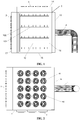
FIG. 1 shows a front view of the cache device according to an embodiment of the present invention; - 25.
FIG. 2 shows a bottom view of the cache device according to the embodiment of the present invention; - 26.
FIG. 3 shows a perspective view of the cache device in a first direction according to the embodiment of the present invention; and - 27.
FIG. 4 shows a perspective view of the cache device in a second direction according to the embodiment of the present invention. - 28. Referring to
FIGs. 1 -4 , the structure of a cache device provided by an embodiment of the present invention is shown. The cache device is used for, e.g., supporting glass substrates. As shown in the figures, the cache device includes an outer frame, the structure which is substantially embodied as non-closed box, as can be found in related arts. A first side wall of the outer frame, such as the front side wall, has anopening 10 for picking and placing the cached items. A second side wall of the outer frame opposite to the first side wall, such as theback wall 11, athird side wall 12 and a forth side wall which are opposed to each other, for example, theleft side wall 12 and theright side wall 13, a fifth side wall and a sixth side wall which are opposed to each other, such as thetop wall 14 and thebottom wall 15, are preferably detachably provided with a cover plate to define a relatively isolated space for protecting glass substrates. - 29. A support bracket for horizontally supporting cached items (such as glass substrates) is arranged inside of the outer frame. Preferably, the support bracket comprises a plurality of levels of horizontal cross beams 100, on each level of which a plurality of vertical support pins 101 are densely arranged. The cached glass substrates can be horizontally supported on the support pins. The horizontal cross beams and the support pins thereon may be made of aluminum. The position where support pins are in contact with glass substrates may also be sheathed with a protective sleeve made of Peek (polyetheretherketone resin) to prevent glass substrates from being scratched by support pins. The body and the side walls of the outer frame may be made of stainless steel. The cache device is also supported by a supporting seat (not shown) on the bottom side, so that the cache device is at a height that allows the operator to pick and place glass substrates conveniently.
- 30. The cache device provided in this embodiment further includes first blowing means 2, second air blowing means 3, and an
exhaust duct 4. The first blowing means 2 is disposed on theback wall 11 of the outer frame, intended to blows air toward theopening 10, that is, the first blowing means 2 substantially blows air horizontally from theback wall 11 toward theopening 10. It can be understood that the air stream blown by the first blowing means 2 is a filtered clean air stream. Preferably, the first blowing means 2 may be a plurality of Equipment Fan-filters Units (hereinafter referred to as EFU) mounted on the back wall of the outer frame and arranged in a rectangular array, and the air stream blown by the EFUs runs through the interior of the outer frame substantially in a horizontal direction and then is discharged from theopening 10. Compared with the clean means in the related art in which EFUs are installed on the top wall to blow air downwards (when the cache device is not idle, carried dust particles cannot be blown away once fall on the glass substrates because the flow direction of the clean air stream is orthogonal to the glass substrate, and it is necessary to shut down the EFUs), basic cleaning of the cache device for 24 hours a day can be achieved without stopping the EFUs and being limited to the idle time of the cache device only, even when glass substrates are placed inside the cache device of this embodiment, because the blowing direction of the first blowing means 2 is substantially parallel to the plane for placing the glass substrates, thus improving daily cleaning effect. In addition, the air stream discharged from the opening does not exert negative affect on other products on both sides of the cache device in the (upstream and downstream) production line since the first blowing means 2 blows air toward theopening 10. - 31. The second blowing means 3 is disposed on the
left side wall 12 of the outer frame for blowing clean air into the outer frame. It can be understood that the air stream blown by the second blowing means 3 should also be filtered clean air. Theexhaust duct 4 is disposed on theright side wall 13 of the outer frame and is adapted to communicate with the exhaust means for exhausting gas inside the outer frame and mainly for exhausting clean gas blown by the second blowing means 3. Preferably, the blowing means may be a vacuum blowing device. - 32. The second blowing means 3 may also employ EFUs to horizontally blow air from left to right. Or alternatively, the second blowing means 3 includes a plurality of nozzles adapted to communicate with a source of compressed dry air, and the plurality of nozzles arranged in a rectangular array on the left side wall. The source of compressed dry air preferably provides compressed dry air at 0.5 Mpa to 0.6 Mpa, so that the pressure of the air stream blown by the second blowing meaning 3 is not less than the pressure of the air stream blown by the first blowing means 2 to be more capable of cleaning. In this way, the direction of the air stream blown by the second air blowing means 3 is not parallel to the direction of the air stream blown by the first air blowing means 2, so that areas where the first blowing means 2 cannot blown can be cleaned additionally to realize deep cleaning. When the second blowing means 3 blows air, the air stream from the left side can be discharged by the exhaust means without providing vents on the
right side wall 13 for air communication, which also avoids adverse effect on the product on the right side of the cache device in the product line caused by provision of vents communicating with the environment on the right side wall. It can be understood that in other embodiments, the positions of the second blowing means 3 and theexhaust duct 4 are interchangeable, which means that the second blowing means 3 may be disposed on the right side wall of the outer frame, and theexhaust duct 4 may be disposed on the left side wall thereof. - 33. Preferably, each nozzle of the second blowing means 3 may be a 360 ° rotating nozzle to cover more cleaning angles and a larger cleaning range, and to further reduce blind areas. When each nozzle is a 360 ° rotating nozzle, in order to prevent clean air stream at high pressure from striking cached glass substrates when being blown obliquely upward or downward, the second blowing means 3 and the exhaust means can be activated when the cache device is idle in the normal working state.
- 34. Preferably, in order to allow the clean stream blown by the second blowing means 3 to be exhausted by the air exhaust means more easily, a
vertical guide plate 16 may also be disposed inside theright side wall 13 on which theexhaust duct 4 is provided. Thevertical guide plate 16 is arranged in parallel with theright side wall 13 and provided with a plurality of guide holes 160, so that the clean air blown by the second blowing means 3 may be exhausted by the exhaust means after being guided relatively uniformly into theexhaust duct 4, which facilitates uniform flow of clean air stream inside the cache device. Of course, in other embodiments, if theexhaust duct 4 is mounted on theleft side wall 12, the vertical guide plate is disposed approximate to the inner side of theleft side wall 12 and in parallel with theleft side wall 12. - 35. In order to further enhance the cleaning effect, the cache device further comprises third blowing means 5 arranged on the
top wall 14 of the outer frame for blowing clean air to the interior of the outer frame. It can be understood that the air stream blown by the third blowing means 3 may also be filtered clean air. In order to exhaust the clean air blown by the third blowing means 5 smoothly, on thebottom wall 15 of the outer frame a plurality ofvents 150 are provided, which may have a larger inner diameter, and through which clean air flows to the lower part of the cache device, without affecting the product located on both sides of the cache device in the production line. - 36. The third blowing means 5 may also be embodied as EFUs for blowing air from top to bottom. Or alternatively, the third blowing means 5 includes a plurality of nozzles adapted to be in communication with a source of compressed dry air and arranged in a rectangular array on the
top wall 14. The third blowing means 5 may share the source of compressed dry air source with the second blowing means 3, or the pressure of the air stream blown by the third blowing means 5may be not less than the pressure of the air steam blown by the second blowing means 3, for instance, the pressure of compressed dry air communicated with the third blowing means 5 ranging from 0.7Mpa to 0.8Mpa. In this way, the direction of the air stream blown by the third blowing means 5 is different from the direction of the air stream blown by the first air blowing means 2 and the second blowing means 3, so that the interior of the cache device can be cleaned more thoroughly. - 37. Preferably, each nozzle of the third blowing means 5 may also be a 360 ° rotating nozzle. In addition, in order to achieve a balance between the cleaning effect and resource saving, the third blowing means 5 can be activated only on PM days.
- 38. In order to realize the automatic control of the cleaning operation of the cache device, preferably, the cache device further comprises detecting means and a controller. The detecting means may for example comprise a approach switch provided inside the cache device for detecting the storage state in the cache device. In the normal operation state of the cache device, the first blowing means 2 keeps running. When the idle time of the cache device exceeds a determined period of time (for example, 30 minutes), the detecting means sends a start signal to the controller, which in turn controls the second blowing means 3 and the exhaust means to start according to the start signal, so that the second blowing means 3 and the exhaust means are stopped after running for a predetermined period of time (for example, 30 minutes), realizing automatic start and stop of the second blowing means 3 and the exhaust means. Preferably, the controller may be a PLC controller.
- 39. In addition, when the second blowing means 3 and the exhaust means are in operation, the detection means sends a stop signal to the controller when detecting any cached item stored in the cache device. The controller controls the second blowing means and the exhaust means to stop according to the
stop signal 3, preventing strong air stream blown by the second blowing means 3 from impacting the glass substrates. - 40. Preferably, the cache device further comprises an input unit, which may also be connected with the controller, which controls the start and the stop of the third blowing means 5 according to the information input from the input unit that may be a touch screen. If PM day of the cache device is a fixed day, the automatic mode can be selected on the touch screen. According to the data pre-input in the program, the third blowing means 5 can start automatically on set PM day and stop automatically s after running for a certain period of time. If the PM day is not fixed, manual mode can be selected by clicking the start /stop button on the touch screen manually to realize a start / stop function of the third blowing means, or by clicking the start button in manual mode and stopping the third blowing means automatically after e.g., 4 hours.
- 41. To sum up, the cache device provided in this embodiment can provide two cleaning modes: a normal cleaning mode suitable for normal cleaning on normal production days, where the first blowing means 2 keeps running continuously and the second blowing means 3, and the exhaust means operate according to the storage state of the cache device; and a PM cleaning mode suitable for thorough cleaning on PM days, where the first blowing means 2, the second blowing means 3, the exhaust means, and the third blowing means 5 are all activated for a predetermined period of time.
- Test shows that when the normal clean mode is performed on the normal production day of the cache device, the proportion of dust and particles removed is about 80%, whereas when cleaning is performed on PM days, the proportion of dust and particles removed is approximately 100%. However, current cache devices have a dust removal ratio of about 50% on the production day and about 70% on PM days. Therefore, the cache device provided in this embodiment not only reduces the difficulty in cleaning the interior space, but also improves the cleaning efficiency and cleaning effect.
- 42. An embodiment of the present invention further provides an LCD screen production line which is equipped with the cache device in the embodiment of the present invention, and therefore, which can produce the technical effect created by the cache device as illustrated above.
- 43. It may be understood that the above embodiments of the present disclosure are merely exemplary embodiments used for illustrating the principle of the present disclosure, but the disclosure is not limited thereto. For those skilled in the art, various modifications and improvements may be made without departing from the spirit and essence of the present disclosure, and are also deemed to be within the protection scope of the present disclosure. The scope of the present disclosure is defined only by the meaning of the language expressions of the appended claims and their equivalents.
Claims (10)
- A cache device, comprising:a frame, a first side wall of which has an opening for picking and placing cached items;a support bracket located in an area surrounded by the frame for supporting cached items;first blowing means on a second side wall opposite to the first side wall of the frame; the first blowing means being configured to blow air toward the opening;second blowing means on a third side wall of the frame adjacent to the first side wall; andexhaust means disposed on a fourth side wall opposite to the third side wall of the frame.
- The cache device according to claim 1, further comprising: third air blowing means provided on a fifth side wall of the frame; at least one vent provided on a sixth side wall opposed to the fifth side wall.
- The cache device according to claim 2, wherein the second blowing means is configured that the pressure of the air steam blown is not less than the pressure of the air stream blown by the first blowing means, and/or the third blowing means is configured that the pressure of the air stream blown is not less than the pressure of the air stream blown by the second blowing means.
- The cache device according to claim 2, wherein the fourth side wall comprises a vertical guide plate, on which at least one guide hole is arranged.
- The cache device according to claim 2, wherein,
the first blowing means includes a plurality of EFUs arranged in a rectangular array; and/or,
the second blowing means and the third blowing means each include a plurality of nozzles adapted to be in communication with a source of compressed dry air; and/or,
the exhaust means is a vacuum exhaust means. - The cache device according to claim 5, wherein the nozzle is a 360 ° rotating nozzle.
- The cache device according to any of claims 2 to 6, further comprising detecting means and a controller, wherein the detecting means is configured to detect a storage state in the cache device; and the first blowing means keeps operating when the cache device is in normal working state; the detecting means sends a start signal to the controller when the idle time of the cache device exceeds a predetermined period of time; and the controller controls the second blowing means and the exhaust means to start according to the start signal, allowing the second blowing means and the exhaust means to operate for a predetermined period of time .
- The cache device according to claim 7, wherein during the operation of the second blowing means and the exhaust means, the detecting means, when detecting that a cache item is stored in the cache device, sends a stop signal to the controller, which in turn controls the second blowing means and the exhaust means to stop according to the stop signal.
- The cache device according to claim 7, further comprising: an input unit which is in signal connection with the controller, which controls the start and stop of the third blowing means according to the information input from the input unit.
- A liquid crystal display screen production line equipped with the cache device according to any one of claims 1 to 9.
Applications Claiming Priority (2)
| Application Number | Priority Date | Filing Date | Title |
|---|---|---|---|
| CN201710093304.0A CN108459423B (en) | 2017-02-21 | 2017-02-21 | Cache device and LCD screen production line |
| PCT/CN2017/098817 WO2018153041A1 (en) | 2017-02-21 | 2017-08-24 | Cache device and liquid crystal screen production line |
Publications (3)
| Publication Number | Publication Date |
|---|---|
| EP3591459A1 true EP3591459A1 (en) | 2020-01-08 |
| EP3591459A4 EP3591459A4 (en) | 2021-06-16 |
| EP3591459B1 EP3591459B1 (en) | 2022-01-19 |
Family
ID=63228860
Family Applications (1)
| Application Number | Title | Priority Date | Filing Date |
|---|---|---|---|
| EP17847783.2A Active EP3591459B1 (en) | 2017-02-21 | 2017-08-24 | Cache device and liquid crystal screen production line |
Country Status (4)
| Country | Link |
|---|---|
| US (1) | US10625311B2 (en) |
| EP (1) | EP3591459B1 (en) |
| CN (1) | CN108459423B (en) |
| WO (1) | WO2018153041A1 (en) |
Families Citing this family (5)
| Publication number | Priority date | Publication date | Assignee | Title |
|---|---|---|---|---|
| CN110307609A (en) * | 2019-07-12 | 2019-10-08 | 世源科技工程有限公司 | A kind of toilet's storage |
| CN111599894B (en) * | 2020-05-29 | 2022-03-08 | 苏州拓升智能装备有限公司 | Double-graphite-boat cache cooling device suitable for TOPCon battery |
| CN112495935B (en) * | 2020-12-22 | 2023-08-15 | 合肥皖液液压元件有限公司 | Accurate grinding truss for automatic transportation of gear pump |
| CN114833138A (en) * | 2022-04-07 | 2022-08-02 | 安徽霖源光电科技有限公司 | Lens surface cleaning equipment |
| CN116765043A (en) * | 2023-07-17 | 2023-09-19 | 中国科学院上海高等研究院 | Automatic blowing device of fitting for super-clean assembly of superconducting cavity |
Family Cites Families (11)
| Publication number | Priority date | Publication date | Assignee | Title |
|---|---|---|---|---|
| US5303482A (en) * | 1991-01-29 | 1994-04-19 | Shinko Electric Co., Ltd. | Wafer airtight keeping unit and keeping facility thereof |
| JP2002299427A (en) * | 2001-03-29 | 2002-10-11 | Mitsubishi Electric Corp | Substrate cassette, substrate contamination prevention device, and method of manufacturing semiconductor device |
| JP2004055814A (en) * | 2002-07-19 | 2004-02-19 | Hirata Corp | Substrate processing equipment |
| CN2923597Y (en) * | 2006-05-09 | 2007-07-18 | 财团法人工业技术研究院 | Automated clean storage |
| JP4807579B2 (en) * | 2006-09-13 | 2011-11-02 | 株式会社ダイフク | Substrate storage equipment and substrate processing equipment |
| US7758338B2 (en) * | 2007-05-29 | 2010-07-20 | Taiwan Semiconductor Manufacturing Co., Ltd. | Substrate carrier, port apparatus and facility interface and apparatus including same |
| CN101844661B (en) * | 2010-05-31 | 2012-05-23 | 友达光电股份有限公司 | Clean warehouse |
| JP2012089645A (en) * | 2010-10-19 | 2012-05-10 | Muratec Automation Co Ltd | Article conveyance vehicle |
| JP5528308B2 (en) * | 2010-11-22 | 2014-06-25 | 信越ポリマー株式会社 | Substrate storage container |
| CN104867853A (en) * | 2015-03-30 | 2015-08-26 | 上海华力微电子有限公司 | FOUP structure and FOUP cleaning method |
| KR102066175B1 (en) * | 2017-12-28 | 2020-01-14 | 우범제 | Wafer storage container |
-
2017
- 2017-02-21 CN CN201710093304.0A patent/CN108459423B/en active Active
- 2017-08-24 WO PCT/CN2017/098817 patent/WO2018153041A1/en not_active Ceased
- 2017-08-24 EP EP17847783.2A patent/EP3591459B1/en active Active
- 2017-08-24 US US15/761,006 patent/US10625311B2/en active Active
Also Published As
| Publication number | Publication date |
|---|---|
| US20190030575A1 (en) | 2019-01-31 |
| CN108459423B (en) | 2020-05-12 |
| EP3591459A4 (en) | 2021-06-16 |
| WO2018153041A1 (en) | 2018-08-30 |
| US10625311B2 (en) | 2020-04-21 |
| EP3591459B1 (en) | 2022-01-19 |
| CN108459423A (en) | 2018-08-28 |
Similar Documents
| Publication | Publication Date | Title |
|---|---|---|
| US10625311B2 (en) | Cache device and LCD screen production line | |
| KR101703032B1 (en) | Glass panel overhead system | |
| KR100524359B1 (en) | Storage facility for use in a clean-room | |
| US20160059276A1 (en) | Dedusting and destaticizing device | |
| US20100320786A1 (en) | Noncontact type suction gripping device and noncontact type suction gripping frame having the same | |
| KR101218400B1 (en) | Vacuum sticking apparatus | |
| CN105744710A (en) | Dust-removing electrostatic-eliminating equipment | |
| JP4494269B2 (en) | Substrate processing equipment | |
| KR20100059457A (en) | Single Sheet Substrate Processing Equipment | |
| KR101574436B1 (en) | Device for chamber residual gas exhaust hood | |
| CN106077011B (en) | A kind of exhausting cloth wind adjustment type chemical experiment draught cupboard | |
| KR100549948B1 (en) | Clean System of Semiconductor Manufacturing Equipment | |
| CN203545883U (en) | Novel transparent conductive film glass thinning bearing device | |
| KR100885907B1 (en) | Air Cleaning Unit for Air Clean Room | |
| KR100815521B1 (en) | Substrate Drying Equipment | |
| KR20150029276A (en) | A laminating system | |
| KR101661139B1 (en) | Residual gas exhaust hood Device for chamber | |
| CN204332921U (en) | Cleaning equipment or wet processing equipment for silicon wafers | |
| CN220902172U (en) | Laser boron doping equipment with efficient dust removal system | |
| CN213386232U (en) | Part conveying device for machining of automobile instrument panel | |
| KR101993686B1 (en) | Chamber changeable wafer automatic care system | |
| JP2015027638A (en) | Cleaning apparatus and cleaning method for box-shaped body | |
| TWI818729B (en) | Decontamination apparatus for low-level radioactive contamination object and operation method thereof | |
| KR101916784B1 (en) | Clean air blower unit | |
| CN208991947U (en) | Cutting machine is used in a kind of production of steel construction |
Legal Events
| Date | Code | Title | Description |
|---|---|---|---|
| STAA | Information on the status of an ep patent application or granted ep patent |
Free format text: STATUS: UNKNOWN |
|
| STAA | Information on the status of an ep patent application or granted ep patent |
Free format text: STATUS: THE INTERNATIONAL PUBLICATION HAS BEEN MADE |
|
| PUAI | Public reference made under article 153(3) epc to a published international application that has entered the european phase |
Free format text: ORIGINAL CODE: 0009012 |
|
| STAA | Information on the status of an ep patent application or granted ep patent |
Free format text: STATUS: REQUEST FOR EXAMINATION WAS MADE |
|
| 17P | Request for examination filed |
Effective date: 20180316 |
|
| AK | Designated contracting states |
Kind code of ref document: A1 Designated state(s): AL AT BE BG CH CY CZ DE DK EE ES FI FR GB GR HR HU IE IS IT LI LT LU LV MC MK MT NL NO PL PT RO RS SE SI SK SM TR |
|
| AX | Request for extension of the european patent |
Extension state: BA ME |
|
| DAV | Request for validation of the european patent (deleted) | ||
| DAX | Request for extension of the european patent (deleted) | ||
| REG | Reference to a national code |
Ref country code: DE Ref legal event code: R079 Ref document number: 602017052582 Country of ref document: DE Free format text: PREVIOUS MAIN CLASS: G02F0001130000 Ipc: H01L0021673000 |
|
| A4 | Supplementary search report drawn up and despatched |
Effective date: 20210518 |
|
| RIC1 | Information provided on ipc code assigned before grant |
Ipc: B08B 5/02 20060101ALI20210511BHEP Ipc: H01L 21/677 20060101ALI20210511BHEP Ipc: H01L 21/673 20060101AFI20210511BHEP |
|
| GRAP | Despatch of communication of intention to grant a patent |
Free format text: ORIGINAL CODE: EPIDOSNIGR1 |
|
| STAA | Information on the status of an ep patent application or granted ep patent |
Free format text: STATUS: GRANT OF PATENT IS INTENDED |
|
| INTG | Intention to grant announced |
Effective date: 20210927 |
|
| GRAS | Grant fee paid |
Free format text: ORIGINAL CODE: EPIDOSNIGR3 |
|
| GRAA | (expected) grant |
Free format text: ORIGINAL CODE: 0009210 |
|
| STAA | Information on the status of an ep patent application or granted ep patent |
Free format text: STATUS: THE PATENT HAS BEEN GRANTED |
|
| AK | Designated contracting states |
Kind code of ref document: B1 Designated state(s): AL AT BE BG CH CY CZ DE DK EE ES FI FR GB GR HR HU IE IS IT LI LT LU LV MC MK MT NL NO PL PT RO RS SE SI SK SM TR |
|
| REG | Reference to a national code |
Ref country code: GB Ref legal event code: FG4D |
|
| REG | Reference to a national code |
Ref country code: CH Ref legal event code: EP |
|
| REG | Reference to a national code |
Ref country code: DE Ref legal event code: R096 Ref document number: 602017052582 Country of ref document: DE |
|
| REG | Reference to a national code |
Ref country code: AT Ref legal event code: REF Ref document number: 1464285 Country of ref document: AT Kind code of ref document: T Effective date: 20220215 |
|
| REG | Reference to a national code |
Ref country code: IE Ref legal event code: FG4D |
|
| REG | Reference to a national code |
Ref country code: LT Ref legal event code: MG9D |
|
| REG | Reference to a national code |
Ref country code: NL Ref legal event code: MP Effective date: 20220119 |
|
| REG | Reference to a national code |
Ref country code: AT Ref legal event code: MK05 Ref document number: 1464285 Country of ref document: AT Kind code of ref document: T Effective date: 20220119 |
|
| PG25 | Lapsed in a contracting state [announced via postgrant information from national office to epo] |
Ref country code: NL Free format text: LAPSE BECAUSE OF FAILURE TO SUBMIT A TRANSLATION OF THE DESCRIPTION OR TO PAY THE FEE WITHIN THE PRESCRIBED TIME-LIMIT Effective date: 20220119 |
|
| PG25 | Lapsed in a contracting state [announced via postgrant information from national office to epo] |
Ref country code: SE Free format text: LAPSE BECAUSE OF FAILURE TO SUBMIT A TRANSLATION OF THE DESCRIPTION OR TO PAY THE FEE WITHIN THE PRESCRIBED TIME-LIMIT Effective date: 20220119 Ref country code: RS Free format text: LAPSE BECAUSE OF FAILURE TO SUBMIT A TRANSLATION OF THE DESCRIPTION OR TO PAY THE FEE WITHIN THE PRESCRIBED TIME-LIMIT Effective date: 20220119 Ref country code: PT Free format text: LAPSE BECAUSE OF FAILURE TO SUBMIT A TRANSLATION OF THE DESCRIPTION OR TO PAY THE FEE WITHIN THE PRESCRIBED TIME-LIMIT Effective date: 20220519 Ref country code: NO Free format text: LAPSE BECAUSE OF FAILURE TO SUBMIT A TRANSLATION OF THE DESCRIPTION OR TO PAY THE FEE WITHIN THE PRESCRIBED TIME-LIMIT Effective date: 20220419 Ref country code: LT Free format text: LAPSE BECAUSE OF FAILURE TO SUBMIT A TRANSLATION OF THE DESCRIPTION OR TO PAY THE FEE WITHIN THE PRESCRIBED TIME-LIMIT Effective date: 20220119 Ref country code: HR Free format text: LAPSE BECAUSE OF FAILURE TO SUBMIT A TRANSLATION OF THE DESCRIPTION OR TO PAY THE FEE WITHIN THE PRESCRIBED TIME-LIMIT Effective date: 20220119 Ref country code: ES Free format text: LAPSE BECAUSE OF FAILURE TO SUBMIT A TRANSLATION OF THE DESCRIPTION OR TO PAY THE FEE WITHIN THE PRESCRIBED TIME-LIMIT Effective date: 20220119 Ref country code: BG Free format text: LAPSE BECAUSE OF FAILURE TO SUBMIT A TRANSLATION OF THE DESCRIPTION OR TO PAY THE FEE WITHIN THE PRESCRIBED TIME-LIMIT Effective date: 20220419 |
|
| PG25 | Lapsed in a contracting state [announced via postgrant information from national office to epo] |
Ref country code: PL Free format text: LAPSE BECAUSE OF FAILURE TO SUBMIT A TRANSLATION OF THE DESCRIPTION OR TO PAY THE FEE WITHIN THE PRESCRIBED TIME-LIMIT Effective date: 20220119 Ref country code: LV Free format text: LAPSE BECAUSE OF FAILURE TO SUBMIT A TRANSLATION OF THE DESCRIPTION OR TO PAY THE FEE WITHIN THE PRESCRIBED TIME-LIMIT Effective date: 20220119 Ref country code: GR Free format text: LAPSE BECAUSE OF FAILURE TO SUBMIT A TRANSLATION OF THE DESCRIPTION OR TO PAY THE FEE WITHIN THE PRESCRIBED TIME-LIMIT Effective date: 20220420 Ref country code: FI Free format text: LAPSE BECAUSE OF FAILURE TO SUBMIT A TRANSLATION OF THE DESCRIPTION OR TO PAY THE FEE WITHIN THE PRESCRIBED TIME-LIMIT Effective date: 20220119 Ref country code: AT Free format text: LAPSE BECAUSE OF FAILURE TO SUBMIT A TRANSLATION OF THE DESCRIPTION OR TO PAY THE FEE WITHIN THE PRESCRIBED TIME-LIMIT Effective date: 20220119 |
|
| PG25 | Lapsed in a contracting state [announced via postgrant information from national office to epo] |
Ref country code: IS Free format text: LAPSE BECAUSE OF FAILURE TO SUBMIT A TRANSLATION OF THE DESCRIPTION OR TO PAY THE FEE WITHIN THE PRESCRIBED TIME-LIMIT Effective date: 20220519 |
|
| REG | Reference to a national code |
Ref country code: DE Ref legal event code: R097 Ref document number: 602017052582 Country of ref document: DE |
|
| PG25 | Lapsed in a contracting state [announced via postgrant information from national office to epo] |
Ref country code: SM Free format text: LAPSE BECAUSE OF FAILURE TO SUBMIT A TRANSLATION OF THE DESCRIPTION OR TO PAY THE FEE WITHIN THE PRESCRIBED TIME-LIMIT Effective date: 20220119 Ref country code: SK Free format text: LAPSE BECAUSE OF FAILURE TO SUBMIT A TRANSLATION OF THE DESCRIPTION OR TO PAY THE FEE WITHIN THE PRESCRIBED TIME-LIMIT Effective date: 20220119 Ref country code: RO Free format text: LAPSE BECAUSE OF FAILURE TO SUBMIT A TRANSLATION OF THE DESCRIPTION OR TO PAY THE FEE WITHIN THE PRESCRIBED TIME-LIMIT Effective date: 20220119 Ref country code: EE Free format text: LAPSE BECAUSE OF FAILURE TO SUBMIT A TRANSLATION OF THE DESCRIPTION OR TO PAY THE FEE WITHIN THE PRESCRIBED TIME-LIMIT Effective date: 20220119 Ref country code: DK Free format text: LAPSE BECAUSE OF FAILURE TO SUBMIT A TRANSLATION OF THE DESCRIPTION OR TO PAY THE FEE WITHIN THE PRESCRIBED TIME-LIMIT Effective date: 20220119 Ref country code: CZ Free format text: LAPSE BECAUSE OF FAILURE TO SUBMIT A TRANSLATION OF THE DESCRIPTION OR TO PAY THE FEE WITHIN THE PRESCRIBED TIME-LIMIT Effective date: 20220119 |
|
| PLBE | No opposition filed within time limit |
Free format text: ORIGINAL CODE: 0009261 |
|
| STAA | Information on the status of an ep patent application or granted ep patent |
Free format text: STATUS: NO OPPOSITION FILED WITHIN TIME LIMIT |
|
| PG25 | Lapsed in a contracting state [announced via postgrant information from national office to epo] |
Ref country code: AL Free format text: LAPSE BECAUSE OF FAILURE TO SUBMIT A TRANSLATION OF THE DESCRIPTION OR TO PAY THE FEE WITHIN THE PRESCRIBED TIME-LIMIT Effective date: 20220119 |
|
| 26N | No opposition filed |
Effective date: 20221020 |
|
| PG25 | Lapsed in a contracting state [announced via postgrant information from national office to epo] |
Ref country code: SI Free format text: LAPSE BECAUSE OF FAILURE TO SUBMIT A TRANSLATION OF THE DESCRIPTION OR TO PAY THE FEE WITHIN THE PRESCRIBED TIME-LIMIT Effective date: 20220119 |
|
| PG25 | Lapsed in a contracting state [announced via postgrant information from national office to epo] |
Ref country code: MC Free format text: LAPSE BECAUSE OF FAILURE TO SUBMIT A TRANSLATION OF THE DESCRIPTION OR TO PAY THE FEE WITHIN THE PRESCRIBED TIME-LIMIT Effective date: 20220119 |
|
| REG | Reference to a national code |
Ref country code: CH Ref legal event code: PL |
|
| GBPC | Gb: european patent ceased through non-payment of renewal fee |
Effective date: 20220824 |
|
| PG25 | Lapsed in a contracting state [announced via postgrant information from national office to epo] |
Ref country code: LU Free format text: LAPSE BECAUSE OF NON-PAYMENT OF DUE FEES Effective date: 20220824 Ref country code: LI Free format text: LAPSE BECAUSE OF NON-PAYMENT OF DUE FEES Effective date: 20220831 Ref country code: CH Free format text: LAPSE BECAUSE OF NON-PAYMENT OF DUE FEES Effective date: 20220831 |
|
| REG | Reference to a national code |
Ref country code: BE Ref legal event code: MM Effective date: 20220831 |
|
| PG25 | Lapsed in a contracting state [announced via postgrant information from national office to epo] |
Ref country code: IT Free format text: LAPSE BECAUSE OF FAILURE TO SUBMIT A TRANSLATION OF THE DESCRIPTION OR TO PAY THE FEE WITHIN THE PRESCRIBED TIME-LIMIT Effective date: 20220119 Ref country code: IE Free format text: LAPSE BECAUSE OF NON-PAYMENT OF DUE FEES Effective date: 20220824 Ref country code: FR Free format text: LAPSE BECAUSE OF NON-PAYMENT OF DUE FEES Effective date: 20220831 |
|
| PG25 | Lapsed in a contracting state [announced via postgrant information from national office to epo] |
Ref country code: BE Free format text: LAPSE BECAUSE OF NON-PAYMENT OF DUE FEES Effective date: 20220831 |
|
| PG25 | Lapsed in a contracting state [announced via postgrant information from national office to epo] |
Ref country code: GB Free format text: LAPSE BECAUSE OF NON-PAYMENT OF DUE FEES Effective date: 20220824 |
|
| PG25 | Lapsed in a contracting state [announced via postgrant information from national office to epo] |
Ref country code: HU Free format text: LAPSE BECAUSE OF FAILURE TO SUBMIT A TRANSLATION OF THE DESCRIPTION OR TO PAY THE FEE WITHIN THE PRESCRIBED TIME-LIMIT; INVALID AB INITIO Effective date: 20170824 |
|
| PG25 | Lapsed in a contracting state [announced via postgrant information from national office to epo] |
Ref country code: CY Free format text: LAPSE BECAUSE OF FAILURE TO SUBMIT A TRANSLATION OF THE DESCRIPTION OR TO PAY THE FEE WITHIN THE PRESCRIBED TIME-LIMIT Effective date: 20220119 |
|
| PG25 | Lapsed in a contracting state [announced via postgrant information from national office to epo] |
Ref country code: MK Free format text: LAPSE BECAUSE OF FAILURE TO SUBMIT A TRANSLATION OF THE DESCRIPTION OR TO PAY THE FEE WITHIN THE PRESCRIBED TIME-LIMIT Effective date: 20220119 |
|
| PG25 | Lapsed in a contracting state [announced via postgrant information from national office to epo] |
Ref country code: TR Free format text: LAPSE BECAUSE OF FAILURE TO SUBMIT A TRANSLATION OF THE DESCRIPTION OR TO PAY THE FEE WITHIN THE PRESCRIBED TIME-LIMIT Effective date: 20220119 |
|
| PG25 | Lapsed in a contracting state [announced via postgrant information from national office to epo] |
Ref country code: MT Free format text: LAPSE BECAUSE OF FAILURE TO SUBMIT A TRANSLATION OF THE DESCRIPTION OR TO PAY THE FEE WITHIN THE PRESCRIBED TIME-LIMIT Effective date: 20220119 |
|
| PGFP | Annual fee paid to national office [announced via postgrant information from national office to epo] |
Ref country code: DE Payment date: 20250820 Year of fee payment: 9 |
|
| REG | Reference to a national code |
Ref country code: DE Ref legal event code: R079 Ref document number: 602017052582 Country of ref document: DE Free format text: PREVIOUS MAIN CLASS: H01L0021673000 Ipc: H10P0072100000 |