EP3591367A1 - Système ou procédé de détermination de l'état d'un roulement - Google Patents
Système ou procédé de détermination de l'état d'un roulement Download PDFInfo
- Publication number
- EP3591367A1 EP3591367A1 EP19000377.2A EP19000377A EP3591367A1 EP 3591367 A1 EP3591367 A1 EP 3591367A1 EP 19000377 A EP19000377 A EP 19000377A EP 3591367 A1 EP3591367 A1 EP 3591367A1
- Authority
- EP
- European Patent Office
- Prior art keywords
- bearing
- unit
- value
- values
- simulation
- Prior art date
- Legal status (The legal status is an assumption and is not a legal conclusion. Google has not performed a legal analysis and makes no representation as to the accuracy of the status listed.)
- Granted
Links
- 238000000034 method Methods 0.000 title claims abstract description 38
- 238000004088 simulation Methods 0.000 claims abstract description 51
- 230000001419 dependent effect Effects 0.000 claims abstract description 5
- 238000011156 evaluation Methods 0.000 claims description 37
- 238000005461 lubrication Methods 0.000 claims description 14
- 230000008569 process Effects 0.000 claims description 12
- 238000012545 processing Methods 0.000 claims description 8
- 230000008859 change Effects 0.000 claims description 7
- 239000004519 grease Substances 0.000 claims description 5
- 230000001050 lubricating effect Effects 0.000 description 10
- 238000005259 measurement Methods 0.000 description 10
- 235000015095 lager Nutrition 0.000 description 7
- 239000000463 material Substances 0.000 description 7
- 238000009434 installation Methods 0.000 description 6
- 238000012544 monitoring process Methods 0.000 description 5
- 238000004364 calculation method Methods 0.000 description 4
- 238000005516 engineering process Methods 0.000 description 4
- 238000003860 storage Methods 0.000 description 4
- 238000009413 insulation Methods 0.000 description 3
- 238000012423 maintenance Methods 0.000 description 3
- 238000004904 shortening Methods 0.000 description 3
- 238000012360 testing method Methods 0.000 description 3
- 230000015572 biosynthetic process Effects 0.000 description 2
- 238000010891 electric arc Methods 0.000 description 2
- 230000008020 evaporation Effects 0.000 description 2
- 238000001704 evaporation Methods 0.000 description 2
- 230000010354 integration Effects 0.000 description 2
- 239000000314 lubricant Substances 0.000 description 2
- 230000008018 melting Effects 0.000 description 2
- 238000002844 melting Methods 0.000 description 2
- 230000003071 parasitic effect Effects 0.000 description 2
- 230000002028 premature Effects 0.000 description 2
- 230000000246 remedial effect Effects 0.000 description 2
- 230000005540 biological transmission Effects 0.000 description 1
- 238000006243 chemical reaction Methods 0.000 description 1
- 238000013461 design Methods 0.000 description 1
- 238000001514 detection method Methods 0.000 description 1
- 238000010586 diagram Methods 0.000 description 1
- 238000009826 distribution Methods 0.000 description 1
- 230000000694 effects Effects 0.000 description 1
- 238000007786 electrostatic charging Methods 0.000 description 1
- 230000008030 elimination Effects 0.000 description 1
- 238000003379 elimination reaction Methods 0.000 description 1
- 230000007613 environmental effect Effects 0.000 description 1
- 230000005284 excitation Effects 0.000 description 1
- 230000004907 flux Effects 0.000 description 1
- 230000017525 heat dissipation Effects 0.000 description 1
- 238000003754 machining Methods 0.000 description 1
- 238000007726 management method Methods 0.000 description 1
- 238000004519 manufacturing process Methods 0.000 description 1
- 239000002184 metal Substances 0.000 description 1
- 238000012986 modification Methods 0.000 description 1
- 230000004048 modification Effects 0.000 description 1
- 230000008439 repair process Effects 0.000 description 1
- 230000004044 response Effects 0.000 description 1
- 238000005096 rolling process Methods 0.000 description 1
- 239000007921 spray Substances 0.000 description 1
- 238000000859 sublimation Methods 0.000 description 1
- 230000008022 sublimation Effects 0.000 description 1
- 230000002123 temporal effect Effects 0.000 description 1
- 238000012546 transfer Methods 0.000 description 1
- 230000000007 visual effect Effects 0.000 description 1
- 238000004804 winding Methods 0.000 description 1
Images

Classifications
-
- G—PHYSICS
- G01—MEASURING; TESTING
- G01M—TESTING STATIC OR DYNAMIC BALANCE OF MACHINES OR STRUCTURES; TESTING OF STRUCTURES OR APPARATUS, NOT OTHERWISE PROVIDED FOR
- G01M13/00—Testing of machine parts
- G01M13/04—Bearings
Definitions
- the invention relates to a method and a device / system for simulating an electrical bearing load on a bearing of an electrical machine.
- EDM Electro Discharge Machining
- An object of the present invention is to provide a method and a device for simulating a bearing current or an electrical bearing load.
- the object is solved, for example, according to a method or system according to one of claims 1 to 15.
- Remedy is e.g. achieved by interrupting the current flow. Isolating a bearing, conveniently on the operator side, can solve the problem.
- bearing currents also occur due to converter supply.
- the basis is e.g. Power converter with voltage intermediate circuit.
- Parasitic effects occur in converter-fed motors, which can manifest themselves in the current flow through the motor bearing.
- Arc discharges over the lubricating film of the bearing can lead to material melting in the bearing raceways. In extreme cases, these changes can lead to a total failure of the storage.
- grounding brushes can be used between the rotor and the housing in three-phase drives with power electronic power supply. This achieves a grounding of the runner.
- earthing brushes are subject to wear, so that the maintenance and repair work increases.
- the contact safety of the grounding brushes is not always guaranteed, especially in difficult environmental conditions, so that bearing currents can build up and bearing wear can increase.
- other different remedial measures are possible, such as to avoid or minimize bearing damage, remedies in the hardware (other cables, better grounding, equipotential bonding in the system, grounding brushes, common mode filter).
- an electrical voltage applied to the electrical machine can be measured, a common-mode voltage being determined from the result of the voltage measurement, a compensation voltage being determined on the basis of the common-mode voltage, and a component of the electrical machine that is electrically connected to the bearing with the Compensation voltage is applied, so that a bearing voltage dropping across the bearing is at least partially compensated.
- the bearing currents can thus be suppressed in a manner specific to the operating point and the system, in particular in a condition-oriented manner.
- Applying the compensation voltage, determined in particular on the basis of a condition detection, to the bearing leads to extensive compensation of the bearing voltages, which would otherwise cause the arc discharges and thus the bearing currents if the values were too large.
- the remaining residual stresses in the bearings are too low to cause arcing to a damaging extent. In the ideal case, the measured bearing stresses even completely disappear due to the compensation.
- the bearing current and the bearing voltage are direct measurement variables that enable direct monitoring of the conditions in the respective bearing.
- the acquisition and in particular feedback of these direct measured variables allow a very quick reaction to changes in the condition of the warehouse.
- the measured value is, for example, an analog measured value or a digital measured value of a current or a voltage.
- the measured value or a large number of measured values is transmitted to a simulation unit.
- the simulation unit can e.g. the converter (for calculated values), or a sensor management unit (e.g. a condition monitoring system SIPLUS CMS), a processor located on a motor, etc.
- a result value can be determined using the simulation unit.
- the result value is, for example, a bearing current value or a value dependent on the bearing current.
- the result value can be transmitted to another unit.
- the result value is also, for example, a graphic representation, an alarm message, a warning message and / or a traffic light-like representation of the above-mentioned values such as bearing lubrication gap size, bearing capacity, bearing current, frequency of bearing current peaks, frequency of voltage peaks, etc.
- the further unit is, for example, an evaluation unit, with the evaluation unit processing the result value in such a way that a bearing condition value is determined.
- the evaluation unit can be a hardware unit, for example and / or a software unit.
- the simulation unit can also be a hardware unit and / or a software unit.
- the simulation unit and the evaluation unit can be implemented, for example, in the same hardware unit, so that the simulation and the evaluation run, for example, on the same processor unit.
- the result values and / or bearing condition values can be calculated on an integrated process computer.
- the integrated process computer has a simulation model by means of which the sizes are calculated.
- the integrated process computer is, for example, a programmable logic controller (PLC), a computer numerical control (CNC), an adjustable power converter or the like.
- PLC programmable logic controller
- CNC computer numerical control
- a combination of sensor and evaluation / simulation unit in a condition monitoring system can also be carried out.
- the evaluation unit or the simulation unit has, for example, a screen display, a result value in particular being shown on the screen display. Outputs in the form of a graphic or a value by means of a printer, an acoustic and / or visual message, a traffic light or the like are also possible. A bearing condition value can also be displayed. In one embodiment of the screen display, it has a pointer (digital or mechanical), by means of which a value can be displayed. If the displayed value exceeds a threshold value, a warning can be displayed in one embodiment of the display.
- the measured values are processed in real time in the simulation unit and / or in the evaluation unit.
- Result values and / or bearing condition values can be displayed to a person, that is to say an operator, in real time.
- Real time means processing or presentation promptly.
- a time offset due to, for example, computing times or data transmission times can occur.
- Such a system for determining a bearing state of a bearing of an electrical machine has, for example, a simulation unit, a sensor unit and / or an evaluation unit, the simulation unit being provided for processing data from the sensor unit and the evaluation unit being provided for processing data from the simulation unit ,
- the simulation unit has a model for simulating the bearing.
- the model can be used, for example, to calculate a crater-effective energy of the bearing to be considered.
- the simulation unit has a simulation model for calculating the bearing lubrication gap, bearing capacity and / or bearing current from the machine parameters and the external measured values.
- Machine parameters are e.g. the geometrical dimensions of the motor, grooves, insulation, lengths, useful numbers etc. From these, the stray capacities of the motor are calculated and the simulation model is formed.
- a capacitive equivalent circuit diagram of the motor can be used as part of the model.
- a precise description of the condition of the bearing or bearings by the simulation model can also provide information about the wear conditions of the motor bearings and / or the bearing grease. By estimating a remaining term, an end user can plan his maintenance intervals more precisely and thus prevent unplanned downtimes.
- the discharge time constant and energy of the discharge depend on the thickness of the lubricating film in the bearing. For example, a characteristic curve can be recorded beforehand as to which lubricating film thicknesses lead to which time constants and electrical capacities. Together with a BVR (Bearing Voltage Ratio) and the common-mode voltage of the converter, this can be used to infer the crater-effective energy. Parameters derived from the time constant and energy can also be used, e.g. Energy per unit volume at a certain voltage.
- a method for determining the film thickness using a loading time constant can also be used on a storage test rig.
- the lubricating film thicknesses are determined as a function of speed, bearing load and temperature. The result is a map that is integrated into the simulation model.
- the lubricating film thickness can now be concluded on the basis of the external measured values. 3D characteristics can be determined in advance on a test bench. It is also possible that in relation to the Test bench to transfer the procedure described to an online measurement.
- the energy of the spark discharge can be particularly harmful if the discharge takes place within a short period of time, so that the energy is sufficient to vaporize metal or even spray it as plasma before the energy is conducted by heat conduction at the speed of sound flows.
- Typical times in which the crater-effective energy is released before the energy has flowed away are in the range from 100 ps to 1 ns.
- Characteristic curves can, for example, be calculated analytically with respect to the time constants or numerically simulated and measured with respect to the discharge times depending on the lubricating film thickness. The characteristic curves then form a "bridge" between the mechanical parameter "lubricating film thickness” and the material removal by evaporation, which leads to the formation of corrugations.
- the combination of the electrical, thermodynamic and the mechanical model can therefore be used to estimate the effect of vibrations caused by normal operation or by pre-damage (notch caused by transport or assembly).
- Motor and system data for modeling can be fed to a measuring device (with sensor) using a simple input system.
- a computing unit this is, for example, the simulation unit and / or the evaluation unit
- a corresponding measuring unit in particular the measuring device
- relevant external data e.g. phase-to-earth voltage, shaft voltage, bearing sizes during operation.
- a combination with the bearing current sensor is also possible.
- an evaluation unit is supplied to each sensor unit.
- the simulation model which runs on a measuring device process computer, for example, can be based on a motor model, which e.g. runs on one of the common engine simulation platforms.
- a motor model which e.g. runs on one of the common engine simulation platforms.
- Such an electrical model can be used to describe the high-frequency behavior of motors.
- the HF models are supplemented by mechanical bearing models.
- Measurements determine vibrations, possibly also the temperature and other measured values such as the condition of the grease.
- the measured values flow into a mechanical model.
- the temperature can also be known, the temperature preferably being measured close to the bearing.
- the film thickness depends on the temperature. If no temperature is measured, this must be estimated or determined. An estimate can e.g. from the motor temperature (winding).
- the lubricant film thickness is determined using the mechanical model. This is advantageously done in the frequency domain or in the time domain, i.e. made dynamic.
- the use of a constant lubrication gap can be assumed.
- the crater-effective energy or a comparable parameter that corresponds to the temporal Heat flow (thermodynamic consideration) taken into account determined.
- an expected service life of the bearing can be determined.
- a comparison with the requirements shows whether changes are necessary. If necessary, these can then be evaluated in a new run of the scheme. Depending on the changes required, a complete run may be required or only a partial run is necessary.
- a mechanical change to the bearing and / or the electrical machine is carried out, after which a further determination of the bearing condition is carried out
- a system can be designed such that the model or models run on an integrated process computer.
- the process computer could, for example, be a programmable logic controller or a master computer.
- This technical data connection enables data such as voltage, current, pulse pattern, energy, active power, reactive power, DC link voltage, frequency to be transmitted to the respective unit in order to process this information there.
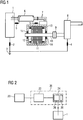
- FIG. 1 shows in principle a basic representation of a structure of a dynamoelectric machine with surrounding system parts.
- a converter 1 via connecting lines 7 connected to a dynamo-electric machine which is located within a motor housing 10 and has a stator 11 and a rotor 12 which drives a load machine 8 via bearings 14 and a shaft 13 via a clutch 9 or is driven by it.
- the electrical connection between the converter 1 and the dynamoelectric machine via the connection cable 7 has a cable shield 6, which has a corresponding connection 5 to the earth of the converter or motor housing. Both the converter 1 and the load machine 8 are connected to the ground 3 via a ground 2 or 4.
- the motor can also be connected to earth, but this is not shown in the figure.
- the engine can e.g. there are two grounding points.
- a grounding point loves, for example, in the area of a motor base.
- Another grounding point is, for example, in the area of a terminal box of the motor.
- the converter 1, in particular as a voltage intermediate circuit converter shows its output voltage by controlled switching of the DC voltage intermediate circuit on the output.
- a change of positive and negative potential in rapid succession leads to a voltage curve in a two-point inverter, the sum of which of the three-phase voltage is not equal to zero and results in the so-called common mode voltage.
- Each of these steep voltage switching actions causes high-frequency excitations with the resulting currents, which flow back to the source via parasitic paths.
- the sensor unit 20 is connected to the simulation unit 22 in terms of data technology.
- the simulation unit 22 is with the Evaluation unit 24 connected in terms of data technology.
- the power converter 1 is connected to the evaluation unit 24 in terms of data technology.
- the evaluation unit 24 has a screen display 26 (display). State values 31 can be transmitted from the converter 1 to the evaluation unit 24 and stored there.
- the functions of the simulation unit 22 and the evaluation unit 24 can be implemented with software and / or hardware.
- the simulation unit 22 and the evaluation unit are integrated in a process computer 36.
- the in FIG 2 The shown schematic structure of a system for evaluating a bearing shows that a real-time evaluation of a bearing condition can be achieved.
- the representation according to FIG 3 shows a method how inventory status data can be determined.
- a measured value 21 is determined by means of a sensor unit 20.
- the measured value 21 is transmitted to the simulation unit 22.
- the simulation unit 22 has a model 33.
- a result value 23 is determined by means of the model 33, which can also be a characteristic curve, and the measured value 21.
- the result value 23 is transmitted to the evaluation unit 24.
- the evaluation unit 24 has a screen display 26 which can be read by a person 29. Result values 25, 27 are used to determine at least one status value 31 of the bearing to be considered.
- measured values of measurement 40 in model 48 can be processed via a data path 41.
- Result values such as e.g. a crater-effective energy, which can be determined by means of a characteristic curve or by the model 48, into a model for material removal 52.
- Data on the bearing are imported into the model for material removal 52 via a data path 51. This results in a value with regard to a predicted bearing life.
- This value over the predicted bearing lifetime is transmitted via a data path 54 to a device 56 for evaluating an expected service life.
- This device 56 is loaded with data relating to the requirements regarding the service life of the bearing via a data path 55.
- the evaluation of the expected service life is too low, e.g. a design change is initiated, after which a measurement 40 is initiated again. This is indicated by path 57.
- this information can be output via a data path 58, for example graphically via a display 60.
Landscapes
- Physics & Mathematics (AREA)
- General Physics & Mathematics (AREA)
- Testing Of Devices, Machine Parts, Or Other Structures Thereof (AREA)
- Rolling Contact Bearings (AREA)
- Motor Or Generator Frames (AREA)
Applications Claiming Priority (3)
| Application Number | Priority Date | Filing Date | Title |
|---|---|---|---|
| DE102010002294A DE102010002294A1 (de) | 2010-02-24 | 2010-02-24 | System bzw. Verfahren zur Ermittlung eines Lagerzustandes |
| PCT/EP2011/051520 WO2011104091A1 (fr) | 2010-02-24 | 2011-02-03 | Système ou procédé de détermination de l'état d'un palier |
| EP11702049.5A EP2539679B1 (fr) | 2010-02-24 | 2011-02-03 | Système ou procédé de détermination de l'état d'un palier |
Related Parent Applications (2)
| Application Number | Title | Priority Date | Filing Date |
|---|---|---|---|
| EP11702049.5A Division-Into EP2539679B1 (fr) | 2010-02-24 | 2011-02-03 | Système ou procédé de détermination de l'état d'un palier |
| EP11702049.5A Division EP2539679B1 (fr) | 2010-02-24 | 2011-02-03 | Système ou procédé de détermination de l'état d'un palier |
Publications (3)
| Publication Number | Publication Date |
|---|---|
| EP3591367A1 true EP3591367A1 (fr) | 2020-01-08 |
| EP3591367C0 EP3591367C0 (fr) | 2024-03-27 |
| EP3591367B1 EP3591367B1 (fr) | 2024-03-27 |
Family
ID=43709018
Family Applications (2)
| Application Number | Title | Priority Date | Filing Date |
|---|---|---|---|
| EP19000377.2A Active EP3591367B1 (fr) | 2010-02-24 | 2011-02-03 | Système ou procédé de détermination de l'état d'un roulement |
| EP11702049.5A Active EP2539679B1 (fr) | 2010-02-24 | 2011-02-03 | Système ou procédé de détermination de l'état d'un palier |
Family Applications After (1)
| Application Number | Title | Priority Date | Filing Date |
|---|---|---|---|
| EP11702049.5A Active EP2539679B1 (fr) | 2010-02-24 | 2011-02-03 | Système ou procédé de détermination de l'état d'un palier |
Country Status (7)
| Country | Link |
|---|---|
| US (1) | US20120330580A1 (fr) |
| EP (2) | EP3591367B1 (fr) |
| CN (1) | CN102770744B (fr) |
| BR (1) | BR112012020991B1 (fr) |
| DE (1) | DE102010002294A1 (fr) |
| RU (1) | RU2529644C2 (fr) |
| WO (1) | WO2011104091A1 (fr) |
Families Citing this family (26)
| Publication number | Priority date | Publication date | Assignee | Title |
|---|---|---|---|---|
| CN103688144B (zh) | 2011-07-14 | 2017-04-12 | S.P.M.仪器公司 | 用于分析旋转机器零件的状态的方法和系统 |
| CN104067011B (zh) * | 2011-11-23 | 2017-07-28 | Skf公司 | 旋转系统状态监控装置与方法、计算机可读媒介和管理服务器 |
| DE102012210191A1 (de) | 2011-12-14 | 2013-06-20 | Winergy Ag | Prüfvorrichtung und Verfahren zum Prüfen einer ersten und/oder einer zweiten elektrischen Maschine |
| US9063030B2 (en) * | 2012-02-14 | 2015-06-23 | Computational Systems, Inc. | Apparatus and method for visualizing the position of a rotating structure with respect to a stationary structure |
| DE102012004287A1 (de) * | 2012-03-01 | 2013-09-05 | Brose Fahrzeugteile GmbH & Co. Kommanditgesellschaft, Würzburg | Elektromotor |
| DE102013224798A1 (de) * | 2013-12-04 | 2015-06-11 | Siemens Aktiengesellschaft | Verfahren zum Betreiben einer Maschine in Abhängigkeit von der Verfügbarkeit |
| US9978270B2 (en) | 2014-07-28 | 2018-05-22 | Econolite Group, Inc. | Self-configuring traffic signal controller |
| CN105486506B (zh) * | 2016-01-21 | 2019-03-26 | 湖南科技大学 | 一种模拟电机轴承轴电流损伤试验装置 |
| EP3255776A1 (fr) * | 2016-06-07 | 2017-12-13 | ABB Technology AG | Procédé et dispositif pour déterminer une déviation de torsion d'un arbre de rotation dans la transmission électromécanique |
| JP6370971B1 (ja) * | 2017-03-03 | 2018-08-08 | ファナック株式会社 | 寿命評価装置およびロボットシステム |
| DE102017212666B4 (de) * | 2017-07-24 | 2023-03-02 | Vdeh-Betriebsforschungsinstitut Gmbh | Verfahren und Vorrichtung zur Bestimmung des Zustands eines mechanischen Bauteils |
| WO2019086123A1 (fr) * | 2017-11-03 | 2019-05-09 | Abb Schweiz Ag | Agencement permettant de surveiller un palier à roulement d'un arbre tournant d'une machine électrique tournante |
| DE102017011044A1 (de) * | 2017-11-29 | 2019-05-29 | Senvion Gmbh | Windenergieanlage mit Lagerstromdämpfung |
| DE102019201121A1 (de) * | 2018-02-01 | 2019-08-01 | Aktiebolaget Skf | Wälzlageranordnung, Vorrichtung und Verfahren zum Bestimmen eines verwendeten und/oder restlichen Zeitraums einer Fettgebrauchsdauer |
| DE102019201410A1 (de) | 2018-02-05 | 2019-08-08 | Ziehl-Abegg Se | Verfahren zur Optimierung des Wirkungsgrads und/oder der Laufperformance eines Ventilators oder einer Ventilator-Anordnung |
| EP3749864B1 (fr) | 2018-02-05 | 2023-04-26 | Ziehl-Abegg Se | Procédé de détermination d'états de fonctionnement d'un ventilateur |
| JP2021512422A (ja) | 2018-02-05 | 2021-05-13 | ジール・アベッグ エスエー | ファンの動作やファン配置を最適化する方法 |
| EP3660482A1 (fr) * | 2018-11-30 | 2020-06-03 | Siemens Aktiengesellschaft | Système, appareil et procédé de détermination de la durée de vie restante d'un palier |
| DE102018131181B3 (de) * | 2018-12-06 | 2020-02-06 | Carl Freudenberg Kg | Lageranordnung |
| CN110187273B (zh) * | 2019-05-31 | 2021-10-15 | 合肥巨一动力系统有限公司 | 一种变频控制交流电机的轴承电腐蚀风险的测试方法 |
| CN111638056A (zh) * | 2020-05-07 | 2020-09-08 | 张家港市欣达丰机电制造有限公司 | 一种微电机综合特性测试系统 |
| CN113190991B (zh) * | 2021-04-26 | 2024-04-16 | 联合汽车电子有限公司 | 电驱动桥的轴承温度检测方法及系统 |
| CN113514722B (zh) * | 2021-06-29 | 2023-08-15 | 杭州电子科技大学 | 滚动轴承导电性检测方法 |
| WO2023208370A1 (fr) * | 2022-04-29 | 2023-11-02 | Aktiebolaget Skf | Système et procédé d'estimation |
| CN116067654B (zh) * | 2023-03-06 | 2023-06-09 | 江苏天驰轴承有限公司 | 一种化纤卷绕头轴承测试装置 |
| CN117368724B (zh) * | 2023-12-08 | 2024-03-19 | 天津国能津能滨海热电有限公司 | 电机寿命预测方法、装置、介质及设备 |
Citations (4)
| Publication number | Priority date | Publication date | Assignee | Title |
|---|---|---|---|---|
| DE4441828A1 (de) * | 1994-11-24 | 1995-06-29 | Helmar Dr Ing Bittner | Verfahren und Anordnung zur Gleitlagerdiagnose mittels Magnetfeldmessung |
| DE102004056996A1 (de) * | 2004-11-25 | 2006-06-01 | Siemens Ag | Maschinenanordnung mit einer Maschine, die einen Grundkörper und einen Zusatzkörper aufweist |
| DE102005004862A1 (de) * | 2005-02-02 | 2006-08-10 | Siemens Ag | Verfahren zur Überwachung der Temperatur zumindest eines Lagers einer elektrischen Maschine, eine hiermit korrespondierende Überwachungseinrichtung sowie elektrische Maschine mit einer derartigen Überwachungseinrichtung |
| EP1835598A1 (fr) * | 2006-03-13 | 2007-09-19 | Aktiebolaget SKF | Procédé et circuit pour indiquer une décharge électrique dans un palier d'un système d'entraînement électrique |
Family Cites Families (8)
| Publication number | Priority date | Publication date | Assignee | Title |
|---|---|---|---|---|
| US5030917A (en) * | 1990-04-20 | 1991-07-09 | General Electric Company | Transient rotor fault detection in induction and synchronous motors |
| US6967586B2 (en) * | 2000-10-20 | 2005-11-22 | Sankyo Seiki Mfg. Co., Ltd. | Bearing test method, bearing test device, bearing monitoring device and storage device |
| US6727725B2 (en) * | 2001-05-01 | 2004-04-27 | Square D Company | Motor bearing damage detection via wavelet analysis of the starting current transient |
| US6670733B2 (en) * | 2001-09-27 | 2003-12-30 | Reliance Electric Technologies, Llc | System and method of reducing bearing voltage |
| CN2804834Y (zh) * | 2005-06-08 | 2006-08-09 | 曹健 | 油膜轴承故障检测装置 |
| EP2041591B1 (fr) * | 2006-07-13 | 2015-11-04 | Alstom Technology Ltd | Procédé et dispositif pour la détection de courts-circuits interlaminaires |
| CN101354312B (zh) * | 2008-09-05 | 2010-09-22 | 重庆大学 | 智能轴承故障诊断系统 |
| US8229682B2 (en) * | 2009-08-17 | 2012-07-24 | General Electric Company | Apparatus and method for bearing condition monitoring |
-
2010
- 2010-02-24 DE DE102010002294A patent/DE102010002294A1/de not_active Ceased
-
2011
- 2011-02-03 US US13/580,862 patent/US20120330580A1/en not_active Abandoned
- 2011-02-03 WO PCT/EP2011/051520 patent/WO2011104091A1/fr active Application Filing
- 2011-02-03 EP EP19000377.2A patent/EP3591367B1/fr active Active
- 2011-02-03 RU RU2012140483/28A patent/RU2529644C2/ru active
- 2011-02-03 CN CN201180011187.XA patent/CN102770744B/zh active Active
- 2011-02-03 EP EP11702049.5A patent/EP2539679B1/fr active Active
- 2011-02-03 BR BR112012020991-4A patent/BR112012020991B1/pt active IP Right Grant
Patent Citations (4)
| Publication number | Priority date | Publication date | Assignee | Title |
|---|---|---|---|---|
| DE4441828A1 (de) * | 1994-11-24 | 1995-06-29 | Helmar Dr Ing Bittner | Verfahren und Anordnung zur Gleitlagerdiagnose mittels Magnetfeldmessung |
| DE102004056996A1 (de) * | 2004-11-25 | 2006-06-01 | Siemens Ag | Maschinenanordnung mit einer Maschine, die einen Grundkörper und einen Zusatzkörper aufweist |
| DE102005004862A1 (de) * | 2005-02-02 | 2006-08-10 | Siemens Ag | Verfahren zur Überwachung der Temperatur zumindest eines Lagers einer elektrischen Maschine, eine hiermit korrespondierende Überwachungseinrichtung sowie elektrische Maschine mit einer derartigen Überwachungseinrichtung |
| EP1835598A1 (fr) * | 2006-03-13 | 2007-09-19 | Aktiebolaget SKF | Procédé et circuit pour indiquer une décharge électrique dans un palier d'un système d'entraînement électrique |
Non-Patent Citations (2)
| Title |
|---|
| DAHL D ET AL: "Gear up your bearings", IEEE INDUSTRY APPLICATIONS MAGAZINE, IEEE SERVICE CENTER, PISCATAWAY, NJ, US, vol. 14, no. 4, 1 July 2008 (2008-07-01), pages 45 - 53, XP011227851, ISSN: 1077-2618, DOI: 10.1109/MIAS.2008.923594 * |
| MUETZE A ET AL: "Techniques for measurement of parameters related to inverter-induced bearing currents", CONFERENCE RECORD OF THE 2005 IEEE INDUSTRY APPLICATIONS CONFERENCE FORTIETH IAS ANNUAL MEETING 2-6 OCT. 2005 KOWLOON, HONG KONG, CHINA, IEEE, CONFERENCE RECORD OF THE 2005 IEEE INDUSTRY APPLICATIONS CONFERENCE FORTIETH IAS ANNUAL MEETING (IEEE CAT., vol. 2, 2 October 2005 (2005-10-02), pages 1390 - 1397, XP010842564, ISBN: 978-0-7803-9208-3, DOI: 10.1109/IAS.2005.1518541 * |
Also Published As
| Publication number | Publication date |
|---|---|
| US20120330580A1 (en) | 2012-12-27 |
| EP2539679B1 (fr) | 2019-09-25 |
| CN102770744A (zh) | 2012-11-07 |
| WO2011104091A1 (fr) | 2011-09-01 |
| DE102010002294A1 (de) | 2011-08-25 |
| EP2539679A1 (fr) | 2013-01-02 |
| EP3591367C0 (fr) | 2024-03-27 |
| RU2529644C2 (ru) | 2014-09-27 |
| BR112012020991A2 (pt) | 2016-05-03 |
| EP3591367B1 (fr) | 2024-03-27 |
| BR112012020991B1 (pt) | 2020-02-11 |
| CN102770744B (zh) | 2016-01-20 |
| RU2012140483A (ru) | 2014-03-27 |
Similar Documents
| Publication | Publication Date | Title |
|---|---|---|
| EP3591367B1 (fr) | Système ou procédé de détermination de l'état d'un roulement | |
| DE102005004862A1 (de) | Verfahren zur Überwachung der Temperatur zumindest eines Lagers einer elektrischen Maschine, eine hiermit korrespondierende Überwachungseinrichtung sowie elektrische Maschine mit einer derartigen Überwachungseinrichtung | |
| EP2539680B1 (fr) | Procédé et dispositif pour évaluer la détérioration de paliers à roulement sur des machines électriques alimentées par un convertisseur | |
| EP1240703B1 (fr) | Procede pour la surveillance de la fente radiale entre le rotor et le stator de generateurs electriques et dispositif pour l'execution de ce procede | |
| DE112015001924T5 (de) | Motorsteuereinrichtung | |
| EP2526384B1 (fr) | Procede et dispositif pour la détermination précoce de la formation de dommages dans un palier | |
| DE102008043103A1 (de) | Vorrichtung und Verfahren zur Überwachung und/oder Analyse von Rotoren von elektrischen Maschinen im Betrieb | |
| DE102015111186B4 (de) | Verfahren und Vorrichtung zum Steuern einer elektrischen Maschine | |
| DE102014223234B3 (de) | Verfahren und Vorrichtung zur Diagnose elektrischer Weichen | |
| EP3756022A1 (fr) | Procédé de détermination d'un état de fonctionnement d'un équipement électrique et dispositif | |
| DE102012105198B4 (de) | Verfahren zur Lebensdauer-Überwachung eines Elektrolytkondensators sowie Elektromotor mit verfahrensgemäßer Lebensdauer-Überwachung | |
| EP2244080A1 (fr) | Procédé de surveillance d'état de stockages remplissant des fonctions précises de machines synchrones excitées en permanence et dispositif correspondant destiné à la surveillance d'état | |
| WO2015043619A1 (fr) | Procédé et dispositif de surveillance d'état d'un système de propulsion comprenant un groupe moteur électrique | |
| DE3632671A1 (de) | Vorrichtung zur temperaturueberwachung eines gleichstromnebenschlussmotors zum antrieb von rotationsdruckmaschinen | |
| DE102015110805A1 (de) | Drehmoment-Fehlererkennungs- und Drehmoment-Schätzungssystem | |
| DE102013200872A1 (de) | Verfahren und Vorrichtung zur Erkennung von Fehlern einer elektrischen Maschine | |
| EP2894746B1 (fr) | Procédé et dispositif de surveillance de température d'un moteur électrique | |
| DE102015210911A1 (de) | Verfahren und Vorrichtung zum Erkennen von Veränderungen in einem elektrisch betriebenen Antrieb | |
| DE102019207545B3 (de) | Verfahren zum Ermitteln eines Fehlers einer elektrischen Maschine und elektrische Maschine | |
| DE102014004233A1 (de) | Überwachung einer Schirmvorrichtung | |
| DE102014014910B4 (de) | Stromversorgungsverfahren für eine Spritzgussmaschine mit Transformator | |
| DE4135287A1 (de) | Verfahren und einrichtung zur ueberpruefung eines elektrischen antriebs | |
| DE102019005013A1 (de) | Motorsteuerung und motorsteuerverfahren | |
| DE102019219689A1 (de) | Prüfverfahren zur Analyse eines elektrischen Prüfobjekts durch Analyse des eingehenden Stroms sowie entsprechende Prüfvorrichtung | |
| DE102015003446A1 (de) | Versorgung eines Kraftfahrzeugs mit Spannungsprüfung |
Legal Events
| Date | Code | Title | Description |
|---|---|---|---|
| PUAI | Public reference made under article 153(3) epc to a published international application that has entered the european phase |
Free format text: ORIGINAL CODE: 0009012 |
|
| STAA | Information on the status of an ep patent application or granted ep patent |
Free format text: STATUS: THE APPLICATION HAS BEEN PUBLISHED |
|
| AC | Divisional application: reference to earlier application |
Ref document number: 2539679 Country of ref document: EP Kind code of ref document: P |
|
| AK | Designated contracting states |
Kind code of ref document: A1 Designated state(s): AL AT BE BG CH CY CZ DE DK EE ES FI FR GB GR HR HU IE IS IT LI LT LU LV MC MK MT NL NO PL PT RO RS SE SI SK SM TR |
|
| STAA | Information on the status of an ep patent application or granted ep patent |
Free format text: STATUS: REQUEST FOR EXAMINATION WAS MADE |
|
| 17P | Request for examination filed |
Effective date: 20200706 |
|
| RBV | Designated contracting states (corrected) |
Designated state(s): AL AT BE BG CH CY CZ DE DK EE ES FI FR GB GR HR HU IE IS IT LI LT LU LV MC MK MT NL NO PL PT RO RS SE SI SK SM TR |
|
| STAA | Information on the status of an ep patent application or granted ep patent |
Free format text: STATUS: EXAMINATION IS IN PROGRESS |
|
| STAA | Information on the status of an ep patent application or granted ep patent |
Free format text: STATUS: EXAMINATION IS IN PROGRESS |
|
| 17Q | First examination report despatched |
Effective date: 20201211 |
|
| GRAP | Despatch of communication of intention to grant a patent |
Free format text: ORIGINAL CODE: EPIDOSNIGR1 |
|
| STAA | Information on the status of an ep patent application or granted ep patent |
Free format text: STATUS: GRANT OF PATENT IS INTENDED |
|
| INTG | Intention to grant announced |
Effective date: 20231116 |
|
| GRAS | Grant fee paid |
Free format text: ORIGINAL CODE: EPIDOSNIGR3 |
|
| GRAA | (expected) grant |
Free format text: ORIGINAL CODE: 0009210 |
|
| STAA | Information on the status of an ep patent application or granted ep patent |
Free format text: STATUS: THE PATENT HAS BEEN GRANTED |
|
| AC | Divisional application: reference to earlier application |
Ref document number: 2539679 Country of ref document: EP Kind code of ref document: P |
|
| AK | Designated contracting states |
Kind code of ref document: B1 Designated state(s): AL AT BE BG CH CY CZ DE DK EE ES FI FR GB GR HR HU IE IS IT LI LT LU LV MC MK MT NL NO PL PT RO RS SE SI SK SM TR |
|
| REG | Reference to a national code |
Ref country code: GB Ref legal event code: FG4D Free format text: NOT ENGLISH |
|
| REG | Reference to a national code |
Ref country code: CH Ref legal event code: EP |
|
| REG | Reference to a national code |
Ref country code: DE Ref legal event code: R096 Ref document number: 502011017466 Country of ref document: DE |
|
| REG | Reference to a national code |
Ref country code: IE Ref legal event code: FG4D Free format text: LANGUAGE OF EP DOCUMENT: GERMAN |
|
| U01 | Request for unitary effect filed |
Effective date: 20240327 |
|
| U07 | Unitary effect registered |
Designated state(s): AT BE BG DE DK EE FI FR IT LT LU LV MT NL PT SE SI Effective date: 20240405 |